

Hiwin RA610-GB, RT610-GB User Manual
Articulated Robot
- R A610 -GB
RT610 -GB
User Manual
Original Instruction
www.hiwin.tw
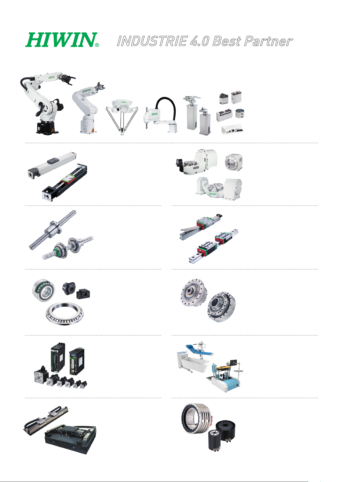
INDUSTRIE 4.0 Best Partner
Multi-Axis Robot
Pick-and-place / Assembly /
Array and packaging / Semiconductor /
Electro-Optical industry /
Automotive industry / Food industry
• Articulated Robot
• Delta Robot
• SCARA Robot
• Wafer Robot
• Electric Gripper
• Integrated Electric Gripper
• Rotary Joint
Single-Axis Robot
Precision / Semiconductor /
Medical / FPD
• KK, SK
• KS, KA
• KU, KE, KC
Ballscrew
Precision Ground / Rolled
• Super S series
• Super T series
• Mini Roller
• Ecological & Economical
lubrication Module E2
• Rotating Nut (R1)
• Energy-Saving & Thermal-
Controlling (Cool Type)
• Heavy Load Series (RD)
• Ball Spline
Bearing
Machine tools / Robot
• Crossed Roller Bearings
• Ballscrew Bearings
• Linear Bearing
• Support Unit
Torque Motor
Rotary Table
Aerospace / Medical / Automotive industry /
Machine tools / Machinery industry
• RAB Series
• RAS Series
• RCV Series
• RCH Series
Linear Guideway
Automation / Semiconductor / Medical
• Ball Type--HG, EG, WE, MG, CG
• Quiet Type--QH, QE, QW, QR
• Other--RG, E2, PG, SE, RC
DATORKER® Robot Reducer
Robots / Automation equipment /
Semiconductor equipment / Machine tools
• WUT Type-Combination Type (P)
• WUI Type-Component Type (C)
• WTI Type-Combination Type (P)
• WTI Type-Sealed type (A)
AC Servo Motor & Drive
Semiconductor / Packaging machine
/SMT / Food industry / LCD
• Drives-D1, D1-N, D2T
• Motors-50W~2000W
Linear Motor
Automated transport / AOI application
/ Precision / Semiconductor
• Iron-core Linear Motor
• Coreless Linear Motor
• Linear Turbo Motor LMT
• Planar Servo Motor
• Air Bearing Platform
• X-Y Stage
• Gantry Systems
Medical Equipment
Hospital / Rehabilitation centers /
Nursing homes
• Robotic Gait Training System
• Hygiene System
• Robotic Endoscope HolderS
Torque Motor &
Direct Drive Motor
Inspection / Testing equipment /
Machine tools / Robot
• Rotary Tables-TMS,TMY,TMN
• TMRW Series
• TMRI Series

C13UE001-1903
Warranty Terms and Conditions
The period of warranty shall commence at the received date of HIWIN product
(hereafter called “product”) and shall cover a period of 12 months. The warranty does
not cover any of the damage and failure resulting from:
The damage caused by using with the production line or the peripheral
equipment not constructed by HIWIN.
Operating method, environment and storage specifications not
specifically recommended in the product manual.
The damage caused by changing installation place, changing working
environment, or improper transfer after being installed by the
professional installer.
Product or peripheral equipment damaged due to collision or accident
caused by improper operation or installation by the unauthorized staff.
Installing non-genuine HIWIN products.
The following conditions are not covered by the warranty:
Product serial number or date of manufacture (month and year) cannot
be verified.
Using non-genuine HIWIN products.
Adding or removing any components into/out the product without
authorized.
Any modification of the wiring and the cable of the product.
Any modification of the appearance of the product; removal of the
components inside the product. e.g., remove the outer cover, product
drilling or cutting.
Damage caused by any natural disaster. i.e., fire, earthquake, tsunami,
lightning, windstorms and floods, tornado, typhoon, hurricane etc.
HIWIN does not provide any warranty or compensation to all the damage caused
by above-mentioned circumstances unless the user can prove that the product is
defective.
For more information towards warranty terms and conditions, please contact the
technician or the dealer who you purchased with.
1
in serious hazard or personal injury. Please be sure to
in personal injury or product damage. Please be sure to
effector or the cable for devices should be installed
professional staff to avoid damaging the
Improper modification or disassemble the robot might reduce
the robot function, stability or life.
The end-
and designed by a
C13UE001-1903
robot and robot malfunction.
Please contact the technician for special modification coming
from production line set up.
For the safety reason, any modification for HIWIN product is
strictly prohibited.
Safety Precautions
1. Safety Information
Safety Responsibility and Effect
This chapter explains how to use the robot safely. Be sure to read this
chapter carefully before using the robot.
The user of the HIWIN industrial robot has responsibility to design and
install the safety device meeting the industrial safety regulations in order
to ensure personal safety.
2. Description Related to Safety
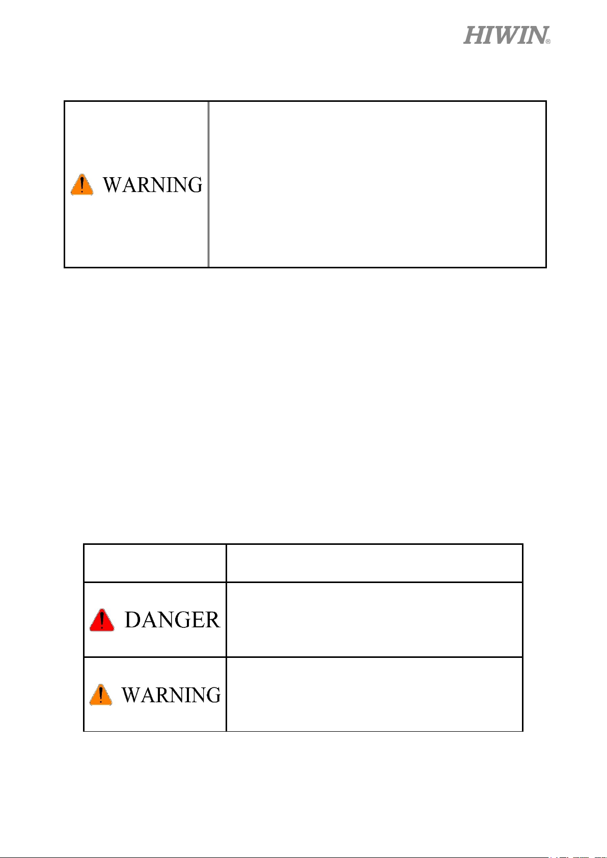
I. Safety Symbols
Carefully read the instructions in the user manual prior to robot use. The
following shows the safety symbols used in this user manual.
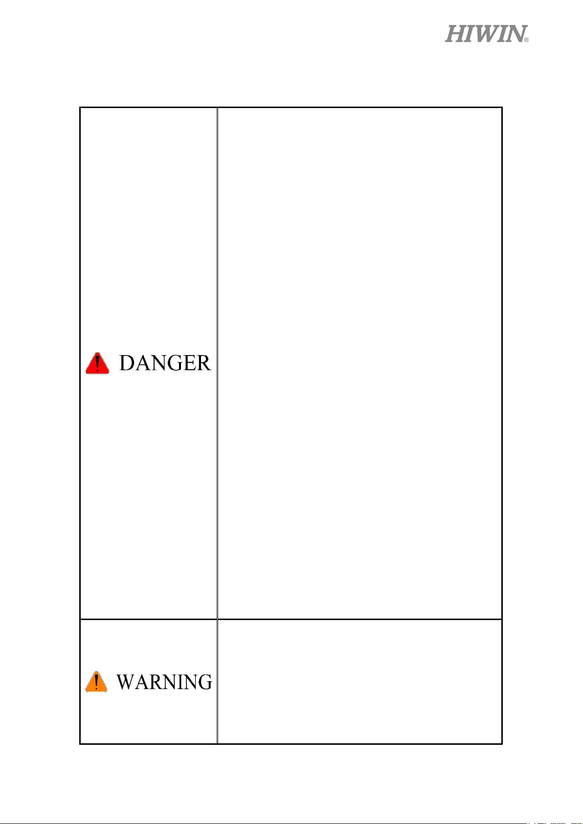
Symbol Description
Failure to follow instructions with this symbol may result
comply with these instructions.
Failure to follow instructions with this symbol may result
comply with these instructions.
2

in poor product performance. Please be sure to comply
Failure to follow instructions with this symbol may result
with these instructions.
II. Working Person
The personnel can be classified as follows
Operator:
Turns robot controller ON/OFF
Starts robot program from operator’s panel
Restore system alarm status
Programmer or teaching operator:
Operates the robot
Teaches robot inside the safety fence
Maintenance engineer:
C13UE001-1903
Operates the robot
Teaches robot inside the safety fence
Does maintenance, adjustment, replacement
Programmer and the maintenance engineer must be trained for proper robot
operation
3
All operating procedures should be assessed by
emergency or
abnormal situation, please press the emergency stop
When considering safety of the robot, the robot and
ystem must be considered at the same time. Be
with an appropriate safety device to stop the
While installing or removing mechanical
Ensure the weight of workpiece does not exceed the
defined by the system integrator in accordance
with ISO 10218-1/-2.
To ensure personal safety, robot installation must
The control cabinet should not be placed near high
voltage or machines that generate electromagnetic
3. Warning
3.1 Common Safety Issues
professional and in compliance with related industrial
safety regulations.
When operating robot, operator needs to wear safety
equipment, such as smock for working environment,
safety shoes and helmets.
When encountering danger or other
button immediately and move the arm away with low
speed in manual mode.
the s
sure to install safety fence or other safety equipment
C13UE001-1903
and the operator must stand outside the safety fence
while operating the robot.
A safety zone should be established around the robot
unauthorized personnel from access.
components, be aware of a falling piece which may
cause injury to operator.
rated load or the tolerable torque. Exceeding these
values could lead to the driver alarm or malfunction
of the robot.
Do not climb on robot.
The installation for emergency functions shall be
The personnel operating robot should be trained and
licensed.
comply with this manual and related industrial safety
regulations.
4
fields to prevent interference that could cause the
pair components may cause
Beware of the heat generated by the controller and
Do not overbend the cable to avoid poor circuit
be done outside of the safety
Please contact us if the replacement of the
Be sure to carry out regular maintenance,
Prior to repair and maintenance, please turn off
When replacing the components, avoid foreign
robot to deviation or malfunction.
Using non-HIWIN re
robot damage or malfunction.
servo motor.
contact.
3.2 Operation
Programming must
C13UE001-1903
3.3 Maintenance
fence. If it is inevitable to enter the safety fence,
the emergency stop button must be pressed.
Please contact us if the procedure not specified by
HIWIN is needed.
component not specified by HIWIN is needed.
otherwise it will affect the service life of the robot
or other unexpected danger.
power supply.
Maintenance and repair should be performed by a
qualified operator with a complete understanding
of the entire system to avoid risk of robot damage
and personal injury.
material going into the robot.
5
More attention must be paid to the design of the
effector to prevent power loss or any other
errors that could lead to workpiece falling or
type end effector is usually equipped
with high voltage, high temperature and active
The end effector may be equipped with its own
control unit. Be sure the control unit does not
the pneumatic or hydraulic system,
the relief valve, so that can be applied in an
emergency.
at least one device for immediate halt of n
servo motor will be cut, and all movements will
be stopped. And the control system will be shut
down. Emergency stop should be reset if the
Avoid using emergency stop to replace a normal
stop procedure. This could lead to unnecessary
3.4 End Effector
end
damage.
The tool-
rotary shaft. Special attention should be paid to the
operating safety.
The end effector should be mounted firmly on the
robot to avoid workpiece release during operation
which may cause personal injury or hazard.
interfere with robot operation.
C13UE001-1903
3.5 Pneumatic, Hydraulic System
When using
the gripped workpiece may fall due to insufficient
pressure or gravity.
The pneumatic system must be equipped with
3.6 Emergency Stop
The robot or other control component should have
function, such as an emergency stop switch.
The emergency stop button must be installed in an
easily accessible location for quick stop.
While executing an emergency stop, power to the
restoration of operating procedure is wanted.
6

loss to robot.
4. Intended use
HIWIN robots are industrial robots and intended for pick-and-place,
C13UE001-1903
handling, assembling, deburring, grinding and polishing. Use is only permitted
under the specified environment, for more detailed information please see
section 1.5 environmental conditions.
Use is not permitted under the following conditions:
Use in potentially explosive environments
Use without performing risk assessments
Transportation of people and animals
Operation outside the allowed operating parameters
5. Disposal
The disposal of HIWIN robot shall be in accordance with the local
environmental regulations.
7

C13UE001-1902
Content
1. TRANSPORTATION AND INSTALLATION .......................................................................... 10
1.1 TRANSPORTATION ....................................................................................................................... 10
1.2 INSTALLATION ............................................................................................................................. 19
1.3 CONNECTION WITH THE CONTROLLER ......................................................................................... 21
1.4 GROUNDING ................................................................................................................................. 23
1.5 OPERATING AMBIENT CONDITIONS .............................................................................................. 23
1.6 STANDARD AND OPTIONAL EQUIPMENT LIST ............................................................................... 24
2. BASIC SPECIFICATIONS ........................................................................................................ 25
4.1 DESCRIPTION OF MODEL NAME ................................................................................................... 25
4.2 LABELS ........................................................................................................................................ 26
4.3 ROBOT SPECIFICATIONS ............................................................................................................... 28
4.4 OUTER DIMENSIONS AND MOTION RANGE .................................................................................. 30
4.5 WRIST LOAD CONDITIONS ........................................................................................................... 34
3. EQUIPMENT MOUNTING SURFACE AND INTERFACE ..................................................... 38
3.1 MOUNTING SURFACE FOR END EFFECTOR ................................................................................... 38
3.2 MOUNTING SURFACE ON THE ROBOT ........................................................................................... 38
3.3 INTERFACE OF AIR SUPPLY .......................................................................................................... 41
3.4 R-I/O INTERFACE ......................................................................................................................... 43
4. CALIBRATION ......................................................................................................................... 47
4.1 ZERO-POSITION SETTING ............................................................................................................. 47
5. MANUAL BRAKE RELEASE DEVICE (OPTIONAL) ............................................................ 51
5.1 SAFETY PRECAUTIONS ................................................................................................................. 51
5.2 CONFIRMATION BEFORE USING .................................................................................................... 52
5.3 OPERATION .................................................................................................................................. 54
6. MAINTENANCE AND INSPECTION ...................................................................................... 56
6.1 PERIODIC INSPECTION ITEMS ....................................................................................................... 56
6.2 MAINTENANCE ............................................................................................................................ 60
6.2.1 Backup Batteries Replacement .................................................................................................... 60
6.2.2 Timing Belt Replacement ............................................................................................................ 61
6.2.3 Grease Replenishment ................................................................................................................. 65
8

C13UE001-1903
Edition Date Robot type Remark
1.0.0 2018.05.25
1.0.1 2019.01.03
1.0.2 2019.02.19
RA610-GB
RT610-GB
RA610-GB
RT610-GB
RA610-GB
RT610-GB
First edition released
Added new chapter 5 manual brake
release device
Modified chapter 2.2 labels
9

C13UE001-1903
1. Transportation and Installation
1.1 Transportation
Sling, crane or forklift truck can be used to transport the robot. The transportation
procedure is as follows:
Transport by forklift truck:
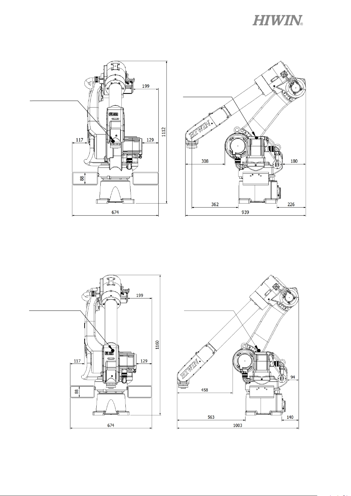
Step1. Move the robot into its transport position and the angle of each joint is shown in
the table of Figure 1-1. Transport dimensions are shown in Figure 1-2(a)~(d).
Step2. Secure the suspension plate to the robot with four M8x1.25Px20L head screw as
shown in Figure 1-3(a)~(d).
Step3. Move the robot to the desired position by forklift truck.
Step4. Remove the suspension plate and firmly secure the robot.
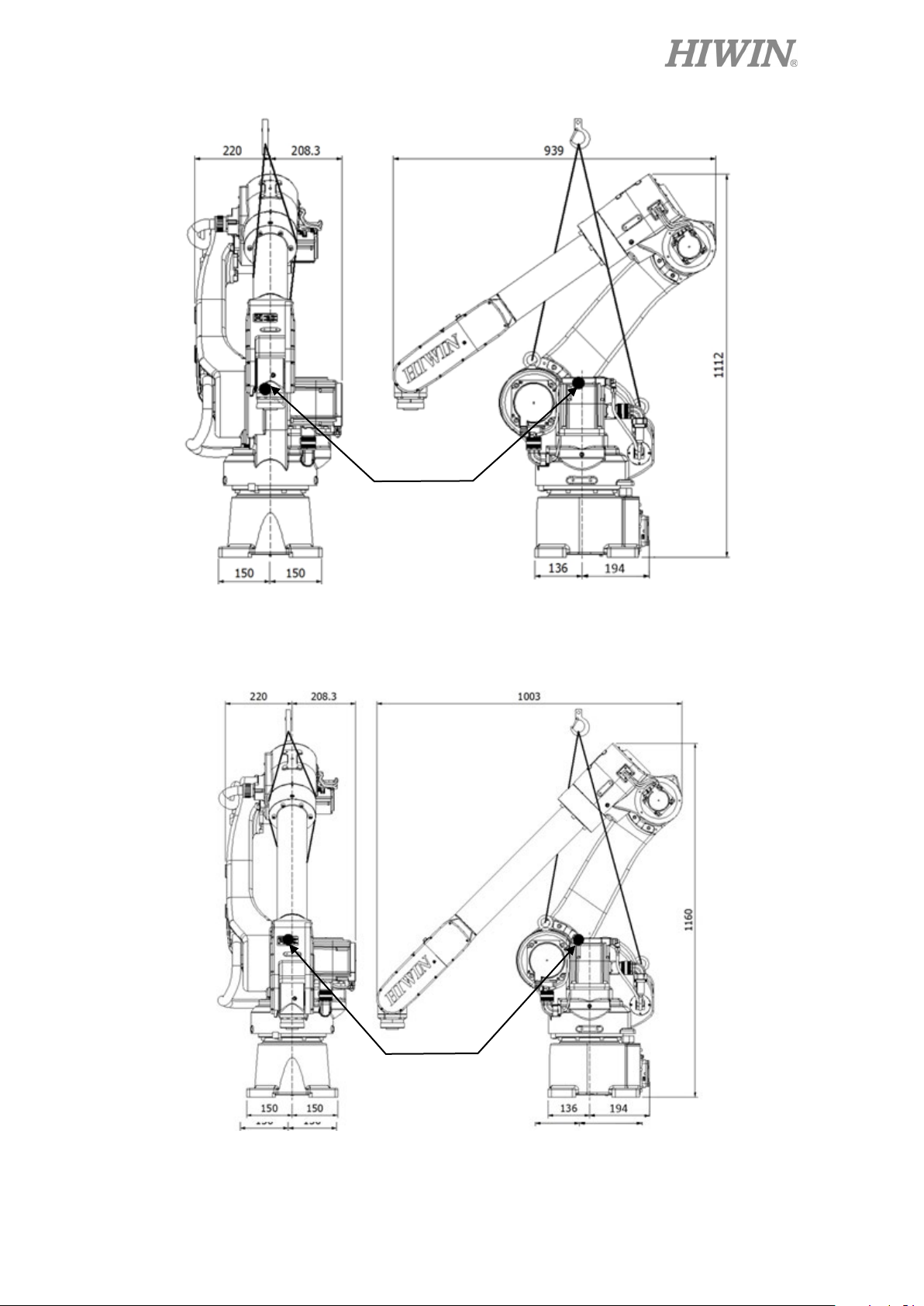
Transport by sling and crane:
Step1. Move the robot into its transport position and the angle of each joint is shown in
the table of Figure 1-1. Transport dimensions are shown in Figure 1-2(a)~(d).
Step2. Secure two M12x1.75Px22L eye bolts to the robot as shown in Figure 1-4
(a)~(e).
Step3. Move the robot to the desired position by sling and crane.
Step4. Remove the eye bolts and firmly secure the robot.
(The transportation of RA610-GB and RT610-GB are the same. The following
figures only show the transportation of RA610-GB.)
Please refer to section 1.2~1.5 for robot installation and precautions.
10
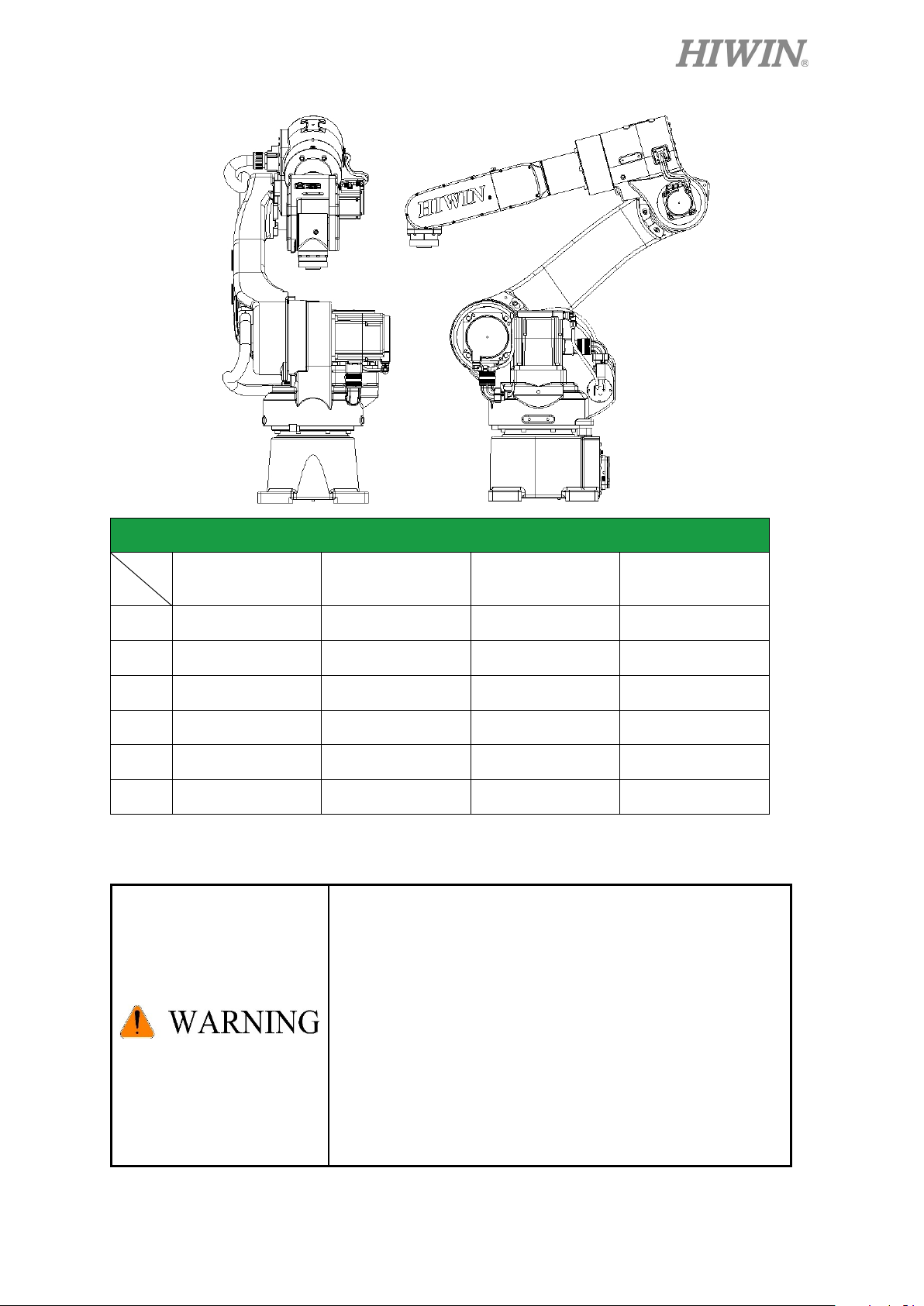
Transport position
RA610-1355-GB
RA610-1476-GB
RA610-1672-GB
RA610-1869-GB
0˚
0˚
0˚
0˚
45˚
55˚
45˚
35˚
J3
-75˚
-75˚
-80˚
-80˚
0˚
0˚
0˚
0˚
-60˚
-70˚
-55˚
-45˚
0˚
0˚
0˚
0˚
Before carrying the robot, be sure to remove the end
Please keep stable, slow down and avoid excessive
C13UE001-1903
RT610-1355-GB
RT610-1476-GB
J1
J2
J4
J5
J6
Figure 1-1 Transport position
effector which changes the center of gravity.
vibration or shock during transportation.
While placing the robot be sure to avoid the robot and
the installation surface collision.
RT610-1672-GB
RT610-1869-GB
After removing the suspension plate, please maintain it
properly for re-transportation.
Before operation, remove the suspension plate to avoid
danger.
11
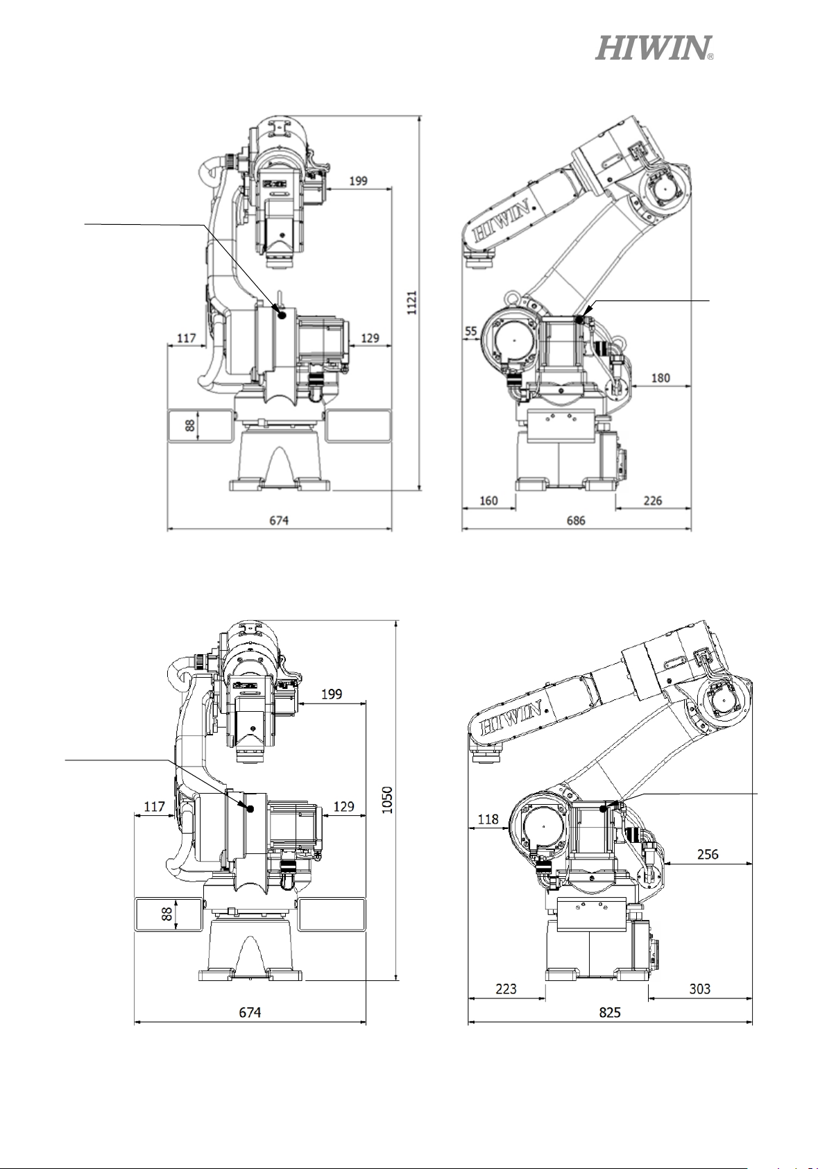
Center of gravity
C13UE001-1903
Center of gravity
Center of gravity
Figure 1-2(a) RA610-1355-GB Transport dimensions
RT610 -1355-GB Transport dimensions
Center of gravity
Figure 1-2(b) RA610-1476-GB Transport dimensions
RT610-1476-GB Transport dimensions
12
C13UE001-1903
Center of gravity
Center of gravity
Figure 1-2(c) RA610-1672-GB Transport dimensions
RT610-1672-GB Transport dimensions
Center of gravity
Center of gravity
Figure 1-2(d) RA610-1869-GB Transport dimensions
RT610-1869-GB Transport dimensions
13
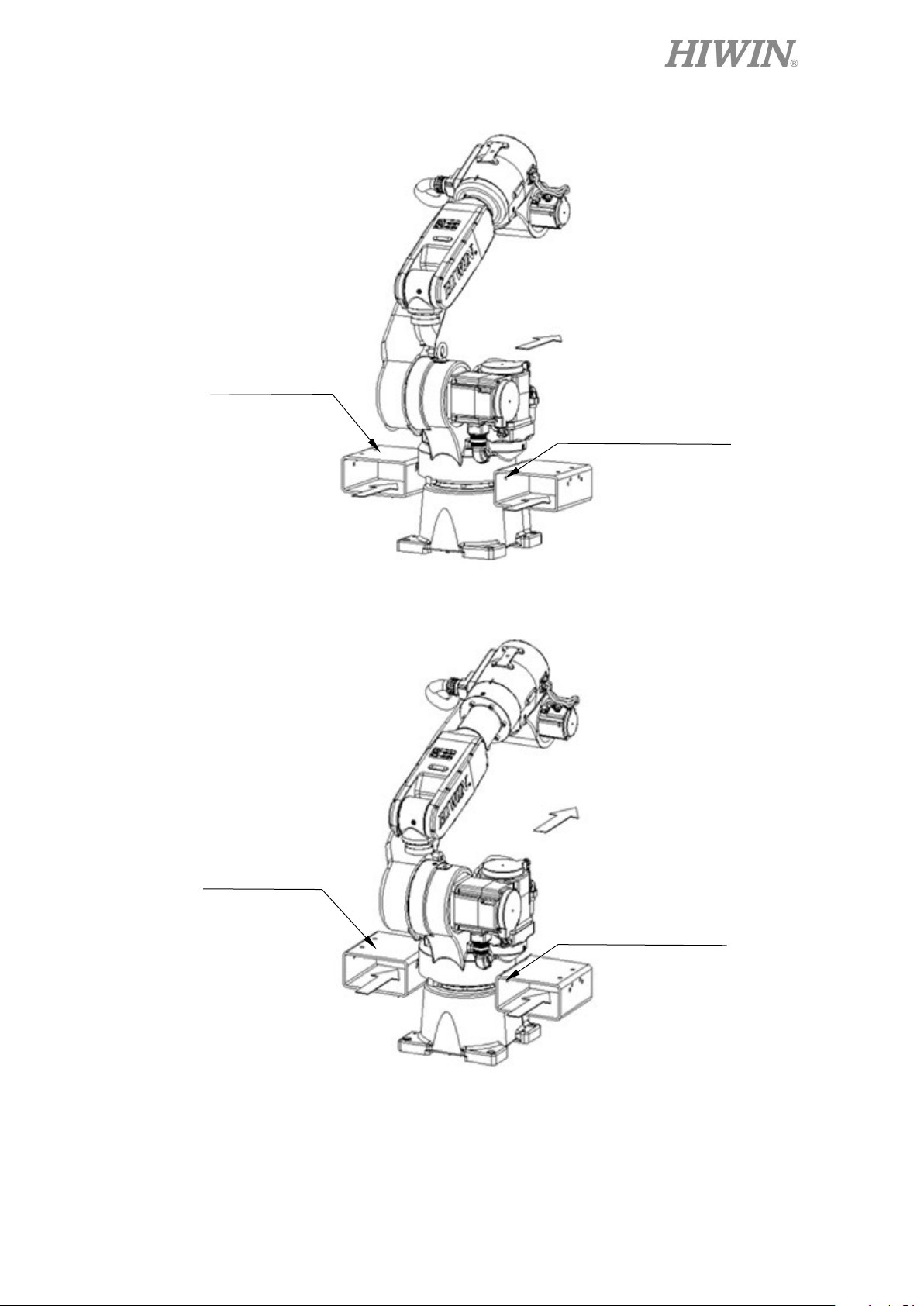
Direction for forklift
C13UE001-1903
Suspension plate
Screw: 4-M8x1.25Px20L
Washer: 4-M8
Figure 1-3(a) RA610-1355-GB Transport by forklift truck
RT610-1355-GB Transport by forklift truck
Suspension plate
Direction for forklift
Screw: 4-M8x1.25Px20L
Washer: 4-M8
Figure 1-3(b) RA610-1476-GB Transport by forklift truck
RT610-1476-GB Transport by forklift truck
14
C13UE001-1903
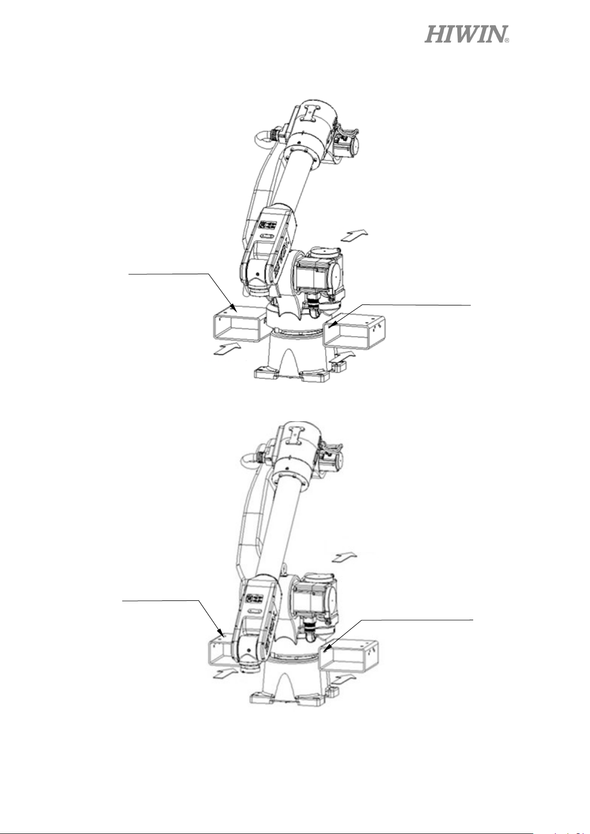
Suspension plate
Direction for forklift
Screw: 4-M8x1.25Px20L
Washer: 4-M8
Figure 1-3(c) RA610-1672-GB Transport by forklift truck
RT610-1672-GB Transport by forklift truck
Suspension plate
Direction for forklift
Screw: 4-M8x1.25Px20L
Washer: 4-M8
Figure 1-3(d) RA610-1869-GB Transport by forklift truck
RT610-1869-GB Transport by forklift truck
15
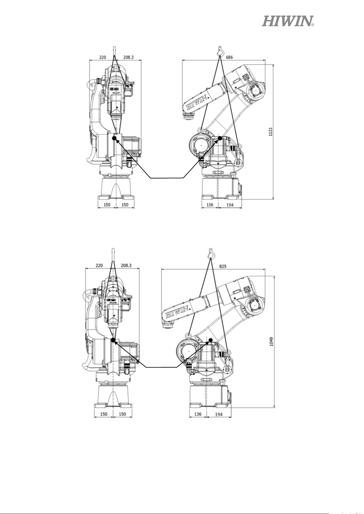
gravity
gravity
Center of
C13UE001-1903
Figure 1-4(a) RA610-1355-GB Transport by sling
RT610-1355-GB Transport by sling
Center of
Figure 1-4(b) RA610-1476-GB Transport by sling
RT610-1476-GB Transport by sling
16
Center of gravity
C13UE001-1903
Figure 1-4(c) RA610-1672-GB Transport by sling
RT610-1672-GB Transport by sling
Center of gravity
Figure 1-4(d) RA610-1869-GB Transport by sling
RT610-1869-GB Transport by sling
17
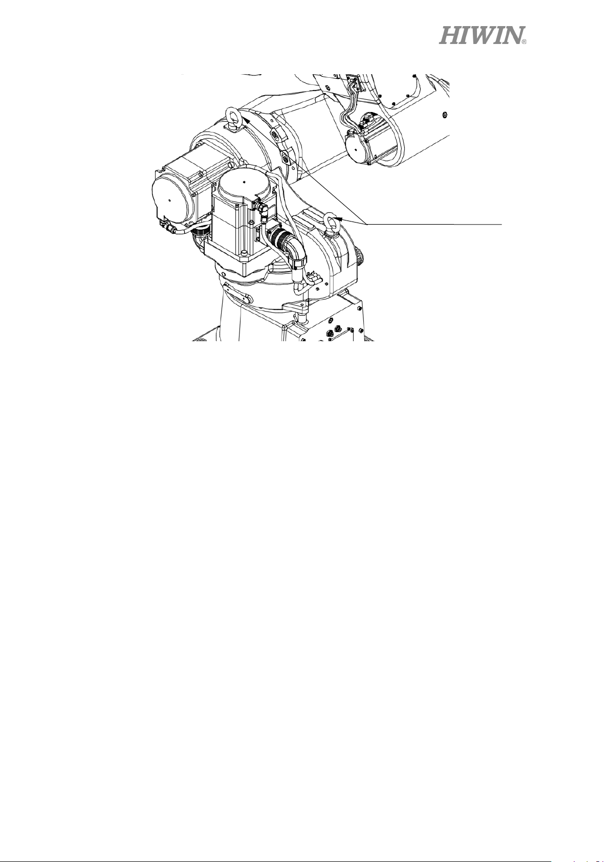
Sling installation position
C13UE001-1903
2-M12 Eyebolt
Figure 1-4(e) Eye bolt securement
18
C13UE001-1903
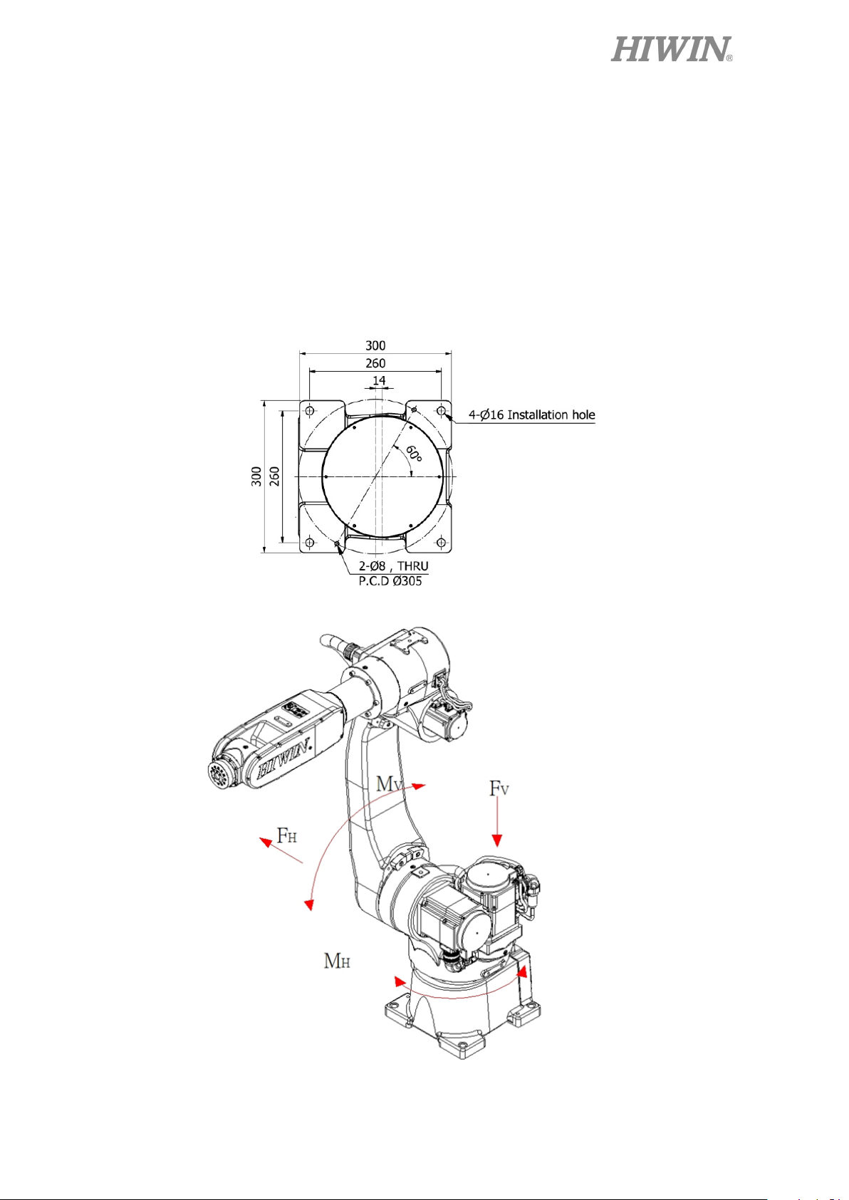
1.2 Installation
Figure 1-5 shows the installation dimensions of the robot. According to the
dimensions, fix the robot with M14 installation bolt on the installation surface. Figure 1-6
and Table 1-1 show the forces and moments acting on the installation surface. The
installation surface must have sufficient strength to withstand the dynamic movement of
the robot when operating at maximum speed.
(The installation interface of RA610-GB and RT610-GB are the same. The following
figure only shows the base dimensions of RA610-GB.)
Figure 1-5 Base dimension
Figure 1-6 Forces and moments acting on the installation surface
19
 Loading...