


INDUSTRIE 4.0 Best Partner
Multi Axis Robot
Pick-and-place / Assembly /
Array and packaging / Semiconductor /
Electro-Optical industry /
Automotive industry / Food industry
ßArticulated Robot
ßDelta Robot
ßSCARA Robot
ßWafer Robot
ßElectric Gripper
ßIntegrated Electric Gripper
ßRotary Joint
Single Axis Robot
Precision / Semiconductor /
Medical / FPD
ßKK, SK
ßKS, KA
ßKU, KE, KC
Ballscrew
Precision Ground / Rolled
ßSuper S series
ßSuper T series
ßMini Roller
ßEcological & Economical
lubrication Module E2
ßRotating Nut (R1)
ßEnergy-Saving & Thermal-
Controlling (C1)
ßHeavy Load Series (RD)
ßBall Spline
Medical Equipment
Hospital / Rehabilitation centers /
Nursing homes
ßRobotic Gait Training System
ßHygiene System
ßRobotic Endoscope Holder
Direct Drive
Rotary Table
Aerospace / Medical / Automotive industry /
Machine tools / Machinery industry
ßRAB Series
ßRAS Series
ßRCV Series
ßRCH Series
Linear Guideway
Automation / Semiconductor / Medical
ßBall Type--HG, EG, WE, MG, CG
ßQuiet Type--QH, QE, QW, QR
ßOther--RG, E2, PG, SE, RC
Bearing
Machine tools / Robot
ßCrossed Roller Bearings
ßBall Screw Bearings
ßLinear Bearing
ßSupport Unit
AC Servo Motor & Drive
Semiconductor / Packaging machine
/SMT / Food industry / LCD
ßDrives-D1, D1-N, D2T
ßMotors-50W~2000W
Linear Motor
Automated transport / AOI application
/ Precision / Semiconductor
ßIron-core Linear Motor
ßCoreless Linear Motor
ßLinear Turbo Motor LMT
ßPlanar Servo Motor
ßAir Bearing Platform
ßX-Y Stage
ßGantry Systems
Driven Tool Holders
All kinds of turret
ßVDI Systems
Radial Series, Axial Series, MT
ßBMT Systems
DS, NM, GW, FO, MT, OM, MS
Torque Motor
(Direct Drive Motor)
Inspection / Testing equipment /
Machine tools / Robot
ßRotary Tables-TMS,TMY,TMN
ßTMRW Series
ßTMRI Series
C18UE001-1804
Warranty Terms and Conditions
The period of warranty shall commence at the received date of HIWIN product
(hereafter called “product”) and shall cover a period of 12 months. The warranty does
not cover any of the damage and failure resulting from:
The damage caused by using with the production line or the peripheral
equipment not constructed by HIWIN.
Operating method, environment and storage specifications not specifically
recommended in the product manual.
The damage caused by changing installation place, changing working
environment, or improper transfer after being installed by the professional
installer.
Product or peripheral equipment damaged due to collision or accident caused by
improper operation or installation by the unauthorized staff.
Installing non-genuine HIWIN products.
The following conditions are not covered by the warranty:
Product serial number or date of manufacture (month and year) cannot be
verified.
Using non-genuine HIWIN products.
Adding or removing any components into/out the product without authorized.
Any modification of the wiring and the cable of the product.
Any modification of the appearance of the product; removal of the components
inside the product. e.g., remove the outer cover, product drilling or cutting.
Damage caused by any natural disaster. i.e., fire, earthquake, tsunami, lightning,
windstorms and floods, tornado, typhoon, hurricane etc.
HIWIN does not provide any warranty or compensation to all the damage caused by
above-mentioned circumstances unless the user can prove that the product is defective.
For more information towards warranty terms and conditions, please contact the
technician or the dealer who you purchased with.
Improper modification or disassemble the robot might reduce
the robot function, stability or life.
The end-effector or the cable for devices should be installed
1.
Safety Information
Safety Responsibility and Effect
This chapter explains how to use the robot safely. Be sure to read this
C18UE001-1804
and designed by a professional staff to avoid damaging the
robot and robot malfunction.
Please contact the technician for special modification coming
from production line set up.
For the safety reason, any modification for HIWIN product is
strictly prohibited.
Safety Precautions
chapter carefully before using the robot.
The user of the HIWIN industrial robot has responsibility to design and
install the safety device meeting the industrial safety regulations in order to
ensure personal safety.
2.
Description Related to Safety
I. Safety Symbols
Carefully read the instructions in the user manual prior to robot use. The
following shows the safety symbols used in this user manual.
Symbol Description
Failure to follow instructions with this symbol may result
in serious hazard or personal injury. Please be sure to
comply with these instructions.
Failure to follow instructions with this symbol may result
in personal injury or product damage. Please be sure to
comply with these instructions.
Failure to follow instructions with this symbol may result
in poor product performance. Please be sure to comply
with these instructions.
II. Working Person
The personnel can be classified as follows
Operator:
3.
C18UE001-1804
Turns robot controller ON/OFF
Starts robot program from operator’s panel
Reset system alarm
Programmer or teaching operator:
Operates the robot
Teaches robot inside the safety fence
Maintenance engineer:
Operates the robot
Teaches robot inside the safety fence
Does maintenance, adjustment, replacement
Programmer and the maintenance engineer must be trained for proper robot
operation.
Warning
3.1 Common Safety Issues
All operating procedures should be assessed by
professional and in compliance with related
industrial safety regulations.
When operating robot, operator needs to wear
safety equipment, such as smock for working
environment, safety shoes and helmets.
When encountering danger or other emergency or
abnormal situation, please press the emergency stop
button immediately and move the arm away with
low speed in manual mode.
When considering safety of the robot, the robot and
the system must be considered at the same time. Be
sure to install safety fence or other safety equipment
and the operator must stand outside the safety fence
while operating the robot.
A safety zone should be established around the
robot with an appropriate safety device to stop the
unauthorized personnel from access.
While installing or removing mechanical
components, be aware of a falling piece which may
cause injury to operator.
C18UE001-1804
Ensure the weight of workpiece does not exceed the
rated load or the tolerable torque. Exceeding these
values could lead to the driver alarm or malfunction
of the robot.
Do not climb on robot.
The personnel installing robot should be trained and
licensed.
To ensure personal safety, robot installation must
comply with this manual and related industrial
safety regulations.
The control cabinet should not be placed near high
voltage or machines that generate electromagnetic
fields to prevent interference that could cause the
robot to deviation or malfunction.
Using non-HIWIN repair components may cause
3.2 Operation
3.3 Maintenance
robot damage or malfunction.
Beware of the heat generated by the controller and
servo motor.
Do not overbend the cable to avoid poor circuit
contact.
Programming should be done outside of the safety
fence. If it is inevitable to enter the safety fence, be
prepared to press the emergency stop button
whenever necessary. Operation should be restricted
at low speed and beware of surrounding safety.
Please contact us if the procedure not specified by
HIWIN is needed.
Please contact us if the replacement of the
component not specified by HIWIN is needed.
Be sure to carry out regular maintenance, otherwise
it will affect the service life of the robot or other
unexpected danger.
3.4 End Effector
C18UE001-1804
Prior to repair and maintenance, please turn off
power supply.
Maintenance and repair should be performed by a
qualified operator with a complete understanding of
the entire system to avoid risk of robot damage and
personal injury.
When replacing the components, avoid foreign
material going into the robot.
More attention must be paid to the design of the end
effector to prevent power loss or any other errors
that could lead to workpiece falling or damage.
The tool-type end effector is usually equipped with
high voltage, high temperature and active rotary
3.5 Pneumatic, Hydraulic System
3.6 Emergency Stop
shaft. Special attention should be paid to the
operating safety.
The end effector should be mounted firmly on the
robot to avoid workpiece release during operation
which may cause personal injury or hazard.
The end effector may be equipped with its own
control unit. Be sure the control unit does not
interfere with robot operation.
When using the pneumatic or hydraulic system, the
gripped workpiece may fall due to insufficient
pressure or gravity.
The robot or other control component should have
at least one device for immediate halt of n function,
such as an emergency stop switch.
The emergency stop button must be installed in an
easily accessible location for quick stop.
While executing an emergency stop, power to the

C18UE001-1804
servo motor will be cut, and all movements will be
stopped. And the control system will be shut down.
Emergency stop should be reset if the restoration of
operating procedure is wanted.
Avoid using emergency stop to replace a normal
stop procedure. This could lead to unnecessary loss
to robot.
C18UE001-1804
1.Transportation and Installation
1.1 Transportation
1.2 Installation
1.3 Connection with the Controller
1.4 Grounding
1.5 Operating Ambient Conditions
1.6 Standard and Optional Equipment List
2.Basic Specifications
2.1 Description of Serial Number
2.2 Labels
2.3 Robot Specifications
Content
2.4 Outer Dimensions and Motion Range
2.5 Wrist Moment Conditions
3.Equipment Mounting Surface and Interface
3.1 Mounting Surface for End Effector
3.2 Pneumatic Interface
3.3 I/O Interface
4.Zero-Position
4.1 Zero Position Setting
5.Maintenance and Inspection
5.1 Periodic Inspection Items
5.2 Repair
5.2.1 Backup Batteries Replacement
5.2.2 Timing Belt Replacement
5.2.3 Grease Replenishment

C18UE001-1804
Version Date Product Note
1.0.0 2017.12.18
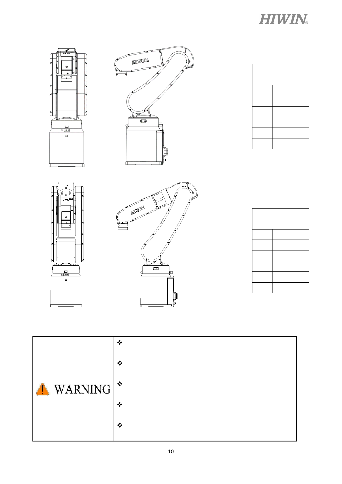
RT605-710-GB
RT605-710-GB
First edition
Manual specification updated
2.0.0 2018.01.08
RT605-909-GB
RT605-909-GB

C18UE001-1804
1. Transportation and Installation
1.1 Transportation
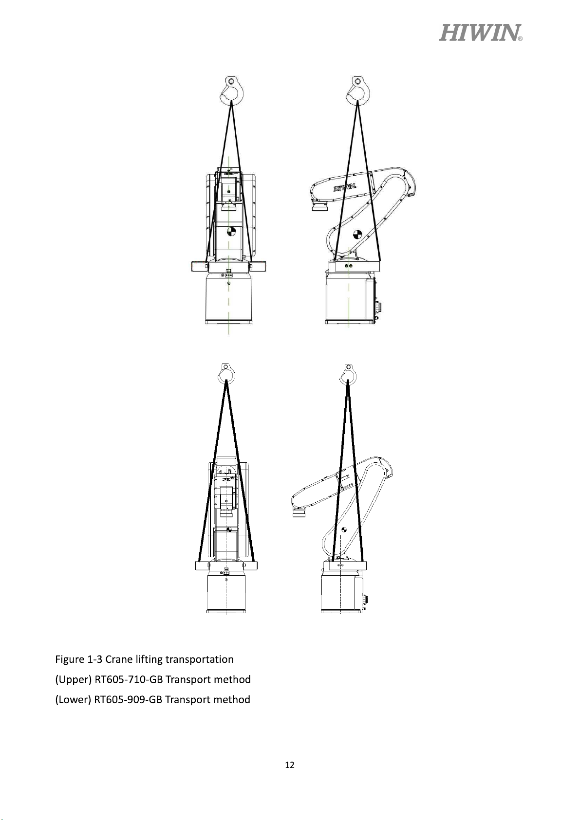
Sling can be used to transport the robot. The transportation procedure is as follows:
Step1. Move the robot into its transport posture and the angle of each joint is shown in the table
of Figure 1-1.
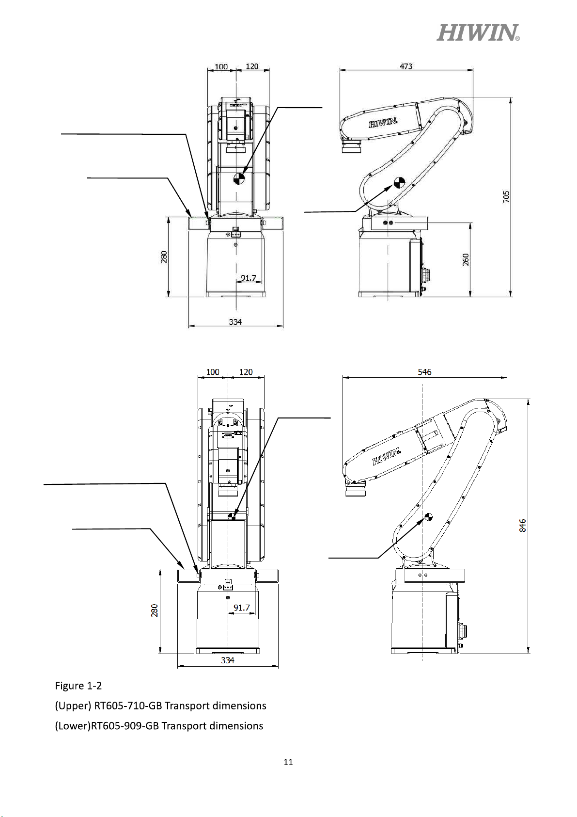
Step2. Secure the suspension plate to the robot with four M8×1.25P×12L screws as shown in
Figure 1-2. Make the sling go through the suspension plate to keep the center of gravity
under the hanging point shown as Figure 1-3. Please ensure the robot is in stable
condition to avoid overturning.
Step3. Move the robot to the desired position by using sling.
Step4. Remove the suspension plate.
C18UE001-1804
RT605-710-GB
Transport posture
J1 0°
J2 45°
J3 -55°
J4 0°
J5 -80°
J6 0°
RT605-909-GB
Transport posture
J1 0°
J2 30°
J3 -55°
J4 0°
J5 -65°
J6 0°
Figure 1-1 Transport posture
Before carrying the robot, be sure to remove the end
effector which changes the center of gravity.
Please keep stable, slow down and avoid excessive
vibration or shock during transportation.
While placing the robot be sure to avoid the robot and the
installation surface collision.
After removing the suspension plate, please maintain it
properly for re-transportation.
Before operation, remove the suspension plate to avoid
danger.
C18UE001-1804
Hexagon socket cap screw
M8x1.25Px12L
Suspension plate
Center of
gravity
Center of
gravity
Hexagon socket cap screw
M8x1.25Px12L
Suspension plate
Center of
gravity
Center of
gravity
C18UE001-1804
C18UE001-1804
1.2 Installation
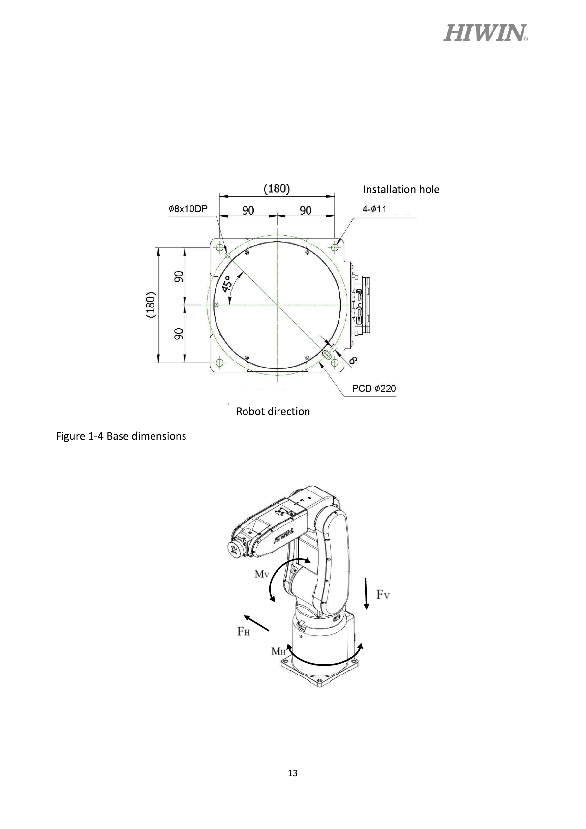
Figure 1-4 shows the installation dimensions of the robot. According to the dimensions, fix
the robot on the installation surface with M10 screws. Figure 1-5, table 1-1 and table 1-2 show
the forces and moments acting on the installation surface during operation. The strength of
surface must be considered when installing the robot.
Figure 1-5 Forces and moments acting on the installation surface
C18UE001-1804
Table 1-1 RT605-710-GB Value of forces and moments acting on the installation surface
Vertical moment
Vertical force
Horizontal moment
Horizontal force
Mv (Nm)
Fv (N)
MH (Nm)
Stop 144 441 0 0
Acceleration
382 1009 149 456
/Deceleration
Power cut stop
462 1199 248 760
Table 1-2 RT605-909-GB Value of forces and moments acting on the installation surface
Vertical moment
Vertical force
Horizontal moment
Horizontal force
Mv (Nm)
Fv (N)
MH (Nm)
Stop 160 490 0 0
FH (N)
FH (N)
Acceleration
/Deceleration
Power cut stop
526 1205 244 748
660 1467 407 1246
Ensure the installation surface is smooth plane which is
recommended to be 6.3a or less for the roughness. If the
installation surface is rough, the robot could produce the
position shift during the operation.
Ensure the position of the installation surface for the robot will
not shift owing to the movement.
Ensure the strength of the installation surface for the robot will
not be damaged owing to the movement.

C18UE001-1804
+
+
-
+
+
+
+
-
1.3 Connection with the Controller
Figure 1-6 shows the structure drawing of the robot. Figure 1-7 shows the connection
between robot, controller, teach pendant and power source. Figure 1-8and Figure 1-9 show the
interface of J1 and the pin assignment of CN2 connector.
Joint 4
Joint 5
Joint 6
J6
J5
Joint 3
Joint 2
J4
-
J2
-
J1
-
J3
Joint 1
Figure 1-6 Drawing of robot structure
Teach pendant
Power source
CN2
Controller
Figure 1-7 Robot and controller connection

C18UE001-1804
Battery box
Air out socket
Power/signal socket
Air in socket
Figure 1-8 Interface at the rear of J1
Figure 1-9 Pin assignment of CN2 connector
When connecting the cable, be sure to turn off power supply
first.

C18UE001-1804
1.4 Grounding
Figure 1-10 shows the grounding connection of the robot with the screw (M5×0.8P×8L).
Grounding wire
Washer
Figure 1-10 Grounding method
1.5 Operating Ambient Conditions
The robot operating ambient conditions is shown in Table 1-3.
Table 1-3 Ambient conditions
Ambient temperature 0~45 [Note 1]
Ambient relative humidity 75% R.H. or less
Altitude Up to 1000 m above mean sea level
Vibration 0.5G or less
Ambient conditions
Screw
No condensation permissible
Environment
Do not use under corrosive environment
Do not use under flammable environment
Do not use under explosive environment
Do not use under radiative environment
[Note 1]: When the robot is stopped for a long period of time at the temperature near 0 , the robot
operation may have greater resistance in the beginning and then an overload alarm may be raised. It
is recommended to warm up the robot at low speed for a few minutes.

1.6 Standard and Optional Equipment List
Standard and optional equipment list is shown in Table 1-4.
Table 1-4 Standard and optional equipment list
C18UE001-1804
Item
HIWIN
Part No.
Teach pendant AH301401
Calibration tool set 4C201EK1
End effector I/O connector 4CA30008
Connector set 4C201701
Suspension plate set 4C201E41
Robot base (GB) 4C300F42
J2 belt 45310141
J2 belt 453100X8
J3 belt 453100QN
RT605-710-GB
RT605-909-GB
Standard
Optional
Optional
Refer to section
Refer to section
Refer to section
Refer to section
Refer to section
Refer to section
Remark
4.1
3.3
1.1
5.2.2
5.2.2
5.2.2
J3 belt 453100X9
J5 J6 belt
453100MY
J1~J4 grease (16KG) 47110035
J5~J6 grease (16KG) 47110037
Encoder battery 462600LN
CN3 Emergency stop set
4C7013F2
5M
External input/output
4C201DY1
wiring set
External input/output
4C201DZ2
expansion module
Cotton filter 4657003Y
Battery 462C0097
Refer to section
Refer to section
Refer to section
Refer to section
Refer to section
5.2.2
5.2.2
5.2.3
5.2.3
5.2.1

2. Basic Specifications
2.1 Description of Serial Number
There is a serial number on the specification label of each robot. The explanation of serial
number and model name are shown in Figure 2-1.
C18UE001-1804
Figure 2-1 Description of serial number
2.2 Labels
The labels on the robot are shown in Table 2-1.
Table 2-1 Labels description
Labels Name Description
Collision
Grounding
Keep safety distance from robot
system, and prevent colliding to
operator during operation.
Make sure grounding is
completed, or it will cause electric
shock.
Electric shock
Pay more attention that the robot
may have a risk of electric shock.

C18UE001-1804
Be aware of transport posture
Transport
posture
when transporting robot, please
refer to section 1.1 for detailed
information.
Robot specification and serial
Specification
number.
The connection port of air tube for
Air in
air input.
The connection port of air tube for
Air out
air output.
Grease in The hole for grease in.
Grease out The hole for grease out.

2.3 Robot Specifications
The robot specifications are shown in Table 2-2.
Table 2-2 Robot specification
Item Specification
Model name RT605-710-GB RT605-909-GB
Degrees of freedom 6
C18UE001-1804
Installation
Floor slope (wall mounting, ceiling mounting) [Note 1]
Load capacity 5kg [Note 2] 5kg [Note 2]
Maximum reach radius 710 mm 909 mm
Cycle time 0.5 s [Note 3]
Repeatability ±0.03 mm ±0.04 mm
J1 ±165°
J2 +85°~ -125°
J3 +185°~ -55°
±165°
+85°~ -125°
+185°~ -55°
Motion range
J4 ±190°
J5 ±115°
J6 ±360°
J1 360°/ s
J2 288°/ s
J3 420°/ s
±190°
±115°
±360°
250°/ s
200°/ s
300°/ s
Maximum speed
J4 444°/ s
J5 450°/ s
444°/ s
450°/ s
J6 720°/ s
Allowable load
moment at
wrist
J4 8.40 N-m
J5 8.40 N-m
J6 5.56 N-m
J4
0.36 kg-
Allowable load
J5
0.36 kg-
inertia at wrist
J6
0.13 kg-
Weight 40 kg (Manipulator only) 45 kg (Manipulator only)
Tool wiring 6 input / 4 output
Tool pneumatic pipes
Two channels of tracheal connection (apply with M5 thread 4
tracheal caliber connector)
Protection rating IP32
Noise level Less than 75 dB [Note 4]
720°/ s
8.40 N-m
8.40 N-m
5.56 N-m
0.36 kg-
0.36 kg-
0.13 kg-

C18UE001-1804
[Note 1]: Compared to mounting on the ground, the performance of the robot may be different
when mounting on the wall or ceiling. Please contact HIWIN if there’s any demand for this
application.
[Note 2]: For details about load capacity, please refer to section 2.5.
[Note 3]: The cycle time is the time that the robot moves forward and backward in the vertical
height 25mm and the horizontal distance 300mm with 1 kg load, as shown in Figure 2-2.
Figure 2-2 Cycle time trajectory
[Note 4]: The noise level is measured at maximum speed and maximum load according to
ISO11201.

2.4 Outer Dimensions and Motion Range
The motion range is shown in Figure 2-3 and Figure 2-4.
C18UE001-1804
Figure 2-3 RT605-710-GB Motion range

C18UE001-1804
Figure 2-4 RT605-909-GB Motion range

C18UE001-1804
2.5 Wrist Moment Conditions
The load capacity of the robot is not only limited by the weight of the load, but also
limited by the center of gravity of the load. Figure 2-5 shows allowable center of gravity of the
load when the robot is loaded 1~5kg.
Figure 2-5 Wrist moment diagram

3. Equipment Mounting Surface and Interface
3.1 Mounting Surface for End Effector
The mounting surface for end effector on the wrist end is shown in Figure 3-1.
C18UE001-1804
Figure 3-1 Mounting surface for end effector
3.2 Pneumatic Interface
Pneumatic holes (AIR IN & AIR OUT) are installed on the rear of J1 as shown in Figure
3-2. The outer diameter of the air tube in the robot is 4mm and the secure holes for the nozzle
are M5×0.8P.
Figure 3-2 Pneumatic interface

C18UE001-1804
3.3 I/O Interface
I/O interface for end effector on J5 and the pin assignment of I/O connector are shown in
Figure 3-3. Figure 3-4 to Figure 3-7 show the wiring diagram of I/O interface.
A
A side view
Figure 3-3 Pin assignment of the I/O connector (Power output: 24V/1A)
Figure3-4 Wiring diagram of input (Standard: Sinking type)

C18UE001-1804
Figure 3-5 Wiring diagram of input (Optional: Sourcing type)
Figure 3-6 Wiring diagram of output (Standard: Sinking type)

C18UE001-1804
Figure 3-7 Wiring diagram of output (Optional: Sourcing type)
Pin 1 and pin 9, which are 24V/1A, are used for signal,
not for power input of end effector.
The maximum output current at each pin is 100mA.

C18UE001-1804
4. Zero-Position
4.1 Zero Position Setting
The calibration tools for setting Zero-position are shown in Figure 4-1. The robot is
adjusted to the minimum speed during the calibration, and aligns the pinhole with the
calibration tool to set up the Zero-position. The procedure of resetting Zero-position with the
calibration tools is shown below.
Figure 4-1(a) 4-1(b) 4-1(c)
Calibration tool (A) Calibration tool (B) Calibration tool (C)
Figure 4-1 The calibration tool set
J1-axis Zero-position setting
Step1. Secure the calibration tool (A) on J1-axis by using positioning pin and screws.
Step2. Operate J1 at low speed to align the positioning surface of J2 with the calibration
tool (A).
Step3. Finish calibration and remove the calibration tool (A).
Step4. Clear encoder by HRSS. (Refer to page 34)
Step5. Zero position etting of J1-axis is completed.
Calibration tool(A)
Hexagon socket cap screw
M5x0.8Px6L (Nickel plated)
Positioning pin
Figure 4-2 Illustration of J1-axis Zero-position setting
Positioning surface

J2-axis Zero-position setting
Step1. Operate J2 at low speed to align the pinhole of J3 with the pinhole of J2.
Step2. Insert the calibration tool (B) to the pinhole to calibrate Zero-position.
Step3. Finish calibration and remove the calibration tool.
Step4. Clear encoder by HRSS. (Refer to page 34)
Step5. Zero position etting of J2-axis is completed.
C18UE001-1804
Calibration tool(B)
Pinhole
Figure 4-3 Illustration of J2-axis Zero-position setting
J3-axis Zero-position setting
Step1. Operate J3 at low speed to align the pinhole of J4 with the pinhole of J3.
Step2. Insert the calibration tool (B) to the pinhole to calibrate Zero-position.
Step3. Finish calibration and remove the calibration tool.
Step4. Clear encoder by HRSS. (Refer to page 34)
Step5. Zero-position setting of J3-axis is completed.
Calibration tool(B)
Pinhole
Figure 4-4 Illustration of J3-axis Zero-position setting

J4-axis Zero-position setting
RT605-710-GB J4-axis Zero-position setting
Step1. Operate J4 at low speed to align the keyway of J5 with the keyway of J4.
Step2. Insert the calibration tool (C) to the keyway to calibrate Zero-position.
Step3. Finish the calibration and remove the calibration tool.
Step4. Clear encoder by HRSS. (Refer to page 34)
Step5. Zero-position setting of J4-axis is completed.
C18UE001-1804
Calibration tool(C)
Keyway
Figure 4-5 Illustration of J4-axis Zero-position setting
RT605-909-GB J4-axis Zero-position setting
Step1. Operate J4 at low speed to align the keyway of J5 with the keyway of J4.
Step2. Insert the calibration tool (C) to the keyway to calibrate Zero-position.
Step3. Finish the calibration and remove the calibration tool.
Step4. Clear encoder by HRSS. (Refer to page 34)
Step5. Zero-position setting of J4-axis is completed.
Calibration tool(C)
Keyway

C18UE001-1804
J5-axis Zero-position setting
Step1. Operate J5 at low speed to align the pinhole of J6 with the pinhole of J5.
Step2. Insert the calibration tool (B) to the keyway to calibrate Zero-position.
Step3. Finish the calibration and remove the calibration tool.
Step4. Clear encoder by HRSS. (Refer to page 34)
Step5. Zero-position setting of J5-axis is completed.
Calibration tool(B)
Pinhole
Figure 4-6 Illustration of J5-axis Zero-position setting
J6-axis Zero-position setting
Step1. Operate J6 at low speed to align the calibration mark of end effector with the
mark of J6.
Step2. Clear encoder by HRSS. (Refer to page 34)
Step3. Zero-position setting of J5-axis is completed.
Calibration mark
Figure 4-7 Illustration of J6 -axis Zero-position setting

Clear encoder by HRSS
Step1. Select the “JOINT” as the coordinate system.
Step2. Move the robot to the Zero-position. (Refer to section 4.1)
Step3. Click Main Menu>>Start-up>>Master>>Clear Encoder.
(As shown in Figure 4-8)
Step4. Double click the axis to clear encoder. (As shown in Figure 4-8)
C18UE001-1804
Figure 4-8 Clear encoder by HRSS

C18UE001-1804
5. Maintenance and Inspection
This chapter presents the maintenance and periodical inspection procedures to maintain the robot
for a reasonable service life. It includes the cover removal and installation, inspection and
replacement of the timing belt, lubrication position, the procedures for replacing the battery, and other
notes.
[Note 1] The operating time of the robot is defined as 3840 hours per year. When using the robot
beyond this operating time, correct the maintenance frequencies shown in this chapter by calculation
in proportion to the difference between the actual operating time and 3840 hours per year.
5.1 Periodic Inspection Items
The daily inspection items before the robot operation are shown in Table 5-1.
Table 5-1 Daily Inspection Items
Are any of the robot installation screws,
1
cover installation screws and end effector
installation screws loose?
Are all the cables securely connected? Such
as the power and signal cable, grounding
2
cable, the cable for teach pendant and the
cable connected the robot and other
equipment.
Is the pneumatic system normal? Are there
3
any air leak, drain clogging or hose damage?
Is the air source normal?
Inspection item Remedy
Before turning power ON
After turning power ON
Securely tighten the screws.
Securely connect.
Drain the drainage system and replace the
leaking component.
1. The robot installation screws might not be
securely tightened to the installation surface.
Securely tighten the screws.
2. If the roughness of the installation surface is
uneven, modify the installation surface to the
Check whether the robot moves smoothly
1
without vibration and noise.
reasonable surface roughness.
3. The base might not be sufficiently rigid.
Please replace the base to make it more
rigid.
4. There might be foreign material between the
robot and the installation surface. Please
remove it.

C18UE001-1804
5. Some operating positions might exceed the
mechanism limit. Please reduce the load,
speed or acceleration.
6. The timing belt might loosen or not be in
correct position. Please replace or adjust the
timing belt. (Refer to section 5.2.2)
7. If the grease of the reducer has not been
changed for a long period. Please change the
grease. (Refer to section 5.2.3)
8. If the bearing or the reducer has been
damaged by the rolling surface or the gear
tooth surface. Please contact HIWIN directly.
1. The Zero-position of the robot might be
rewritten. Please set the Zero-position. (Refer
to section 4.1)
2. The Zero-position data will be lost if the
backup batteries is dead. Please replace the
2 The repeatability is not within the tolerance.
backup batteries (Refer to section 5.2.1) and
set the Zero-position. (Refer to section 4.1)
3. The Robot J1 base retaining bolt might
loosen. Please apply LOCTITE and tighten it
to the appropriate torque.
The project and time of periodic inspection refer to Table 5-2.
Table 5-2 Periodic inspection items
Inspection item Remedy
Inspection item A (1 month / 320 hours)
Check if there are any cracks and flows on
1
Clean and check each part of the robot.
the robot.
Inspection item B (3 months / 960 hours)
Check the ventilation system of the
If it is dusty, turn off the power and clean the
1
controller.
ventilation system of the controller
Inspection item C (6 months / 1920 hours)
Adjust the tension of the timing belt. If the
1 Check whether the timing belt is normal.
friction at the timing belt is severe, replace it.
Refer to section 5.2.2.
Inspection item D (1year / 3840 hours)

C18UE001-1804
1 Replace the backup battery in the robot.
Replace the backup battery. Refer to section
5.2.1
Inspection item E (3years/11520hours)
1 Change the lubrication grease of the reducer. Change the grease. Refer to section 5.2.3.
It is normal that the belt produces debris during operation,
but if it happens right after cleaning the belt, it is
recommended to replace the belt.
Table 5-3 Inspection schedule

C18UE001-1804
5.2 Repair
5.2.1 Backup Batteries Replacement
The absolute encoder of the motor is used to record the position of the robot. When the
controller power is turned off, the position data of each -axis is preserved by the backup batteries.
The batteries are installed when the robot is delivered from the factory. If the batteries are in use,
the annual change of batteries is needed. The service life of the batteries depends on the operating
conditions of the robot. In order to avoid the loss of position data, the batteries need to be
changed by the user periodically. The procedure for replacing the batteries of the robot is shown
in Figure 5-1 and described as below.
Step1. Press the emergency stop button to prohibit the movement of the robot motion.
Step2. Ensure the robot and controller are connected with the cables. Keep the power ON.
Step3. Please remove the battery cover. the screws for battery cover are hexagon socket
screws (M3×0.5P×6L) and the four batteries are 3.6V.
Step4. Replace the battery one by one. If all batteries are removed in the same time, the
position data will be lost. If so, please reset the robot to the Zero-position. All batteries
should be changed at one time. Please prevent the old batteries are included.
Step5. After replacing the battery, ensure to install the battery cover to prevent the robot being
damaged by dust and grease.
All batteries should be changed at one time. If the old
batteries are included, the service life of the batteries may
be reduced.
Battery cover
Rubber seal
Cover screw
Figure 5-1 The backup batteries replacement

C18UE001-1804
5.2.2 Timing Belt Replacement
The timing belt is used in the robot for the driver system of the J5 and J6 -axis. Although the
belt tension has been adjusted before the robot delivery, the timing belt will wear depending on the
working conditions. The belt tension might be lower than the standard after operating for a long time.
The timing belt should be periodically checked, maintained and replaced.
Timing Belt replacement period
Check the timing belt about every 6 months. The timing belt must be replaced if the belt teeth is
found cracked, worn to approximately half of the tooth width, or broken.
When replacing the belt, the robot system origin may deviate.
In this case, the position data must be rechecked if the origin
is offset. Please refer to section 4.1 for Zero-point setting.
Belt Tension
It is very important to keep proper belt tension. The belt tooth jumping will happen if the belt
tension is too loose. If the belt tension is too tight, it will cause damage to the motor or bearing.
Measuring methods of the belt by using fingers or tools are shown in Figure 5-2. The sonic tension
meter is used to measure the belt tension. The specifications and standard tension of belt are shown
in Table 5-4.
Belt width
Span
Sonic tension meter
Figure 5-2 Belt tension measurement
It is normal that the belt produces debris during operation,
but if it happens right after cleaning the belt, it is
recommended to replace the belt.

Table 5-4 The belt specifications
Axis Model name Belt type Width(mm) Span(mm) Tension(N)
C18UE001-1804
2
RT605-909-GB 375-5GT-9
RT605-710-GB 440-5GT-9
RT605-710-GB 365-5GT-9
3
RT605-909-GB 635-5GT-9
5
6
Common 285-3GT-6
Common
117.5
9
116.9
154.9
9
254.9
6
285-3GT-6
If the belt of J1 and J4 need to be replaced, please contact
HIWIN.
6
100.3
100.3
55
55
29
29

Cover removal
Before replacing the belt, remove the cover of J3 and J5 as shown in Figure 5-3.
C18UE001-1804
Figure 5-3 Cover removal diagram
Inspection, maintenance and replacement of timing belt in J2-axis.
Figure 5-4 shows the structure of J2-axis.
Screws for motor flange
Tension adjusting nut
Tension adjusting screw
Belt pulley
Belt
Figure 5-4 J2-axis structure diagram
Belt pulley

C18UE001-1804
Inspect J2-axis timing belt
Step1. Ensure the power of controller is switched off.
Step2. Remove the cover of J3.
Step3. Check whether the timing belt is normal.
Step4. If the timing belt is abnormal, refer to the following paragraph to replace the
timing belt.
Step5. If the belt tension is lower than the standard, refer to the following paragraph to
adjust the belt tension.
Adjust J2-axis timing belt
Step1. Loose the two fixing screws on motor flange, so that the motor can be move.
No need to remove the screws.
Step2. Refer to Table 5-4, loosen or tighten the adjusting screw to adjust the tension of
the belt.
Step3. Tighten the two fixing screws on motor flange.
Replace J2-axis timing belt
Step1. Remove the two fixing screws on motor plate.
Step2. Loose the adjusting screw to replace the timing belt.
Step3. After replacing the belt, refer to the paragraph “Adjust J2-axis timing belt”
above to adjust the tension of the belt.
Inspection, maintenance and replacement of timing belt in J3-axis.
Figure 5-5 shows the structure of J3-axis.
Tension adjusting screw
Tension adjusting nut
Belt pulley
belt
Screws for motor flange
Belt pulley
Figure 5-5 J3-axis structure diagram

C18UE001-1804
Inspect J3-axis timing belt
Step1. Ensure the power of controller is switched off.
Step2. Remove the cover of J3.
Step3. Check whether the timing belt is normal.
Step4. If the timing belt is abnormal, refer to the following paragraph to replace the
timing belt.
Step5. If the belt tension is lower than the standard, refer to the following paragraph to
adjust the belt tension.
Adjust J3-axis timing belt
Step1. Loose the two fixing screws on motor flange, so that the motor can be move.
No need to remove the screws.
Step2. Refer to Table 5-4, loosen or tighten the adjusting screw to adjust the tension of
the belt.
Step3. Tighten the two fixing screws on motor flange.
Replace J3-axis timing belt
Step1. Remove the two fixing screws on motor plate.
Step2. Loose the adjusting screw to replace the timing belt.
Step3. After replacing the belt, refer to the paragraph “Adjust J3-axis timing belt”
above to adjust the tension of the belt.
Inspection, maintenance and replacement of timing belt in J5-axis.
Figure 5-6 shows the structure of J5-axis.
Belt pulley
Belt
Belt pulley
Screws for motor flange
Figure 5-6 J5-axis structure diagram
Tension adjusting screw

C18UE001-1804
Inspect J5-axis timing belt
Step1. Ensure the power of controller is switched off.
Step2. Remove the cover of J5.
Step3. Check whether the timing belt is normal.
Step4. If the timing belt is abnormal, refer to the following paragraph to replace the
timing belt.
Step5. If the belt tension is lower than the standard, refer to the following paragraph to
adjust the belt tension.
Adjust J5-axis timing belt
Step1. Loose the two fixing screws on motor flange, so that the motor can be move.
No need to remove the screws.
Step2. Refer to Table 5-4, loosen or tighten the adjusting screw to adjust the tension of
the belt.
Step3. Tighten the two fixing screws on motor flange.
Replace J5-axis timing belt
Step1. Remove the two fixing screws on motor plate.
Step2. Loose the adjusting screw to replace the timing belt.
Step3. After replacing the belt, refer to the paragraph “Adjust J5-axis timing belt”
above to adjust the tension of the belt.
Inspection, maintenance and replacement of timing belt in J6-axis.
Figure 5-7 shows the structure of J6-axis.
Screws for motor flange
Tension adjusting screw
Belt pulley
Belt
Belt pulley
Figure 5-7 J6-axis structure diagram

C18UE001-1804
Inspect J6-axis timing belt
Step1. Ensure the power of controller is switched off.
Step2. Remove the cover of J5.
Step3. Check whether the timing belt is normal.
Step4. If the timing belt is abnormal, refer to the following paragraph to replace the
timing belt.
Step5. If the belt tension is lower than the standard, refer to the following paragraph to
adjust the belt tension.
Adjust J6-axis timing belt
Step1. Loose the two fixing screws on motor flange, so that the motor can be move.
No need to remove the screws.
Step2. Refer to Table 5-4, loosen or tighten the adjusting screw to adjust the tension of
the belt.
Step3. Tighten the two fixing screws on motor flange.
Replace J6-axis timing belt
Step1. Remove the two fixing screws on motor plate.
Step2. Loose the adjusting screw to replace the timing belt.
Step3. After replacing the belt, refer to the paragraph “Adjust J6-axis timing belt”
above to adjust the tension of the belt.

5.2.3 Grease Replenishment
The grease inlets and the air vents are shown in Figure 5-8.
Bevel gear air outlet
J6-axis air outlet
C18UE001-1804
J5-axis air outlet
J4-axis air outlet
J3-axis air outlet
J3-axis grease inlet
J2-axis grease inlet
J2-axis air outlet
J1-axis grease inlet
J1-axis air outlet
J6-axis grease inlet
Bevel gear grease inlet
J4-axis grease inlet
J5-axis grease inlet
A side view
Figure 5-8 Lubrication and air inlet/outlet positions

Grease specification
Table 5-5 shows the specification of grease.
Table 5-5 Grease specification
C18UE001-1804
Part
Lubrication grease Quantity
nipple
J1 reduction gear M6 SK-1A 93.3 ml
J2 reduction gear M5 SK-1A 66.6 ml
J3 reduction gear M5 SK-1A 33.3 ml
J4 reduction gear M5 SK-1A 20 ml
J5 reduction gear M5 SK-2 6.1 ml
J6 reduction gear M5 SK-2 6.1 ml
Bevel gear M5 SK-2 11.2 ml
[Note1] If the robot is not used for 2 years, replace the grease of each axis.
[Note2] The J3 cover needs to be removed for J2 grease replacement.
Grease
Procedure of grease replenishment
Step1. The grease inlets and the air outlets of the robot are shown in Figure 5-9.
Step2. Remove the screw of the grease inlet, and install the grease nipple.
Step3. Remove the screw of the air outlet.
Lubrication
interval
3Year
/11520Hr
Step4. Replenish the grease from the grease inlet by the grease gun.
Step5. Refer to Table 5-4 for the amount of grease.
Step6. Install the screw of the air outlet.
Step7. Remove the grease nipple, and install the screw of the grease inlet.
Grease nipple
Grease gun
Grease inlet
Figure 5-9 Grease replenishment


 Loading...