

Hiwin RT605, RT605-710-GB, RT605-909-GB User Manual
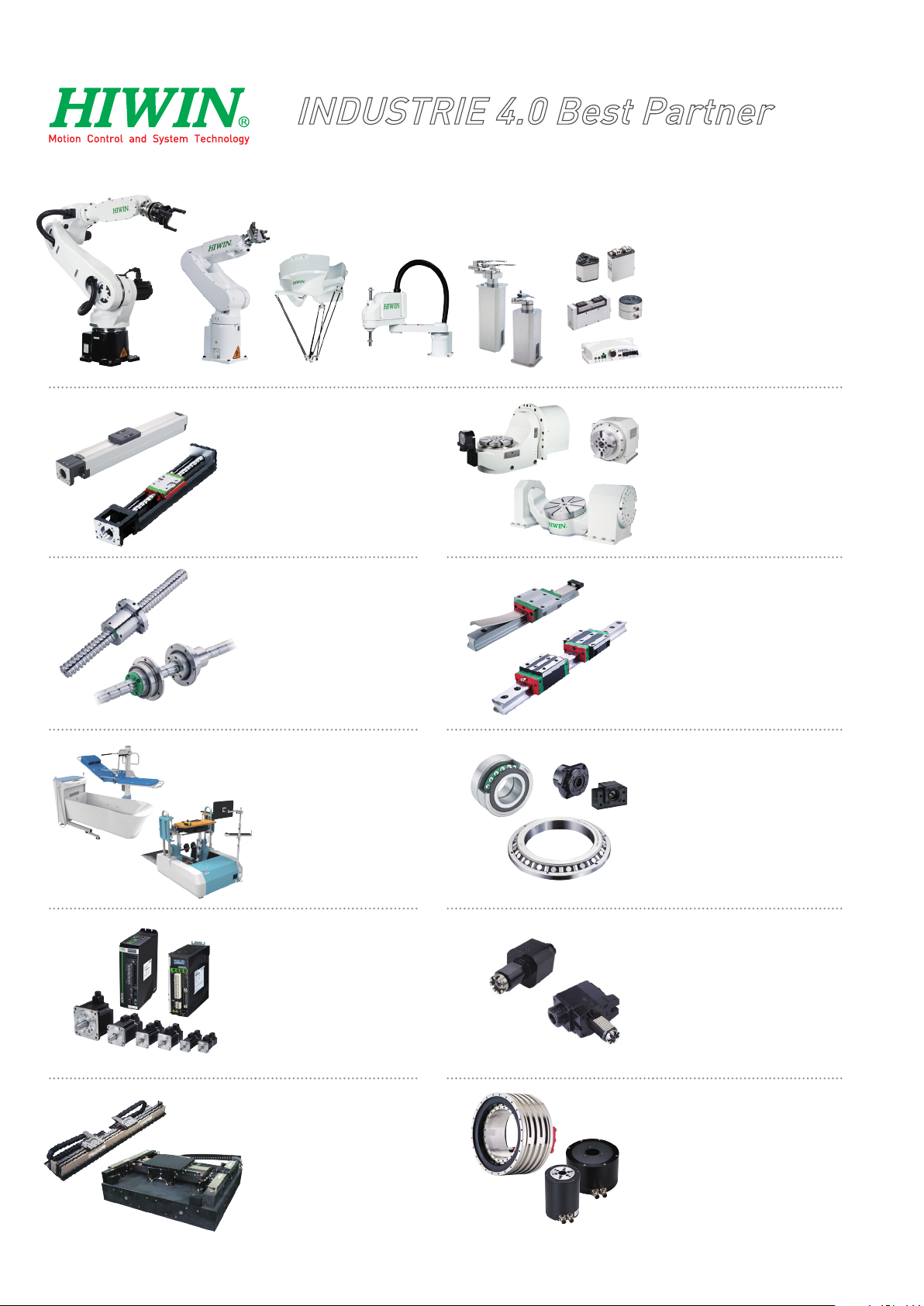
INDUSTRIE 4.0 Best Partner
Multi Axis Robot
Pick-and-place / Assembly /
Array and packaging / Semiconductor /
Electro-Optical industry /
Automotive industry / Food industry
ßArticulated Robot
ßDelta Robot
ßSCARA Robot
ßWafer Robot
ßElectric Gripper
ßIntegrated Electric Gripper
ßRotary Joint
Single Axis Robot
Precision / Semiconductor /
Medical / FPD
ßKK, SK
ßKS, KA
ßKU, KE, KC
Ballscrew
Precision Ground / Rolled
ßSuper S series
ßSuper T series
ßMini Roller
ßEcological & Economical
lubrication Module E2
ßRotating Nut (R1)
ßEnergy-Saving & Thermal-
Controlling (C1)
ßHeavy Load Series (RD)
ßBall Spline
Medical Equipment
Hospital / Rehabilitation centers /
Nursing homes
ßRobotic Gait Training System
ßHygiene System
ßRobotic Endoscope Holder
Direct Drive
Rotary Table
Aerospace / Medical / Automotive industry /
Machine tools / Machinery industry
ßRAB Series
ßRAS Series
ßRCV Series
ßRCH Series
Linear Guideway
Automation / Semiconductor / Medical
ßBall Type--HG, EG, WE, MG, CG
ßQuiet Type--QH, QE, QW, QR
ßOther--RG, E2, PG, SE, RC
Bearing
Machine tools / Robot
ßCrossed Roller Bearings
ßBall Screw Bearings
ßLinear Bearing
ßSupport Unit
AC Servo Motor & Drive
Semiconductor / Packaging machine
/SMT / Food industry / LCD
ßDrives-D1, D1-N, D2T
ßMotors-50W~2000W
Linear Motor
Automated transport / AOI application
/ Precision / Semiconductor
ßIron-core Linear Motor
ßCoreless Linear Motor
ßLinear Turbo Motor LMT
ßPlanar Servo Motor
ßAir Bearing Platform
ßX-Y Stage
ßGantry Systems
Driven Tool Holders
All kinds of turret
ßVDI Systems
Radial Series, Axial Series, MT
ßBMT Systems
DS, NM, GW, FO, MT, OM, MS
Torque Motor
(Direct Drive Motor)
Inspection / Testing equipment /
Machine tools / Robot
ßRotary Tables-TMS,TMY,TMN
ßTMRW Series
ßTMRI Series
C18UE001-1804
Warranty Terms and Conditions
The period of warranty shall commence at the received date of HIWIN product
(hereafter called “product”) and shall cover a period of 12 months. The warranty does
not cover any of the damage and failure resulting from:
The damage caused by using with the production line or the peripheral
equipment not constructed by HIWIN.
Operating method, environment and storage specifications not specifically
recommended in the product manual.
The damage caused by changing installation place, changing working
environment, or improper transfer after being installed by the professional
installer.
Product or peripheral equipment damaged due to collision or accident caused by
improper operation or installation by the unauthorized staff.
Installing non-genuine HIWIN products.
The following conditions are not covered by the warranty:
Product serial number or date of manufacture (month and year) cannot be
verified.
Using non-genuine HIWIN products.
Adding or removing any components into/out the product without authorized.
Any modification of the wiring and the cable of the product.
Any modification of the appearance of the product; removal of the components
inside the product. e.g., remove the outer cover, product drilling or cutting.
Damage caused by any natural disaster. i.e., fire, earthquake, tsunami, lightning,
windstorms and floods, tornado, typhoon, hurricane etc.
HIWIN does not provide any warranty or compensation to all the damage caused by
above-mentioned circumstances unless the user can prove that the product is defective.
For more information towards warranty terms and conditions, please contact the
technician or the dealer who you purchased with.
Improper modification or disassemble the robot might reduce
the robot function, stability or life.
The end-effector or the cable for devices should be installed
1.
Safety Information
Safety Responsibility and Effect
This chapter explains how to use the robot safely. Be sure to read this
C18UE001-1804
and designed by a professional staff to avoid damaging the
robot and robot malfunction.
Please contact the technician for special modification coming
from production line set up.
For the safety reason, any modification for HIWIN product is
strictly prohibited.
Safety Precautions
chapter carefully before using the robot.
The user of the HIWIN industrial robot has responsibility to design and
install the safety device meeting the industrial safety regulations in order to
ensure personal safety.
2.
Description Related to Safety
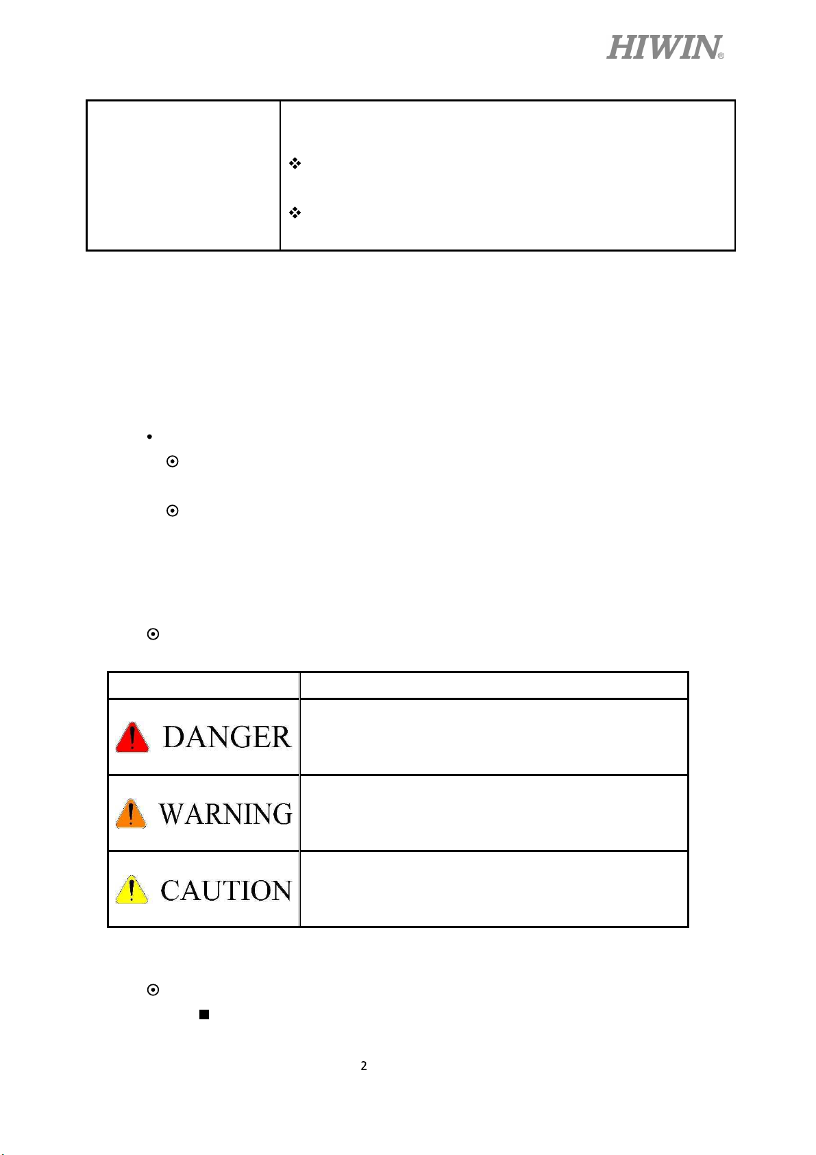
I. Safety Symbols
Carefully read the instructions in the user manual prior to robot use. The
following shows the safety symbols used in this user manual.
Symbol Description
Failure to follow instructions with this symbol may result
in serious hazard or personal injury. Please be sure to
comply with these instructions.
Failure to follow instructions with this symbol may result
in personal injury or product damage. Please be sure to
comply with these instructions.
Failure to follow instructions with this symbol may result
in poor product performance. Please be sure to comply
with these instructions.
II. Working Person
The personnel can be classified as follows
Operator:
3.
C18UE001-1804
Turns robot controller ON/OFF
Starts robot program from operator’s panel
Reset system alarm
Programmer or teaching operator:
Operates the robot
Teaches robot inside the safety fence
Maintenance engineer:
Operates the robot
Teaches robot inside the safety fence
Does maintenance, adjustment, replacement
Programmer and the maintenance engineer must be trained for proper robot
operation.
Warning
3.1 Common Safety Issues
All operating procedures should be assessed by
professional and in compliance with related
industrial safety regulations.
When operating robot, operator needs to wear
safety equipment, such as smock for working
environment, safety shoes and helmets.
When encountering danger or other emergency or
abnormal situation, please press the emergency stop
button immediately and move the arm away with
low speed in manual mode.
When considering safety of the robot, the robot and
the system must be considered at the same time. Be
sure to install safety fence or other safety equipment
and the operator must stand outside the safety fence
while operating the robot.
A safety zone should be established around the
robot with an appropriate safety device to stop the
unauthorized personnel from access.
While installing or removing mechanical
components, be aware of a falling piece which may
cause injury to operator.
C18UE001-1804
Ensure the weight of workpiece does not exceed the
rated load or the tolerable torque. Exceeding these
values could lead to the driver alarm or malfunction
of the robot.
Do not climb on robot.
The personnel installing robot should be trained and
licensed.
To ensure personal safety, robot installation must
comply with this manual and related industrial
safety regulations.
The control cabinet should not be placed near high
voltage or machines that generate electromagnetic
fields to prevent interference that could cause the
robot to deviation or malfunction.
Using non-HIWIN repair components may cause
3.2 Operation
3.3 Maintenance
robot damage or malfunction.
Beware of the heat generated by the controller and
servo motor.
Do not overbend the cable to avoid poor circuit
contact.
Programming should be done outside of the safety
fence. If it is inevitable to enter the safety fence, be
prepared to press the emergency stop button
whenever necessary. Operation should be restricted
at low speed and beware of surrounding safety.
Please contact us if the procedure not specified by
HIWIN is needed.
Please contact us if the replacement of the
component not specified by HIWIN is needed.
Be sure to carry out regular maintenance, otherwise
it will affect the service life of the robot or other
unexpected danger.
3.4 End Effector
C18UE001-1804
Prior to repair and maintenance, please turn off
power supply.
Maintenance and repair should be performed by a
qualified operator with a complete understanding of
the entire system to avoid risk of robot damage and
personal injury.
When replacing the components, avoid foreign
material going into the robot.
More attention must be paid to the design of the end
effector to prevent power loss or any other errors
that could lead to workpiece falling or damage.
The tool-type end effector is usually equipped with
high voltage, high temperature and active rotary
3.5 Pneumatic, Hydraulic System
3.6 Emergency Stop
shaft. Special attention should be paid to the
operating safety.
The end effector should be mounted firmly on the
robot to avoid workpiece release during operation
which may cause personal injury or hazard.
The end effector may be equipped with its own
control unit. Be sure the control unit does not
interfere with robot operation.
When using the pneumatic or hydraulic system, the
gripped workpiece may fall due to insufficient
pressure or gravity.
The robot or other control component should have
at least one device for immediate halt of n function,
such as an emergency stop switch.
The emergency stop button must be installed in an
easily accessible location for quick stop.
While executing an emergency stop, power to the
C18UE001-1804
servo motor will be cut, and all movements will be
stopped. And the control system will be shut down.
Emergency stop should be reset if the restoration of
operating procedure is wanted.
Avoid using emergency stop to replace a normal
stop procedure. This could lead to unnecessary loss
to robot.
C18UE001-1804
1.Transportation and Installation
1.1 Transportation
1.2 Installation
1.3 Connection with the Controller
1.4 Grounding
1.5 Operating Ambient Conditions
1.6 Standard and Optional Equipment List
2.Basic Specifications
2.1 Description of Serial Number
2.2 Labels
2.3 Robot Specifications
Content
2.4 Outer Dimensions and Motion Range
2.5 Wrist Moment Conditions
3.Equipment Mounting Surface and Interface
3.1 Mounting Surface for End Effector
3.2 Pneumatic Interface
3.3 I/O Interface
4.Zero-Position
4.1 Zero Position Setting
5.Maintenance and Inspection
5.1 Periodic Inspection Items
5.2 Repair
5.2.1 Backup Batteries Replacement
5.2.2 Timing Belt Replacement
5.2.3 Grease Replenishment

C18UE001-1804
Version Date Product Note
1.0.0 2017.12.18
RT605-710-GB
RT605-710-GB
First edition
Manual specification updated
2.0.0 2018.01.08
RT605-909-GB
RT605-909-GB

C18UE001-1804
1. Transportation and Installation
1.1 Transportation
Sling can be used to transport the robot. The transportation procedure is as follows:
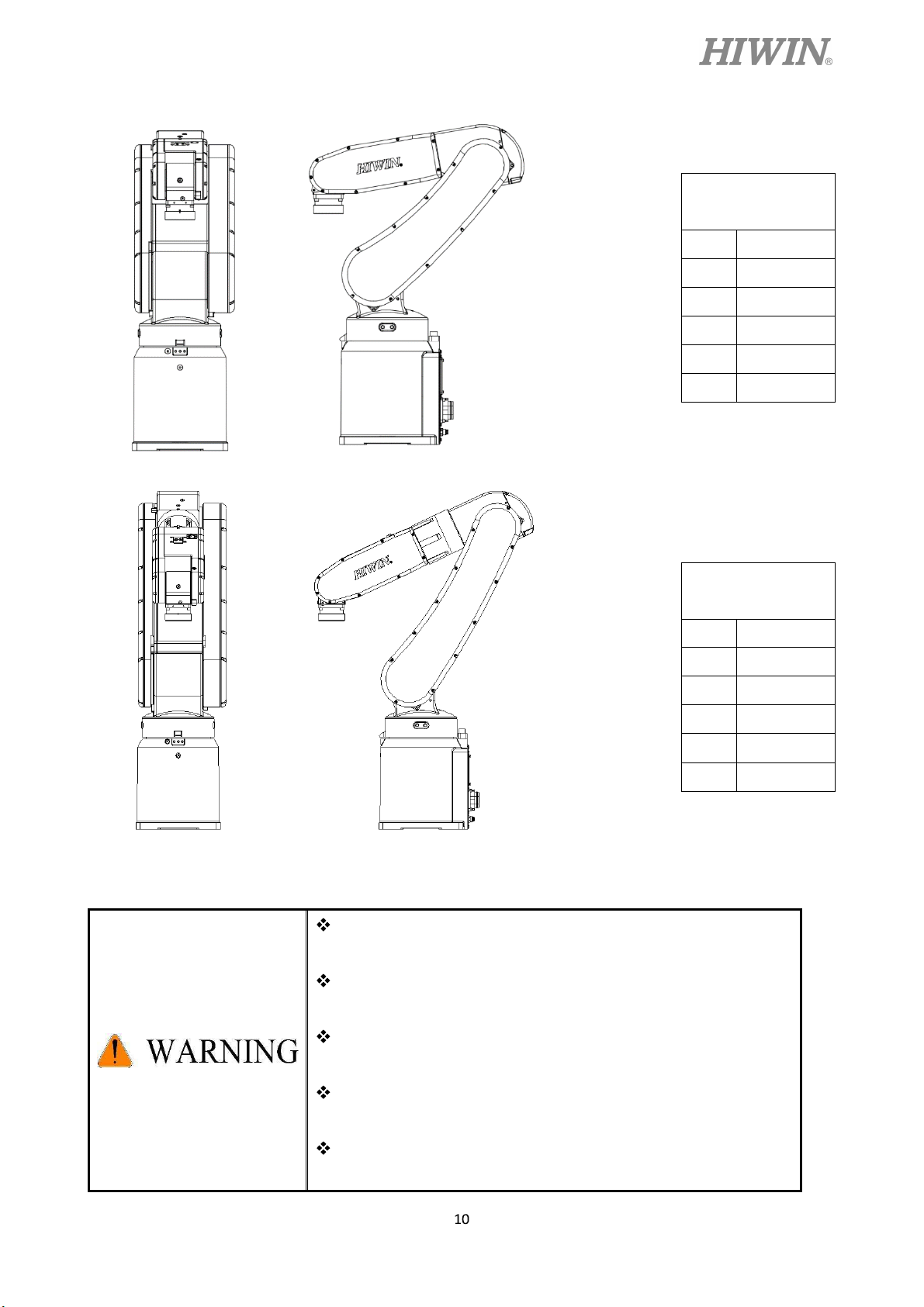
Step1. Move the robot into its transport posture and the angle of each joint is shown in the table
of Figure 1-1.
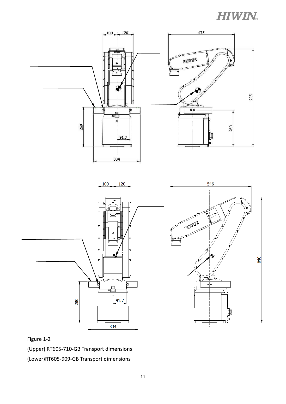
Step2. Secure the suspension plate to the robot with four M8×1.25P×12L screws as shown in
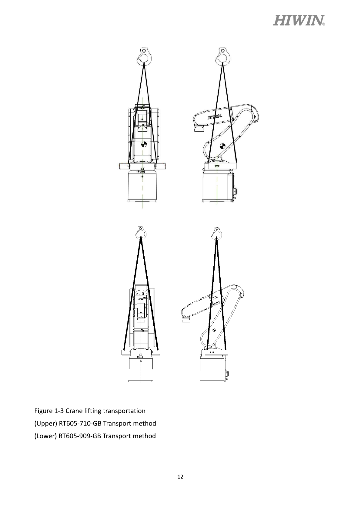
Figure 1-2. Make the sling go through the suspension plate to keep the center of gravity
under the hanging point shown as Figure 1-3. Please ensure the robot is in stable
condition to avoid overturning.
Step3. Move the robot to the desired position by using sling.
Step4. Remove the suspension plate.
C18UE001-1804
RT605-710-GB
Transport posture
J1 0°
J2 45°
J3 -55°
J4 0°
J5 -80°
J6 0°
RT605-909-GB
Transport posture
J1 0°
J2 30°
J3 -55°
J4 0°
J5 -65°
J6 0°
Figure 1-1 Transport posture
Before carrying the robot, be sure to remove the end
effector which changes the center of gravity.
Please keep stable, slow down and avoid excessive
vibration or shock during transportation.
While placing the robot be sure to avoid the robot and the
installation surface collision.
After removing the suspension plate, please maintain it
properly for re-transportation.
Before operation, remove the suspension plate to avoid
danger.
C18UE001-1804
Hexagon socket cap screw
M8x1.25Px12L
Suspension plate
Center of
gravity
Center of
gravity
Hexagon socket cap screw
M8x1.25Px12L
Suspension plate
Center of
gravity
Center of
gravity
C18UE001-1804
C18UE001-1804
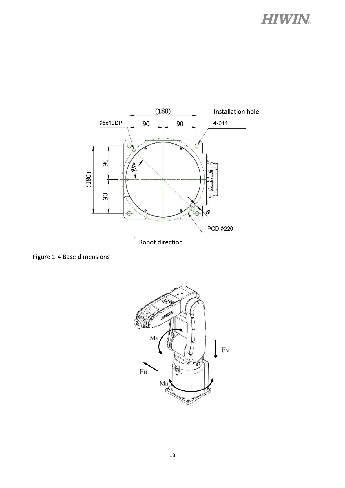
1.2 Installation
Figure 1-4 shows the installation dimensions of the robot. According to the dimensions, fix
the robot on the installation surface with M10 screws. Figure 1-5, table 1-1 and table 1-2 show
the forces and moments acting on the installation surface during operation. The strength of
surface must be considered when installing the robot.
Figure 1-5 Forces and moments acting on the installation surface
C18UE001-1804
Table 1-1 RT605-710-GB Value of forces and moments acting on the installation surface
Vertical moment
Vertical force
Horizontal moment
Horizontal force
Mv (Nm)
Fv (N)
MH (Nm)
Stop 144 441 0 0
Acceleration
382 1009 149 456
/Deceleration
Power cut stop
462 1199 248 760
Table 1-2 RT605-909-GB Value of forces and moments acting on the installation surface
Vertical moment
Vertical force
Horizontal moment
Horizontal force
Mv (Nm)
Fv (N)
MH (Nm)
Stop 160 490 0 0
FH (N)
FH (N)
Acceleration
/Deceleration
Power cut stop
526 1205 244 748
660 1467 407 1246
Ensure the installation surface is smooth plane which is
recommended to be 6.3a or less for the roughness. If the
installation surface is rough, the robot could produce the
position shift during the operation.
Ensure the position of the installation surface for the robot will
not shift owing to the movement.
Ensure the strength of the installation surface for the robot will
not be damaged owing to the movement.
 Loading...