

INDUSTRIE 4.0 Best Partner
Multi Axis Robot
Pick-and-place / Assembly /
Array and packaging / Semiconductor /
Electro-Optical industry /
Automotive industry / Food industry
ßArticulated Robot
ßDelta Robot
ßSCARA Robot
ßWafer Robot
ßElectric Gripper
ßIntegrated Electric Gripper
ßRotary Joint
Single Axis Robot
Precision / Semiconductor /
Medical / FPD
ßKK, SK
ßKS, KA
ßKU, KE, KC
Ballscrew
Precision Ground / Rolled
ßSuper S series
ßSuper T series
ßMini Roller
ßEcological & Economical
lubrication Module E2
ßRotating Nut (R1)
ßEnergy-Saving & Thermal-
Controlling (C1)
ßHeavy Load Series (RD)
ßBall Spline
Medical Equipment
Hospital / Rehabilitation centers /
Nursing homes
ßRobotic Gait Training System
ßHygiene System
ßRobotic Endoscope Holder
Direct Drive
Rotary Table
Aerospace / Medical / Automotive industry /
Machine tools / Machinery industry
ßRAB Series
ßRAS Series
ßRCV Series
ßRCH Series
Linear Guideway
Automation / Semiconductor / Medical
ßBall Type--HG, EG, WE, MG, CG
ßQuiet Type--QH, QE, QW, QR
ßOther--RG, E2, PG, SE, RC
Bearing
Machine tools / Robot
ßCrossed Roller Bearings
ßBall Screw Bearings
ßLinear Bearing
ßSupport Unit
AC Servo Motor & Drive
Semiconductor / Packaging machine
/SMT / Food industry / LCD
ßDrives-D1, D1-N, D2T
ßMotors-50W~2000W
Linear Motor
Automated transport / AOI application
/ Precision / Semiconductor
ßIron-core Linear Motor
ßCoreless Linear Motor
ßLinear Turbo Motor LMT
ßPlanar Servo Motor
ßAir Bearing Platform
ßX-Y Stage
ßGantry Systems
Driven Tool Holders
All kinds of turret
ßVDI Systems
Radial Series, Axial Series, MT
ßBMT Systems
DS, NM, GW, FO, MT, OM, MS
Torque Motor
(Direct Drive Motor)
Inspection / Testing equipment /
Machine tools / Robot
ßRotary Tables-TMS,TMY,TMN
ßTMRW Series
ßTMRI Series
C19UE101-1804
1.
Safety Information
Safety Responsibility and Effect
This safety information neither contains how to design, install and
Users of HIWIN robot have the responsibility to design and install
In compliance with the safety information on industrial robot
Safety and Notice
run a complete workstation or production line, nor ensure the whole
system safety. In order to guarantee personal safety, all machines
must be designed and installed according to the industrial safety
regulations.
the safety devices in compliance with the industrial safety
regulations, used to protect personal safety.
HIWIN robot will not
occur any safety accident.
Safety Operation Principle
Emergency Stop button (on Teach Pendant or from external
emergency stop switch) must be pressed before turning off the
power, and then disconnect the power switch.
After turning off the power switch, the operator must wait for green
indicator (PC indicator) to disappear then remove or turn off the
main power.
After turning off the power switch, do not restart it immediately.
Please wait for 30 seconds to restart.
The controller contains lead-acid battery. It may cause the lack of
electricity by natural wearing and will not be able to be turned on
successfully. If it is idle for a long time, please maintain the power
transmission at least every 3 months and keep it on lasting for 24
hours. Or take out the battery and keep the voltage of the battery
over 13V.
When the voltage of the battery is too low causing failure to turn on
the controller, please take out the battery and charge it with the
external power source until the voltage is over 13V. Or replace the
battery with a new one and then try to turn it on again.
Flipping it 90 degrees on the side or turning it over 180 degrees are
forbidden while installing the controller. This is to protect the
internal battery component.
While connecting to the external I/O or the signal, please operate in
the condition that the power switch is turned off to prevent from a
shortcut caused by mistaken touch in the process, and resulting in
damage.
2. Description Related to Safety
I. Safety Symbol
Please carefully read and make sure to follow this manual before
operating the robot. The following are the safety symbol used in this
manual.
C19UE101-1804
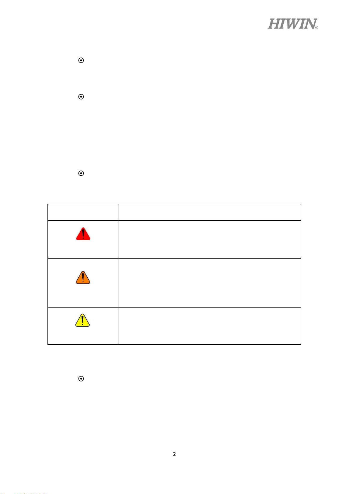
Symbol Description
DANGER
WARNING
CAUTION
II. Safety Grade
The following symbols are frequently used for safety notice. Please
Failure to follow the description of this symbol will cause
serious personal injury. Please make sure to follow those
requirements to ensure safety.
Failure to follow the description of this symbol will cause
personal injury or product damage. In order to guarantee
the safe use of this product, please follow this regulation
strictly.
Failure to follow the description of this symbol will result
in improper operation. In order to guarantee the safe use
of this product, please make sure to follow this regulation.
carefully read the following notices and always follow them before
operating the robot.
C19UE101-1804
Do not operate the machine in potentially explosive
environment.
Do not store the machine in the environment with
corrosive gas, with flammable gas or close to the
flammable object.
Do not operate the machine in the environment with
moisture, water or grease.
Do not operate the machine at the place where
vibration or the strong impact occurs.
Do not immerse the electric wires into grease or
water.
Do not connect or operate the machine with wet
hands.
DANGER
Please ensure the controller is grounded.
Keep hands away from the inner part of the controller
while it is connecting to the power or during
operating.
Do not touch the heat sink, regenerative resistance,
the power supply or the computer inside the
controller. While it is operating due to its high
temperature.
Be sure power is disconnected prior to move, connect,
check and maintain the controller, and ensure to
operate under the condition of no electrical shock risk.
The emergency stop switch must be installed in an
appropriate location where it can be operated easily.
When the robot acts abnormally, it could immediately
stop the robot from causing serious safety accident.
Do not open the controller cover without permission.
Do not stand on the product or put heavy objects on
it.
C19UE101-1804
WARNING
Do not block the vent or put foreign objects into it.
Please ensure the controller is fixed on the base.
Do not pull the connector violently or twist the
electric wires excessively.
Do not frequently switch the power switch and the
control button.
Please ensure that the robot, the emergency stop
switch and the controller are functioning properly
before performing any work.
Do not turn off the power switch during the
operation.
Do not open, modify, disassemble and maintain the
machine without permission.
The power must be disconnected when the machine
does not operate in a long time.
All operations must be executed by the trained staff.
The controller must be kept away from high voltage
When the robot is used to demonstrate, the operation
CAUTION
Do not turn off the power of the controller when
or components that may generate electromagnetic
field which will lead to robot malfunction or damage.
speed should keep low and always keep an eye on the
operating condition to prevent the workpiece from
dropping or causing danger to operator.
modifying the program or parameter. Otherwise, the
data stored in the controller will be damaged or lost.

C19UE101-1804
3.
Safety Notice
I. Safety Risk
i. Installation
Ordinary Risk
Risk without electric shock
The installation procedures must follow this manual.
The emergency stop switch must be installed in an appropriate
location where it can be operated easily, so that the operator can
immediately stop the robot system in an emergency.
The person who installs the robot must be trained and
authorized.
Always follow the installation and safety requirements
described in this manual to ensure personal safety.
A safety area must be set outside the working range of the robot,
and a safety device must be used to prevent the personnel
entering without permission.
After the brake of a servo motor is released, the robot will move
due to the gravity and it may injure the operator.
When installing or disassembling any mechanical parts, be
aware of falling parts which may injure the operator.
Be aware of high temperature produced by the controller.
Do not allow any action of climbing on the robot.
ii. End effector
The end effector can be classified as two types:
A. Gripper: Used to load and unload, such as pneumatic
B. Tool: Used to process, such as welding, cutting and
The gripper-type end effector should prevent the workpiece
from dropping or damaging when the robot experiences a power
gripper, electric gripper and vacuum sucker.
surface treatment.
error or other errors. More attention should be paid at the design
stage.
The end effector could be equipped with the control unit. The
position must be noted to avoid the robot interference when the
end effector is installed.
The tool-type end effector is usually equipped
C19UE101-1804
WARNING
iii.
Pneumatic and Hydraulic Systems
with high voltage, high temperature or active
shaft. Special attention should be paid during the
operation.
More attention should be paid to the pressure remained in the
pneumatic and hydraulic systems after the power is
disconnected.
The internal pressure must be released before the pneumatic and
hydraulic systems are maintained.
When the pneumatic and hydraulic systems are operated, the
clamped workpiece could drop owing to the insufficient
pressure or gravity.
The pneumatic and hydraulic systems must be equipped with
the relief valve, so that the operator can be applied in an
WARNING
iv.
Risk caused by the working environment
emergency.
More attention should be paid to the pressure in
the pneumatic and hydraulic systems which are
usually several times more than the atmosphere
pressure.
The industrial robots can be applied for the different industrial
environments.
All operating procedures must be specified by the professional
evaluation and according to the industrial safety regulations.
Maintenance must be conducted by the trained personnel who
clearly understand the procedures for the whole system and
other possible risks.

C19UE101-1804
When the operating procedures are interrupted, the special
attention should be paid during the troubleshooting.
II.
Emergency Stop
Emergency Stop Definition
When the emergency stop is executed, the power supplied from
the servo driver to the motor will be disconnected and all
actions will be stopped.
If the procedures are recovered, the emergency stop switch
should be reset.
Avoid using the emergency stop instead of the normal stop
procedure to shut down the robot system. Otherwise, it may
cause unnecessary damage to the robot system.
Emergency Stop Switch
The HIWIN robot is equipped with two emergency stop
switches, where one is installed on the teach pendant and the
other is directly connected to the controller via the cable. If
additional emergency stop switches are required, other
connection can be applied for the same purpose.
Based on the relevant industrial safety regulations, the
emergency stop switch is directly connected to the controller of
the robot via the physical wires.
4. Warranty Terms and Conditions
The period of warranty shall commence at the received date of
of 12 months. The warranty does not cover any of the damage and
failure resulting from:
The damage caused by using with the production line or the
peripheral equipment not constructed by HIWIN.
Operating method, environment and storage specifications
not specifically recommended in the product manual.
The damage caused by changing installation place, changing
working environment, or improper transfer after being
installed by the professional installer.
Product or peripheral equipment damaged due to collision or
C19UE101-1804
accident caused by improper operation or test by the
unauthorized staff.
Installing non-genuine HIWIN products.
The following conditions are not covered by the warranty:
Product serial number or date of manufacture (month and
year) cannot be verified.
Using non-genuine HIWIN products.
Adding or removing any components into/out the product
without authorized.
Any modification of the wiring and the cable of the product.
Any modification of the appearance of the product; removal
of the components inside the product. e.g., removal of the
cover, product drilling or cutting.
Damage caused by any natural disaster. i.e., fire, earthquake,
tsunami, lightning, windstorms, floods, tornado, typhoon and
hurricane etc.
C19UE101-1804
HIWIN does not provide any warranty or compensation to all the
damage caused by above-mentioned circumstances unless the user can
prove that the product is defective.
For more information towards warranty terms and conditions, please
contact the technician or the dealer who you purchased with.
Improper modification or disassemble the
robot might reduce the robot function,
stability or lifespan.
The end-effector or the cable for devices
should be installed and designed by a
professional staff to avoid damaging the robot
or robot malfunction.
WARNING
Please contact the technical support for
special modification coming from production
line set up.
For the safety reason, any modification for
HIWIN product is strictly prohibited.
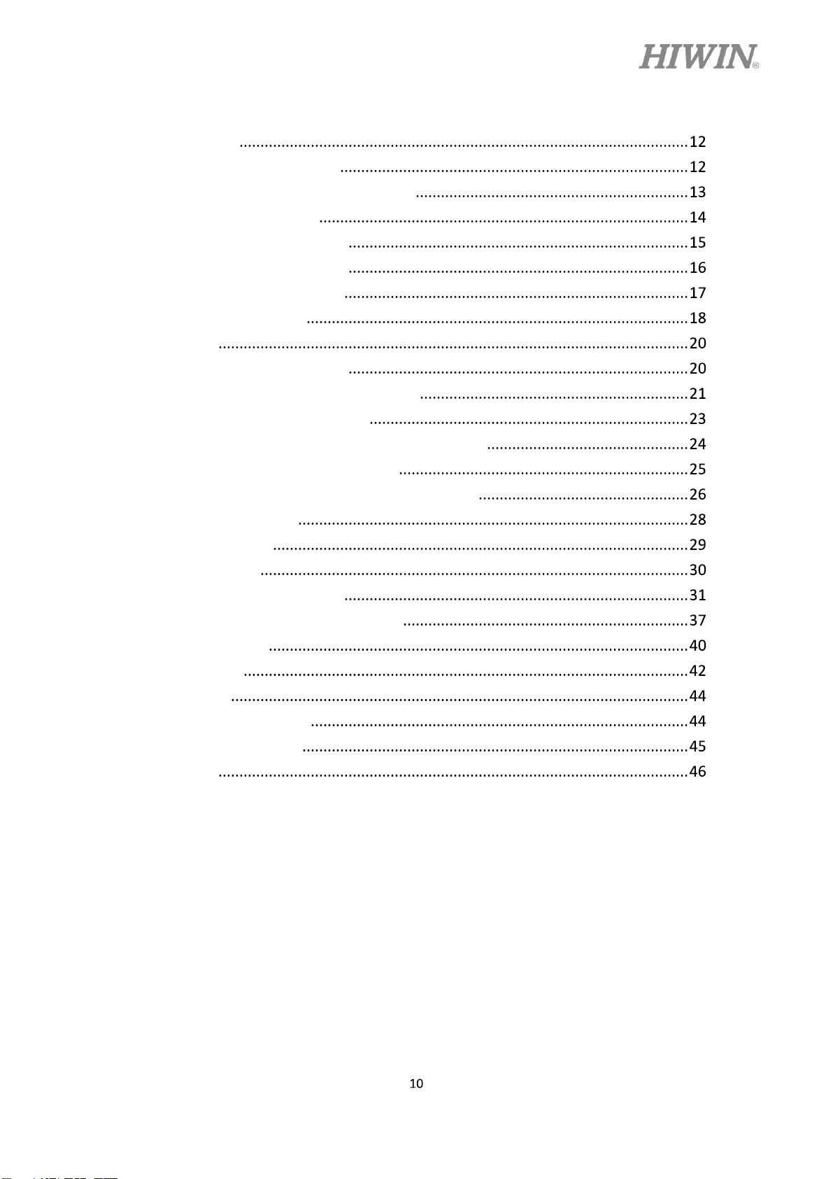
Content
1. Specifications
1.1 Standard Specification
1.2 Standard and Optional Equipment
1.3 Serial Specification
1.4 Appearance Dimensions
1.5 Appearance Component
1.6 Operating Environment
1.7 Sticker and Label
2. Installation
2.1 Installation Dimensions
2.2 Multifunctional Installation Frame
2.3 Basic Connection Structure
2.4 Instruction of Controller ON/OFF Procedure
2.5 Motor Cable Connection (CN2)
C19UE101-1804
2.6 Emergency Stop Switch Connection (CN3)
3. External Input/ Output
3.1 Function I/O
3.2 Digital I/O
3.3 Example of Connection
3.4 Encoder Capture Module (CN5)
3.5 RS-232 Port
4. Teach Pendant
5. Maintenance
5.1 Lead-Acid Battery
5.2 Fan Cotton Filter
5.3 Fuse
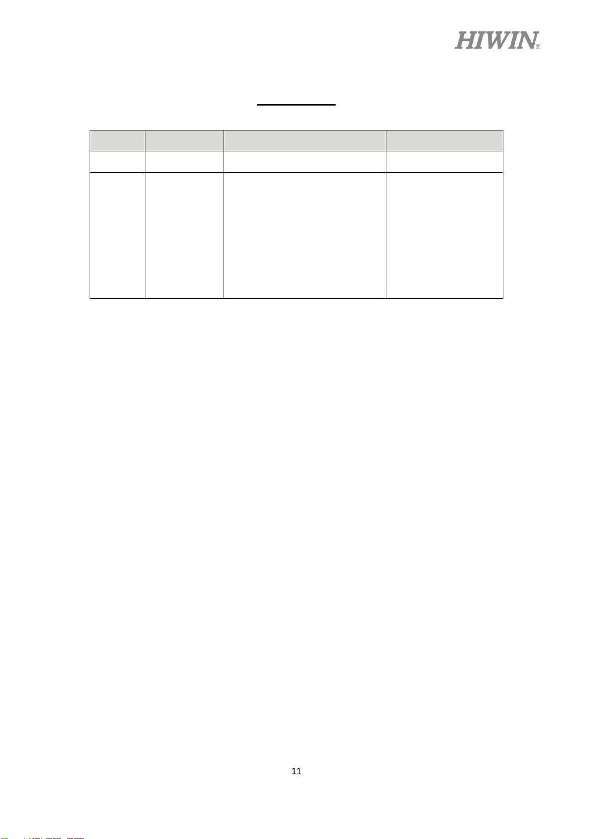
Version Update
Version Date Applicable Scope Note
1.0.0 2018.01.08 RCD403-GB First release
1. Add leakage
current mark
2. Modify 3.4
C19UE101-1804
1.0.1 2018.03.05 RCD403-GB
Encoder Capture
Module
3. Add 2.6 & 3
warning sign
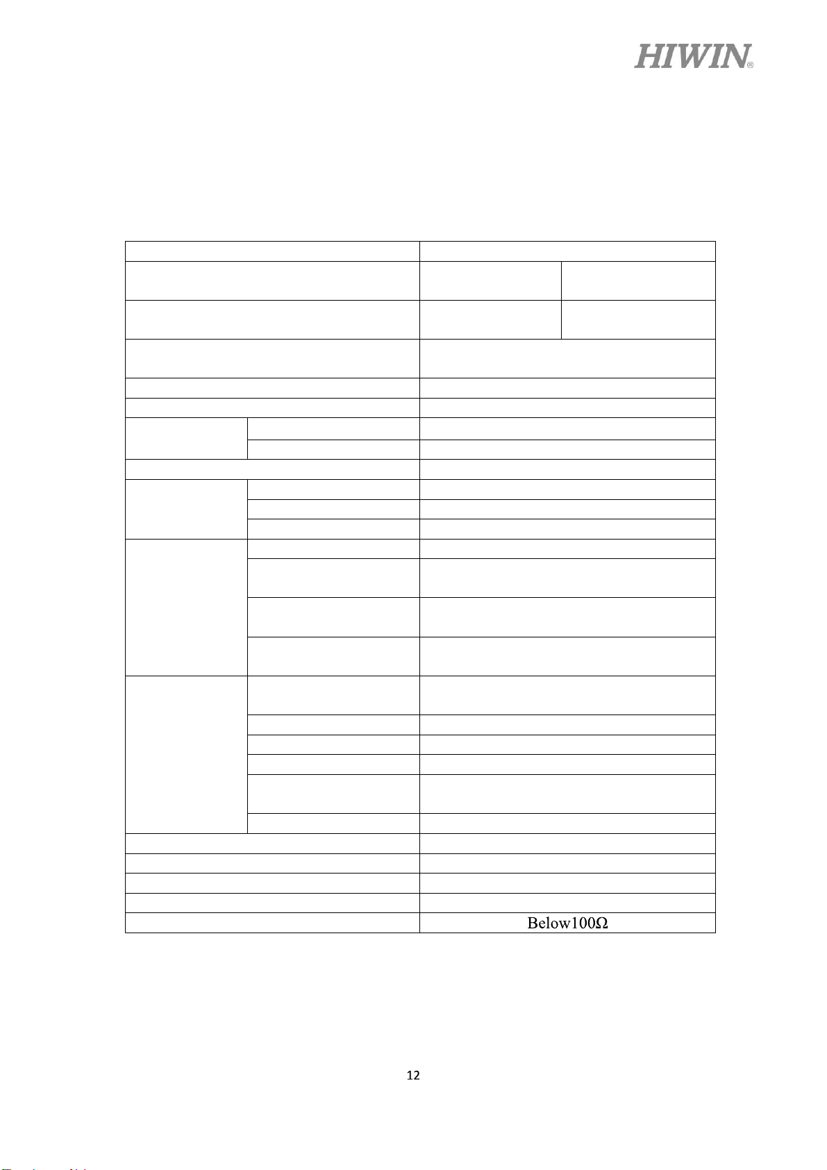
1. Specifications
1.1 Standard Specification
The following table shows the standard specifications of the robot controller.
Item HIWIN Robot Controller
Model No. RCD403-1100-GB
Controlled Manipulator RD403-1100-GB
Positioning control
Joint control AC servo control
Operating system HRSS
Memory
capacity
Teaching method Teach pendant
Communication
interface
External I/O
Power
Weight (kg) 34
IP grade 20
Temperature range for workplaces (oC) 0~45
Relative humidity (%RH) 20~75 (non-condensing)
Grounding
Fixed point 5000
Step number 10000
RS232 1
Ethernet 2
USB 2
Emergency stop input Input : 1
Function I/O
Digital I/O
Encoder capture
module
Input power range
(VAC)
Power capacity (KVA) 1.5
Power frequency (HZ) 50/60
Voltage drop (msec) 10 or less
Rating output current
(A)
Current leakage (mA) 30
PTP (point-to-point)
CP (continuous path)
Output : 24
Three Phase AC 200-240
RCD403-1100-PR-
GB
RD403-1100-PR-
GB
Input : 8
Output : 8
Input : 24
4 Channel
4.5
C19UE101-1804
C19UE101-1804
1.2 Standard and Optional Equipment
The following table shows the items of the standard equipment for the robot
controller.
Item HIWIN Part No. Remark
CN1, Main Power Cable 4C7018Y1 Refer to CH2.3
CN2, Motor Power Signal Cable 5M AH301A01 Refer to CH2.5
Connector Accessory Kit 4C201M91
The following table shows the items of robot controller optional equipment.
Item HIWIN Part No. Remark
Teach Pendant AH301401 Refer to CH 4
CN3 Emergency Stop Switch Unit 5M 4C7013F2 Refer to CH 2.6
External I/O Wiring Kit 4C201DY1
Cotton Filter 4657003Y Refer to CH 5.2
Lead-Acid Battery 462C0097 Refer to CH 5.1
Refer to CH 2.6
and CH3
Refer to CH 3
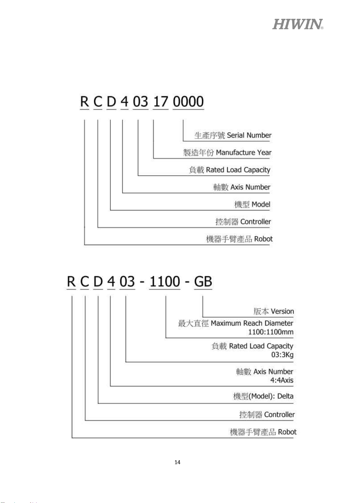
1.3 Serial Specification
Serial Number:
C19UE101-1804
Model Number:

1.4 Appearance Dimensions
C19UE101-1804
The following show the appearance dimensions of the robot controller (unit: mm).
As a complete installation dimension, some space
CAUTION
needs to be reserved for the cables. Please refer to
CH2.1.

1.5 Appearance Component
The function of each connector outside the controller
C19UE101-1804

No. Item Description
1 Power Switch Switch power ON/OFF
2 Main Power Source Inlet three phase AC220V
3 Motor Connector (CN2) Connect robot controller to the robot
manipulator
C19UE101-1804
4 Teach Pendant Connector
(CN4)
5 Emergency Stop Connector
(CN3)
6 Network Connector Ethernet signal transmission
7 USB Connector USB signal transmission
8 RS232 Connector RS232 signal transmission
9 I/O Connector I/O signal transmission
10 Controller Power Indicator
Green Light
11. Encoder Capture Connector
(CN5)
Teach pendant signal transmission
Connect to external emergency stop device
Display ON/OFF status
Capture external encoder value
1.6 Operating Environment
The robot controller employs the IEC protection rating as IP20 (open). In addition, IP20
indicates the protection rating for the solid, not for grease and water.
The controller should not be placed at the
environment with moisture, with high
temperature, under direct sunlight or potentially
explosive environment.
Please keep the controller away from the strong
WARNING
electric field or the magnetic field.
Because the vents are set on the right side of the
controller, please ensure a space of 50mm from
the right.
Please place the controller at flat surface, and
avoid shaking.

C19UE101-1804
1.7 Sticker and Label
The following shows the appearance stickers and labels on the robot controller.

C19UE101-1804
No. Illustration Description
1
2
3
4
Controller specification
Beware of electric shock
Grounding
Transport by multiple people
5
Danger: authorized professionals
only

C19UE101-1804
2. Installation
2.1 Installation Dimensions
The following shows the connector installation space. Please reserve some space for
the connecting wires to avoid interference as they bend. ( unit: mm)
CAUTION
Controller should keep upright while installing as
the illustration shows. Flipping it 90 degrees on the
side and turning it over 180 degrees are forbidden
while installing the controller. This is to protect the
internal battery component.

C19UE101-1804
2.2 Multifunctional Installation Frame
This controller is attached with two groups of multifunctional fixing frame while
delivering (as shown below). The fixing frame can be installed on the controller
with the handle, used for transportation. Or the controller can be fixed on other
machines to use. The assembly method of the fixing frame and the handle is shown
below. The specification of the screws is M6X1PX8L flat-head screw.
Multifunctional fixing frame can be installed on the controller. The assembly drawing
is shown below. The specification of the screws is M6X1PX8L.

C19UE101-1804
Multifunctional fixing frame can be installed under the controller. The assembly
drawing is shown below. The specification of the screws is M6X1PX8L. This
configuration is convenient for the operator to fix the controller on other machines.
The corresponding dimensions of multifunctional fixing frame

C19UE101-1804
2.3 Basic Connection Structure
The picture below is an example of basic connection structure. This controller needs to
be supplied with single-phase AC200-240V, and the ground connection should be
separated from main power breaker. Do not connect the ground by devices or system
ground, the best way is to connect to power ground directly, and high-quality wires
which diameters are 14AWG or more should be used. The power can be turned on and
tested after connecting the main components mentioned below.
No. Item
1 CN1 Main Power Cable
2 CN2 Motor Signal Cable
3 CN3 Emergency Stop Switch
4 CN4 Teach Pendant

Do not connect any switch and breaker to the
ground wire.
C19UE101-1804
Please ensure the robot is firmly installed before
CAUTION
starting the operation test to prevent the robot
topples during the test.
2.4 Instruction of Controller ON/OFF Procedure
Item Illustration Instruction
Controller ON:
After the power is connected, turn the
Controller OFF:
(1) Operate the robot to a safe posture,
and then stop the motion.
Power
Switch
(2) Press the emergency stop button.
(3) Turn the power switch on the
WARNING
the controller starts its shut down
procedure. Before cutting off the
power, make sure the controller is
entirely turned off. (Refer to CH1.4,
wait for the indicator [10] to
disappear)
If you want to stop a moving robot, you should go
through the normal procedure and press the stop
button instead of the emergency stop.
Please stop the robot and press the emergency stop
button before turning it off. Directly cut off the
power while robot is moving may cause an
unexpected danger.

2.5 Motor Cable Connection (CN2)
Description:
The motor cable connects the robot and the
controller with a 5m cable.
Connection method:
The motor connection port on the
controller is CN2 connector
which is designed mistake-
proofing. If it cannot be plugged
C19UE101-1804
in, please rotate and connect it
again.
Plug the motor cable into CN2
connector, and buckle up the
safety lock indeed.
Plug the connector in the direction parallel to the
WARNING
pins to avoid the internal pins being crooked and
deformed.
According to different operating condition, the
temperature of the cable would rise slightly.
Remove plastic cover before connection.
Please avoid severe impact while installation.

C19UE101-1804
cause a severe damage or loss of life and property.
2.6 Emergency Stop Switch Connection (CN3)
Description:
Connector CN3 is a female DSUB-15 connector for
emergency stop.
Emergency stop switch (optional equipment) is a button box
with a 5m wire. It should be placed at the position, which is
easy to reach. DSUB-15 soldering connector is included in
the connector kit.
Emergency stop switch wiring diagram
Controller emergency stop connector is a dual circuit contact, which should be
connected with an external dual circuit emergency stop device additionally. This
device should be a dry contact (uncharged) switch. Ensure the connector is connected
correctly and the emergency stop device is accessible to the operator before the robot
functions.
The emergency stop device must be connected with
the controller and be placed at the position
accessible to operator. Wrong method of using can
DANGER

Connection Method:
The connector of emergency stop
device on controller is CN3 which is
designed mistake-proofing. If it
cannot be plugged in, please rotate
and connect it again.
Plug the connector into CN3 and
C19UE101-1804
secure the screws indeed.
CAUTION
Please ensure this emergency stop switch and
the emergency stop on the teach pendant are
all reset before the robot functions.
The external device connected to the
emergency stop switch circuit should be dry
contact (uncharged) switch. The charged
circuit is forbidden.

C19UE101-1804
3. External Input/ Output
Description:
External Input/ Output consists of two DSUB-37, including FI8/FO8 and DI24/DO24.
An external I/O wiring kit (optional equipment) contains connecting wire and
terminal block. Connector kit contains DSUB-37 soldering connector. External I/O
expansion module (optional equipment) can be expanded 16 more input and 16 more
output.
There are two types of controller external I/O:
(1) Function I/O (FI/O) specific function I/O
(2) Digital I/O (DI/O)

C19UE101-1804
3.1 Function I/O
Description:
Standard equipment has function I/O of 8IN/8OUT, which are all in the D37PIN-1
connector.
Function I/O List
INPUT
Pin Parameter Function
2 START Execute program
3 HOLD Pause program
4 STOP Stop program
5 ENBL Enable Function I/O
6 RSR1/PNS1 Robot service request 1 / program selection 1
7 RSR2/PNS2 Robot service request 2 / program selection 2
8 RSR3/PNS3 Robot service request 3 / program selection 3
9 RSR4/PNS4 Robot service request 4 / program selection 4
OUTPUT
Pin Parameter Function
21 RUN Program running
22 HELD Program pausing
23 FAULT Controller failure
24 READY Controller ready
25 ACK1/SNO1 RSR 1 feedback signal / selection program No. 1
26 ACK2/SNO2 RSR 2 feedback signal / selection program No. 2
27 ACK3/SNO3 RSR 3 feedback signal / selection program No. 3
28 ACK4/SNO4 RSR 4 feedback signal / selection program No. 4

3.2 Digital I/O
Description:
Standard equipment has 24IN/24OUT digital I/O, distributed in D37PIN-1 and
D37PIN-2 connectors.
Digital I/O List
C19UE101-1804
D37PIN-1
Pin Parameter Pin Parameter
10 DI[1] 29 DO[1] 2 DI[9] 21 DO[9]
11 DI[2] 30 DO[2] 3 DI[10] 22 DO[10]
12 DI[3] 31 DO[3] 4 DI[11] 23 DO[11]
13 DI[4] 32 DO[4] 5 DI[12] 24 DO[12]
14 DI[5] 33 DO[5] 6 DI[13] 25 DO[13]
15 DI[6] 34 DO [6] 7 DI[14] 26 DO[14]
16 DI[7] 35 DO [7] 8 DI[15] 27 DO[15]
17 DI[8] 36 DO [8] 9 DI[16] 28 DO[16]
10 DI[17] 29 DO[17]
11 DI[18] 30 DO[18]
12 DI[19] 31 DO[19]
13 DI[20] 32 DO[20]
14 DI[21] 33 DO[21]
15 DI[22] 34 DO[22]
Pin Parameter Pin Parameter
D37PIN-2
16 DI[23] 35 DO[23]
17 DI[24] 36 DO[24]

C19UE101-1804
The maximum current at the single output
3.3 Example of Connection
1. External OUTPUT are all NPN (current sinking) output and OUTPUT signal is 0V.
Pin20 (0V) and pin37 (24V) are supply voltage for OUTPUT which is supplied by
external power source and the power connection cannot be reversed.
2. External INPUT can be NPN (current sinking) or PNP (current sourcing) input,
adjusted with pin18 (COM). Pin19 (0V) is supply voltage for INPUT which is
supplied by external power source and the power connection cannot be reversed.
3. Pin20 (0V) and pin37 (24V) of OUTPUT in the same DSUB-37 connector are the
supply voltage, which should be connected to the same power supply.
4. Pin 18 (COM) and pin19 (0V) of INPUT in the same DSUB37 connector should be
connected to the same power supply. The COM voltage level, which is the same, cannot
be separated.
5. OUTPUT and INPUT in the same DSUB-37 connector can be connected to different
power supplies to provide reference voltage level.
6. D37PIN-1 and D37PIN-2 can be connected to different power supplies to provide
reference voltage level.
supplied by external output is 100mA.
The OUTPUT supplied by controller is all NPN
output, which cannot be modified. The INPUT
CAUTION
can be modified into NPN or PNP type by
adjusting COM voltage.

D37PIN-1
INPUT: NPN OUTPUT: NPN
C19UE101-1804

D37PIN-1
INPUT: PNP OUTPUT: NPN
C19UE101-1804

D37PIN-2
INPUT: NPN OUTPUT: NPN
C19UC101-1801
34

D37PIN-2
INPUT: PNP OUTPUT: NPN
C19UC101-1801
35

Connection method:
There are two I/O connectors
(DSUB-37) on the controller which is
designed mistake-proofing. If it
cannot be plugged in, please rotate
and connect it again.
C19UC101-1801
Plug the connector in and secure the
screw indeed.
No signal or power supply should be close to or
in contact with any metal case. Wrong method of
using can cause a severe damage or loss of life
DANGER
and property.
To prevent the internal component from damage,
WARNING
any wiring operation must be done only when the
controller is disconnected.
Please make sure the screws on the connector are
CAUTION
secured.
36

C19UC101-1801
3.4 Encoder Capture Module (CN5)
Description:
There are four channels in the encoder, CH1~CH4, the channel Latch signals are
IDI0~IDI3. IDICOM can change the input to NPN or PNP according to operation.
37

Encoder List
maximum current at the single output
C19UC101-1801
Pin Parameter Pin Parameter
1 GND 20 CH1A-
2 CH1A+ 21 CH1B-
3 CH1B+ 22 CH1Z-
4 CH1Z+ 23 CH2A-
5 CH2A+ 24 CH2B-
6 CH2B+ 25 CH2Z-
7 CH2Z+ 26 CH3A-
8 CH3A+ 27 CH3B-
9 CH3B+ 28 CH3Z-
10 CH3Z+ 29 CH4A-
11 CH4A+ 30 CH4B-
12 CH4B+ 31 CH4Z-
13 CH4Z+ 32 GND
14 IDICOM 33 IDI1
15 IDI0 34 IDI3
16 IDI2 35 GND
17 GND
The
supplied is 50mA.
CAUTION
38

C19UC101-1801
Actual Wiring Example
Take OMRON E6B2-CWZ1X as an example, the encoder required extra supply of
5V, CH1 as an input example.
Color Terminal
Brown Power supply(+Vcc)
Blue 0V(common)
Black Output phase A
White Output phase B
Orange Output phase Z
Black/red stripes
White/red stripes
Orange/red stripes
Output phase
Output phase
Output phase
39

3.5 RS-232 Port
Description:
The following figure shows the pin assignment of RS-232 controller.
Pin Description
C19UC101-1801
2 RXD-Receiver
3 TXD-Transmit
5 GND -Ground
The following figure shows the connection method with external device.
40

Connection method:
The I/O connector of controller is
COM1, which is designed mistake-
proofing. If it cannot be plugged in,
please rotate and connect it again.
Plug the connector in and secure the
screw indeed.
C19UC101-1801
No signal or power supply should be close to or
in contact with any metal case. Wrong method of
using can cause a severe damage or loss of life
DANGER
and property.
To prevent the internal component from damage,
WARNING
CAUTION
any wiring operation must be done only when the
controller is disconnected.
Please make sure the screws on the connector are
secured.
41

C19UC101-1801
4. Teach Pendant
Description:
The Teach Pendant provides the program edit, program management and motion
the Emergency Stop Switch and the Enable Switch
Teach Pendant Specification:
Item HIWIN Robot Teach Pendant
Model No. TP02
Dimensions 318x245x107 mm3
Weight 2.5kg
Protection Rating IP20
Display
Resolution 1024x768 pixels
Mode Manual, Auto and Lock
Physical Button
Cable Length 5m
20keys Enable Switch Emergency Stop Switch + Key Switch
It is forbidden to use Teach Pendant in the high
WARNING
dust concentration and high grease concentration
environment since its protection rating is IP20.
To ensure the Teach Pendant functions normally,
any impact and fall are forbidden.
42

Names and functions on Teach Pendant
Button Definition:
C19UC101-1801
No. Item Function Description
1 Emergency Stop
Disable servo and directly stop the robot.
Switch
2 Mode Switch Switch mode among Manu, Auto and Lock
3 XY-Axis T1 Key In the T1 mode, control the movement in XY-axis.
4 Z-Axis T1 Key In the T1 mode, control the movement in Z-axis.
5 Speed Key Adjust the robot speed
6 T1 Key Adjust the value in each axis in the different mode.
When pressing one of the switches, the robot can start
7 Enable Switch
(note 1)
to move; the robot will stop directly when releasing this
switch or pressing it to the end.
*note 1: instruction on enable switch:
In T1 and T2 mode, the enable switch must be held at center position to start the
robot. In Auto mode (AUT) and External Auto mode (EXT), the enable switch
should be held at center position only in the moment it starts, and then release.
The Enable Switch has three positions:
(1) Not pressed
(2) Center position The robot can move and teach
(3) Fully pressed
In addition, the enable switch on both side has the same function.
43

C19UC101-1801
5. Maintenance
5.1 Lead-Acid Battery
-acid battery in the controller which lifespan is about 3 to 5 years.
Please replace the battery when the voltage is too low to turn on or insufficient power.
Battery Replacement Steps:
(1) Remove 11 pieces of M4X0.7PX12L Phillips screws on the cover and remove
the cover.
(2) The battery is located on the right side in the cabinet. Remove the power cable
connected to the battery.
(3) Remove the Volero which fixes the battery; then take out and replace the battery.
(4) After ensuring the battery is fixed, connect it with the power cable. Install the
cover in order after confirm that all the cable is connected securely.
44

C19UC101-1801
After replacement, please ensure the polarities
of battery and power cable are connected
negative (black) to negative.
CAUTION
Ensure to shut down the controller before
replacing the battery.
5.2 Fan Cotton Filter
Every air inlet outside the cabinet contains cotton filter, which has the function of
blocking external foreign material, enhancing the air convection and promoting heat
dissipation. Please decide the frequency of cotton filter replacement according to
working environment.
(1) Remove M4X0.7PX12L Phillips screws on the cover.
(2) Replace internal cotton filter.
(3) Install the cover in order.
correctly; positive (red) to positive and
If poor convection occurs due to the foreign
CAUTION
material accumulated in cotton filter, it may
cause internal overheat and crash.
45

C19UC101-1801
5.3 Fuse
If encountered the following two situations, please try to open the controller cover and
check whether the internal fuse has melted:
1. If unable to start the controller, please follow the steps below to
replace the fuse:
1. Remove 11 pieces of M4X0.7PX12L Phillips screws on the
cover and remove the cover.
2. Check FUSE1, FUSE2, FUSE3 on RCBCDZ023.
3. Remove the protective cover of the fuse, if the fuse is melted,
replace a new fuse.
4. The specification of FUSE1, FUSE2, FUSE3 are 15A 5*20mm
glass fuse.
5. After replacing a new fuse, cover the fuse with protective cover.
6. Check FUSE1 on RCBCDZ033, if the fuse is melted, please
replace a new fuse LITTELFUSE 0297005 5A
7. Close the cover and secure the screws.
46

RCBCDZ023
C19UC101-1801
2. If abnormal sound is produced during the operation of the arm or an
error code 02-02-11 appeared during automatic running
1. Remove 11 pieces of M4X0.7PX12L Phillips screws on the
cover and remove the cover.
2. Check FUSE2 on RCBCDZ033, if the fuse is melted, please
replace a new fuse LITTELFUSE 0297002 2A
3. Close the cover and secure the screws.
RCBCDZ033
47

C19UC101-1801
Make sure the controller is disconnected to the
power supply before replacing the fuse.
WARNING
Replacing fuses with different ampere or other
conductive materials (Iron wire, Iron sheet) are
forbidden.
48


 Loading...