

Hiwin RA605-GB, RB605-GB User Manual
Articulated Robot
- RA605-GB,
RT605-GB
User Manual
Original Instruction
www.hiwin.tw
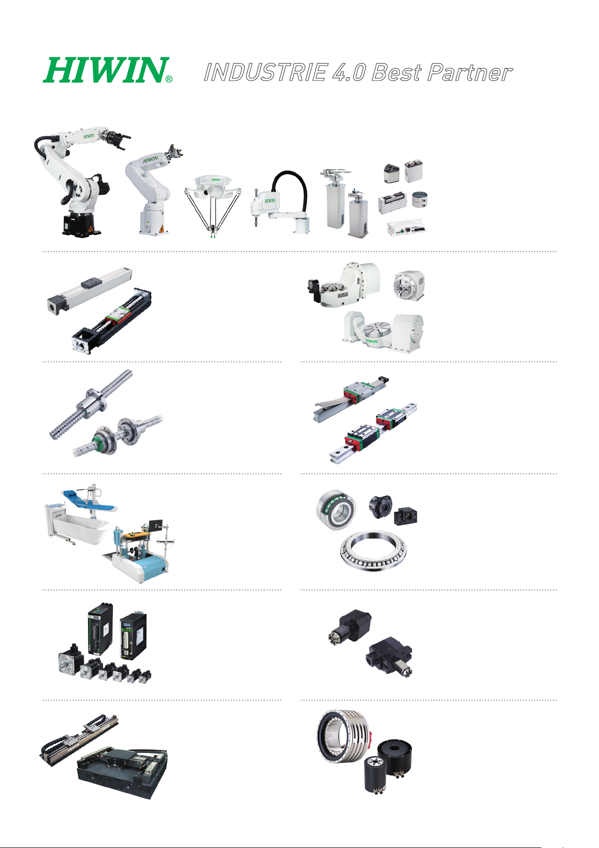
INDUSTRIE 4.0 Best Partner
Multi-Axis Robot
Pick-and-place / Assembly /
Array and packaging / Semiconductor /
Electro-Optical industry /
Automotive industry / Food industry
• Articulated Robot
• Delta Robot
• SCARA Robot
• Wafer Robot
• Electric Gripper
• Integrated Electric Gripper
• Rotary Joint
Single-Axis Robot
Precision / Semiconductor /
Medical / FPD
• KK, SK
• KS, KA
• KU, KE, KC
Ballscrew
Precision Ground / Rolled
• Super S series
• Super T series
• Mini Roller
• Ecological & Economical
lubrication Module E2
• Rotating Nut (R1)
• Energy-Saving & Thermal-
Controlling (C1)
• Heavy Load Series (RD)
• Ball Spline
Medical Equipment
Hospital / Rehabilitation centers /
Nursing homes
• Robotic Gait Training System
• Hygiene System
• Robotic Endoscope Holder
Direct Drive
Rotary Table
Aerospace / Medical / Automotive industry /
Machine tools / Machinery industry
• RAB Series
• RAS Series
• RCV Series
• RCH Series
Linear Guideway
Automation / Semiconductor / Medical
• Ball Type--HG, EG, WE, MG, CG
• Quiet Type--QH, QE, QW, QR
• Other--RG, E2, PG, SE, RC
Bearing
Machine tools / Robot
• Crossed Roller Bearings
• Ball Screw Bearings
• Linear Bearing
• Support Unit
AC Servo Motor & Drive
Semiconductor / Packaging machine
/SMT / Food industry / LCD
• Drives-D1, D1-N, D2T
• Motors-50W~2000W
Linear Motor
Automated transport / AOI application
/ Precision / Semiconductor
• Iron-core Linear Motor
• Coreless Linear Motor
• Linear Turbo Motor LMT
• Planar Servo Motor
• Air Bearing Platform
• X-Y Stage
• Gantry Systems
Driven Tool Holders
All kinds of turret
• VDI Systems
Radial Series, Axial Series, MT
• BMT Systems
DS, NM, GW, FO, MT, OM, MS
Torque Motor
(Direct Drive Motor)
Inspection / Testing equipment /
Machine tools / Robot
• Rotary Tables-TMS,TMY,TMN
• TMRW Series
• TMRI Series

C01UE001-1811
Warranty Terms and Conditions
The period of warranty shall commence at the received date of HIWIN product (hereafter
called “product”) and shall cover a period of 12 months. The warranty does not cover any of the
damage and failure resulting from:
The damage caused by using with the production line or the peripheral equipment
not constructed by HIWIN.
Operating method, environment and storage specifications not specifically
recommended in the product manual.
The damage caused by changing installation place, changing working environment,
or improper transfer after being installed by the professional installer.
Product or peripheral equipment damaged due to collision or accident caused by
improper operation or installation by the unauthorized staff.
Installing non-genuine HIWIN products.
The following conditions are not covered by the warranty:
Product serial number or date of manufacture (month and year) cannot be verified.
Using non-genuine HIWIN products.
Adding or removing any components into/out the product without authorized.
Any modification of the wiring and the cable of the product.
Any modification of the appearance of the product; removal of the components
inside the product. e.g., remove the outer cover, product drilling or cutting.
Damage caused by any natural disaster. i.e., fire, earthquake, tsunami, lightning,
windstorms and floods, tornado, typhoon, hurricane etc.
HIWIN does not provide any warranty or compensation to all the damage caused by above-
mentioned circumstances unless the user can prove that the product is defective.
For more information towards warranty terms and conditions, please contact the technical stuff
or the dealer who you purchased with.
2
a professional staff to avoid damaging the
for special modification
Improper modification or disassemble the robot might reduce
the robot function, stability or lifespan.
The end-effector or the cable for devices should be installed
and designed by
C01UE001-1811
robot and robot malfunction.
Please contact the technical stuff
coming from production line set up.
For the safety reason, any modification for HIWIN product is
strictly prohibited.
3

Safety Precautions
1. Safety Information
Safety Responsibility and Effect
This chapter explains how to use the robot safely. Be sure to read this chapter carefully
before using the robot.
The user of the HIWIN industrial robot has responsibility to design and install the safety
device meeting the industrial safety regulations in order to ensure personal safety.
In compliance with the safety information on industrial robot described in this manual
can’t guarantee that HIWIN robot will not occur any safety problems.
This machine is defined as a partly completed machinery, the associated hazards must
be handled by system integrator in accordance with ISO 102018-1/-2.
A safety-related part of control system (SRP/CS) should conform to the requirement of
performance level d and category 3 according to ISO 13849-1.
The installation for emergency functions shall be defined by the system integrator in
C01UE001-1811
accordance with ISO 10218-1/2.
Safety Operation Principle
Emergency Stop button (on Teach Pendant or from external emergency stop switch)
must be pressed before turning off the power, and then switch off the power
switch.
While connecting to the external I/O or the signal, please operate in the condition
that the power switch is turned off to prevent from a shortcut caused by mistaken
touch in the process, and resulting in damage.
4
in serious hazard or personal injury. Please be sure to
in personal injury or product damage. Please be sure to
C01UE001-1811
2. Description Related to Safety
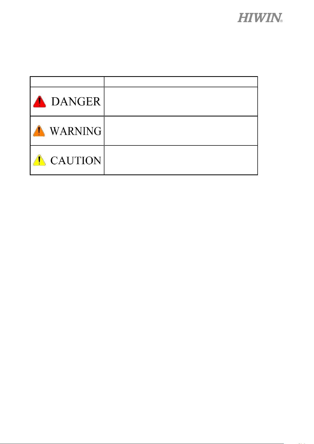
I. Safety Symbols
Carefully read the instructions in the user manual prior to robot use. The following shows
the safety symbols used in this user manual.
Symbol Description
Failure to follow instructions with this symbol may result
comply with these instructions.
Failure to follow instructions with this symbol may result
comply with these instructions.
Failure to follow instructions with this symbol may result
in poor product performance. Please be sure to comply with
these instructions.
II. Working Person
The personnel can be classified as follows
Operator:
Turns robot controller ON/OFF
Starts robot program from operator’s panel
Reset system alarm
Programmer or teaching operator:
Turns robot controller ON/OFF
Starts robot program from operator’s panel
Reset system alarm
Teaches robot
Maintenance engineer:
Turns robot controller ON/OFF
Starts robot program from operator’s panel
Reset system alarm
Teaches robot
Does maintenance, adjustment, replacement
Programmer and the maintenance engineer must be trained for proper robot operation.
5
All operating procedures should be assessed by
professional and in compliance with related
robot, operator needs to wear
safety equipment, such as workwear for working
When encountering danger or other emergency or
move the robot away with low speed in manual
A safety zone should be established around the
While installing or removing mechanical
rated load or allowable load moment at wrist.
Exceeding these values could lead to the driver
corrosion and flammable gas or close to the
Do not operate the machine at the place where
Do not immerse the electric wires into grease or
3. Precautions
3.1 Common Safety Issues
industrial safety regulations.
When operating
C01UE001-1811
environment, safety shoes and helmets.
abnormal situation, please press the emergency stop
button immediately. After danger is eliminated,
mode.
When considering safety of the robot, the robot and
the system must be considered at the same time. Be
sure to install safety fence or other safety equipment
and the operator must stand outside the safety fence
while operating the robot.
robot with an appropriate safety device to stop the
unauthorized personnel from access.
components, be aware of a falling piece which may
cause injury to operator.
Ensure the weight of workpiece does not exceed the
alarm or malfunction of the robot.
Do not climb on manipulator.
Do not store the machine in the environment with
flammable object.
Do not operate the machine in the environment with
moisture, water or grease.
vibration or the strong impact occurs.
water.
6
Do not connect or operate the machine with wet
e inner part of the
controller while it is connecting to the power or
puter inside the
hile it is operating due to its high
power is disconnected prior to repair and
ance, and ensure to operate under the
To ensure personal safety, robot installation must
comply with this manual and related industrial
fields to prevent interference that could cause the
e to avoid poor circuit
hands.
Do not operate the machine in potentially explosive
environment.
Please ensure the controller is grounded.
Keep hands away from th
during operating.
Do not touch the heat sink, regenerative resistance,
the power supply or the com
controller w
temperature.
Be sure
mainten
condition of no electrical shock risk.
C01UE001-1811
Do not disassembly the controller without
permission. If there’s any issues, please contact our
engineers.
The personnel installing robot should be trained and
licensed.
safety regulations.
The control cabinet should not be placed near high
voltage or machines that generate electromagnetic
robot to deviation or malfunction.
Using non-HIWIN spare parts to repair may cause
robot damage or malfunction.
Beware of the heat generated by the controller and
servo motor.
Do not overbend the cabl
contact or unexpected damage.
Do not stand on the controller or put heavy objects
on it.
Do not block the vent or put foreign objects into
the controller.
Please ensure the controller is fixed on the base.
7

the power of the controller when
After the brake of a servo motor is released, the
robot will be moved due to gravity and it may
special attention should be paid during the
Do not pull the connector violently or twist the
C01UE001-1811
electric wires excessively.
Do not frequently switch ON/OFF the power
switch and the control button.
Please ensure that the robot, the emergency stop
switch and the controller are functioning properly
before performing any work.
Do not shutdown the power switch during the
operation.
Do not open, modify, disassemble and maintain the
machine without permission.
The power must be disconnected when the machine
does not operate in a long time.
Do not turn off
modifying the program or parameter. Otherwise, the
data stored in the controller will be damaged.
injured the operator.
The industrial robots can be applied for the different
industrial environments.
When the operating procedures are interrupted, the
troubleshooting.
8

. Operation should be restricted at
Please contact us if the replacement of the
the service life of the robot or other
Maintenance and repair should be performed by a
mponents, avoid foreign
3.2 Operation
Teaching, jogging or programming should be done
outside of the safety fence. If it is inevitable to enter
the safety fence, press the emergency stop button
before entrance
low speed and beware of surrounding safety.
All operations shall be executed by trained staff.
3.3 Maintenance
Please contact us if the procedure not specified by
HIWIN is needed.
component not specified by HIWIN is needed.
Be sure to carry out regular maintenance, otherwise
C01UE001-1811
it will affect
unexpected danger.
Prior to repair and maintenance, please switch off
power supply.
qualified operator with a complete understanding of
the entire system to avoid risk of robot damage and
personal injury.
When replacing the co
object going into the robot.
9
effector to prevent power loss or any other errors
high voltage, high temperature and active rotary
shaft. Special attention should be paid to the
The end effector may be equipped with its own
control unit. During installation, pay attention to
type end effector should prevent the
workpiece from dropping or damaging when the
using end effector, the associated hazards must be
gripped workpiece may fall due to insufficient
The pneumatic or hydraulic system must be
equipped with the relief valve, so that it can be
C01UE001-1811
3.4 End Effector
The end effector can be classified as two types:
A. Gripper: Used to load and unload, such as pneumatic gripper, electric gripper and
vacuum sucker.
B. Tool: Used to process, such as welding, cutting and surface treatment.
More attention must be paid to the design of the end
that could lead to workpiece falling or damage.
The tool-type end effector is usually equipped with
operating safety.
The end effector should be mounted firmly on the
The gripper-
3.5 Pneumatic, Hydraulic System
robot to avoid workpiece fall during operation
which may cause personal injury or hazard.
installed location. Ensure that the control unit does
not interfere with robot operation.
robot experiences a power error or other errors. If
potential dangers or abnormal situations exist when
handled by the system integrator in accordance with
the related standards.0
When using the pneumatic or hydraulic system, the
pressure or gravity.
applied in an emergency.
10
More attention should be paid to the pressure
The internal pressure must be released before the
the atmosphere pressure.
The robot or other control component should have
The emergency stop button must be installed in an
While executing an emergency stop, power to the
Avoid using emergency stop to replace a normal
power and the control system will be
disconnected to stop all actions during the
If you want to restart the procedures, you should
Emergency stop established an immediate stop:
The emergency stop switch is used for emergency
stop switches, where one is installed on the teach
pendant and the other is directly connected to the
remained in the pneumatic systems after the power
is disconnected.
pneumatic systems are maintained.
More attention should be paid to the pressure in the
pneumatic system as it is several times more than
3.6 Emergency Stop Switch
at least one device for immediate halt, such as an
emergency stop switch.
easily accessible location for quick stop.
C01UE001-1811
servo motor will be cut, and all movements will be
stopped. And the control system will be shut down.
Emergency stop should be reset if the restoration of
operating procedure is wanted.
stop procedure. This could reduce the lifespan of the
robot.
The drive
emergency stop.
reset the emergency stop switch.
Immediately stop the robot system, and disconnect
the driver power.
stop only.
The HIWIN robot is equipped with two emergency
controller via a cable. If additional emergency stop
switches are required, other connecting method can
11

If the version of the braking is not applied to the
whole axis, once the emergency stop is executed
the axis without brake will move due to gravity.
C01UE001-1811
be applied for the same purpose.
Based on the relevant industrial safety regulations,
the emergency stop switch is directly connected to
the controller of the robot via the physical wires.
and the heavy objects are loaded on the robot end,
This attention must be paid for safety issue.
4. Intended use
HIWIN robots are industrial robots and intended for pick-and-place, handling, assembling,
deburring, grinding and polishing. Use is only permitted under the specified environment, for more
detailed information please see section 2.5 environmental conditions.
Use is not permitted under the following conditions:
Use in potentially explosive environments
Use without performing risk assessments
Transportation of people and animals
Operation outside the allowed operating parameters
5. Disposal
The disposal of HIWIN robot shall be in accordance with the local environmental regulations.
12

C01UE001-1811
Content
1. Transportation and Installation ……………………………………………….15
1.1 Transportation .................................................................................................. 15
1.2 Installation ........................................................................................................ 20
1.3 Connection with the Controller ........................................................................ 23
1.4 Grounding ........................................................................................................ 25
1.5 Environmental Conditions ............................................................................... 26
1.6 Standard and Optional Equipment List ............................................................ 27
2. Basic Specifications …………………………………………………………28
2.1 Description of Model Name ............................................................................. 28
2.2 Labels ............................................................................................................... 29
2.3 Robot Specifications ........................................................................................ 31
2.4 Outer Dimensions and Motion Range .............................................................. 33
2.5 Mechanical Stopper.......................................................................................... 35
2.6 Wrist Moment Diagram ................................................................................... 38
3. Equipment Mounting Surface and Interface ………………………………….39
3.1 Mounting Surface for End Effector ................................................................. 39
3.2 Pneumatic Interface .......................................................................................... 39
3.3 R-I/O Interface ................................................................................................. 41
4. Zero-Position …………………………………………………………………45
4.1 Zero Position Setting ........................................................................................ 45
5. Manual Brake Release Device (optional) …………………………………….50
5.1 Safety Precautions ............................................................................................ 50
5.2 Confirmation before Using .............................................................................. 51
5.3 Operation .......................................................................................................... 53
6. Maintenance and Inspection ………………………………………………….55
6.1 Maintenance and Check Interval ...................................................................... 55
6.2 Repair ............................................................................................................... 59
13

RA605、RT605 manual
6.2.1 Backup Batteries Replacement ……………………………………………...59
6.2.2 Timing Belt Replacement …………………………………………………...60
6.2.3 Grease Replenishment ………………………………………………………………………….……67
7. Safety Certification ………………………………………………………...69
8. Appendix …………………………………………………………………...70
Version Date Product Note
1.0.0 2018.03.20 RA605-710-GB First edition
C01UE001-1811
2.0.0 2018.06.30
2.1.0 2018.08.30
2.1.1 2018.10.23
RA605-GB
RT605-GB
RA605-GB
RT605-GB
RA605-GB
RT605-GB
merge
Added Chp.5 Manual
break release device,
Chp.7 Safety certification
Modified Chp.1.3 direction
of motion
14
RT605-909-GB
RA605-710-GB
RA605-710-GB
C01UE001-1811
1. Transportation and Installation
1.1 Transportation
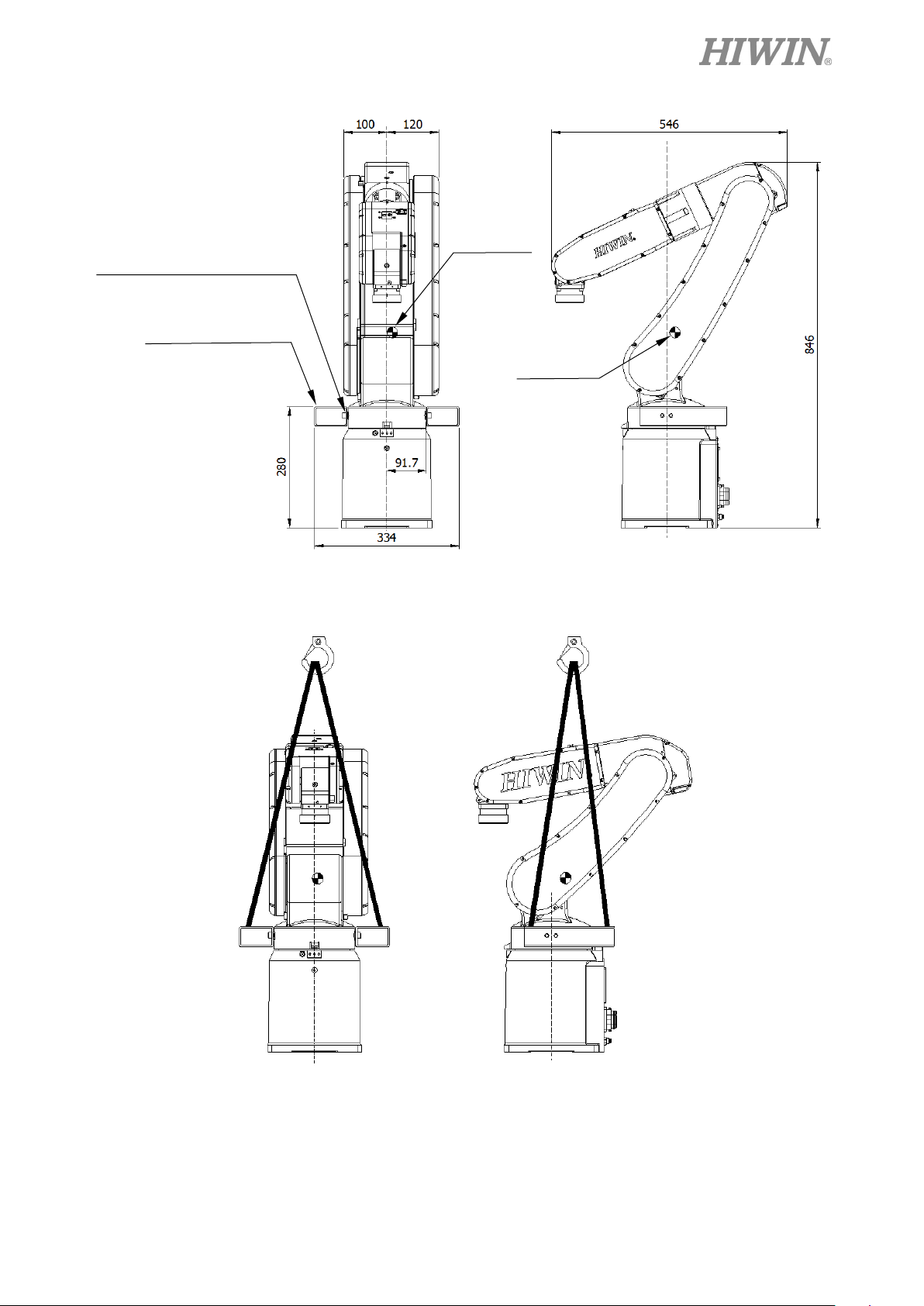
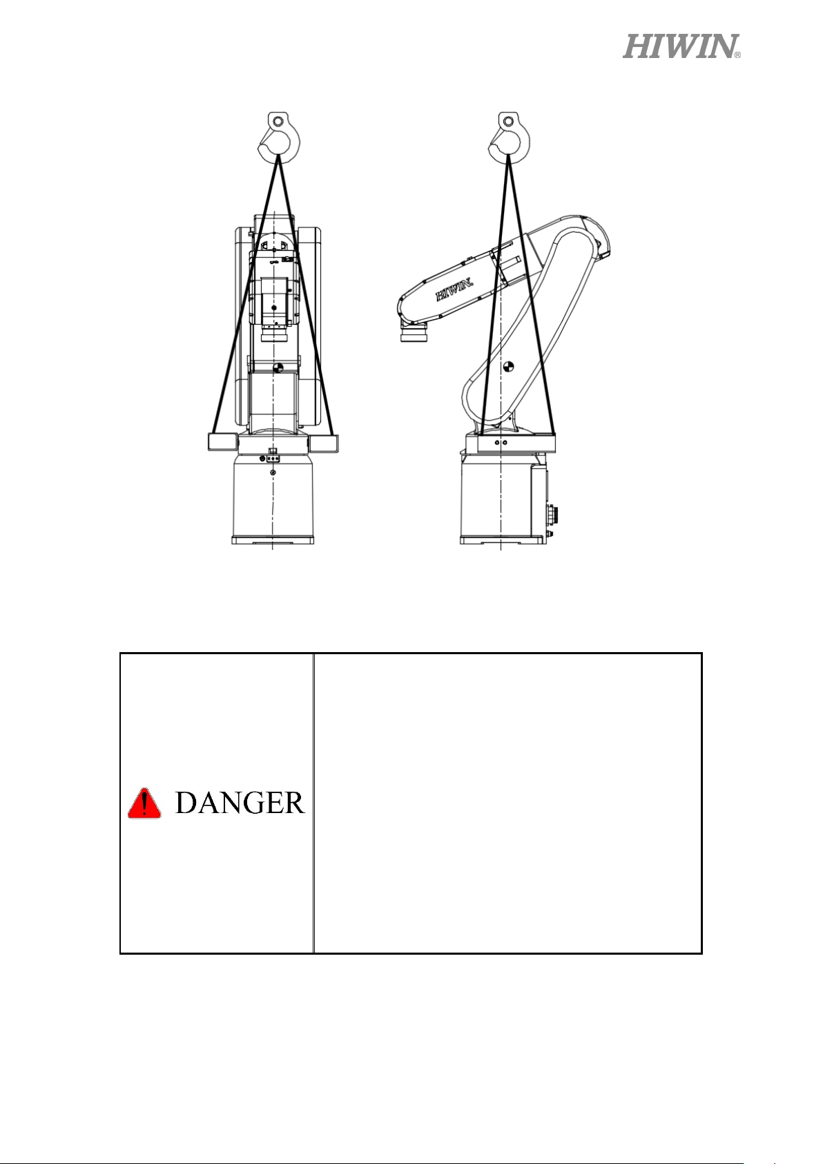
Sling can be used to transport the robot. The transportation procedure is as follows:
Step1. Move the robot into its transport posture and the angle of each joint is shown in the table
of Figure 1-1.
Step2. Secure the suspension plate to the robot with four M8×1.25P×12L screws as shown in
Figure 1-2. Make the sling go through the suspension plate to keep the center of gravity
under the hanging point shown as Figure 1-3.,Please ensure the robot is in stable
condition to avoid overturning.
Step3. Move the robot to the desired position by using sling.
Step4. Remove the suspension plate.
[Note] The transport suspension plate (4C201E41) is an optional part. Please refer to
appendix for the dimensions.
RT605-710-GB
RT605-710-GB
Figure 1-1 Transport posture
15
J4
0°
0°
Before operation, remove the suspension plate to avoid
C01UE001-1811
Transport Posture Degree
RA605-710-GB
RT605-710-GB
RT605-909-GB
J1 0° 0°
J2 45° 30°
J3 -55° -55°
J5 -80° -65°
J6 0° 0°
Before carrying the robot, be sure to remove the end
effector which changes the center of gravity.
Please keep stable, slow down and avoid excessive
vibration or shock during transportation.
While placing the robot be sure to avoid the robot and the
installation surface collision.
After removing the suspension plate, please maintain it
properly for re-transportation.
danger.
16
Gravity
Gravity
Gravity
Gravity
C01UE001-1811
Hexagon socket cap screw
M8x1.25Px12L
Suspension Plate
Figure 1-2(a) RA605-710-GB Transport dimensions
Center of
Center of
Hexagon socket cap screw
M8x1.25Px12L
Suspension Plate
Center of
Center of
Figure 1-2(b) RT605-710-GB Transport dimensions
17
Gravity
Gravity
C01UE001-1811
Hexagon socket cap screw
M8x1.25Px12L
Suspension Plate
Figure 1-2(c) RT605-909-GB Transport dimensions
Center of
Center of
Figure 1-3(a) Crane lifting transportation
RA605-710-GB Transport method
RT605-710-GB Transport method
18
Please always follow the above instructions and
Please always stay in stable condition and avoid
C01UE001-1811
Figure 1-3(b) Crane lifting transportation
RA605-909-GB Transport method
After removing the suspension plate, please keep it
properly for re-transportation.
method to transport the robot for subsequent
transportation. The angle of the suspended robot; J1
is for 0°, J2 is for 45°, J3 is for -55°, J4 is for 0°, J5
is for -80°, J6 is for 0°.
If the robot is directly suspended without using the
specified suspension plate, it will cause danger due
to an incorrect center of gravity position.
excessive vibration or shock during transportation.
19
Installation hole
Robot direction
C01UE001-1811
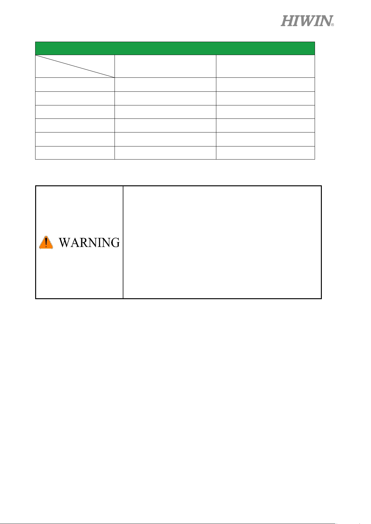
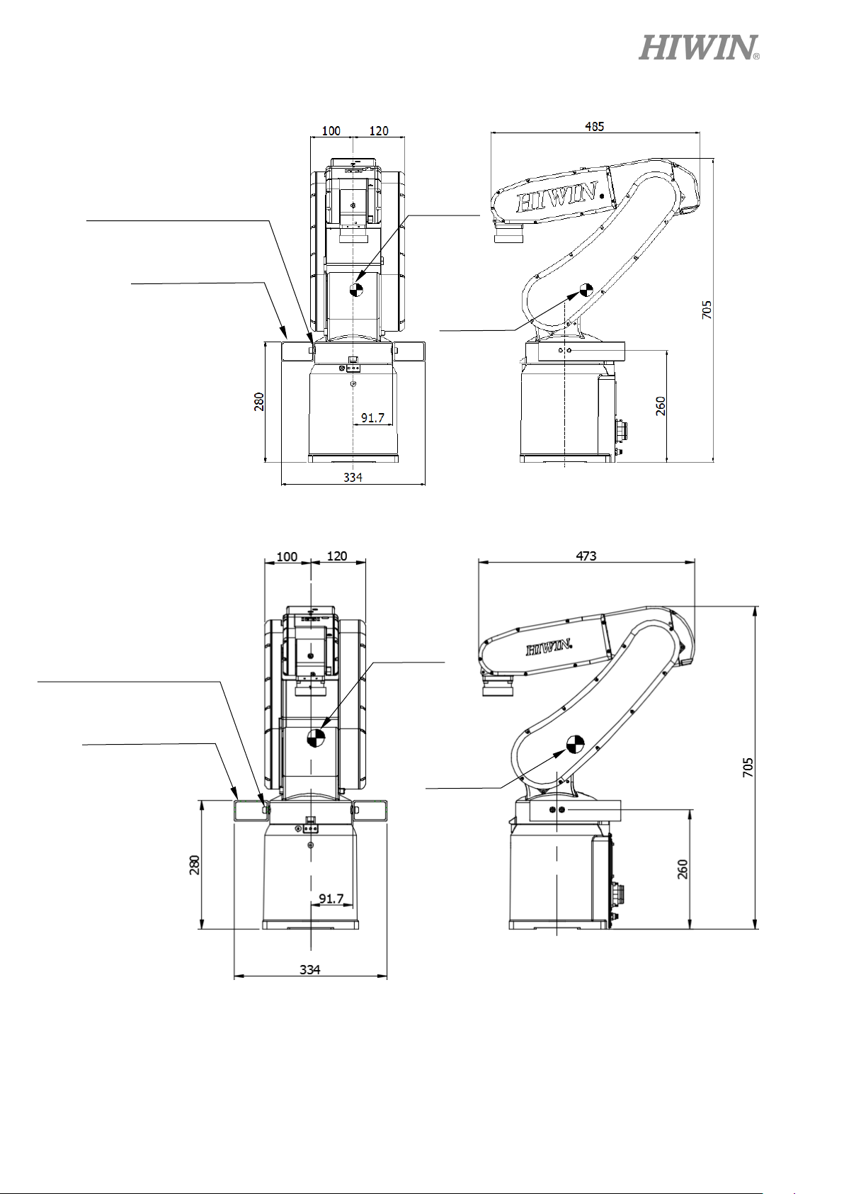
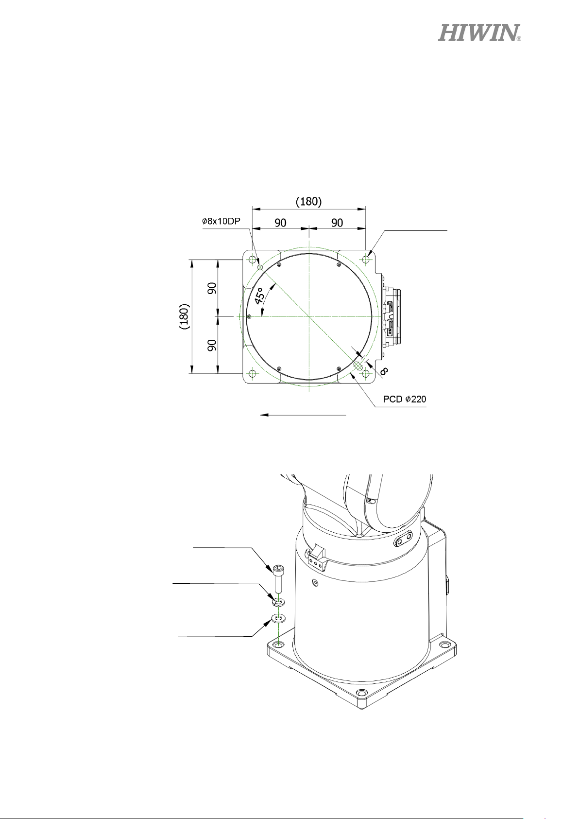
1.2 Installation
Figure 1-4 shows the installation dimensions of the robot. According to the dimensions, fix
the robot on the installation surface with M10 screws, spring washer and flat washer shown as
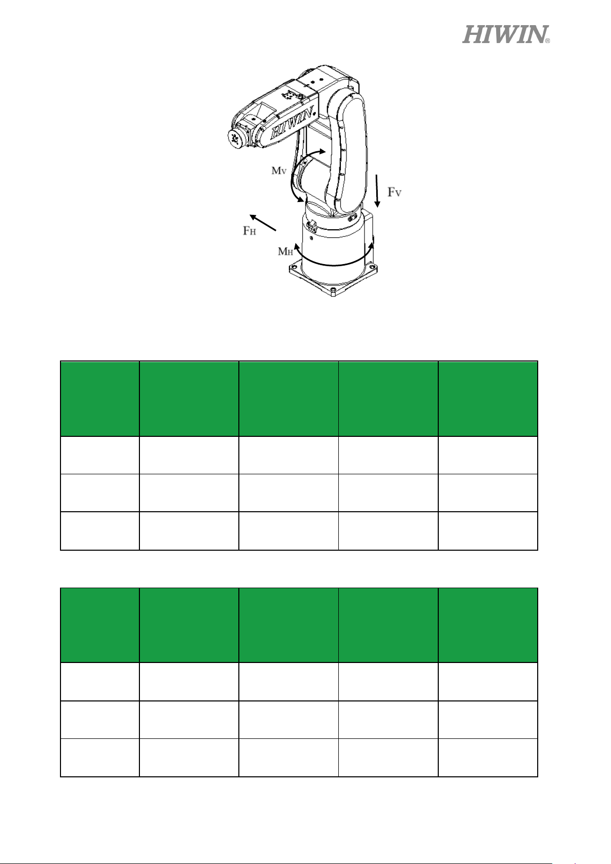
Figure 1-5. Figure 1-6 and table 1-1 show the forces and moments acting on the installation
surface during operation. The strength of surface must be considered when installing the robot.
It is recommended to use screws bigger than M10X20L.
Figure 1-4 Base dimensions
M10 screw
Spring washer
Flat washer
Figure 1-5 Installation diagram
20
C01UE001-1811
Figure 1-6 Forces and moments acting on the installation surface
Table 1-1 (RA/RT)605-710-GB Value of forces and moments acting on the installation surface
Vertical moment
Mv (Nm)
Vertical force
Fv (N)
moment
Horizontal force
MH (Nm)
Stop 144 441 0 0
Acceleration
382 1009 149 456
/Deceleration
Horizontal
Power cut stop
462 1199 248 760
Table 1-2 RT605-909-GB Value of forces and moments acting on the installation surface
Horizontal
Vertical moment
Mv (Nm)
Vertical force
Fv (N)
moment
Horizontal force
MH (Nm)
FH (N)
FH (N)
Stop 160 490 0 0
Acceleration
526 1205 244 748
/Deceleration
Power cut stop
660 1467 407 1246
21
 Loading...