

E1 Series Servo Drive
Gantry Control System
User Manual
www.hiwinmikro.tw
MD22UE01-1910_V1.0

E1 Series Servo Drive Gantry Control System User Manual Revision History
Release Date
MD22UE01-1910_V1.0
Version
Revision History
The version of the manual is also indicated on the bottom of the front cover.
Release Date Version Applicable Product Revision Contents
Oct. 15th, 2019 1.0 E1 series servo drive First edition.

E1 Series Servo Drive Gantry Control System User Manual Table of Contents
Table of Contents
1. Hardware Configuration ................................................................................................................................... 1-1
2. System Architecture ......................................................................................................................................... 2-1
2.1 Communication system architecture ................................................................................................... 2-2
2.2 Control system architecture ................................................................................................................ 2-2
2.2.1 Definition of linear/yaw axis ................................................................................................... 2-2
2.2.2 Definition of linear/yaw axis direction ..................................................................................... 2-3
3. Setting Procedure ............................................................................................................................................ 3-1
3.1 Single axis setting ............................................................................................................................... 3-2
3.2 Establish communication system ........................................................................................................ 3-2
3.3 Confirmation before activating gantry control system ......................................................................... 3-4
3.4 Activate gantry control system ............................................................................................................ 3-4
3.5 Homing procedure............................................................................................................................... 3-5
4. Gain Tuning ...................................................................................................................................................... 4-1
4.1 Single axis gain tuning ........................................................................................................................ 4-2
4.2 Gantry control gain tuning ................................................................................................................... 4-2
4.3 Current ratio parameter ....................................................................................................................... 4-3
4.4 Velocity ripple compensation .............................................................................................................. 4-3
5. Safety Protection Function ............................................................................................................................... 5-1
5.1 Enable/Disable axes in gantry control system .................................................................................... 5-2
5.2 Motor stopping method for alarm ........................................................................................................ 5-2
5.3 Relevant alarms .................................................................................................................................. 5-2
6. Advanced Setting ............................................................................................................................................. 6-1
6.1 Error map ............................................................................................................................................ 6-2
7. Gantry Control Interface Setting ...................................................................................................................... 7-1
E1 Series Servo Drive Gantry Control System User Manual Preface
Preface
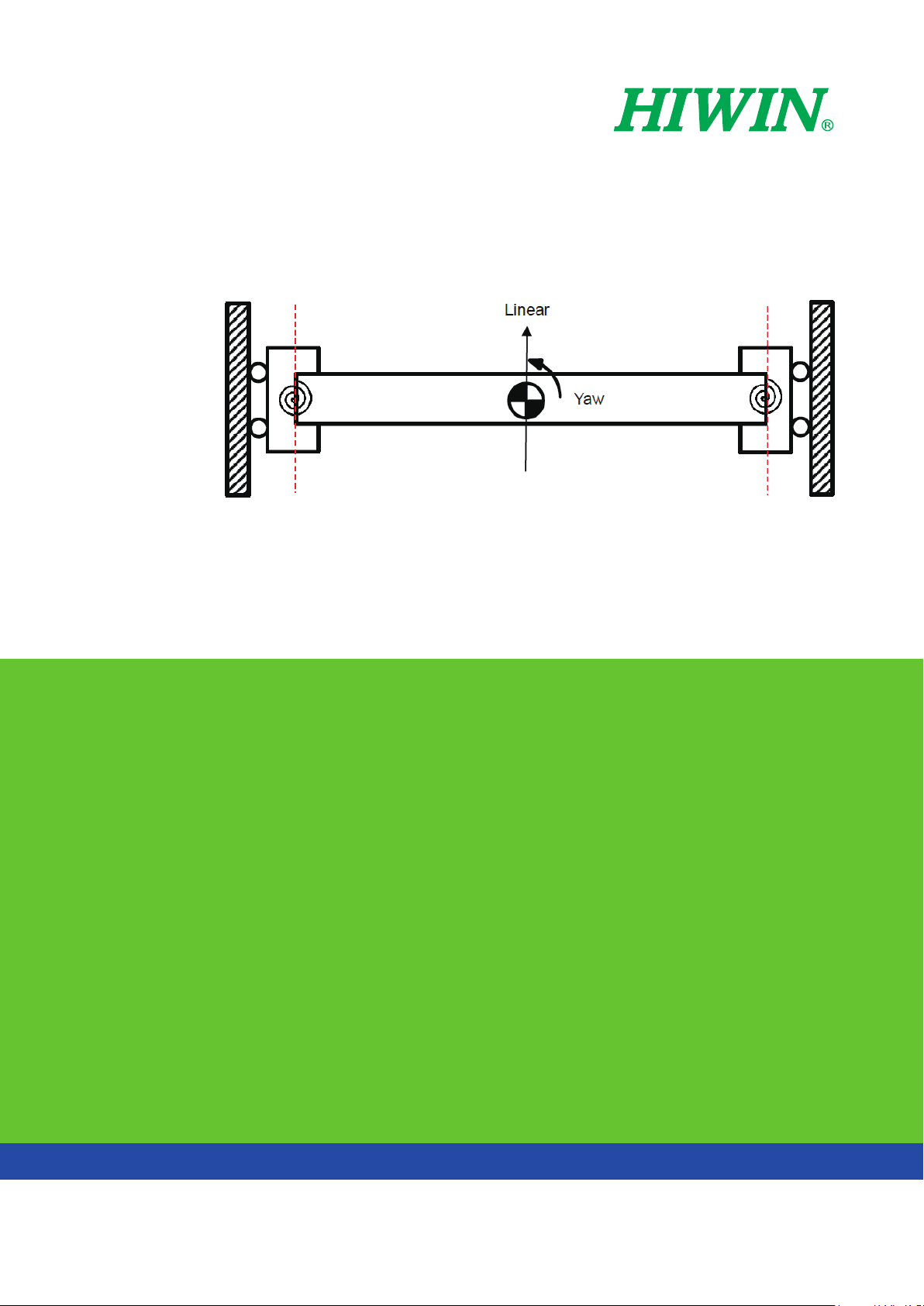
Gantry control system: high-performance response gantry control can be achieved by high-speed data
exchange technology between two servo drives. Please select ED1□-□G model.
Linear
Yaw

1. Hardware Configuration
1. Hardware Configuration ................................................................................................................................... 1-1
E1 Series Servo Drive Gantry Control System User Manual Hardware Configuration
MD22UE01-1910
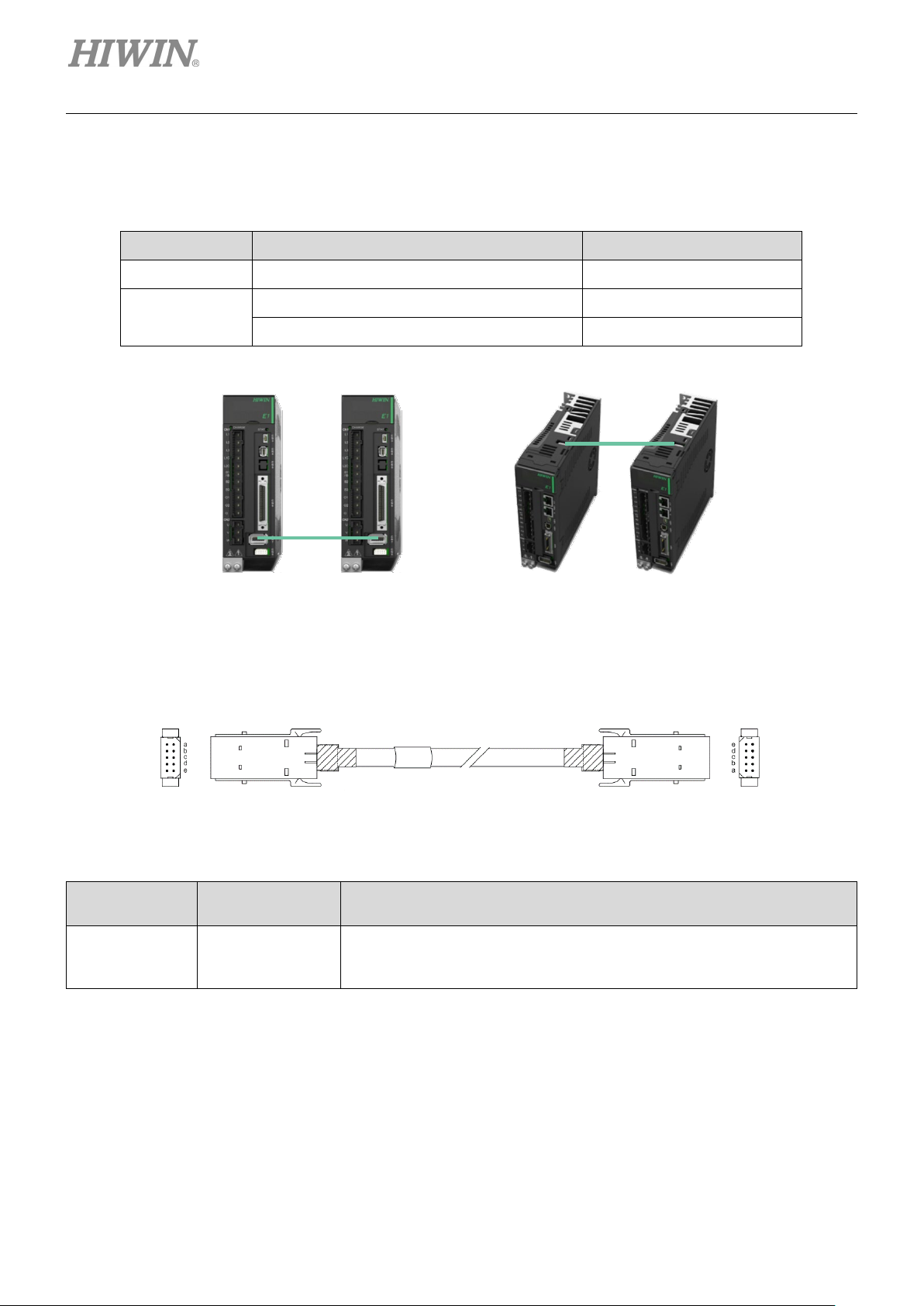
Standard
Fieldbus
Select the model supporting gantry function and connect two servo drives via CN8 with the communication
cable.
Table 1.1
Type Control Interface Model
Standard Voltage command and pulse ED1S-VG-□□□□-□□
Fieldbus
mega-ulink (For HIMC motion controller) ED1S-HG-□□□□-□□
EtherCAT ED1S-EG-□□□□-□□
Figure 1.1 CN8 position
Servo drive 1 CN8
Servo drive 2 CN8
Figure 1.2 Servo drive communication cable (for gantry control system)
Table 1.2 Communication cable for gantry function
Name
Servo drive
communication
cable
HIWIN Part
Number
HE00EJ6DD000
Description
Connect two servo drives which both support gantry function via CN8.
(0.5 m)
1-2 HIWIN MIKROSYSTEM CORP.

2. System Architecture
2. System Architecture ......................................................................................................................................... 2-1
2.1 Communication system architecture ................................................................................................... 2-2
2.2 Control system architecture ................................................................................................................ 2-2
2.2.1 Definition of linear/yaw axis ................................................................................................... 2-2
2.2.2 Definition of linear/yaw axis direction ..................................................................................... 2-3
E1 Series Servo Drive Gantry Control System User Manual System Architecture
MD22UE01-1910
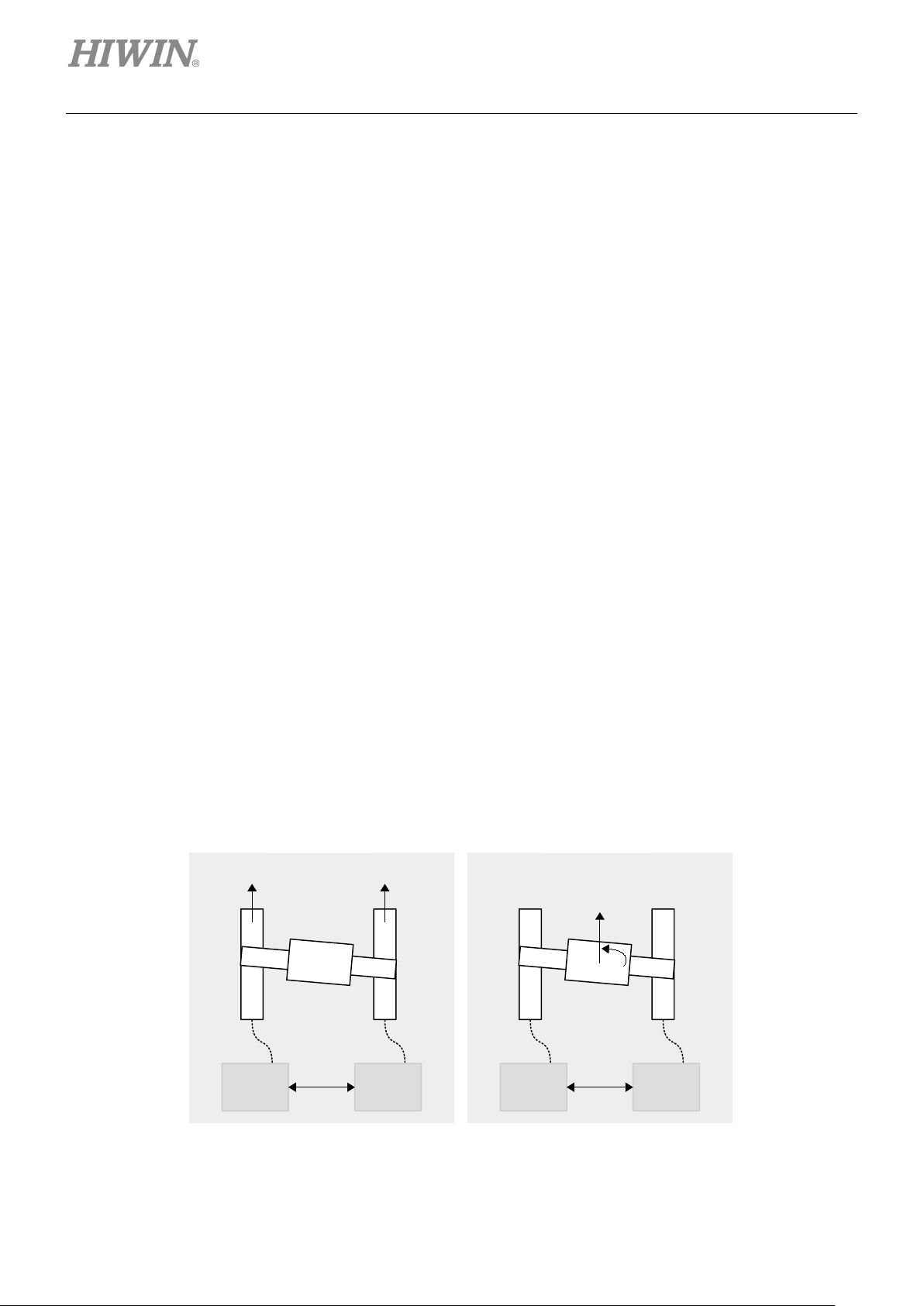
drive 0
(Master)
drive 1
(Slave)
axis 0
axis 1
drive 0
(Linear)
drive 1
(Ya w)
linear
yaw
Single axis mode
Gantry mode
To build a complete gantry control system, two servo drives, two motors and the corresponding encoders
must be prepared as two axes. Before activating gantry control system through setting, establish
communication system between two servo drives first.
2.1 Communication system architecture
Connect CN8 via the cable (refer to “E1 Series Servo Drive User Manual”) and establish communication
system (refer to section 3.2). In communication system, the relationship of master and slave exists in the
two servo drives.
2.2 Control system architecture
2.2.1 Definition of linear/yaw axis
After establishing communication system, users can enter gantry control system via gantry control
interface (refer to chapter 7). After entering gantry control system, two axes’ linear (axis 0 and axis 1)
coordinate system will respectively become linear coordinate system and yaw coordinate system. The
relationship between “Master/Slave” and “Linear/Yaw” is described as below.
Master axis → Linear axis
Slave axis → Yaw axis
2-2 HIWIN MIKROSYSTEM CORP.
Figure 2.2.1.1

E1 Series Servo Drive Gantry Control System User Manual System Architecture
MD22UE01-1910
Example 1
Master Slave
yaw
linear
Example 2
Slave
Master
yaw
linear
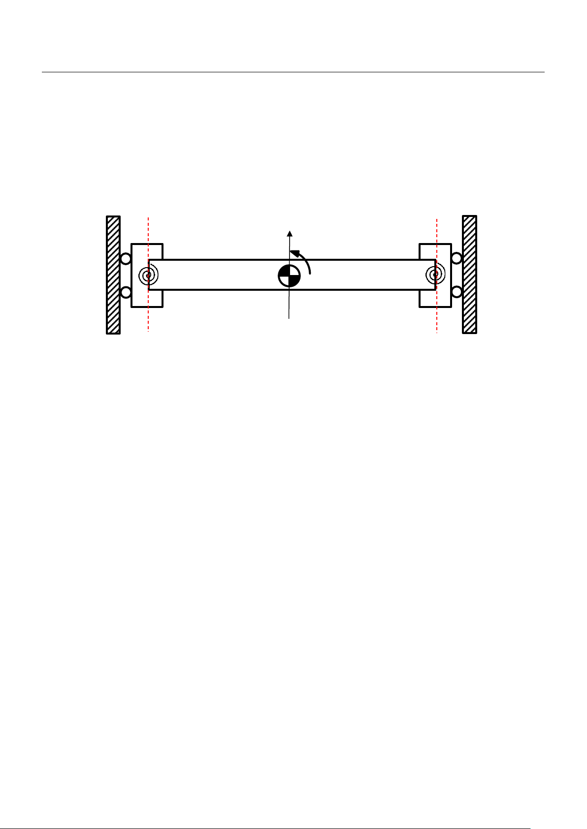
2.2.2 Definition of linear/yaw axis direction
Definition of linear axis direction
The linear positive direction of single axis moving part is the positive direction of linear axis.
Definition of yaw axis direction
If the positive direction of linear axis and the position of master are already known, the positive
direction of yaw axis can be determined by gantry right-hand rule, as the following figure shows.
Figure 2.2.2.1
HIWIN MIKROSYSTEM CORP. 2-3

E1 Series Servo Drive Gantry Control System User Manual System Architecture
MD22UE01-1910
(This page is intentionally left blank.)
2-4 HIWIN MIKROSYSTEM CORP.

3. Setting Procedure
3. Setting Procedure ............................................................................................................................................ 3-1
3.1 Single axis setting ............................................................................................................................... 3-2
3.2 Establish communication system ........................................................................................................ 3-2
3.3 Confirmation before activating gantry control system ......................................................................... 3-4
3.4 Activate gantry control system ............................................................................................................ 3-4
3.5 Homing procedure............................................................................................................................... 3-5

E1 Series Servo Drive Gantry Control System User Manual Setting Procedure
MD22UE01-1910
To make gantry control system operate normally, some features of the two axes must be the same. Before
setting, ensure hardware and software configuration fits the following requirements, or it may cause danger
to the stage.
Same servo drive model
Same firmware version
Same positive moving direction (Check it when finishing single axis setting in section 3.1.)
Same encoder feedback pulse resolution (Besides hardware specification, check point III in section
3.3.)
Note: Single axis may be driven in the setting process; therefore, ensure the other axis remains freely-operating
status, not influenced by the brake.
3.1 Single axis setting
Gantry mode must drive the servo drives and the motors of both axes. Therefore, respectively execute
single-axis initialization based on “E1 Series Servo Drive Thunder Software Operation Manual”. The
setting procedure is shown as below.
I. Connect to master servo drive and execute single-axis initialization.
II. Set and record the positive moving direction of master motor.
III. Connect to slave servo drive and execute single-axis initialization.
IV. Set and record the positive moving direction of slave motor, which should be the same as that of
master motor.
3.2 Establish communication system
All the functions of gantry mode are based on the establishment of communication system. Therefore,
communication system must be established first. The setting procedure is shown as below.
3-2 HIWIN MIKROSYSTEM CORP.

E1 Series Servo Drive Gantry Control System User Manual Setting Procedure
MD22UE01-1910
drive 0
(Master)
drive 1
(Slave)
axis 0
axis 1
I. Build up the relationship of master and slave.
A. Connect to the left servo drive in figure 3.2.1 and set Pt00D = 0x1 (define it as master).
B. Reboot the left servo drive to make it become effective.
C. Connect to the right servo drive in figure 3.2.1 and set Pt00D = 0x0 (define it as slave).
D. Reboot the right servo drive to make it become effective.
Figure 3.2.1
II. Open Interface signal monitor window in Thunder main window to ensure master axis’
communication is established, as the red frame in figure 3.2.2 shows.
Figure 3.2.2
Note: When communication system is established, alarm AL.FC0 or AL.FC1 may be triggered if users power off any
of the axes. Refer to section 5.5 for cause, confirmation method and corrective action.
HIWIN MIKROSYSTEM CORP. 3-3

E1 Series Servo Drive Gantry Control System User Manual Setting Procedure
MD22UE01-1910
3.3 Confirmation before activating gantry control system
Before activating gantry control system, double check some parameters and the resolution. The setting
procedure is shown as below.
I. Ensure some Pt parameters of both axes are the same.
A. Connect to master servo drive and record Pt001, Pt20E, Pt210, Pt428, Pt402/Pt483,
Pt403/Pt484.
B. Connect to slave servo drive and ensure the values of the parameters above are the same as
those in master axis.
II. Connect to master servo drive to ensure communication is established.
III. Ensure the encoder resolutions of both axes are the same.
A. Connect to master servo drive.
B. Make the motor move at least one magnetic pole pair pitch with test run.
C. Monitor the encoder feedback of both axes via Scope. (Observe position feedback of master
axis and slave axis.)
D. Ensure the incremental direction and the ratio of encoder feedback values are the same.
IV. When this section is completed, the two servo drives can enter gantry mode via gantry control
interface.
3.4 Activate gantry control system
There are two ways to activate gantry control system, manual or auto. Manual is for Thunder HMI test run,
while auto is for host controller. The setting method is shown as below.
Manual
Go to gantry control interface and click Activate button (refer to step 4 in chapter 7).
Auto
Set Pt00D = 1 in master servo drive to activate auto gantry function.
Note:
1. Before entering gantry mode, ensure things in section 3.1 to 3.3 are completed.
2. After entering gantry mode, both axes are viewed as single linear system. Therefore, master axis test run
represents linear axis test run.
3. If auto gantry function is activated, users cannot deactivate gantry mode via gantry control interface.
3-4 HIWIN MIKROSYSTEM CORP.

E1 Series Servo Drive Gantry Control System User Manual Setting Procedure
MD22UE01-1910
3.5 Homing procedure
After entering gantry mode, both axes are viewed as single linear system. Therefore, homing methods
applied in single axis control system (refer to “E1 Series Servo Drive User Manual” for the description) are
applicable for gantry control system. The setting procedure is shown as below.
Linear axis homing
I. Ensure both axes have entered gantry mode.
II. Connect to linear servo drive via Thunder HMI or host controller.
III. Set homing method.
IV. Enable the motors. Execute homing via Thunder HMI, or trigger servo drive built-in homing procedure
input (HOM) signal via host controller.
V. Wait until homing is completed.
At this time, users only complete linear axis homing procedure. Go on to complete posture regulating
setting procedure.
Posture regulating setting
VI. Disable the motors at home position.
VII. (Optional) Record the posture position of yaw axis, add a negative sign to the value, and fill it in Pt711
- Home offset of yaw axis in gantry control system. At this time, the posture position of yaw axis will
be close to 0.
VIII. Record the posture position of yaw axis again, and set the record value to Pt712 - Locking position
of yaw axis in gantry control system. (If step VII is done, users can directly set Pt712 as 0.)
IX. Set Pt710 = 0x1 to activate yaw lock function.
X. Enable the motors. Yaw axis will be locked at the position set by Pt712.
When yaw lock function is activated and the parameters are saved to servo drives, users can complete
homing procedure of linear/yaw axis via Thunder HMI or host controller even if the stage is rebooted.
Note:
1. Definition of linear axis home position: the center of two axes’ Z-phase reference points
2. Definition of yaw axis home position:
the posture that the two axes’ Z-phase reference points take as supporting point
Before Pt711 is set, a deviation must exist in the installation of two axes’ Z-phase reference points. Therefore,
it is reasonable that there is a nonzero value in yaw axis after homing is completed.
HIWIN MIKROSYSTEM CORP. 3-5

E1 Series Servo Drive Gantry Control System User Manual Setting Procedure
MD22UE01-1910
3. Overtravel (P-OT or N-OT) signal received by master and slave servo drive can only be triggered in linear servo
drive. Therefore, triggering any axis’ overtravel signal satisfies the triggering overtravel signal procedure of
homing.
4. Near home sensor input (DOG) signal only supports master servo drive. Therefore, only triggering master axis’
near home sensor input signal satisfies the triggering near home sensor input signal procedure of homing.
5. In gantry control system, before yaw lock function is activated, the posture of yaw axis when the motors are
enabled will be taken as the reference position to make the mechanism be at a comfortable state. Therefore,
the posture of yaw axis will not be arbitrarily changed.
3-6 HIWIN MIKROSYSTEM CORP.

4. Gain Tuning
4. Gain Tuning ...................................................................................................................................................... 4-1
4.1 Single axis gain tuning ........................................................................................................................ 4-2
4.2 Gantry control gain tuning ................................................................................................................... 4-2
4.3 Current ratio parameter ....................................................................................................................... 4-3
4.4 Velocity ripple compensation .............................................................................................................. 4-3

E1 Series Servo Drive Gantry Control System User Manual Gain Tuning
MD22UE01-1910
4.1 Single axis gain tuning
When to use: Before entering gantry mode, users want to move the motor by driving single axis.
In this case, the target is to make it stable. Refer to “E1 Series Servo Drive User Manual” for the setting
method.
4.2 Gantry control gain tuning
When to use: After entering gantry mode. Pay attention to the following reminders before tuning.
1. The appropriate gains for gantry control system are different from those for single axis control system.
To avoid the inconvenience of switching, in single axis control system, velocity loop gain, velocity loop
integral time constant, position loop gain and moment of inertia ratio are respectively Pt100, Pt101,
Pt102 and Pt103. In gantry control system, they are changed to Pt190, Pt191, Pt192 and Pt193. The
two systems share gain parameters (Pt1) and torque filter parameters (Pt4).
2. The servo drive’s control system is no longer single axis control. Instead, it turns into linear coordinate
system and yaw coordinate system of gantry mode.
3. The position information displayed by master axis is no longer encoder position feedback of single
axis; it becomes position feedback of linear coordinate system, the average value of two axes’ position
feedback. The position information displayed by slave axis becomes position feedback of yaw
coordinate system, the deviation of two axes’ position feedback.
4. Giving commands to master axis represents giving commands to linear axis direction of both axes.
Besides, users can give commands to yaw axis via master axis window in gantry control interface if
yaw lock function is not activated.
5. Gain parameters and protection parameters in master axis correspond to linear coordinate system;
gain parameters and protection parameters in slave axis correspond to yaw coordinate system.
6. In gantry control system, tuneless function is still available. Before operating manual gain tuning,
remember to close the function.
7. In gantry control system, auto tuning is still available.
8. In gantry control system, linear axis’ moment of inertia ratio is approximately equal to that of single
axis, while yaw axis’ moment of inertia ratio is approximately equal to 1/3 times that of single axis.
9. Gantry control system only supports frequency analyzer for closed loop control. To avoid the
resonance caused by poor initial gain, fill Pt103 - single axis’ moment of inertia ratio in Pt193
according to the above ratio before measuring.
4-2 HIWIN MIKROSYSTEM CORP.

E1 Series Servo Drive Gantry Control System User Manual Gain Tuning
MD22UE01-1910
4.3 Current ratio parameter
In gantry control system, a connection relationship exists in the structure of the two axes. Excessive force
from yaw axis may cause damage to the stage. To ensure yaw axis’ force limit, users can set linear axis’
and yaw axis’ distribution ratio of current limit via Pt428.
For example, without considering force limit, if servo drive’s peak limit is 10 A and the Pt428 parameter
value is set as 80, linear axis’ current limit will be set as 8 A, and yaw axis’ current limit will be set as 2 A.
In general, the stronger the stiffness, the bigger the Pt428 parameter value should be set.
Note: In gantry control system, distribution ratio of current limit must be synchronously modified in both axes.
Therefore, when users modify the Pt428 parameter value of one axis, do not forget to synchronously modify that of
the other axis.
4.4 Velocity ripple compensation
In gantry control system, servo drive does not support velocity ripple compensation.
HIWIN MIKROSYSTEM CORP. 4-3

E1 Series Servo Drive Gantry Control System User Manual Gain Tuning
MD22UE01-1910
(This page is intentionally left blank.)
4-4 HIWIN MIKROSYSTEM CORP.

5. Safety Protection Function
5. Safety Protection Function ............................................................................................................................... 5-1
5.1 Enable/Disable axes in gantry control system .................................................................................... 5-2
5.2 Motor stopping method for alarm ........................................................................................................ 5-2
5.3 Relevant alarms .................................................................................................................................. 5-2

E1 Series Servo Drive Gantry Control System User Manual Safety Protection Function
MD22UE01-1910
could be disconnection of the
communication cable or poor
Check if the communication
Check if the communication
Check if there is interference
source or the communication
Add ferrite ring or replace the
eset one of the
Perform alarm reset on master
via Thunder or external
Communication cannot be
Check if the communication
Check if the communication
Incorrectly operating gantry control system may cause damage to the stage. For safety, pay attention to
the following features before entering gantry mode.
5.1 Enable/Disable axes in gantry control system
1. After entering gantry mode, both axes are viewed as single linear system, and master axis is in the
position of control. Therefore, enabling master axis equals enabling both axes; disabling master axis
equals disabling both axes.
2. When gantry control system is activated, both axes will be disabled if any axis triggers an error.
5.2 Motor stopping method for alarm
In gantry control system, the setting of Pt00A = 0x1 in slave servo drive will be ignored; only Pt001
= 0x1 will be used.
5.3 Relevant alarms
AL.FC0 Gantry control system communication error
Table 4.3.1
Cause Confirmation Method Corrective Action
Communication is interrupted. It
cable is correctly connected.
connection.
Communication is interfered.
cable is not correctly connected.
Power off or r
axes.
N/A
cable is correctly connected.
communication cable.
axis
signal, or reset both axes.
established (only detected when
auto gantry is activated).
Note:
1. After the relationship of master and slave is built up, users should power off and reset the servo drives to make
some Pt parameters become effective. Therefore, it is normal if alarm AL.FC0 occurs.
5-2 HIWIN MIKROSYSTEM CORP.
cable is correctly connected.
cable is correctly connected.

E1 Series Servo Drive Gantry Control System User Manual Safety Protection Function
MD22UE01-1910
After the cause of the error is
via Thunder or
reset both
2. In gantry control interface, clearing the error or entering alarm reset input (ALM-RST) signal in master axis
window represents clearing the error of both axes.
AL.FC1 Slave axis error in gantry control system
Table 4.3.2
Cause Confirmation Method Corrective Action
An error occurs in the slave axis
of gantry control system.
Note:
1. If any error occurs in slave axis, alarm AL.FC1 will pop up in master axis window to inform users and host
controller.
Check the cause of the error.
cleared, perform alarm reset on
master axis
external signal, or
axes.
2. In gantry control interface, clearing the error or entering alarm reset input (ALM-RST) signal in master axis
window represents clearing the error of both axes.
HIWIN MIKROSYSTEM CORP. 5-3

E1 Series Servo Drive Gantry Control System User Manual Safety Protection Function
MD22UE01-1910
(This page is intentionally left blank.)
5-4 HIWIN MIKROSYSTEM CORP.

6. Advanced Setting
6. Advanced Setting ............................................................................................................................................. 6-1
6.1 Error map ............................................................................................................................................ 6-2

E1 Series Servo Drive Gantry Control System User Manual Advanced Setting
MD22UE01-1910
6.1 Error map
Linear axis
The usage is similar to that of single axis. The sources are from linear axis’ original positions, and the
position of linear axis will be compensated. The setting procedure is shown as below.
I. Set up linear axis’ error map and save it to master servo drive (refer to “E1 Series Servo Drive
Thunder Software Operation Manual”).
II. Set Pt009 = 0x
III. Activate gantry control system.
IV. Execute homing procedure.
V. Check “Activate error map” to make it become effective.
Yaw axis
The sources are also from linear axis’ original positions, but the position of yaw axis will be
compensated. The setting procedure is shown as below.
I. Set up yaw axis’ error map and save it to slave servo drive (refer to “E1 Series Servo Drive
Thunder Software Operation Manual”).
II. Set Pt009 = 0x
III. Check “Activate error map”.
IV. Connect to master servo drive and activate gantry control system.
V. Execute homing procedure.
VI. After homing is completed, it becomes effective.
1 in master servo drive.
1 in slave servo drive.
6-2 HIWIN MIKROSYSTEM CORP.

7. Gantry Control Interface Setting
7. Gantry Control Interface Setting ...................................................................................................................... 7-1

E1 Series Servo Drive Gantry Control System User Manual Gantry Control Interface Setting
MD22UE01-1910
Here takes linear motor as an example to show the setting of gantry control interface.
Step 1. Presetting of gantry control (refer to section 3.1 to 3.3)
Step 2. Open Gantry control system window
(1) Select Gantry control system in Tools.
(2) Ensure the status light of Group communication lights up in green (which means the
communication between Master and Slave is fine).
Note: When the setting of Master and Slave is done, operate Master to start gantry control.
Figure 7.1 Open Gantry control system window
Step 3. Respectively enable Master and Slave
(1) Click Enable button of Master. When the motor is enabled, the status light of Enable in
Master will light up in green, as figure 7.2 shows. Click Disable button of Master.
(2) Click Enable button of Slave. When the motor is enabled, the status light of Enable in
Slave will light up in green, as figure 7.3 shows. Click Disable button of Slave.
Figure 7.2 Enable Master Figure 7.3 Enable Slave
7-2 HIWIN MIKROSYSTEM CORP.

E1 Series Servo Drive Gantry Control System User Manual Gantry Control Interface Setting
MD22UE01-1910
Step 4. Start gantry control
(1) Click Activate button, and wait for the status light of Gantry mode to light up in green.
(2) When it succeeds, the label of Master and Slave will become Linear and Yaw.
Figure 7.4 Start gantry control
Step 5. Enable axes on gantry mode
(1) Click Enable button of Linear. At this time, both axes are enabled, and both the status
lights of Enable in Linear and Yaw light up in green.
(2) After ensuring the axes can be normally enabled, click Disable button of Linear to
disable the motors.
Figure 7.5 Enable status on gantry mode
HIWIN MIKROSYSTEM CORP. 7-3

E1 Series Servo Drive Gantry Control System User Manual Gantry Control Interface Setting
MD22UE01-1910
Step 6. Test run on gantry mode
Close Gantry control system window. Click to open Test Run window and observe
the synchronous effect on gantry mode with low velocity jog (e.g., 50 mm/s).
Figure 7.6 Low velocity jog on gantry mode
Step 7. Observe the position of linear axis / yaw axis / single axis
Click to open Real-time Scope window and select the items to be monitored. The
relevant physical quantities for gantry control system include “2 - Feedback position”, “19 -
Yaw position”, “17 - Master feedback position” and “18 - Slave feedback position”.
7-4 HIWIN MIKROSYSTEM CORP.
Figure 7.7 Monitor the relevant physical quantities for gantry control system via Real-time Scope
 Loading...