

Hiwin E1 Command Manual

E1 Series Servo Drive
EtherCAT(CoE) Communications
Command Manual
www.hiwinmikro.tw

E1 Series Servo Drive EtherCAT(CoE) Communications Command Manual Revision History
Revision History
Release Date Version Applicable Product Revision Contents
Dec. 04th, 2018 1.0 E1-series CoE drive First edition.

E1 Series Servo Drive EtherCAT(CoE) Communications Command Manual Table of Contents
Table of Contents
1. About this Manual ............................................................................................................................................ 1-1
1.1 Preface............................................................................................................................................ 1-2
1.2 Trademark ....................................................................................................................................... 1-2
1.3 General precautions ....................................................................................................................... 1-3
1.4 Safety precautions .......................................................................................................................... 1-4
2. EtherCAT Communication ................................................................................................................................ 2-1
2.1 System configuration ...................................................................................................................... 2-2
2.2 Specifications .................................................................................................................................. 2-2
2.3 EtherCAT frame structure ............................................................................................................... 2-4
2.3.1 EtherCAT commands ............................................................................................................. 2-5
2.3.2 WKC (Working Counter) ........................................................................................................ 2-6
2.4 EtherCAT State Machine ................................................................................................................ 2-7
2.5 Synchronous mode ....................................................................................................................... 2-10
2.5.1 DC ........................................................................................................................................ 2-10
2.5.2 FreeRun ................................................................................................................................ 2-11
2.6 SDO abort code ............................................................................................................................. 2-11
2.7 Emergency message .................................................................................................................... 2-12
2.8 PDO (Process Data Object) ......................................................................................................... 2-13
2.8.1 PDO mapping object ............................................................................................................ 2-13
2.8.2 PDO assign object ............................................................................................................... 2-14
2.9 EtherCAT display and setting area ............................................................................................... 2-15
2.9.1 Node address setting ........................................................................................................... 2-15
2.9.2 EtherCAT indicators ............................................................................................................. 2-16
2.10 EtherCAT related errors ................................................................................................................ 2-17
3. Object Dictionary .............................................................................................................................................. 3-1
3.1 Communication profile area ............................................................................................................ 3-2
3.1.1 Default PDO mapping ............................................................................................................ 3-7
3.1.2 Mapping objects to PDO ........................................................................................................ 3-9
3.1.3 PDO data exchange timing ................................................................................................... 3-11
3.2 Standardized device profile area .................................................................................................. 3-12
3.2.1 PDS (Power Drive System) .................................................................................................. 3-19
3.2.2 Profile position mode (pp) .................................................................................................... 3-22

E1 Series Servo Drive EtherCAT(CoE) Communications Command Manual Table of Contents
Table of Contents
3.2.3 Cyclic synchronous position mode (csp) ............................................................................. 3-29
3.2.4 Homing mode (hm) .............................................................................................................. 3-31
3.2.5 Profile velocity mode (pv) ..................................................................................................... 3-36
3.2.6 Cyclic synchronous velocity mode (csv) .............................................................................. 3-37
3.2.7 Profile torque mode (tq) ....................................................................................................... 3-39
3.2.8 Cyclic synchronous torque mode (cst) ................................................................................. 3-41
3.2.9 Touch probe function ............................................................................................................ 3-42
3.3 Manufacturer specific profile area ................................................................................................ 3-45
3.3.1 Absolute encoder initialization ............................................................................................. 3-45
3.4 Object dictionary list ...................................................................................................................... 3-46

1. About this Manual
1. About this Manual ............................................................................................................................................ 1-1
1.1 Preface............................................................................................................................................ 1-2
1.2 Trademark ....................................................................................................................................... 1-2
1.3 General precautions ....................................................................................................................... 1-3
1.4 Safety precautions .......................................................................................................................... 1-4

E1 Series Servo Drive EtherCAT(CoE) Communications Command Manual About this Manual
MD08UE01-1812
1.1 Preface
This manual introduces EtherCAT (Ethernet for Control Automation Technology) communication and CiA
402 drive profile applied to E1-series CoE (CANopen over EtherCAT) drive. As for basic specifications,
wiring and settings of E1-series drive, please refer to “E1 Series Servo Drive User Manual”.
1.2 Trademark
EtherCAT ® is a registered trademark and a patent technology, licensed by Beckhoff Automation GmbH,
Germany.
1-2 HIWIN MIKROSYSTEM Corp.

E1 Series Servo Drive EtherCAT(CoE) Communications Command Manual About this Manual
MD08UE01-1812
1.3 General precautions
This manual is for E1-series CoE drive. Before using the product, please carefully read through this manual.
HIWIN Mikrosystem (HIWIN) is not responsible for any damage, accident or injury caused by failure in
following the installation instructions and operating instructions stated in this manual.
Do not disassemble or modify the product. The design of the product has been verified by structural
calculation, computer simulation and actual testing. HIWIN is not responsible for any damage,
accident or injury caused by disassembly or modification done by users.
Before installing or using the product, ensure there is no damage on its appearance. If any damage
is found after inspection, please contact HIWIN or local distributors.
Carefully read through the specification noted on product label or technical document. Install the
product according to its specification and installation instructions stated in this manual.
Ensure the product is used with power supply specified on product label or in product requirement.
HIWIN is not responsible for any damage, accident or injury caused by incorrect power supply.
Ensure the product is used with rated load. HIWIN is not responsible for any damage, accident or
injury caused by improper usage.
Do not subject the product to shock. HIWIN is not responsible for any damage, accident or injury
caused by improper usage.
If an error occurs in the drive, please refer to “E1 Series Servo Drive User Manual” and follow the
instructions for troubleshooting. After the error is eliminated, power on the drive again.
Do not repair the product by yourself when it malfunctions. The product can only be repaired by
qualified technician from HIWIN.
HIWIN MIKROSYSTEM Corp. 1-3
E1 Series Servo Drive EtherCAT(CoE) Communications Command Manual About this Manual
MD08UE01-1812
1.4 Safety precautions
Carefully read through this manual before installation, transportation, maintenance and
examination. Ensure the product is correctly used.
Carefully read through electromagnetic (EM) information, safety information and related
precautions before usage.
Safety precautions in this manual are classified into “Warning”, “Attention”, “Prohibited” and
“Required”.
Signal Word Description
It indicates if the precaution is not observed, it is likely to cause property
loss, serious injury or death.
It indicates the precaution must be observed.
It indicates prohibited activity.
It indicates mandatory activity.
DANGER
Ensure the drive is correctly grounded. Use PE bar in the control cabinet as reference potential.
Perform low-ohmic grounding for safety reason.
Do not remove motor power cable from the drive when it is still power-on, or there is a risk of electric shock
or damage to the contact.
Do not touch the live part (contact or bolt) within 5 minutes after disconnecting the drive from power supply.
For your own safety, we suggest measuring the voltage in the intermediate circuit and wait until it falls to
40Vdc before touching the live part.
1-4 HIWIN MIKROSYSTEM Corp.
E1 Series Servo Drive EtherCAT(CoE) Communications Command Manual About this Manual
MD08UE01-1812
Operation
Do not touch the terminals and the internal part of the product when power
on, or it may cause electric shock.
Do not touch the terminals and internal part of the product within 10 minutes
after power off, or the residual voltage may cause electric shock.
Do not modify wiring when power on, or it may cause electric shock.
Do not damage, apply excessive force to, place any heavy object on the cable
or put the cable between two objects, or it may cause electric shock or fire.
Do not use the product in location which is subject to humidity, corrosive
Storage
Transportation
Installation site
materials, flammable gas or flammable materials.
Do not store the product in location which is subject to water, water drop, direct
sunlight, harmful gas or liquid.
Carefully move the product to avoid damage.
Do not apply excessive force to the product.
Do not stack the products to avoid collapse.
Do not install the product in location with high ambient temperature and high
humidity or location which is subject to dust, iron powder or cutting powder.
Install the product in location with ambient temperature stated in the manual.
Use cooling fan if the ambient temperature is too high.
Do not install the product in location which is subject to direct sunlight.
The product is not drip-proof or waterproof, so do not install or operate the
product outdoor or in location which is subject to water or liquid.
Install the product in location with less vibration.
Motor generates heat when running for a period of time. Use cooling fan or
disable the motor when it is not in use, so the ambient temperature will not
exceed product specification.
HIWIN MIKROSYSTEM Corp. 1-5
E1 Series Servo Drive EtherCAT(CoE) Communications Command Manual About this Manual
MD08UE01-1812
The product may suddenly start to operate after power supply recovers.
Installation
Do not place heavy object on the product, or it may cause injury.
Prevent any foreign matter from entering the product, or it may cause fire.
Install the product in the specified orientation, or it may cause fire.
Avoid strong shock to the product, or it may cause malfunction or injury.
When installing the product, take the product weight into consideration.
Improper installation may cause damage.
Install the product on noncombustible objects, such as metal to avoid fire.
Wiring
Ensure wiring is correctly performed, or it may cause malfunction or burn.
Operation and transportation
Use power supply specified in product specification, or it may cause injury or
Set external wiring for emergency stop to stop the motor at any time.
Maintenance
Do not disassemble or modify the product.
Do not repair the product by yourself when it malfunctions, please contact
There is a risk of injury or fire.
fire.
Please do not get too close to the product.
HIWIN for help.
1-6 HIWIN MIKROSYSTEM Corp.

2. EtherCAT Communication
2. EtherCAT Communication ................................................................................................................................ 2-1
2.1 System configuration ...................................................................................................................... 2-2
2.2 Specifications .................................................................................................................................. 2-2
2.3 EtherCAT frame structure ............................................................................................................... 2-4
2.3.1 EtherCAT commands ............................................................................................................. 2-5
2.3.2 WKC (Working Counter) ........................................................................................................ 2-6
2.4 EtherCAT State Machine ................................................................................................................ 2-7
2.5 Synchronous mode ....................................................................................................................... 2-10
2.5.1 DC ........................................................................................................................................ 2-10
2.5.2 FreeRun ................................................................................................................................ 2-11
2.6 SDO abort code ............................................................................................................................. 2-11
2.7 Emergency message .................................................................................................................... 2-12
2.8 PDO (Process Data Object) ......................................................................................................... 2-13
2.8.1 PDO mapping object ............................................................................................................ 2-13
2.8.2 PDO assign object ............................................................................................................... 2-14
2.9 EtherCAT display and setting area ............................................................................................... 2-15
2.9.1 Node address setting ........................................................................................................... 2-15
2.9.2 EtherCAT indicators ............................................................................................................. 2-16
2.10 EtherCAT related errors ................................................................................................................ 2-17

E1 Series Servo Drive EtherCAT(CoE) Communications Command Manual EtherCAT Communication
MD08UE01-1812
2.1 System configuration
The connection type of EtherCAT is a network system that connects a master and multiple slaves. The
number of the connected slaves depends on the factors such as master’s performance, communication
cycle, etc. The master generates EtherCAT Network Information (ENI) by a configuration tool based on
EtherCAT Slave Information (ESI). The ESI file, which provides the peculiar information of the slaves, is
an XML-format file given by HIWIN.
2.2 Specifications
Table 2.2.1
Item Specification
Physical layer 100BASE-TX (IEEE 802.3)
Baud 100Mbps
Connecting cable Ethernet Category 5 or higher (A twisted-pair cable with double, aluminum tape
and braided shielding is recommended.)
Cable length Maximum 100m between nodes
Connectors RJ45 x2
CN9 IN: EtherCAT input
CN9 OUT: EtherCAT output
EtherCAT indicators L/A IN x1
L/A OUT x1
RUN x1
ERR x1
Station alias (ID) Setting 1: 8 bits from 2-digit rotary switch at front panel (Range: 0~255)
Setting 2: value saved in EEPROM (Range:0~65535)
Device profile CoE (CANopen over EtherCAT)
SyncManager 4
FMMU 3
CiA 402 drive profile Profile position mode
2-2 HIWIN MIKROSYSTEM Corp.
Profile velocity mode
Profile torque mode
Homing mode
Cyclic synchronous position mode
Cyclic synchronous velocity mode

E1 Series Servo Drive EtherCAT(CoE) Communications Command Manual EtherCAT Communication
MD08UE01-1812
Cyclic synchronous torque mode
Touch probe function
Torque limit function
Synchronous mode DC Sync0
FreeRun
Cycle time 250, 500, 1000, 2000, 4000 μs
Communication object SDO (service data object)
PDO (process data object)
SDO message SDO request, SDO response, emergency message
PDO mapping Configurable
Maximum number of
PDO mapping objects
Maximum PDO data length RxPDO: 32 Bytes
RxPDO: 8
TxPDO: 8
TxPDO: 32 Bytes
HIWIN MIKROSYSTEM Corp. 2-3
E1 Series Servo Drive EtherCAT(CoE) Communications Command Manual EtherCAT Communication
MD08UE01-1812
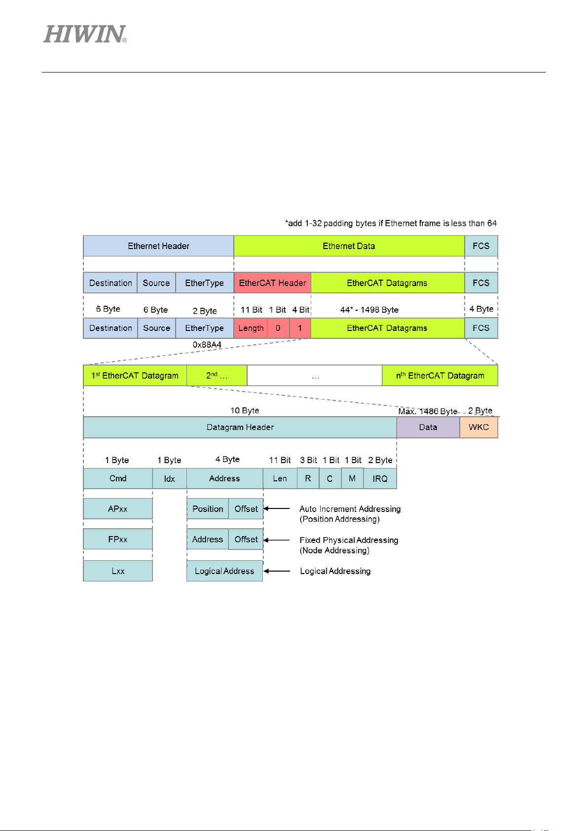
2.3 EtherCAT frame structure
EtherCAT frames (Ethernet frames with EtherType 0x88A4, see Figure 2.3.1) are processed by EtherCAT
Slave Controller (ESC) on the fly. EtherCAT datagrams are processed before the complete frame is
received. If frame checksum is invalid, the slave will set the data invalid for local application.
2-4 HIWIN MIKROSYSTEM Corp.
Figure 2.3.1

E1 Series Servo Drive EtherCAT(CoE) Communications Command Manual EtherCAT Communication
MD08UE01-1812
0
NOP
No operation
Slave ignores command.
s address. Slave writes data into
ocation if
y location. All
EtherCAT datagram if received address is zero,
writes the data into memory
otherwise slave writes the data into memory
2.3.1 EtherCAT commands
Table 2.3.1.1
CMD Abbr. Name Description
1 APRD Auto increment read
2 APWR Auto increment write
3 APRW Auto increment read write
4 FPRD Configured address read
5 FPWR Configured address write
6 FPRW Configured address read write
7 BRD Broadcast read
8 BWR Broadcast write
9 BRW Broadcast read write
Slave increases address. Slave puts read data into
EtherCAT datagram if received address is zero.
Slave increase
memory location if received address is zero.
Slave increases address. Slave puts read data into
EtherCAT datagram and writes data into the same
memory location if received address is zero.
Slave puts read data into EtherCAT datagram if
address matches one of its configured addresses.
Slave writes data into memory location if address
matches one of its configured addresses.
Slave puts read data into EtherCAT datagram and
writes data into the same memory l
address matches one of its configured addresses.
All slaves put logical OR of data of memory area
and data of EtherCAT datagram into EtherCAT
datagram. All slaves increase position field.
All slaves write data into memor
slaves increase position field.
All slaves put logical OR of data of memory area
and data of EtherCAT datagram into EtherCAT
datagram, and write data into memory location. All
slaves increase position field.
used.
BRW is typically not
10 LRD Logical memory read
11 LW R Logical memory write
12 LRW Logical memory read write
13 ARMW Auto increment read multiple write
14 FRMW Configured address read multiple write
HIWIN MIKROSYSTEM Corp. 2-5
Slave puts read data into EtherCAT datagram if
received address matches one of the configured
FMMU areas for reading.
Slaves writes data to into memory location if
received address matches one of the configured
FMMU areas for writing.
Slave puts read data into EtherCAT datagram if
received address matches one of the configured
FMMU areas for reading. Slaves writes data into
memory location if received address matches one
of the configured FMMU areas for writing.
Slave increases address. Slave puts read data into
otherwise slave
location.
Slave puts read data into EtherCAT datagram if
address matches one of its configured addresses,
location.

E1 Series Servo Drive EtherCAT(CoE) Communications Command Manual EtherCAT Communication
MD08UE01-1812
Fail 0 Succeed
+1
Fail 0 Succeed
+1
Fail
0
Write succeed
+2
Read write succeed
+3
2.3.2 WKC (Working Counter)
Working Counter (W KC) is a 16-bit field placed at the end of each EtherCAT datagram. The addressed
slave increases WKC based on Table 2.3.2.1 for the master to check if the number of nodes of the
corresponding EtherCAT PDU is in line with expectations.
Table 2.3.2.1
Command Data type Increment
Read
Write
Read write
Read succeed +1
2-6 HIWIN MIKROSYSTEM Corp.
E1 Series Servo Drive EtherCAT(CoE) Communications Command Manual EtherCAT Communication
MD08UE01-1812
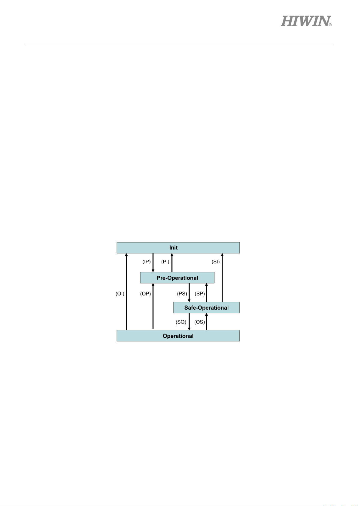
2.4 EtherCAT State Machine
EtherCAT State Machine (ESM) is responsible for the coordination of the applications for master and
slaves at start up and during operation. State changes are typically initiated by the requests of the master.
They are acknowledged by the local application after the associated operations have been executed.
Unsolicited state changes of the local application are also possible.
E1-series drive supports the following four states.
Init
Pre-Operational
Safe-Operational
Operational
The states and the allowed state changes are shown in Figure 2.4.1.
Figure 2.4.1
Note: Not all state changes are possible. For example, the transition from ‘Init’ to ‘Operational’ requires
the following sequence: Init → Pre-Operational → Save-Operational → Operational.
HIWIN MIKROSYSTEM Corp. 2-7

E1 Series Servo Drive EtherCAT(CoE) Communications Command Manual EtherCAT Communication
MD08UE01-1812
(PreOp)
No Process Data communication
Drive remains in Safe state (Outputs are blocked)
Master sends valid Outputs
Wait for AL Status register confirmation
Operational
(Op)
PreOp
O
-
-
SafeOp
O
O
-
Table 2.4.1
State / State change Description
Init
No communication on Application Layer (AL)
Master accesses to Data Link (DL)-Information registers
Master configures registers
- DL address register
Init to PreOp
(IP)
- SyncManager channels for Mailbox communication
Master requests ‘Pre-Operational’ state
- Master sets AL Control register
Wait for AL Status register confirmation
Pre-Operational
Mailbox communication on AL
Master configures parameters via Mailbox
- e.g., Process Data Mapping
Master configures DL Register
PreOp to SafeOp
(PS)
- SyncManager channels for Process Data communication
- FMMU channels
Master initializes DC clock synchronization
Master requests ‘Safe-Operational’ state
Wait for AL Status register confirmation
Safe-Operational
(SafeOp)
Mailbox communication on AL
Process Data communication (Only Inputs are valid)
SafeOp to Op
(SO)
Master requests ‘Operational’ state (AL Control / Status)
Inputs and Outputs are valid
ESM state
Init - - -
Op O O O
Table 2.4.2
Communication operation
send / receive SDO (Mailbox) TxPDO RxPDO
2-8 HIWIN MIKROSYSTEM Corp.

E1 Series Servo Drive EtherCAT(CoE) Communications Command Manual EtherCAT Communication
MD08UE01-1812
ESM
PDS
Not ready to switch on
O - -
O
Switch on disabled
O O O
O
Ready to switch on
- O O
O
Switched on
- O O
O
Fault reaction active
O O O
O
Fault
O O O
O
Table 2.4.3 shows the relationship between PDS (Power Drive System) and ESM states.
Table 2.4.3
Init PreOp SafeOp Op
Operation enabled - O O O
Note:
1. When ESM state receives a transition command from PreOp, SafeOp and Op to Init, PDS state
changes to Switched on disabled.
2. When PDS is at Operation enabled state but ESM changes to other states except Op, an error
occurs and PDS state changes to Fault.
3. Change of PDS state has no effect on ESM state.
HIWIN MIKROSYSTEM Corp. 2-9
E1 Series Servo Drive EtherCAT(CoE) Communications Command Manual EtherCAT Communication
MD08UE01-1812
2.5 Synchronous mode
There are two types of synchronous mode, DC and FreeRun.
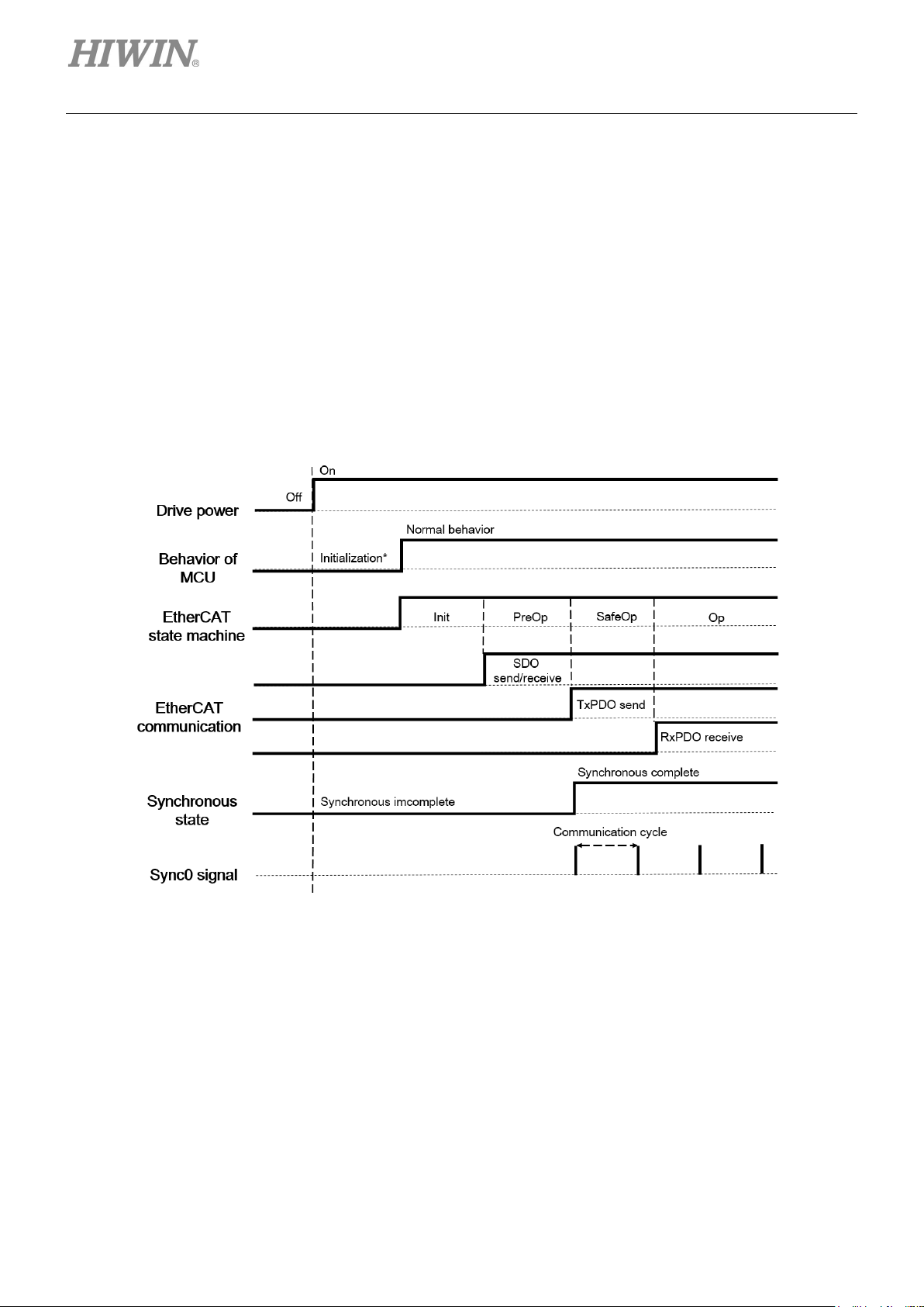
2.5.1 DC
The synchronization of EtherCAT communication is based on DC. The local cycle and the servo process
of the drive are triggered by Sync0 event.
2-10 HIWIN MIKROSYSTEM Corp.
Figure 2.5.1.1
E1 Series Servo Drive EtherCAT(CoE) Communications Command Manual EtherCAT Communication
MD08UE01-1812
06010000h
Unsupported access to an object
06010002h
Attempt to write to a read-only object
06020000h
The object does not exist in the object dictionary
06040042h
Number and length of the objects to be mapped would exceed PDO length
06090030h
Value range of parameter exceeded (only for write access)
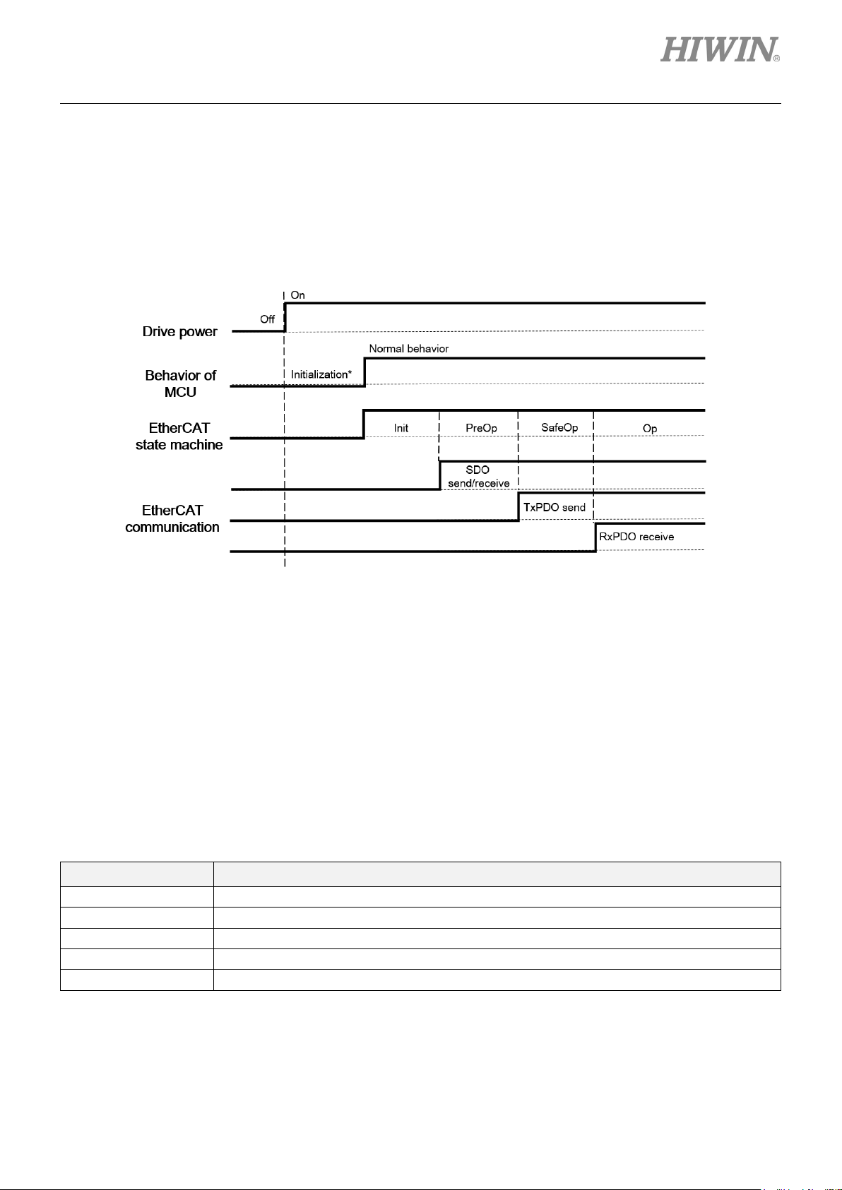
2.5.2 FreeRun
FreeRun is started by the local timer interrupt of the drive. The local cycle runs independently of the
communication cycle and the master cycle.
Figure 2.5.2.1
Note: The PDO transmission interval should not be less than 250 μs.
2.6 SDO abort code
When SDO communication error occurs, SDO abort code is returned. The supported SDO abort codes
are listed in Table 2.6.1.
Table 2.6.1
Value Descritpion
HIWIN MIKROSYSTEM Corp. 2-11

E1 Series Servo Drive EtherCAT(CoE) Communications Command Manual EtherCAT Communication
MD08UE01-1812
2.7 Emergency message
When an error occurs, a slave notifies the master of the emergency message through the mailbox
communication. An emergency message consists of 8 Bytes of data, as Table 2.7.1 shows.
Table 2.7.1
Byte 0 1 2 3 4 5 6 7
Description
Error code
(603Fh)
(L) (H)
Error register
(1001h)
Reserved
The validity or the invalidity of emergency message transmission can be set via 10F3h (diagnosis history).
The default is validity.
Error code: the same value as 603Fh (error code)
Error register: the same value as the one in 1001h (error register)
2-12 HIWIN MIKROSYSTEM Corp.
E1 Series Servo Drive EtherCAT(CoE) Communications Command Manual EtherCAT Communication
MD08UE01-1812
2.8 PDO (Process Data Object)
The PDOs are used to transfer data during cyclic communication in realtime. RxPDOs receive data from
the master. TxPDOs send status from the drive to the master. Objects updated by PDO are not updated
by SDO.
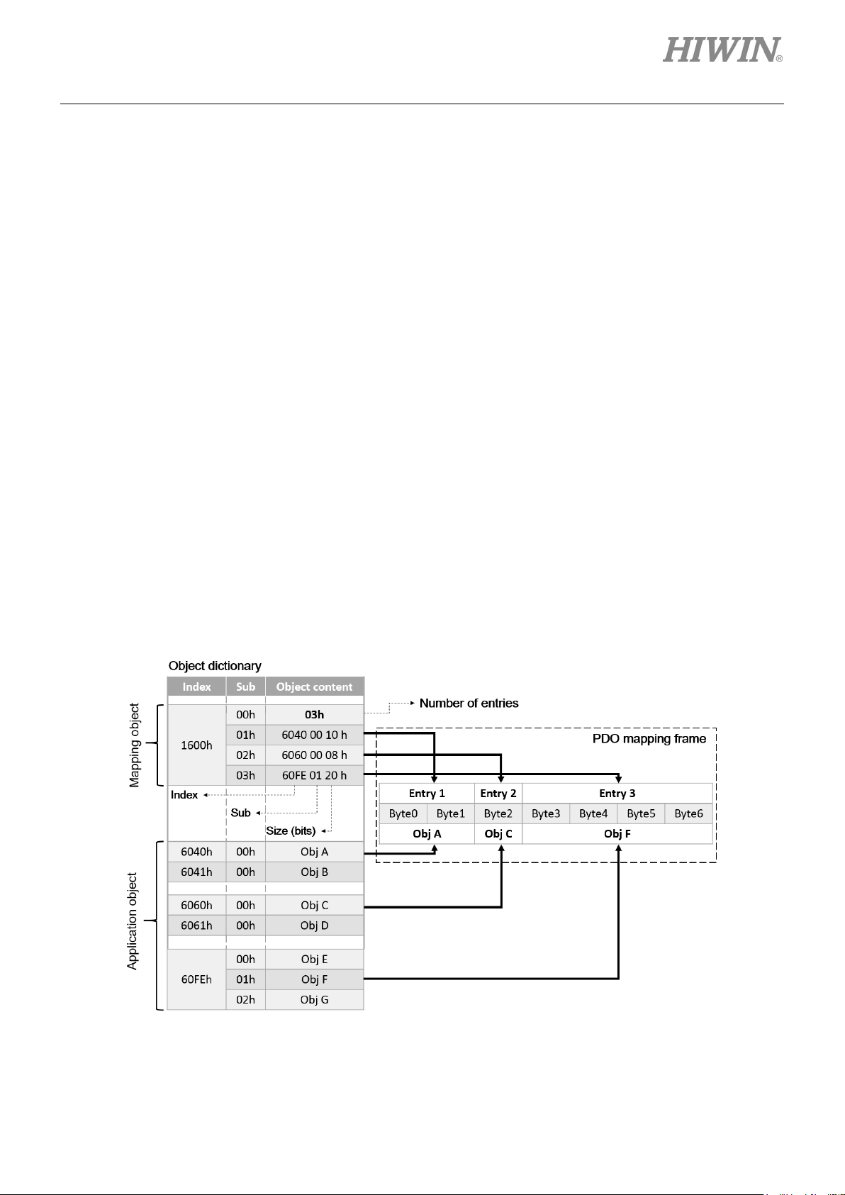
2.8.1 PDO mapping object
Before using PDO communication, application objects should be mapped to the PDO mapping object.
Each PDO mapping object can store up to eight application objects, and the maximum length of the PDO
mapping object is 32 Bytes. In the object dictionary, index 1600h to 1603h are for RxPDOs, and index
1A00h to 1A03h are for TxPDOs.
An example of PDO mappings is shown in Figure 2.8.1.1. Three application objects (Obj A, Obj C and Obj
F) are mapped to the PDO mapping object 1600h. Please refer to Section 3.1.1 for the default of each
PDO mapping object.
Figure 2.8.1.1
HIWIN MIKROSYSTEM Corp. 2-13
E1 Series Servo Drive EtherCAT(CoE) Communications Command Manual EtherCAT Communication
MD08UE01-1812
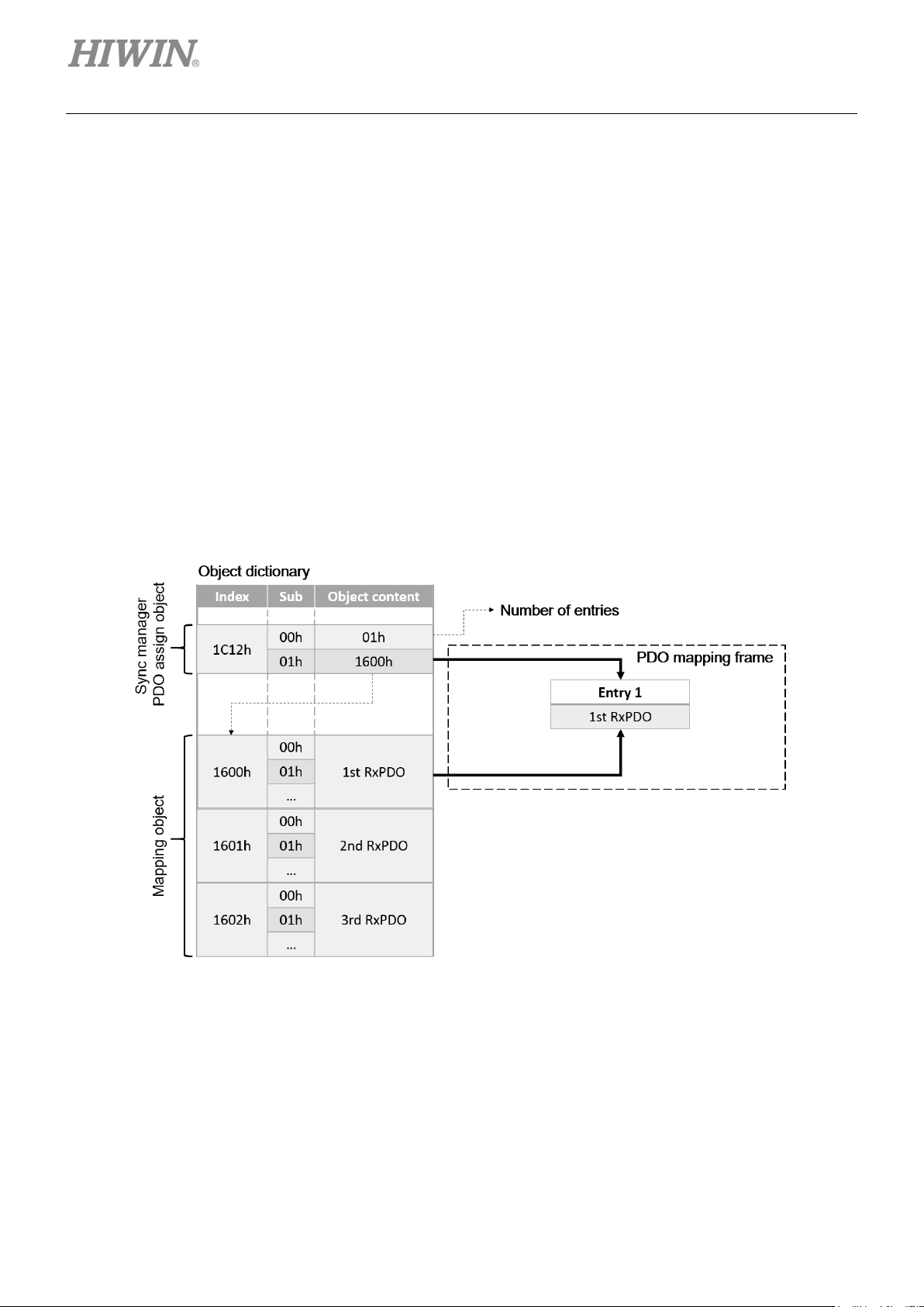
2.8.2 PDO assign object
Besides PDO mappings described above, it is also necessary to assign PDO mapping table in
SyncManager. SyncManager PDO assignment objects describe the relationship between PDO mapping
tables and SyncManagers.
In E1-series drive, 1C12h for RxPDO (SyncManager 2) and 1C13h for TxPDO (SyncManager 3) are set
to be SyncManager assign objects. The maximum number of mapping objects can be mapped to an assign
object is one. Please refer to Section 3.1.2 for the complete procedure of setting PDO mapping.
An example of SyncManager PDO assignment is shown in Figure 2.8.2.1. 1C12h is mapped to the assign
object 1600h, which means the first set of the application objects will be used for RxPDO communication.
2-14 HIWIN MIKROSYSTEM Corp.
Figure 2.8.2.1
 Loading...