

D2 Drive User Guide v1.8
D2 Drive User Guide
Version 1.8
December 7, 2016
HIWIN Mikrosystem Corp.

D2 Drive User Guide v1.8 Table of Contents
Table of Contents
1. About the User Guide ....................................................................................................... 1
1.1. Instructions before use ................................................................ ........................... 2
1.2. Safety instructions .................................................................................................. 4
2. Specifications ................................................................................................................... 7
2.1. Drive information .................................................................................................... 8
2.1.1. Safety certification ........................................................................................ 8
2.1.2. Nameplate information .................................................................................. 8
2.1.3. Model number ............................................................................................... 9
2.2. Drive specifications .............................................................................................. 10
2.3. Drive dimensions .................................................................................................. 14
2.4. Drive installation ................................................................................................... 21
2.5. Computer requirements ........................................................................................ 22
3. Operation Principles ....................................................................................................... 23
3.1. Operation modes .................................................................................................. 24
3.1.1. Position mode ............................................................................................. 24
3.1.2. Velocity mode ............................................................................................. 24
3.1.3. Force/torque mode ..................................................................................... 25
3.1.4. Stand-alone mode ...................................................................................... 25
3.2. Encoder type ........................................................................................................ 26
3.3. Encoder signal output ........................................................................................... 27
3.4. Path planning ....................................................................................................... 28
3.5. Servo loops and gains .......................................................................................... 30
3.6. Gain margin and phase margin ............................................................................ 31
3.6.1. Nyquist diagram .......................................................................................... 31
3.6.2. Bode diagram ............................................................................................. 32
3.7. Move and settling ................................................................................................. 34
3.8. Error compensation .............................................................................................. 35
3.9. Velocity ripple ....................................................................................................... 36
3.10. Enable .................................................................................................................. 37
3.11. Common physical quantities ................................................................................. 38
4. Wiring ............................................................................................................................. 39
4.1. System configuration and wiring ........................................................................... 40
4.1.1. System wiring diagram ............................................................................... 40
4.1.2. CN1 power ................................................................................................. 43
4.1.3. CN2 brake/motor power .............................................................................. 47
4.1.4. CN3 USB communication ........................................................................... 48
4.1.5. CN4 Modbus communication ...................................................................... 48
4.1.6. CN5 Modbus communication/safety function .............................................. 49
4.1.7. CN6 control signal ...................................................................................... 50
4.1.8. CN7 encoder .............................................................................................. 52
4.1.9. CN8 EtherCAT communication ................................................................... 52
4.1.10. CN13/CN14 extension I/O signal ................................................................ 53
4.2. Drive accessories ................................................................................................. 54
4.3. Main power wiring ................................................................................................ 58
4.3.1. AC power wiring (single-phase) .................................................................. 58
4.3.2. AC power wiring (three-phase) ................................................................... 59
4.4. Multiple drives connection .................................................................................... 60
4.5. I/O signal wiring .................................................................................................... 62
4.5.1. Digital input wiring....................................................................................... 62
4.5.2. Digital output wiring .................................................................................... 63
4.6. Wiring examples for control commands ................................................................ 65
HIWIN Mikrosystem Corp. ii

D2 Drive User Guide v1.8 Table of Contents
4.6.1. System wiring diagram for pulse command................................................. 65
4.6.2. System wiring diagram for voltage command .............................................. 73
4.6.3. System wiring diagram for PWM command ................................................ 75
5. Drive Configuration ......................................................................................................... 79
5.1. Installation and communication ............................................................................ 80
5.1.1. Setup files ................................................................................................... 80
5.1.2. Communication setup ................................................................................. 81
5.1.3. HMI main window ....................................................................................... 83
5.2. Configuration center ............................................................................................. 86
5.2.1. Motor configuration ..................................................................................... 86
5.2.2. Encoder configuration ................................................................................. 88
5.2.3. Operation mode configuration ..................................................................... 94
5.2.4. Modbus communication configuration ......................................................... 96
5.2.5. Completing configuration procedure ........................................................... 97
5.3. Auto phase center ................................................................................................ 98
5.3.1. Function description .................................................................................... 98
5.3.2. Pre-operation .............................................................................................. 98
5.3.3. Setting procedure ....................................................................................... 99
5.3.4. Troubleshooting ........................................................................................ 100
5.4. Auto tune center ................................................................................................. 101
5.4.1. Function description .................................................................................. 101
5.4.2. Announcements ........................................................................................ 104
5.4.3. Troubleshooting ........................................................................................ 104
5.5. I/O center ........................................................................................................... 106
5.5.1. Digital input ............................................................................................... 106
5.5.2. Digital output ............................................................................................. 117
5.5.3. Analog output ........................................................................................... 122
5.5.4. Extension I/O ............................................................................................ 123
5.6. In-position signal setting ..................................................................................... 124
5.7. Homing configuration ......................................................................................... 126
5.7.1. Go left and right for homing ...................................................................... 128
5.7.2. Use near home sensor/index for homing .................................................. 130
5.7.3. Use multi-turn absolute encoder for homing.............................................. 132
5.7.4. Use homing methods in CiA 402 protocol ................................................. 133
5.8. Save parameters to Flash and recover to factory default .................................... 138
5.8.1. Save parameters to Flash ......................................................................... 138
5.8.2. Recover to factory default ......................................................................... 138
5.9. Parameter setting examples via HMI .................................................................. 140
5.9.1. Position mode ........................................................................................... 140
5.9.2. Velocity mode ........................................................................................... 142
5.9.3. Force/Torque mode .................................................................................. 143
5.9.4. Stand-alone mode .................................................................................... 145
6. Drive Tuning ................................................................................................................. 147
6.1. Status display and quick view ............................................................................. 148
6.1.1. Status display ........................................................................................... 148
6.1.2. Quick view ................................................................................................ 148
6.1.3. Software shortcuts .................................................................................... 149
6.2. Performance center ............................................................................................... 150
6.3. Scope ................................ ................................................................ ................. 153
6.4. Data collection .................................................................................................... 155
6.4.1. Function description .................................................................................. 155
6.4.2. Data collection via PDL ............................................................................. 156
6.5. Plot view ............................................................................................................. 157
6.5.1. Graphic display mode ............................................................................... 157
6.5.2. Save/open file ........................................................................................... 161
HIWIN Mikrosystem Corp. iii

D2 Drive User Guide v1.8 Table of Contents
6.5.3. Mathematical operation ............................................................................ 162
6.6. Advanced gains .................................................................................................. 165
6.6.1. Filter ......................................................................................................... 165
6.6.2. Acceleration feed-forward ......................................................................... 167
6.6.3. Schedule gains and velocity loop gain ...................................................... 169
6.6.4. Analog input.............................................................................................. 172
6.6.5. Current loop .............................................................................................. 173
6.6.6. Vibration suppression feature ................................................................... 173
6.6.7. Friction compensation ............................................................................... 177
6.7. Loop constructor................................................................................................. 179
6.7.1. Load/Save file ........................................................................................... 180
6.7.2. Tool .......................................................................................................... 181
6.7.3. Filter ......................................................................................................... 184
6.7.4. Gain tuning ............................................................................................... 185
6.7.5. Spectrum analysis .................................................................................... 186
6.8. Encoder signal confirmation ............................................................................... 187
6.9. Error map function .............................................................................................. 188
6.9.1. Set error map ............................................................................................ 188
6.9.2. Enable error map ...................................................................................... 190
6.9.3. Save/open error map ................................................................................ 190
6.9.4. Change start position ................................................................................ 191
6.10. Backlash compensation ...................................................................................... 196
7. LCD Operation .............................................................................................................. 197
7.1. LCD function ...................................................................................................... 198
7.1.1. Panel description ................................................................ ...................... 198
7.1.2. Operation page description ....................................................................... 198
7.2. Parameter initialization via LCD .......................................................................... 200
7.3. Home page ......................................................................................................... 202
7.4. Display parameters page .................................................................................... 204
7.5. Change parameters page ................................................................................... 206
7.5.1. Save to Flash ............................................................................................ 207
7.5.2. Parameter edit function ............................................................................. 208
7.5.3. Advanced parameter zone ........................................................................ 211
7.6. Actions page ...................................................................................................... 219
7.6.1. Enable/Disable ......................................................................................... 220
7.6.2. JOG .......................................................................................................... 221
7.6.3. Absolute coordinate motion ...................................................................... 222
7.6.4. Auto tune .................................................................................................. 222
7.6.5. Set position to zero ................................................................................... 223
7.7. Parameter setting examples via LCD ................................................................. 224
7.7.1. Position mode ........................................................................................... 224
7.7.2. Velocity mode ........................................................................................... 227
7.7.3. Force/torque mode ................................................................................... 229
7.7.4. Stand-alone mode .................................................................................... 231
8. Protection Function ....................................................................................................... 233
8.1. Motion protection ................................................................................................ 234
8.2. Position and velocity errors protection ................................................................ 237
8.2.1. Position error limit ..................................................................................... 237
8.2.2. Position error and velocity error warnings ................................................. 237
8.3. Brake output ....................................................................................................... 238
8.4. Limit protection ................................................................................................... 242
8.4.1. Hardware limit protection ................................ .......................................... 242
8.4.2. Software limit protection............................................................................ 242
8.5. Over temperature protection ............................................................................... 244
8.5.1. Soft-thermal protection ............................................................................. 244
HIWIN Mikrosystem Corp. iv

D2 Drive User Guide v1.8 Table of Contents
8.5.2. Drive over temperature protection ............................................................. 244
8.6. Over voltage protection ...................................................................................... 245
9. Troubleshooting ............................................................................................................ 249
9.1. Drive’s status indicator ....................................................................................... 250
9.2. Drive’s errors and warnings ................................................................................ 251
9.2.1. Status display area on Lightening HMI ...................................................... 251
9.2.2. LCD status ................................................................................................ 251
9.2.3. Errors and warnings log ............................................................................ 252
9.2.4. Error at loading PRM file ........................................................................... 254
9.3. Error codes and troubleshooting ......................................................................... 255
9.4. Warning codes and troubleshooting ................................................................... 258
9.5. Troubleshooting for common issues ................................................................ ... 262
A. Axis Enable Setting ....................................................................................................... 265
A.1. Start enable method .............................................................................................. 266
A.2. Confirm enable status via HMI .............................................................................. 267
B. Parameter Comparison ................................................................................................. 269
B.1. Comparing parameters in RAM and Flash ............................................................ 270
C. Update Firmware & Load PDL ...................................................................................... 273
C.1. Update drive’s firmware ........................................................................................ 274
C.2. Load PDL program into drive ................................................................................ 277
D. Modbus Communication ............................................................................................... 279
D.1. Modbus communication specification .................................................................... 280
D.2. Function code ....................................................................................................... 281
D.3. Modbus objects ..................................................................................................... 285
D.3.1. Input register .............................................................................................. 285
D.3.2. Holding register .......................................................................................... 289
E. EMC Solution ................................................................................................................ 291
E.1. Common-mode motor filter .................................................................................... 292
E.2. Motor power cable with magnetic rings ................................................................. 295
HIWIN Mikrosystem Corp. v

D2 Drive User Guide v1.8 Table of Contents
Version
Date
Applicability
Remarks
1.0
2012-06-05
D2-series drive
Frist release.
1.1
2012-08-30
D2-series drive
Renew Figure 2-1 and Figure 2-2.
Renew CN6 connector part number.
1.2
2014-05-15
D2-series drive
(1) Update the description of LCD operation.
(2) Update the description according to motor model.
1.3
2014-08-20
D2-series drive
(1) Add the information for D2T drive.
(2) Renew the dimension of D2 drive.
(3) Add the dimension of D2 drive with EtherCAT
(CoE/mega-ulink).
(4) Remove the brake wiring without a relay.
(5) Remove the input function of clear position error.
(6) Add the description of mega-ulink
communication.
(7) Add the description of using PDL to assist with
data capture.
(8) Add motor models with HIWIN 17 encoder to
Table 4.1.
1.4
2014-11-21
D2-series drive
(1) Modify the model number by combining
D2-model and D2T-model drives.
(2) Add the description of ZeroTune.
(3) Add the description of setting parameters to
factory default.
(4) Renew the description of LCD operation.
(5) Add LCD common parameters table.
(6) Add the input range of LCD parameters.
(7) Add the PDL information to drive specifications.
(8) Add the description of VSF operation.
1.8
2016-12-07
D2 MDP 0.043 or
above
D2COE MDP 0.119
or above
Lightening 0.189 or
above
Re-write and re-organize this User Guide based on
Chinese version of D2 Drive User Guide v1.8.
Revision History:
HIWIN Mikrosystem Corp. vi

D2 Drive User Guide v1.8 1. About the User Guide
1. About the User Guide
1. About the User Guide ....................................................................................................... 1
1.1. Instructions before use ................................................................ ........................... 2
1.2. Safety instructions .................................................................................................. 4
HIWIN Mikrosystem Corp. 1

D2 Drive User Guide v1.8 1. About the User Guide
Attention
‧Maximum ambient temperature for this series drives is 55 ℃.
‧This product can be installed only on the environment with the pollution level being
2.
‧The rated input voltage of drive is 240 V. Hence, the power supply voltage cannot be
over than 240 V. A short-circuit current shall not exceed 5,000 A.
‧The drive does not provide a motor over-temperature sensing, while not have a motor
over-temperature protection.
‧The short-circuit protection of drive cannot be used as a shunt-circuit protection. The
shunt-circuit protection must be chosen in accordance with US National Electrical
Code (NEC) and local regulations.
‧Before starting to inspect the product, turn off the power and wait at least five
minutes. Then, use a multi-meter or a similar instrument to check that the residual
voltage between P and N terminals has dropped to the safety level (50 Vdc or lower)
to avoid electric shock.
1.1. Instructions before use
This document is suitable for D2-series drives, included D2 model and D2T model. Read the
User Guide carefully before using the product. HIWIN Mikrosystem Corp. (“the Company”) will
not take any responsibility for damages, accidents, or injuries caused by the installation or use
that is not performed according to these instructions.
Do not dismantle or modify the product. The product has been subject to structural
calculations, computer simulations, and physical tastings to verify its design. Do not
dismantle or modify the product without the consent of the professional technician of the
Company. The Company does not take any responsibility for accidents or damages
resulting from such dismantling or modification.
Before installing or using the product, check the external appearance and ensure that there
is no damage on the product surface. If any damage is identified, contact the Company or
one of the Company’s distributors immediately.
Refer to performance specifications on the product label or manufacturer's document before
using the product. Install the product based on these performance limits and installation
instructions indeed.
Read the specification of power voltage on the label before using the product and confirm
that the power supply meets the product requirement. The Company does not take any
responsibility for product damages or personal injuries resulting from the incorrect power
supply.
Do not use the product over the rated load. The Company does not take any responsibility
for damages or injuries resulting from such misuse.
Do not use the product in an environment where shocks may occur. The Company does not
take any responsibility for damages, accidents, or injuries resulting from such shocks.
If the drive has any error, refer to Section 9.5. Troubleshooting for common issues. Follow
instructions to turn off drive’s power to perform troubleshooting. After the error is eliminated,
turn on drive’s power again.
Do not try to repair any produce’s malfunction. The product can only be repaired by the
qualified technician.
The warranty period is one year from the ex-factory date. The Company does not take any
responsibility for product replacement or repair caused by the inappropriate use or natural
disasters. (Refer to notes and installation instructions in the User Guide.)
HIWIN Mikrosystem Corp. 2

D2 Drive User Guide v1.8 1. About the User Guide
Warning
At installing or exchanging motor power
cables, if the correct sequence of
connection is not followed, the motor may
run abnormally. It is possible to cause injury
to persons or damage to equipment. Please
use correctly labelled cables.
Warning
Each motor model has its own rated
maximum payload. If applying more than
such payload to the motor, it may cause
abnormal motion, damage to equipment,
or injury to persons.
Warning
If users select to use own made motor
encoder cables, please check the User
Guide carefully or contact our service
department. The wrong connection of such
cable may cause abnormal motion or injury
to persons.
Warning
During the usage of motor, in case of the
careless removal of encoder connector
from the drive, please do not hot plug it
back to the drive. It may cause abnormal
motion, damage to equipment, or injury
to persons.
Warning
Applying the open type of optical feedback
system (e.g. optical scale), please note that
if the scale is stained or scratched, it may
cause abnormal motion, damage to the
motor or equipment, or injury to persons.
Warning
When the motor is regularly under the
operation, and careless touch or collision
to the encoder connector on the drive, it
is recommended to power cycle the
drive, or it may cause abnormal motion,
damage to equipment, or injury to
persons.
Warning
Applying the open type of magnetic
feedback system (e.g. magnetic scale),
please note that if the strong magnetic
object comes close to the scale, it may
cause abnormal motion, damage to the
motor or equipment, or injury to persons.
Warning
During the usage of motor, please do not
unplug the encoder connector when it is
not powered off, move the motor, and
then plug it back to the drive, or it may
cause abnormal motion, damage to
equipment, or injury to persons.
Risks specifically identified:
HIWIN Mikrosystem Corp. 3
D2 Drive User Guide v1.8 1. About the User Guide
Warning
Inappropriate operations may cause dangers resulting in the serious injury or death.
Inappropriate operations may cause dangers resulting in the disability, minor injury, or
material damage.
Attention
Actions marked Attention may have serious consequences under different situations.
All such instructions are important and must be followed.
Prohibited
Indicate that the action is forbidden and must not be done.
Required
Indicate that the action is compulsory and must be done.
Danger
‧
Always ensure that the drive is correctly earthed by using PE bar in the switch
cabinet as reference potential. Safety is not guaranteed if there is no low-ohm
earthing.
‧
Power connections may be live even if the motor does not move. Never disconnect
electrical connections of motor and drive as live. In the worst case, electric arcs
may form and cause personal injury and damage contacts.
‧
After disconnecting the drive from the power supply, wait at least five minutes
before touching live parts (e.g. contacts, threaded bolts etc.) or breaking
connections. For your own safety, measure the voltage in the intermediate circuit
and wait until it has fallen below 40 Vdc.
1.2. Safety instructions
Read the User Guide carefully before the installation, transportation, maintenance, and
inspection. Ensure that the product is used correctly.
Users should read the EM information, safety information, and all related instructions before
using the product.
The safety instructions in the User Guide are categorized into “Warning”, “Attention”,
“Prohibited”, and “Required”.
HIWIN Mikrosystem Corp. 4
D2 Drive User Guide v1.8 1. About the User Guide
Usage instructions
Warning
Do not touch the terminal or inside part when it is powered to
avoid electric shock.
Do not touch the terminal or inside within 10 minutes from the
power off. The residual voltage may cause electric shock.
Do not change the wiring when it is powered to avoid electric
shock.
Do not cut the cable, apply too much stress to it, or place heavy
objects on it. Laying the cable between objects may cause fire or
electric shock.
Attention
Do not install the product in the place exposed to moisture or
erosion, or in an environment containing ignitable gas. Do not
use the product close to any flammable objects.
Storage
Prohibited
Do not store the product in the place exposed to water, moisture,
direct sunlight, harmful gas, or liquids.
Handling
Attention
Be careful of handling the product and avoid damaging it.
Use appropriate handling methods and do not apply too much
pressure to the case.
The product shall not be stacked too high to avoid collapsing.
Installation location
Required
Do not install the product in the place exposed to high
temperatures, high humidity or flying dust, iron powder, or
cutting powder.
Install the product in the place where the ambient temperature
meets the specification of User Guide. Use one cooling fan if the
temperature is potentially high.
Do not install the product in the place exposed to direct sunlight.
Since the product does not have one waterproof or
moisture-proof case, do not use it outdoors or install it in the
place where water or other liquid exists.
Install the product in the place with the low vibration.
When the motor continues moving, the heat is generated due to
the use frequency. Use one cooling fan, or set to standby status
when the motor stops. So that, the ambient temperature of motor
does not exceed its specific value.
HIWIN Mikrosystem Corp. 5

D2 Drive User Guide v1.8 1. About the User Guide
Installation
Attention
Do not place any heavy objects on the product to avoid damage.
Do not mix with debris to avoid fire.
Ensure that the product is installed in the required direction to
avoid fire.
Protect the product from the strong impact to avoid collapse or
damage.
The weight of mounting body must be taken into account during
installation. Inappropriate installation may cause damage.
Install the product on a metal or noncombustible object to avoid
fire.
Wiring
Attention
Be correct and reliable wiring, otherwise it may cause motor to
out of control or burn out, and make damage or fire.
Operation and transportation
Attention
Ensure that the specification of power source is correct to avoid
damage or fire.
The motor may suddenly start after the power is recovered
instantly. Do not come too close to machine.
Required
Wire an external line for emergency stop to stop the operation
and to cut off the power at any time.
Maintenance
Prohibited
Do not dismantle or modify the product.
Do not attempt to repair any product malfunction. Please send it
back to the professional technician of the Company for repair.
HIWIN Mikrosystem Corp. 6

D2 Drive User Guide v1.8 2. Specifications
2. Specifications
2. Specifications ................................................................................................................... 7
2.1. Drive information .................................................................................................... 8
2.1.1. Safety certification ........................................................................................ 8
2.1.2. Nameplate information .................................................................................. 8
2.1.3. Model number ............................................................................................... 9
2.2. Drive specifications .............................................................................................. 10
2.3. Drive dimensions .................................................................................................. 14
2.4. Drive installation ................................................................................................... 21
2.5. Computer requirements ........................................................................................ 22
HIWIN Mikrosystem Corp. 7
D2 Drive User Guide v1.8 2. Specifications
EMC
EN 61800-3: 2004 (Category C2)
EN 61000-3-2: 2006/A1: 2009/A2: 2009
EN 61000-3-3: 2008
IEC CISPR 11: 2009/A1: 2010
IEC 61000-4-2: 2008
IEC 61000-4-3: 2006/A1: 2007/A2: 2010
IEC 61000-4-4: 2004
IEC 61000-4-5: 2005
IEC 61000-4-6: 2008
IEC 61000-2-1: 1990
IEC 61000-2-4: 2003
IEC 60146-1-1: 1993
LVD
IEC 61800-5-1: 2007 (2nd Edition)
EN 61800-5-1:2007
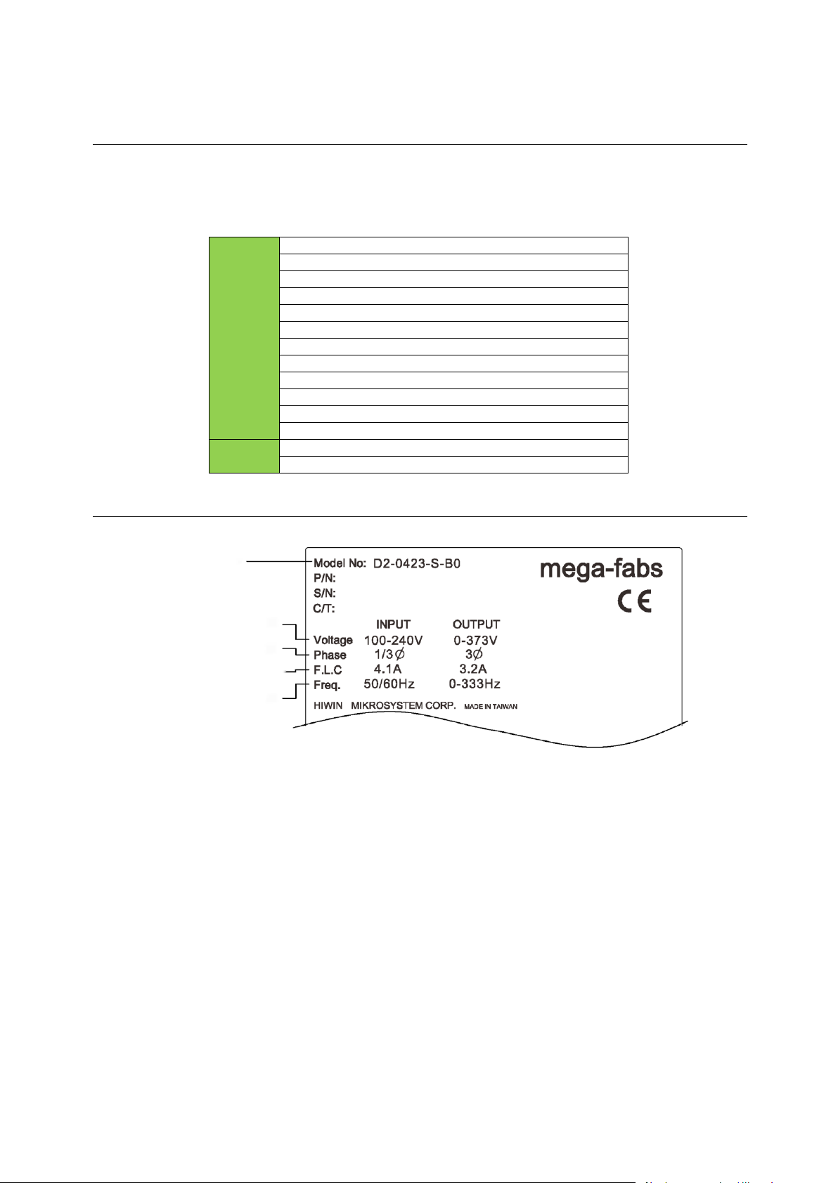
Model No.
Input/output voltage
Rated input/output current
Input/output frequency
Phases
2.1. Drive information
2.1.1. Safety certification
The drive complies with the following safety regulations.
CE Compliance
Table 2-1
2.1.2. Nameplate information
Fig. 2-1
HIWIN Mikrosystem Corp. 8

D2 Drive User Guide v1.8 2. Specifications
Column
1 2 2a 3 4 5 6 7 8 9 10
11
12
Example
D 2 - 0 4 2 3 - S - B 0
2.1.3. Model number
D2-series drives:
Product
D2-series drive…= D2
Type
17-bit encoder only…….= T
13-bit encoder only........=Blank
Rated output
100 W…………………...........………….= 01
400 W……………………...……………..= 04
1.0 KW………….……….…....................= 10
2.0 KW……………………………………= 20
Voltage range
1/3-phase 110/220 Vac….....………..…….…………..= 23
3-phase 220 Vac…………….……………..........……..= 32
Interface
Standard………………………………………………………………….= S
EtherCAT (CoE)………………………….…………….….….………...= E
EtherCAT (mega-ulink)…………………..…………………………..…= F
Standard with extension I/O module..….……..……………………....= K
Standard with Modbus………………………………………………….= T
Frame size
A frame (suggestion: 100 W rated output)…….…………..…………..…………..= A
B frame (suggestion: 400 W rated output)……….……………………..………....= B
C frame (suggestion: 1.0 KW rated output)…………………………..…………...= C
D frame (suggestion: 2.0 KW rated output)…………………………..…………...= D
Encoder type
13-bit less-wire incremental encoder...…..………………….…..…………….….……....= 0
17-bit serial incremental encoder (HIWIN17)……………………………………………..= 4
Dual loop (full closed loop) and 17-bit serial absolute encoder………..……………….= 5
Note:
(1) The standard model supports the pulse and +/- 10 V input interfaces.
(2) The EtherCAT (CoE) and EtherCAT (mega-ulink) models do not have the extension I/O
module and Modbus module.
(3) The frame D model requires the voltage range of 3-phase 220 Vac.
(4) D2 model does not support the extension I/O module and the rated output of 2.0 KW.
(5) D2T frame A, B, and C models do not have the Modbus module.
(6) For the dual-loop model, the rotary encoder should be the 17-bit serial absolute
encoder and the linear encoder should be the digital AqB encoder.
(7) The EtherCAT (CoE) model does not support the dual-loop control.
Fig. 2-2
HIWIN Mikrosystem Corp. 9

D2 Drive User Guide v1.8 2. Specifications
Basic specifications
Input power
220V
Main power
Frame
A-C
Single/three-phase, 200 - 240 Vac 50/60Hz
Frame
D
Three-phase, 200 - 240 Vac 50/60Hz
Control
power
Frame
A-D
Single-phase, 200 - 240 Vac 50/60Hz
Output power
Power
Frame A: 100 W; frame B: 400 W; frame C: 1.0 KW;
frame D: 2.0 KW.
Continuous current
Frame A: 0.9 A
rms
; frame B: 2.5 A
rms
;
frame C: 5.1 A
rms
; frame D: 11 A
rms
.
Peak current
Frame A: 2.7 A
rms
; frame B: 7.5 A
rms
;
frame C: 15.3 A
rms
; frame D: 33 A
rms
.
Sustainable duration
of peak current
1 second maximum.
Environment
Temperature
Operation temperature: 0°C to 45°C
(if over 55°C, the forced ventilation is needed)
Storage temperature: -20°C to 65°C
Humidity
0 to 90% RH (non-condensing)
Altitude
Below 1,000 meters
Vibration
1G (10 to 500Hz)
Installation pollution level
II
Control method
IGBT PWM space vector control
Encoder input
Resolution/Feedback
resolution
13-bit (10,000 count/rev) less-wire incremental encoder;
17-bit (131,072 count/rev) serial incremental encoder (5
lines).
Frequency
5M pulse/sec (Before Quadrature);
20M count/sec (After Quadrature).
Other
For the dual-loop model, the rotary encoder should be the
17-bit serial absolute encoder and the linear encoder
should be the digital AqB encoder.
Parallel I/O
connector
Control signal
Input
9 (general purpose) for D2 model
10 (general purpose) for D2T model
Output
4 (general purpose) for D2 model
5 (general purpose) for D2T model
Analog signal
Input
1 (12-bit A/D)
Output
2 (analog monitor: 2 outputs)
Pulse signal
Input
2 (low-speed channel, high-speed channel)
Output
4 (line driver: 3 outputs; open collector: 1 output)
Brake
connector
Control signal
Output
Used to connect with brake (1 Adc max). Also, it is
programmable for general-purpose output.
Dynamic brake
Frame D model has one built-in dynamic brake resistor
(line resistance: 2.6 Ω ± 5%; continuous power: 120 W;
peak power: 600 W).
Communication function
USB
Used to connect with PC, 115,200 bps
Front panel
LCD status display: dot matrix 8*2 characters with 4
buttons;
LED status indicator lights (green, red)
2.2. Drive specifications
Table 2-2 Drive specification
HIWIN Mikrosystem Corp. 10

D2 Drive User Guide v1.8 2. Specifications
Control mode
Switchable control modes
(1) Position control;
(2) Velocity control;
(3) Torque control ;
(4) Position/velocity control;
(5) Position/torque control ;
(6) Velocity/torque control;
Function specifications
Position control
Control input
(1) Inhibit pulse command;
(2) Axis enable;
(3) Switch between primary and secondary CG;
(4) Electronic gear selection;
(5) Left limit switch;
(6) Switch between primary and secondary mode;
(7) Clear error;
(8) Right limit switch, etc.
Control output
(1) Servo ready;
(2) Errors;
(3) In-position;
(4) Zero speed detected, etc.
Pulse input
Maximum input
pulse frequency
Photo-coupler interface (single-ended input): 500 Kpps;
Line driver interface (differential input): 4 Mpps (16M
count/s with AqB).
Signal format of
input pulse
(1) Pulse/direction (Pulse/Dir);
(2) Pulse up/pulse down (CW/CCW);
(3) Quadrature (AqB).
Electronic gear
(Division/
Multiplication of
command pulse)
Gear ratio: pulses/counts
Pulses: 1 - 2,147,483,647; counts: 1 – 2,147,483,647.
Smoothing filter
Smooth factor: 1 - 500 (0: no smoothing filter)
Vibration suppression feature (VSF)
VSF can remove the vibration frequency that occurs
during movement. It can reduce the vibration caused by
the system’s structure and improve the machine’s
productivity.
Velocity control
Control input
(1) Zero speed clamp;
(2) Axis enable;
(3) Switch between primary and secondary CG
(4) Left limit switch
(5) Switch between primary and secondary mode
(6) Clear error
(7) Right limit switch, etc.
Control output
(1) Servo ready;
(2) Errors;
(3) In-velocity;
(4) Zero speed detection, etc.
PWM input
Velocity command
input
Velocity commands can be provided by the duty cycle of
PWM input. Parameters are used to set the scale and
command direction.
Analog input
Velocity command
input
Velocity command can be provided by the analog voltage.
Parameters are used to set the scale and command
direction.
Zero speed clamp
The input of zero speed clamp is possible.
Torque
control
Control input
(1) Axis enable;
(2) Switch between primary and secondary CG;
(3) Left limit switch;
(4) Switch between primary and secondary mode;
(5) Clear error;
(6) Right limit switch, etc.
HIWIN Mikrosystem Corp. 11

D2 Drive User Guide v1.8 2. Specifications
Control output
(1) Servo ready;
(2) Errors;
(3) In-velocity;
(4) Zero speed detected, etc.
PWM input
Torque command
input
Torque commands can be provided by the duty cycle of
PWM input. Parameters are used to set the scale and
command direction.
Analog input
Torque command
input
Torque commands can be provided by the analog voltage.
Parameters are used to set the scale and command
direction.
Speed limit function
The parameter for speed limit can be set.
Common
Auto tune
The auto tune procedure runs automatically after start and
identifies the load inertia. Users do not set by themselves.
All necessary gains are set by clicking one button on the
LCD panel.
Emulated encoder feedback output
Can be arbitrarily set (The maximum frequency of frame A
- C models is 18M count/s; while that of frame D model is
9M count/s).
Protective function
(1) Motor short detected;
(2) Over voltage detected (> 390 Vdc ± 5%);
(3) Position error too big;
(4) Encoder error;
(5) Soft-thermal threshold reached;
(6) Motor maybe disconnected;
(7) Amplifier over temperature (IGBT > 80℃ ± 3℃);
(8) Under voltage detected;
(9) 5V for encoder card fail;
(10) Phase initialization error;
(11) Serial encoder communication error.
Error log
Errors and warnings are saved in the non-volatile memory.
Process description language (PDL)
Maximum code capacity: 32 KBytes
Variable storage capacity: 800 Bytes
Supported variable type:
(1) Float type: 32 bits;
(2) Integer type: 16 and 32 bits;
(3) Array and pointer supported.
Execution cycle: 66.67 us
4 tasks can be executed simultaneously.
Support if, else, while loop, for loop, goto, till, and other
commands to control program flow.
Support arithmetic operators, logical operators, and
comparison operators.
Support lock and unlock commands to control the
synchronization of multi-tasks.
Maximum length of user-defined name:
(1) variable: 17 characters
(2) label: 24 characters
(3) proc: 24 characters
Error mapping
Method: Establish compensation table to compensate the
encoder error by using the linear interpolation.
Samples: Maximum 5,000 points.
Storage location: Flash ROM; disc file.
HIWIN Mikrosystem Corp. 12

D2 Drive User Guide v1.8 2. Specifications
Unit: um, count.
Enable method: it is activated after the internal homing is
completed, or by an external input signal.
Regeneration
Resistor
Frame A - C: need external connection (option), and have
no built-in regenerative resistor.
Frame D: need external connection (option), and also
have one built-in regenerative resistor (resistance: 13 Ω ±
5%; continuous power: 120 W; peak power: 600 W).
Cut-in voltage
+HV > 370 VDC
Drop-out voltage
+HV < 360 VDC
DC link capacity
Frame A: 560 uF; frame B: 820 uF;
frame C: 1,410 uF; frame D: 2,000 uF.
Others
Friction compensation, backlash compensation.
HIWIN Mikrosystem Corp. 13
D2 Drive User Guide v1.8 2. Specifications
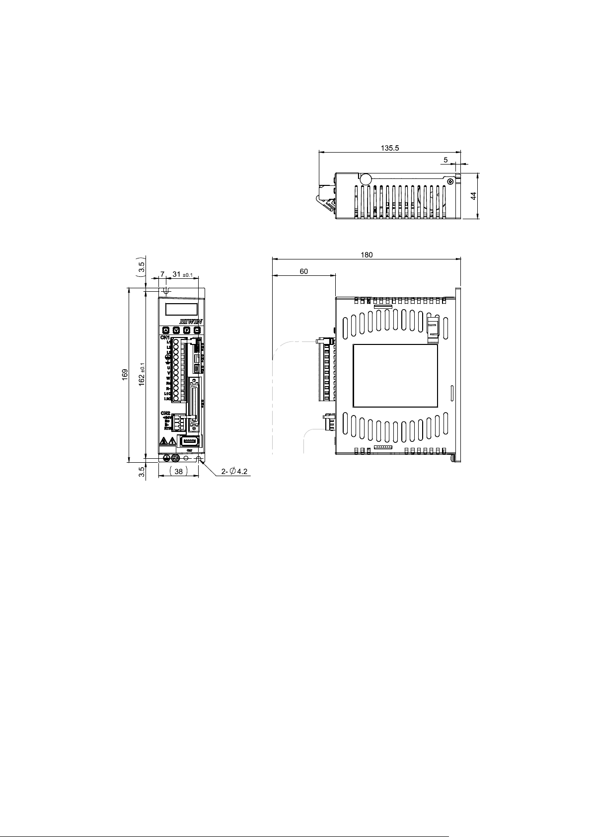
D2-DNN46A
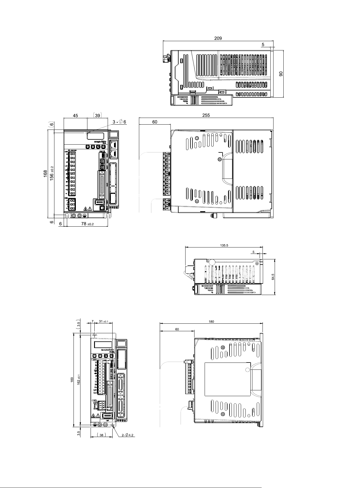
2.3. Drive dimensions
Dimensions and mounting holes of D2-series drives, D2-series drives with the EtherCAT
(CoE/ mega-ulink) module, and D2-series drives with the extension I/O module are shown in
the following figures. The dimension unit is in mm, and the diameter of mounting hole is 4 mm.
Fig. 2-3 Dimensions of frame A model
HIWIN Mikrosystem Corp. 14
D2 Drive User Guide v1.8 2. Specifications
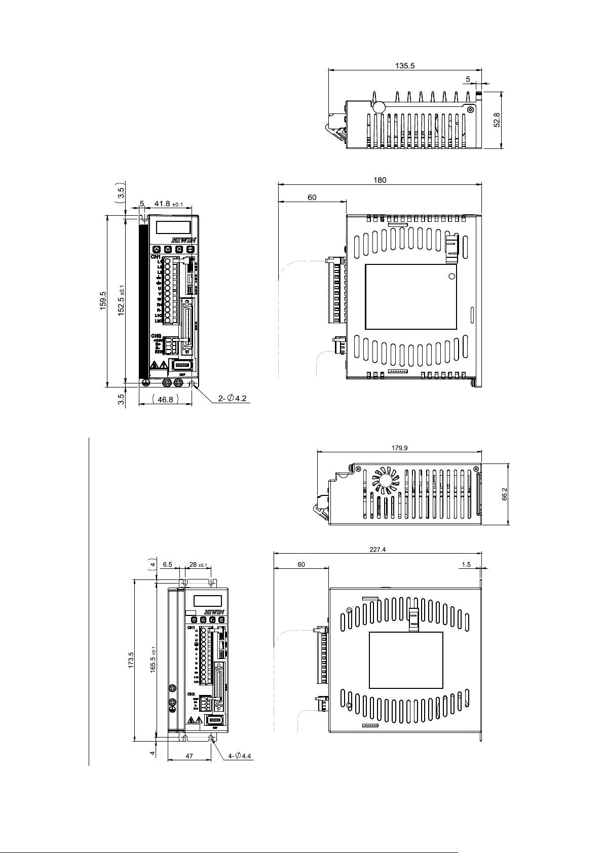
D2-DNN47A
D2-DNN48A
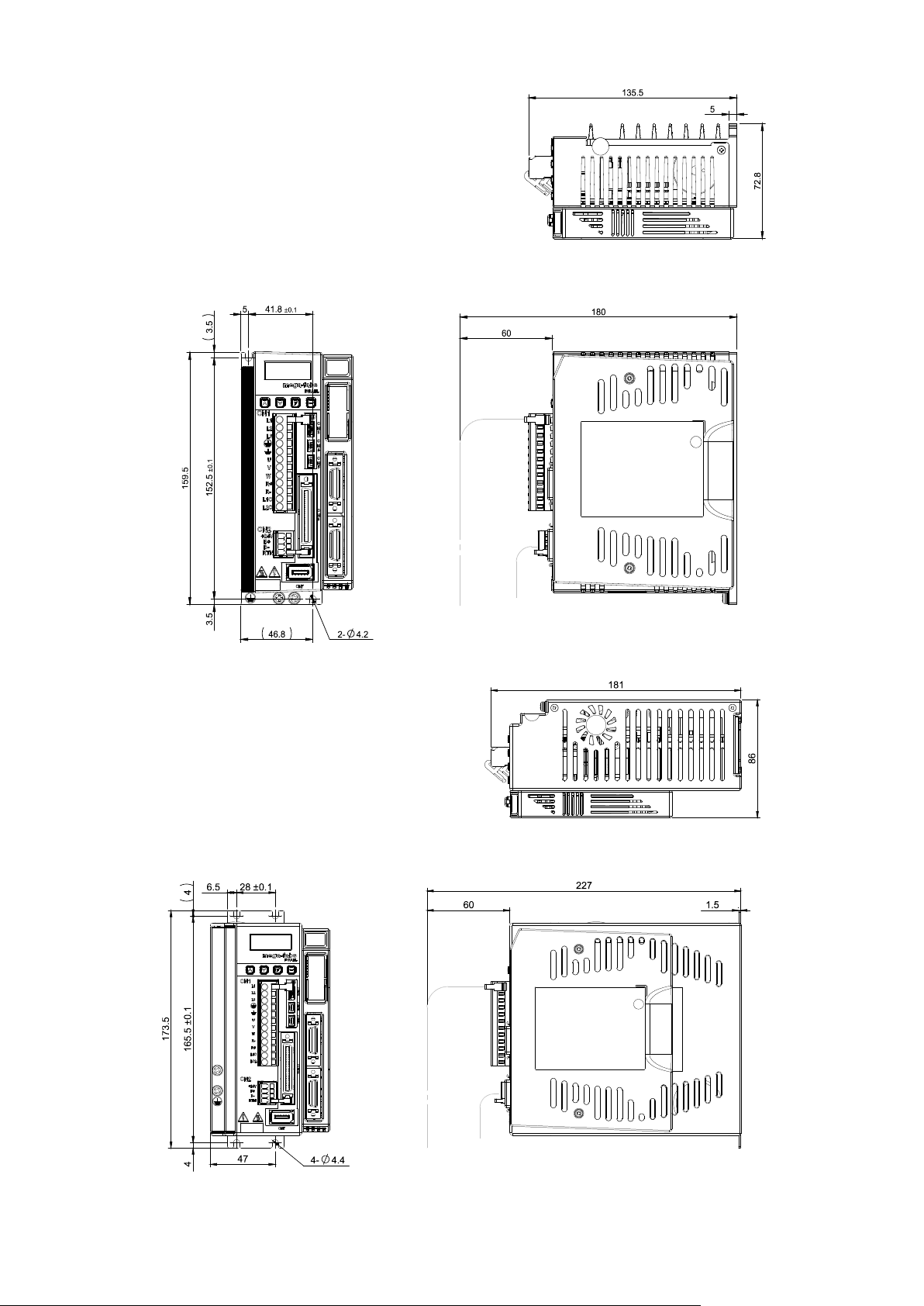
Fig. 2-4 Dimensions of frame B model
Fig. 2-5 Dimensions of frame C model
HIWIN Mikrosystem Corp. 15
D2 Drive User Guide v1.8 2. Specifications
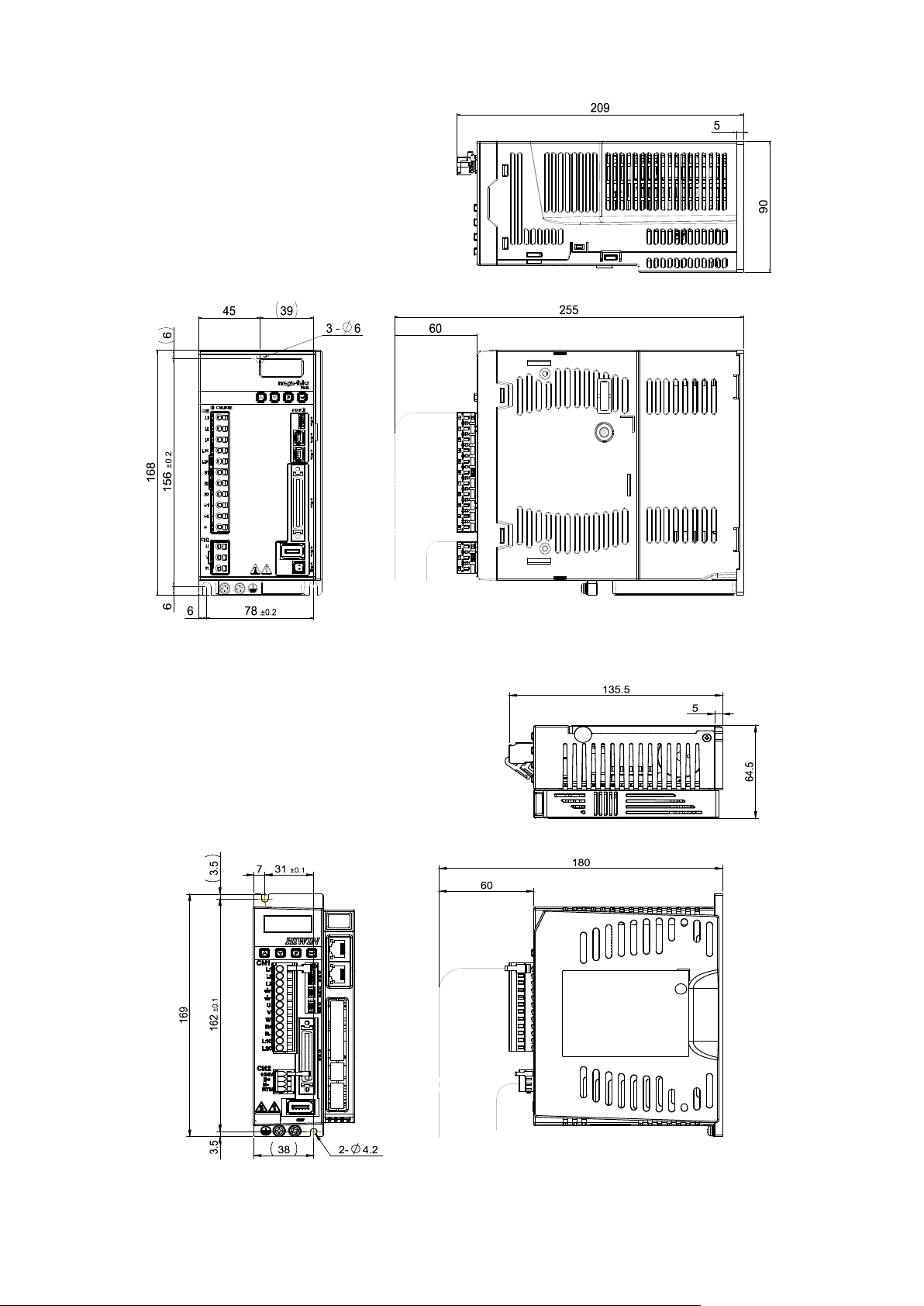
D2-DNN52A
D2-DNN43A
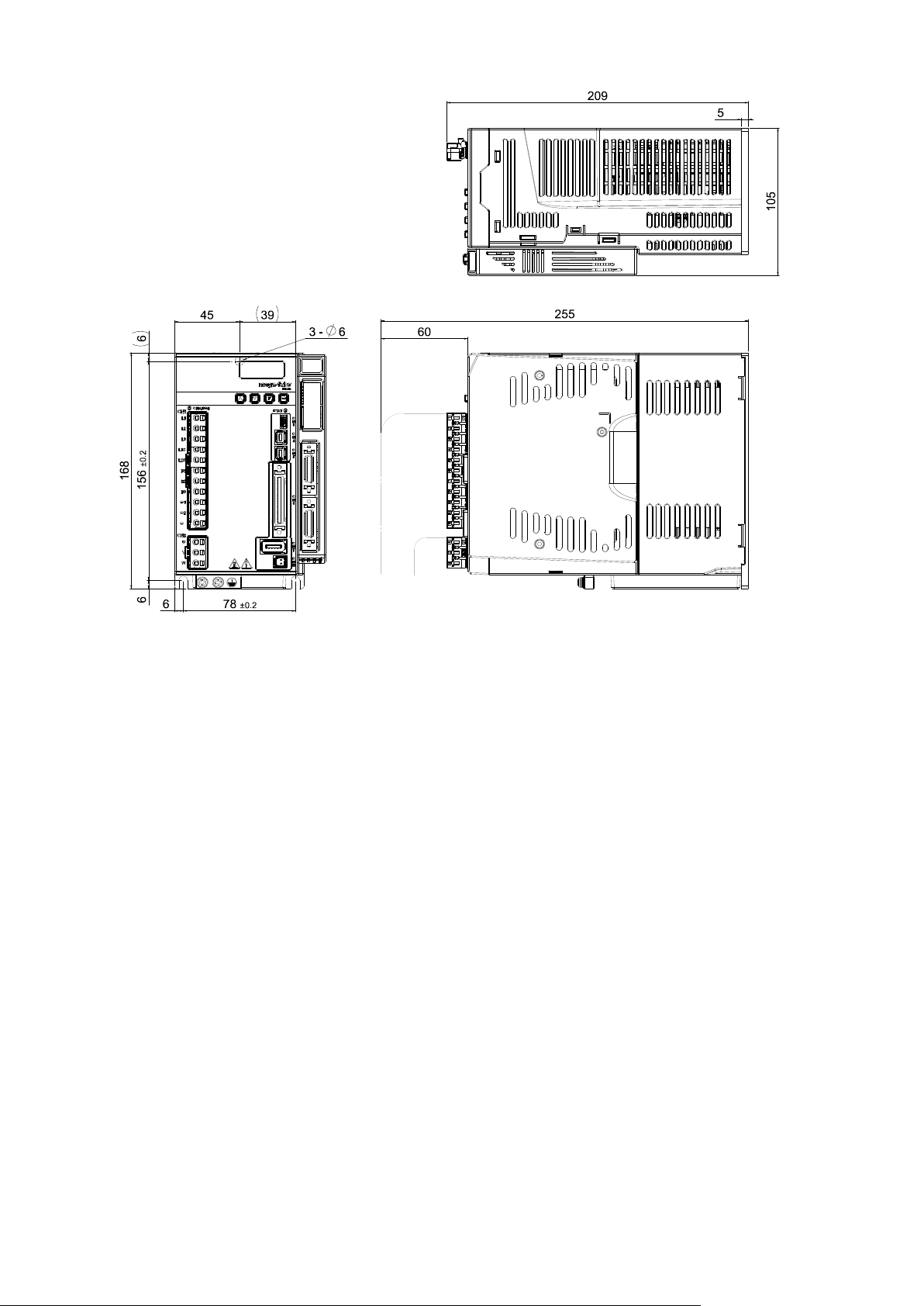
Fig. 2-6 Dimensions of frame D model
Fig. 2-7 Dimensions of frame A model with the EtherCAT module
HIWIN Mikrosystem Corp. 16
D2 Drive User Guide v1.8 2. Specifications
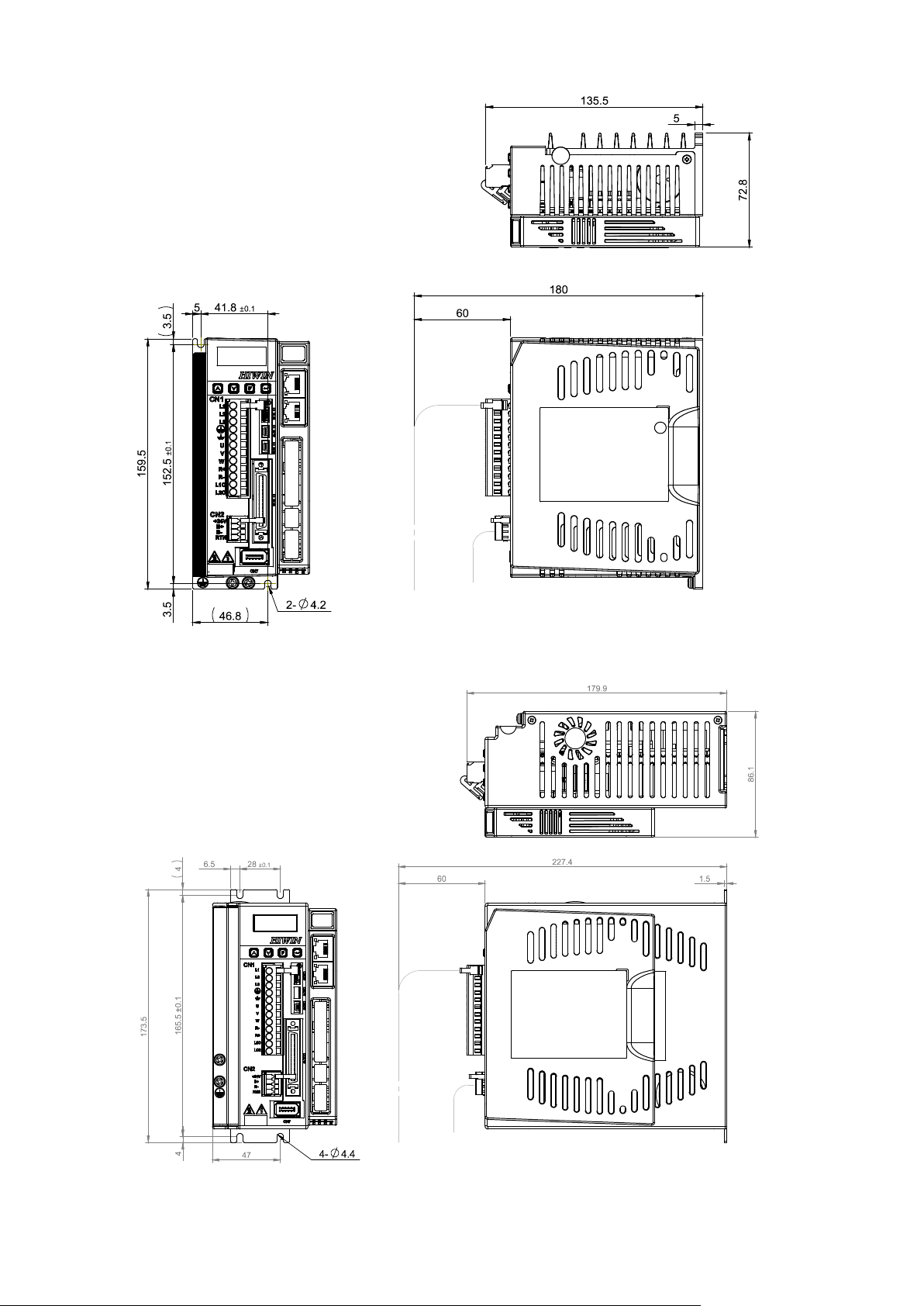
D2-DNN44A
D2-DNN45A
Fig. 2-8 Dimensions of frame B model with the EtherCAT module
Fig. 2-9 Dimensions of frame C model with the EtherCAT module
HIWIN Mikrosystem Corp. 17
D2 Drive User Guide v1.8 2. Specifications
D2-DNN57A
D2-DNN54A
Fig. 2-10 Dimensions of frame D model with the EtherCAT module
Fig. 2-11 Dimensions of frame A model with the extension I/O module
HIWIN Mikrosystem Corp. 18
D2 Drive User Guide v1.8 2. Specifications
D2-DNN55A
D2-DNN56A
Fig. 2-12 Dimensions of frame B model with the extension I/O module
Fig. 2-13 Dimensions of frame C model with the extension I/O module
HIWIN Mikrosystem Corp. 19
D2 Drive User Guide v1.8 2. Specifications
D2-DNN53A
Fig. 2-14 Dimensions of frame D model with the extension I/O module
HIWIN Mikrosystem Corp. 20
D2 Drive User Guide v1.8 2. Specifications
50 mm
or more
20 mm
or more
20 mm
or more
50 mm
or more
Electric
cabinet
50 mm
or more
50 mm
or more
2.4. Drive installation
To fix drive in the used environment (e.g. electric cabinet), conductive screws must be used to
secure drive to electric cabinet. Moreover, insulating materials (e.g. paint) on the contact
surface of electric cabinet must be removed, so that the drive can connect to ground through
the machine. If the main power of drive is 220 V, the grounding resistance must be less than
50 Ω; if 110 V, it must be less than 100 Ω.
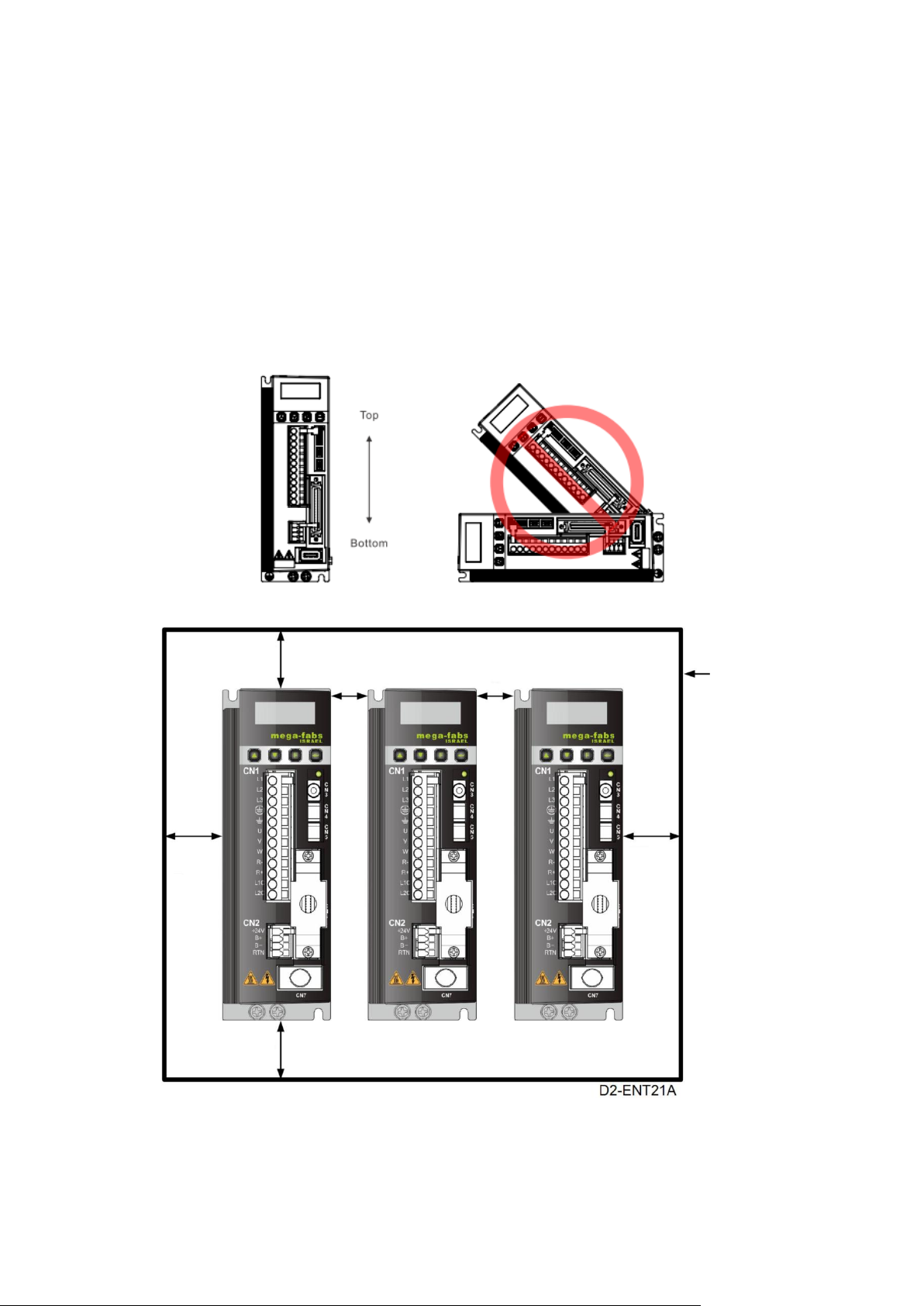
Installing drive must be careful, not to shut suction hole and vent, and not place it in the
inclined position. Otherwise, it will cause drive failure. In order to ensure that the effect of
cooling circulation is well, installing drive should keep an enough space between the drive and
the adjacent article or baffle. If more than one drive is installed, keep the space between
drives more than 20 mm, such that the drive has an enough space for heat dissipation. Fans
can be set in the electric cabinet to facilitate the heat dissipation of drives.
Fig. 2-15
Fig. 2-16 Space between drives
HIWIN Mikrosystem Corp. 21

D2 Drive User Guide v1.8 2. Specifications
CPU
1.0 GHz or more
RAM
512 MB or more
Available space on
the hard disk
50 MB or more
Communication port
USB
Operating system
Windows 2000, Windows XP, Windows 7
Screen resolution
1024 x 768 pixels or more
2.5. Computer requirements
Table 2-3
HIWIN Mikrosystem Corp. 22

D2 Drive User Guide v1.8 3. Operation Principles
3. Operation Principles
3. Operation Principles ....................................................................................................... 23
3.1. Operation modes .................................................................................................. 24
3.1.1.
3.1.2.
3.1.3.
3.1.4.
3.2. Encoder type ........................................................................................................ 26
3.3. Encoder signal output ........................................................................................... 27
3.4. Path planning ....................................................................................................... 28
3.5. Servo loops and gains .......................................................................................... 30
3.6. Gain margin and phase margin ............................................................................ 31
3.6.1.
3.6.2.
3.7. Move and settling ................................................................................................. 34
3.8. Error compensation .............................................................................................. 35
3.9. Velocity ripple ....................................................................................................... 36
3.10. Enable .................................................................................................................. 37
3.11. Common physical quantities ................................................................................. 38
Position mode ............................................................................................. 24
Velocity mode ............................................................................................. 24
Force/torque mode ..................................................................................... 25
Stand-alone mode ...................................................................................... 25
Nyquist diagram .......................................................................................... 31
Bode diagram ............................................................................................. 32
HIWIN Mikrosystem Corp. 23
D2 Drive User Guide v1.8 3. Operation Principles
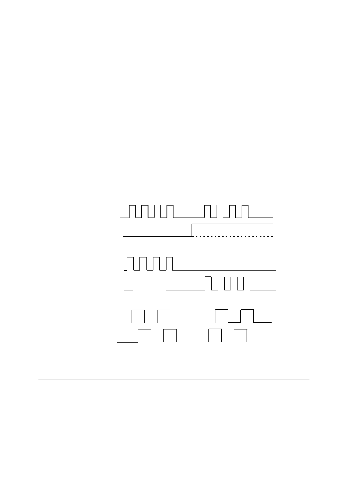
Pulse input
Dir input
A-phase input
B-phase input
CCW input
CW input
Reversal
Forward
Forward
Forward
Reversal
Reversal
3.1. Operation modes
The following operation modes can be used to implement the interface between the standard
D2 drive and the host controller.
(1) Position mode;
(2) Velocity mode;
(3) Force/torque mode;
(4) Stand-alone mode.
Each mode is described as follows.
3.1.1. Position mode
The host controller sends pulses to drive. These pulses are equal to position commands.
When the drive receives a pulse, it moves the motor with a corresponding distance. The host
controller is responsible for path planning. The pulse is sent faster and faster at the
acceleration, and is sent with a fixed frequency at the constant speed. As shown in Fig. 3-1,
there are three formats of pulse signal: pulse/direction (pulse/dir), pulse up/pulse down
(CW/CCW), and quadrature (AqB). Based on the hardware wiring, the pulse signal can be
classified into the differential and single-end TTL logic signals.
The electronic gear can be set in the position mode. One input pulse is normally set to be
equal to one encoder count. For example, the gear ratio of 2:3 means that 2 input pulses is
equal to 3 encoder counts.
Fig. 3-1
3.1.2. Velocity mode
The drive can receive the command from the host controller via voltage, so as called V
command. The input voltage range is from -10 V to +10 V. The drive converts the received
external voltage to the corresponding velocity command to drive the motor. Besides the
voltage, the host controller can also send the velocity command via PWM signal, so as called
PWM command. It utilizes different duty cycles to correspond to different velocity commands.
There are two types of PWM command: single-line type (PWM 50%) and dual-line type (PWM
100%). The single-line type (PWM 50%) takes the duty cycle of 50% as the basis. If the duty
cycle of PWM command is less than 50%, the motor performs the reverse motion; while if
greater than 50%, the motor performs the forward motion. In addition to using one pin to
transmit PWM command, the dual-line type (PWM 100%) needs another pin to control motion
HIWIN Mikrosystem Corp. 24

D2 Drive User Guide v1.8 3. Operation Principles
direction.
(1) Use voltage command
The drive converts the analog voltage to the velocity command to control the speed of
motor movement. The higher the voltage is, the faster the output speed is. However, the
maximum output speed is limited by the maximum motor speed. The lower the voltage is,
the slower the output speed is. When the voltage value is negative, the output speed is
negative and the motor moves in the reverse direction. The drive can set the command
speed corresponding to the voltage per unit.
(2) Use PWM command
The drive converts the PWM signal to the velocity command to control the speed of motor
movement. It can set the command speed corresponding to “Full PWM”.
3.1.3. Force/torque mode
In the force/torque mode, the command from the host controller, which can be received by the
drive, is the same as that in the velocity mode. There are V command and PWM command.
After the drive receives these two commands, it converts them to the corresponding current to
drive the motor.
(1) Use voltage command
The drive converts the analog voltage to the current command. By controlling the output
current of drive, it can control the force or torque of motor movement. The higher the
voltage is, the larger the output current is. However, the maximum output current is limited
by the maximum motor current. The lower the voltage is, the smaller the output current is.
When the voltage value is negative, the output current is negative and the motor moves in
the reverse direction. The drive can set the command current corresponding to the
voltage per unit.
(2) Use PWM command
The drive converts the PWM signal to the current command to control the force or torque
of motor movement. It can set the command current correspond to “Full PWM”.
3.1.4. Stand-alone mode
There is one high-speed DSP on the inside of drive. Therefore, the drive can plan the motion
profile by itself. If the drive needs to do test alone or without any host controller (e.g. only the
servo motor and drive), the stand-alone mode can be selected to let drive be responsible for
all control loops.
HIWIN Mikrosystem Corp. 25

D2 Drive User Guide v1.8 3. Operation Principles
Resolution
Grating Period
3.2. Encoder type
The encoder usually plays an important role in the servo motor control. It provides the
information of drive position or angle to realize the servo-loop control. There are two types of
commonly used encoder: digital type and analog type. D2-series drives only support the
digital encoder presently, but not analog encoder.
(1) Digital type
The digital or so-called incremental encoder normally outputs the differential signal of TTL
RS422. The main feature of this signal is two digital pulses with the 90°-phase difference.
The definition of resolution for this signal is given in Fig. 3-2
(2) Analog type
The analog encoder has two-phase signals: sin and cos. The hardware normally takes
the differential signal of 1 Vpp. The main feature of this signal is two sinusoidal signals
with the 90°-phase difference. Its specification is normally represented by the grating
period. For example, the grating period of common linear analog scale is 40 um.
Fig. 3-2
Fig. 3-3
HIWIN Mikrosystem Corp. 26

D2 Drive User Guide v1.8 3. Operation Principles
Encoder
D2
Switchable
Signal
Processing
Emulated
Output
Buffered
3.3. Encoder signal output
The input signal of encoder is used to perform the servo control by the servo drive. When the
drive works with the host controller, the host controller also has the requirement of receiving
position signal. Normally, the drive will transmit the position or angle signal received from the
encoder to the host controller. D2 drive provides the following two modes of encoder output.
(1) Buffered encoder output
When this mode is selected, the drive sends the received encoder signal to the host
controller directly. Besides, if the invert of encoder signal is required, check the option of
invert function. At this time, the drive inverts the received encoder signal and sends it out.
(2) Emulated encoder output
When this mode is selected, the drive multiplies the received encoder position by a scale
and sends it out to the host controller. For some cases, if the host controller cannot
receive the encoder signal with a too high frequency, the scale can be set to lower the
frequency of encoder output. In addition, if the multiplier factor of analog encoder is set
too high, the scale can also be set to lower the resolution of encoder output.
Encoder
Output
Encoder
Fig. 3-4
HIWIN Mikrosystem Corp. 27

D2 Drive User Guide v1.8 3. Operation Principles
Time (t)
Position (p)
Velocity (v)
Acceleration (a)
3.4. Path planning
The main purpose of path planning is that the host controller calculates the suitable motion
command based on the user’s actual requirement of distance, velocity, acceleration, and
smooth factor, as shown in Fig. 3-5. This command (pulse or V command) is sent to the drive
by the host controller, or calculated by the drive itself (stand-alone mode). Different
configurations are adopted according to different applications.
Fig. 3-5
(1) Position
The encoder provides the position information of motor to the drive, such that the drive
can realize the current motor position. For the linear motion, common position units are
um, mm, and m; while for rotary motion, it is the encoder count. For D2 drive, “Reference
position” denotes the position command, which is calculated by the path generator based
on the related parameters. However, “Target position” is the target position set by the
user or host controller. After this parameter is sent to the drive, normally, it needs to be
calculated by the path generator so as to let motor move.
(2) Velocity
The velocity is defined as the difference of position per unit time. For linear motion,
velocity units are um/sec, mm/sec, m/sec; while for rotary motion, they are count/sec, rps,
and rpm.
(3) Acceleration
The acceleration is defined as the difference of velocity per unit time. For linear motion,
acceleration units are um/sec2, mm/sec2, and m/sec2; while for rotary motion, it is rps2.
(4) Smooth factor
When the acceleration is rapidly increased or decreased in a short time, it means that the
force applied to moving object is suddenly increased or decreased. Sometimes, to reduce
such impact, the technique of smooth motion is introduced to the motion control loop, so
as to enhance the performance. D2-serise drives adopt the technique of smooth factor to
achieve this effect. By using the smooth factor, the motion trajectory can be planned to
S-type or T-type curve. Its value can be set from 0 to 500. If this value is larger, the
trajectory is closer to S-Type curve and the impact is smaller. On the other hand, if this
value is smaller, the trajectory is closer to T-Type curve. As this value being 1, it means
that there is no effect of smooth function. When the value of smooth factor is increased, in
some case, the settling performance during positioning process will be enhanced, since
the impact of motor force is reduced. However, when the motion becomes smoother, the
move time of path planning is unavoidably increased. Tests on the practical machine are
needed to adjust the smooth factor, so as to get the balance between them. As the
smooth factor is set to 0, the motion protection of drive is disable.
HIWIN Mikrosystem Corp. 28

D2 Drive User Guide v1.8 3. Operation Principles
(5) Emergency stop
D2-series drives have the function of emergency stop. When the drive deactivates the
signal of “Axis enable” on the pin I3, this function is activated. At this moment, the drive
immediately stops the motor in any motion by using the deceleration for emergency stop
to guarantee safety.
HIWIN Mikrosystem Corp. 29

D2 Drive User Guide v1.8 3. Operation Principles
Common
Gain
Position
Loop
Velocity
Loop
Filter
Current
Loop
Filter
Motor &
Encoder
Actual Current
Feedback Velocity
Feedback Position
Target
Position
Reference
Position
Reference
Velocity
Command
Current
PWM
Output
0.1
……………………………………5……………………………………
1
Control rigidity
Response
High
Low
3.5. Servo loops and gains
(1) Servo loops
There are three types of control loop for D2 drive: current, velocity, and position control
loops to implement the servo motor control. The architecture of drive’s servo loop is
described in Fig. 3-6. In the position mode, three loops should be connected in sequence
to perform the position control for the motor. In the velocity mode, the velocity loop should
use the current loop to drive the motor. However, in the current mode, the current loop
only controls the phase commutation mechanism of motor, and its command is controlled
by the voltage command from the host controller. To simplify gain parameters of servo
loops, D2 drive only uses one common gain (CG) to set and adjust the overall
control-loop architecture.
Fig. 3-6
(2) Servo gains
D2 drive uses one high-speed DSP to implement the motor control. Generally, when the
servo loop is implemented by the digital method, it needs to adjust many servo gains.
However, this drive adopts an ingenious control design to simplify servo gains as one
common gain to significantly improve convenience.
Fig. 3-7
HIWIN Mikrosystem Corp. 30

D2 Drive User Guide v1.8 3. Operation Principles
)
( p j
G
0
p
G
Re
G
j
Im
Plane
j
G
Phase crossover
0
)(log
)(
log
p
p
jG
jG
1010
20
1
20
3.6. Gain margin and phase margin
3.6.1. Nyquist diagram
Gain margin (GM) is defined as that the loop gain, calculated by dB, can be increased before
the close-loop system becomes unstable. On the other hand, phase margin (PM) is defined as
that the phase delay can be increased before the close-loop system becomes unstable.
(1) Gain margin:
Denote G(jωp) as the relative distance from the intersection of Nyquist diagram and the
negative real axis to the point (-1, j0), where ωp is the frequency at the phase crossover.
The example of G(jωp) = 180° is shown in Fig. 3-8. For the transfer function G(s) in a
loop system,
gain margin = GM = dB.
Following results can be derived from Fig. 3-8 and characteristics of Nyquist diagram.
a. If G(jω) does not intersect with the negative real axis, |G(jωp)| = 0 and GM = dB.
When the Nyquist diagram does not intersect with the negative real axis at any
non-zero and finite frequency, GM = dB. Theoretically, the loop gain can be
increased to be infinite before the system becomes unstable.
b. If G(jω) intersects with the negative real axis between 0 and -1, 0 < |G(jωp)| < 1 and
GM > 0 dB. When the Nyquist diagram intersects with the negative real axis between
0 and -1 at any frequency, the system is stable as increasing loop gain.
c. If G(jω) is at the point (-1, j0), |G(jωp)| = 1 and GM = 0 dB. When the Nyquist diagram
G(jω) is at the point (-1, j0), GM = 0 dB. This means that the system reaches the
unstable boundary and the loop gain cannot be increased any more.
d. If G(jω) passes by the point (-1, j0), |G(jωp)| > 1 and GM < 0 dB. When the Nyquist
diagram G(jω) passes by the point (-1, j0), GM < 0 dB. At this time, GM must be
reduced to achieve the steady state of loop gain.
HIWIN Mikrosystem Corp. 31
Fig. 3-8 Gain margin of Nyquist diagram

D2 Drive User Guide v1.8 3. Operation Principles
40
20 0 -20
-40
-60
-360
0
-90
-180
-270
Gain crossover
gp
Phase crossover
Gain margin
Phase
margin
)()( dBjG
(deg)
)
( j G
sec)
/ ( rad
sec)
/ ( rad
0
g
G
Re G j
Im
Plane
j
G
Gain
crossover
0
1
-1
Phase margin
(2) Phase margin
Phase margin is defined as that the angle between the straight line passing through the
gain crossover and the negative real axis of G(jω)-plane, as shown in Fig. 3-9.
Phase margin = PM = G(jωg) -180°.
Fig. 3-9 Phase margin of Nyquist diagram
3.6.2. Bode diagram
The gain margin and phase margin of Bode diagram are given in Fig. 3-10.
Fig. 3-10 Gain margin and phase margin of Bode diagram
HIWIN Mikrosystem Corp. 32

D2 Drive User Guide v1.8 3. Operation Principles
0 dB
-3 dB
Bandwidth
Gain (dB)
f
The bandwidth of Bode diagram is defined as the frequency at -3 dB, as shown in Fig. 3-11.
Fig. 3-11 Bandwidth of Bode diagram
HIWIN Mikrosystem Corp. 33

D2 Drive User Guide v1.8 3. Operation Principles
Total time
Move time
Settling time
T
Position
- target radius
Reference
Feedback position
Position
Time
After entering the radius
“In-position” signal.
3.7. Move and settling
The motor moves based on the path planned by the host controller. When it arrives at the
target position, it is able to position accurately and stop motion. This is called move and
settling.
(1) Position error
In the servo system, there is a certain difference between the target position and the
encoder feedback position. This is called position error.
(2) Target radius
After the motor arrives at the target position, the difference between the feedback position
and the target position must be controlled and kept within a specific positive/negative
small range. This range is called target radius.
(3) Total time of move and settling
As shown in Fig. 3-12, after the motor arrives at the target position, the position error
should be smaller than the setting of target radius and keep for a certain time (debounce
time). After that, the “In-position” signal is set and called in position. If the position error is
continuously out the radius, it is called not yet in position. The total time spent from the
motion start to the settling achievement is the amount of move time and settling time.
position
arget
for a debounce time,
send out the
Fig. 3-12
HIWIN Mikrosystem Corp. 34

D2 Drive User Guide v1.8 3. Operation Principles
drive
Host Controller
Feedback position
input from encoder
Error map
Motor cable
Feedback
position output
Pulse command
input
Mapping effective area
+ position
+ position
index
Mapping effective area
Home offset
= 100
Drive coordinate = 0
Drive coordinate = -100
index
Drive coordinate = 0
3.8. Error compensation
Normally, the positioning accuracy of drive is determined by the performance of encoder. But
sometimes, the encoder cannot completely meet the requirement of accuracy. In this case,
instruments with the higher level of accuracy (e.g. laser interferometer) should be applied to
measure the system error. D2 drive has one high-performance control method. It saves the
measured error data into the error map of drive, as shown in Fig. 3-13, and uses this data
during motion. By adopting the method of linear interpolation between the fixed distance, it
calculates the value of error compensation to enhance the positioning accuracy.
Motor D2
Fig. 3-13
The mapping effective area is determined by the index signal. The area from the index
towards positive direction is the mapping effective area; while the area from the index towards
negative direction is the area without mapping. As shown in the following figure, the mapping
effective area for non-zero home offset is the same as that for zero home offset.
A. Home offset = 0
B. Home offset = 100
HIWIN Mikrosystem Corp. 35
Fig. 3-14

D2 Drive User Guide v1.8 3. Operation Principles
%,RippleVelocity 100
2
1
V
VV
target
minmax
(a)
(b)
Constant
Velocity
Constant
Velocity
V
V
V
target
V
V
target
V
3.9. Velocity ripple
Generally in the motion control, it is always desirable that the motion in the constant-speed
phase is as smooth as possible. The motion stability can be estimated by the index of velocity
ripple. Main factors causing the variation in the constant-speed phase are the motor cogging
force, cable chain, air pipeline, and guideway friction, and so on. This velocity ripple is usually
used for scanning or detecting machines required high stability in the constant-speed phase.
The equation of velocity ripple is:
where V
and V
is the target velocity, V
target
is the minimum velocity in the constant-speed phase. As shown in Fig. 3-15, the
min
is the maximum velocity in the constant-speed phase,
max
velocity ripple of (a) is larger indicated less steadiness; while (b) is smaller indicated better
steadiness.
Fig. 3-15
HIWIN Mikrosystem Corp. 36

D2 Drive User Guide v1.8 3. Operation Principles
3.10. Enable
The enable is a necessary step before the drive starts to receive any motion command. Only
at the enable state, the drive can receive the pulse or voltage command from the host
controller to do motion.
(1) Step motion mode
The step motion (SM) mode is an open-loop architecture. At this mode, the motor
behavior is similar as the stepper motor. The signal of feedback position is not adopted at
the enable. This mode is used to ensure that the force direction of motor is consistent with
the direction of encoder feedback. If not, it will cause the failure of phase initialization.
(2) Phase initialization
For the drive with the incremental encoder, it needs to find the electrical angle at the first
power-on, called phase initialization. For HIWIN servo motors, after the drive is booted, it
is able to successfully find the electrical angle almost without any movement at the first
enable process. The other common method of phase initialization is to add Hall sensor to
achieve the same effect. Generally, the host controller sends an output signal to the drive
(e.g. the input I3 of D2 drive) to complete the phase initialization and enable process.
HIWIN Mikrosystem Corp. 37

D2 Drive User Guide v1.8 3. Operation Principles
No.
Physical quantities
Description
1
Feedback Position
Feedback position
2
Reference Position
Position command
3
Target Position
Target position
4
Position Error
Position error
5
Single turn feedback position
Feedback position of single-turn encoder (only for the
drive supporting single-turn encoder)
6
Dual loop feedback position
Feedback position of dual-loop encoder (only for the
drive supporting dual-loop control)
10
Feedback Velocity
Feedback velocity
11
Reference Velocity
Velocity command
12
Velocity Error
Velocity error
20
Reference Acceleration
Acceleration command
30
Actual Current
Actual current
31
Command Current
Current command
32
Current effective value
Effective value of current during calculation period
40
Analog Command
Voltage command (from the host controller)
41
Bus Voltage
Line voltage
42
Servo Voltage Percentage
Servo voltage
45
PWM Command
Torque/force/velocity command (from host controller)
51
Soft-Thermal Accumulator
Temperature estimation via software
53
Average load ratio
Average load ratio during calculation period
54
Peak load ratio
Peak load ratio during calculation period
61
I1
Input 1
62
I2
Input 2
63
I3
Input 3
64
I4
Input 4
65
I5
Input 5
66
I6
Input 6
71
I7
Input 7
72
I8
Input 8
67
I9
Input 9
68
I10
Input 10 (only for D2T model)
81
O1
Output 1
82
O2
Output 2
83
O3
Output 3
84
O4
Output 4
86
O5
Output 5 (only for D2T model)
85
CN2/BRK
Brake signal output
3.11. Common physical quantities
Table 3-1
HIWIN Mikrosystem Corp. 38

D2 Drive User Guide v1.8 4. Wiring
4. Wiring
4. Wiring ............................................................................................................................. 39
4.1. System configuration and wiring ........................................................................... 40
4.1.1.
4.1.2.
4.1.3.
4.1.4.
4.1.5.
4.1.6.
4.1.7.
4.1.8.
4.1.9.
4.1.10.
4.2. Drive accessories ................................................................................................. 54
4.3. Main power wiring ................................................................................................ 58
4.3.1.
4.3.2.
4.4. Multiple drives connection .................................................................................... 60
4.5. I/O signal wiring .................................................................................................... 62
4.5.1.
4.5.2.
4.6. Wiring examples for control commands ................................................................ 65
4.6.1.
4.6.2.
4.6.3.
System wiring diagram ............................................................................... 40
CN1 power ................................................................................................. 43
CN2 brake/motor power .............................................................................. 47
CN3 USB communication ........................................................................... 48
CN4 Modbus communication ...................................................................... 48
CN5 Modbus communication/safety function .............................................. 49
CN6 control signal ...................................................................................... 50
CN7 encoder .............................................................................................. 52
CN8 EtherCAT communication ................................................................... 52
CN13/CN14 extension I/O signal ................................................................ 53
AC power wiring (single-phase) .................................................................. 58
AC power wiring (three-phase) ................................................................... 59
Digital input wiring....................................................................................... 62
Digital output wiring .................................................................................... 63
System wiring diagram for pulse command................................................. 65
System wiring voltage for analog command ................................................ 73
System wiring diagram for PWM command ................................................ 75
HIWIN Mikrosystem Corp. 39

D2 Drive User Guide v1.8 4. Wiring
4.1. System configuration and wiring
This chapter describes the system configuration of drive and the function of each connector.
4.1.1. System wiring diagram
The following figure shows the name, function, and specification of each drive connector .
Fig. 4-1
HIWIN Mikrosystem Corp. 40

D2 Drive User Guide v1.8 4. Wiring
(b) Extension I/O module
CN8-out
CN8-in
CN13
CN14
(a) EtherCAT module
Fig. 4-2
Fig. 4-3
HIWIN Mikrosystem Corp. 41

D2 Drive User Guide v1.8 4. Wiring
Item
no.
Name
Connector
Description
1
AC main power
cable
Frame A-D: CN1
L1, L2: Single-phase 200-240 Vac, 50/60Hz
L1, L2, L3: Three-phase 200-240 Vac, 50/60Hz
(The frame D model is only allowed connecting to
three-phase AC power)
2
Motor power
cable
Frame A-C: CN1
( , U, V, W)
Frame D: CN2 (U, V, W)
Connected to motor, three-phase motor power
3
Regenerative
resistor
Frame A-C: CN1 (R-, R+)
Frame D: CN1 (B1, B2, B3)
Connected to regenerative resistor
(optional/installed according to actual application)
4
Control power
cable
Frame A-D: CN1
(L1C, L2C)
Drive control and I/O power
(L1C, L2C: Single-phase 200-240 Vac, 50/60Hz)
5
Brake
Frame A-C: CN2 (B-, B+)
Frame D: CN6 (O5-, O5+)
Connected to brake
(optional/installed according to actual application)
6
Mini USB
communication
Frame A-D: CN3
Connected to PC (for parameter setting; to be
removed after setting)
Using mini USB to connect with PC for monitoring
drive, doing test runs, or writing parameters, etc.
7
Modbus
communication
Frame A-C: CN4, CN5
Frame D: CN4
Connected to host controller by using Modbus
communication protocol
8
Control signal
Frame A-D: CN6
Connected to host controller
9
Feedback
signal
Frame A-D: CN7
Connected to motor encoder
10
EtherCAT
communication
Frame A-D: CN8
Connected to host controller by using EtherCAT
communication protocol
11
Extension I/O
signal
Frame A-D: CN13, CN14
Extension I/O module
12
Safety function
signal
Frame D: CN5
Connected to safety device
13
DC reactor
Frame D: CN1
Connected to DC reactor
(optional/installed according to actual application)
14 Frame D: CN15
Reserved
Table 4-1
HIWIN Mikrosystem Corp. 42

D2 Drive User Guide v1.8 4. Wiring
Signal
Function
1
L1
AC main power, 220 Vac (50/60 Hz) single/three phase
2
L2
AC main power, 220 Vac (50/60 Hz) single/three phase
3
L3
AC main power, 220 Vac (50/60 Hz) three phase
4
Ground input of AC main power
5
Motor ground input
6
U
Motor U-phase input
7
V
Motor V-phase input
8
W
Motor W-phase input
9
REG-
Negative terminal of regenerative resistor
10
REG+
Positive terminal of regenerative resistor
11
L1C
Control power, 220 Vac (50/60 Hz) single phase
12
L2C
4.1.2. CN1 power
The pin assignment of CN1 for frame A-C models is different with that for the frame D model.
Check the pin assignment for each model before use. Descriptions of CN1 power wiring
include: single/three-phase power input, motor power output (frame A-C), regenerative
resistor wiring, single-phase control power input, and DC reactor wiring (frame D).
4.1.2.1. Power wiring
Before connecting the main circuit of drive, ensure that the drive is properly grounded. Frame
D model is only allowed connecting three-phase 200 - 240 Vac.
(1) Frame A-C
Connector model: Wago 721-112/026-000 (female).
Fig. 4-4 CN1 connector type for frame A-C models
Fig. 4-5 Installation and removal methods
Table 4-2
HIWIN Mikrosystem Corp. 43

D2 Drive User Guide v1.8 4. Wiring
Signal
Function
1
L1
AC main power, 220 Vac (50/60 Hz) three phase
2
L2
3
L3 4 L1C
Control power, 220 Vac (50/60Hz) single phase
5
L2C 6 B1
Regenerative resistor input
7
B2
Regenerative resistor input
8
B3
Regenerative resistor input
9
○
-
1
DC reactor input
10
○
-
2
DC reactor input
11
○
-
DC reactor input
Motor
mega-fabs
D2 Series drive
CN1
L1
L2
L3
U
V
W
REGREG+
L1C
L2C
(2) Frame D
Connector model: TE Connectivity 1-2229794-1 (female).
The ground wire of main power should be connected to the drive housing.
Fig. 4-6 CN1 connector type for frame D model
Table 4-3
4.1.2.2. Motor wiring
Be sure to ground the drive and the motor. The following motor wiring is only suitable for
frame A-C models.
HIWIN Mikrosystem Corp. 44
Fig. 4-7

D2 Drive User Guide v1.8 4. Wiring
Fuse
Regenerative
resistor case
mega-fabs
D2 Series drive
CN1
L1
L2
L3
U
V
W
REGREG+
L1C
L2C
(a) Using internal regenerative
resistor (13 Ω/100 W)
(b) Using external regenerative resistor
Fuse
D2T 2KW
series drive
Regenerative
resistor case
D2T 2KW
series drive
4.1.2.3. Regenerative resistor wiring
The regenerative resistor is optional. However, the frame D model has one internal
regenerative resistor (13 Ω/100 W). Install it according to the actual application.
(1) Frame A-C
(2) Frame D
Fig. 4-8
4.1.2.4. DC reactor wiring
The DC reactor is optional. Its main function is to improve the input power factor and suppress
the harmonic current. Only the frame D model supports this feature. Install it according to the
actual application.
HIWIN Mikrosystem Corp. 45
Fig. 4-9

D2 Drive User Guide v1.8 4. Wiring
Caution
● Wiring and the related inspection must be done by the professional technician.
● Turn off the power before wiring or inspection to avoid electric shock and other
dangers.
● After the power is turned off, do not touch power terminals for a short time
period (at least 5 minutes), since the power in the drive remains high.
● Perform wiring correctly and reliably; otherwise it may cause uncontrolled motor
operation, personnel injury, machine malfunction, or other unexpected
accidents.
● Do not connect the U, V, or W terminal of motor to power supply.
● Connectors of power and motor cables should be connected securely; otherwise
it may cause fire.
● Ensure that the drive and motor are grounded properly.
● The drive and motor should be installed before wiring; otherwise it may cause
electric shock.
● Do not damage, pull, or squeeze the wire; otherwise it may cause electric shock.
● The drive may interfere with the nearby electronic equipment. A noise filter could
be used to reduce the effect of electromagnetic interference.
● Do not make any modification to the drive.
● Do not put the main circuit cable, I/O signal cable, or encoder cable in the same
duct, or tie them together. The cable should be kept more than 30 cm away from
each other at wiring.
● Following instructions must be observed for wiring main circuit terminals:
※ Do not insert more than two wires in the same socket.
※ Check that there is no short circuit between the wire and its adjacent wire after
inserting the wire.
※ Use the specific power voltage; otherwise it may cause fire or drive damage.
● If the drive is used at the condition of poor or significantly fluctuating power,
ensure that the power is supplied within the specified range of voltage
fluctuation; otherwise it may cause drive damage.
● Install safety devices, such as breaker, to prevent the short circuit of external
wiring from damaging the drive.
● The appropriate isolation and shielding measures must be adopted when the
drive is used in the following environments; otherwise it may cause the poor
operation of drive.
※ Environment with the interference generated by the static electricity or the like.
※ Environment with a strong electric field or a strong magnetic field.
※ Environment with the emitted radiation.
HIWIN Mikrosystem Corp. 46

D2 Drive User Guide v1.8 4. Wiring
Single
Function
1
U
Motor U-phase input
2
V
Motor V-phase input
3
W
Motor W-phase input
Isolated
control power
Power:
4.1.3. CN2 brake/motor power
For frame A-C models, CN2 is the brake connector; while for the frame D model, CN2 is the
motor power connector. Check the pin assignment for each model before use. It is suggested
that the brake power should be independent power and does not use the same power source
with other power.
(1) Frame A-C
Use the brake wiring with a relay to connect the drive power of 24 Vdc to the brake.
Connector model: WAGO 734-104.
Fig. 4-10
Fig. 4-11 Brake wiring with a relay.
(2) Frame D
The motor ground wire should be connected to the drive housing.
Connector model: TE Connectivity 3-2229794-1 (female).
HIWIN Mikrosystem Corp. 47
Fig. 4-12
Table 4-4

D2 Drive User Guide v1.8 4. Wiring
mega-fabs
D2 Series drive
CN3
USB_D+
GND
USB_D-
+5V
3
5
2
1
GND
USB_D+
USB_D-
USB_VBUS
N/C
3
5
2
1
4
PC
USB
Serial
port
(a) RS485 (female connector)
(b) RS485 (male connector)
4.1.4. CN3 USB communication
Use the mini USB to connect with PC for monitoring drive, doing test runs, or writing
parameters, and so on. The corresponding operation please refers to Section 5.
Wiring diagram of mini USB communication
Use HIWIN cable with the shielding network. Its model is “USB 2.0 Type A to mini-B 5-pin
(1.8M)”.
Fig. 4-13
4.1.5. CN4 Modbus communication
Use RS485 cable to connect with the host controller. By using the Modbus serial
communication protocol, it can read and write drive parameters. All CN4 connectors of frame
A-D models are Modbus communication ports, but their connector specifications are different.
Note. D2T models with frame A-C do not support the Modbus communication.
(1) Frame A-C
Fig. 4-14
Fig. 4-15
HIWIN Mikrosystem Corp. 48

D2 Drive User Guide v1.8 4. Wiring
PIN
Function
Description
1
DATA+
RS485 Modbus communication
2
DATA-
3
N/A
Reserved
4
GND
Digital ground reference
PIN
Function
Description
1
GND
Digital ground reference
2
N/A
Reserved
3
N/A
Reserved
4
N/A
Reserved
5
DATA1-
RS485 Modbus communication 1
6
DATA1+
7
DATA2-
RS485 Modbus communication 2
8
DATA2+
(a) RS485 (female connector)
(b) RS485 (male connector)
Table 4-5
(2) Frame D
Connector model: TE Connectivity 2040008-1 (female).
Fig. 4-16
Table 4-6
4.1.6. CN5 Modbus communication/safety function
CN5 connectors of frame A-C models are Modbus communication ports; while the CN5
connector of frame D model is the input of safety-function device. Check the pin assignment
for each model before use.
(1) Frame A-C
They are Modbus communication ports. Refer to Section 4.1.5.
(2) Frame D
If the safety function is not used, connect the supplied safety jumper to CN5. When the
safety jumper is not installed, the drive will not supply current to the motor, and the motor
will not work normally.
Connector model: TE Connectivity 1971153-1 (female).
HIWIN Mikrosystem Corp. 49
Fig. 4-17

D2 Drive User Guide v1.8 4. Wiring
PIN
Function
Description
1
Not wiring.
2
Not wiring.
3
SF1-
Two independent circuits for turning off the
operation signal of power module, so as to turn
off the motor current.
4
SF1+
5
SF2-
6
SF2+
7
EDM-
Output signal for monitoring the status of safety
function.
8
EDM+
Shell
FG
Frame ground reference.
(a) SCSI 50PIN (female)
(b) SCSI 50PIN (male)
Table 4-7
4.1.7. CN6 control signal
For the pulse command and PWM command, the high-level input voltage should be greater
than 2 V, and the low-level input voltage should be less than 0.8 V.
Fig. 4-18
HIWIN Mikrosystem Corp. 50

D2 Drive User Guide v1.8 4. Wiring
Pin
Signal
Function
1
CWL
Low-speed (500 Kpps) pulse command
Channel 1: Pulse, CW, A-phase
3
CWL+
4
CWL-
2
CCWL
Low-speed (500 Kpps) pulse command
Channel 2: Dir, CCW, B-phase
5
CCWL+
6
CCWL-
13
SG
Ground reference for digital signal
21
A
Feedback pulse output (buffered encoder or emulated encoder)
RS422
22
/A
48
B
49
/B
23 Z 24
/Z
25
SG
Digital ground reference
19
CZ
Z-phase output (open collector)
14
ADC0+
Analog command input for the velocity/torque (+/- 10 V)
15
ADC0-
16
ADC1+
N/A
17
ADC1-
18
ADC2+
20
ADC2-
43
AO1
Analog voltage output (+/- 10V) for monitoring motor torque (only for D2T model)
42
AO2
Analog voltage output (+/- 10V) for monitoring motor speed (only for D2T model)
44
CWH+
High-speed (4 Mpps) pulse command
45
CWH-
Channel 1: Pulse, CW, A-phase
46
CCWH+
High-speed (4 Mpps) pulse command
47
CCWH-
Channel 2: DIR, CCW, B-phase
7
COM
Common point for general-purpose input signal (Sink or Source)
33
I1
General-purpose input signal (programmable function)
30
I2
29
I3
27
I4
28
I5
26
I6
32
I7
31
I8
9
I9
8
N/A or I10
D2 model: N/A; D2T model: I10.
35
O1+
General-purpose output signal (programmable function)
34
O1-
37
O2+
36
O2-
39
O3+
38
O3-
11
O4+
10
O4-
40
N/A or O5+
D2 model: N/A; D2T model with the frame A, B, or C: O5+;
D2T model with the frame D: brake output/O5+.
12
N/A or O5-
D2 model: N/A; D2T model with the frame A, B, or C: O5-;
D2T model with the frame D: brake output/O5-.
41
AGND
Analog ground reference
50
FG
Frame ground reference
CN6 pin assignment:
Table 4-8
HIWIN Mikrosystem Corp. 51

D2 Drive User Guide v1.8 4. Wiring
Pin
Signal
Description
Encoder
type
13-bit
incremental
17-bit
incremental
17-bit
absolute
Dual-loop
architecture
1
+5 Vdc
+5 Vdc
+5 Vdc
+5 Vdc
Encoder power output of +5 Vdc
2
SG
SG
SG
SG
Digital ground and ground for +5 Vdc
3
N/A
MA+
PS+
PS+
17-bit incremental: timing output for
serial communication (MA+, MA-)
17-bit absolute and dual-loop
architecture: data transmission for
serial communication (PS+, PS-)
4
N/A
MA-
PS-
PS-
5 A SL+
N/A
A
13-bit incremental: digital signal
transmission (A, /A, B, /B, Z, /Z)
17-bit incremental: data transmission
for serial communication (SL+, SL-)
Dual-loop architecture: digital signal
transmission (Connecting to linear
encoder)
6
/A
SL-
N/A
/A 7 B
N/A
N/A
B
8
/B
N/A
N/A
/B 9 Z
N/A
N/A
Z
10
/Z
N/A
N/A
/Z
Shield
FG
FG
FG
FG
Frame ground reference
Pin
Signal
Function
1
TX+
Positive terminal of data transmit
2
TX-
Negative terminal of data transmit
3
RX+
Positive terminal of data receive
4
EtherCAT Gnd
EtherCAT signal ground
5
EtherCAT Gnd
EtherCAT signal ground
6
RX-
Negative terminal of data receive
7
EtherCAT Gnd
EtherCAT signal ground
8
EtherCAT Gnd
EtherCAT signal ground
(a) SCR connector 10 pin (male)
(b) SCR connector 10PIN (female)
Press and pull
these clamps to
remove CN7
connector
4.1.8. CN7 encoder
Press and pull clamps on both sides to remove CN7 connector.
Fig. 4-19
Table 4-9
4.1.9. CN8 EtherCAT communication
To connect with the EtherCAT module, the connector of network cable should have the
shielding protection.
HIWIN Mikrosystem Corp. 52
Fig. 4-20 CN8 connector
Table 4-10 CN8 pin assignment

D2 Drive User Guide v1.8 4. Wiring
Connector
Function
Quantity
Specification
CN13 and CN14
Digital input
24
Suitable for power system between 9 and 28 Vdc.
Digital output
12
Suitable for power system less than 24 Vdc.
Maximum allowable current: 100 mA.
CN13
CN14
Pin
Signal
Description
Pin
Signal
Description
1
DO 1+
Positive terminal of digital
output 1
1
DO 7+
Positive terminal of digital
output 7
2
DO 1-
Negative terminal of digital
output 1
2
DO 7-
Negative terminal of digital
output 7
3
DO 2+
Positive terminal of digital
output 2
3
DO 8+
Positive terminal of digital
output 8
4
DO 2-
Negative terminal of digital
output 2
4
DO 8-
Negative terminal of digital
output 8
5
DO 3+
Positive terminal of digital
output 3
5
DO 9+
Positive terminal of digital
output 9
6
DO 3-
Negative terminal of digital
output 3
6
DO 9-
Negative terminal of digital
output 9
7
DO 4+
Positive terminal of digital
output 4
7
DO 10+
Positive terminal of digital
output 10
8
DO 4-
Negative terminal of digital
output 4
8
DO 10-
Negative terminal of digital
output 10
9
DO 5+
Positive terminal of digital
output 5
9
DO 11+
Positive terminal of digital
output 11
10
DO 5-
Negative terminal of digital
output 5
10
DO 11-
Negative terminal of digital
output 11
11
DO 6+
Positive terminal of digital
output 6
11
DO 12+
Positive terminal of digital
output 12
12
DO 6-
Negative terminal of digital
output 6
12
DO 12-
Negative terminal of digital
output 12
14
DI 1
Digital input 1
14
DI 13
Digital input 13
15
DI 2
Digital input 2
15
DI 14
Digital input 14
16
DI 3
Digital input 3
16
DI 15
Digital input 15
17
DI 4
Digital input 4
17
DI 16
Digital input 16
18
DI 5
Digital input 5
18
DI 17
Digital input 17
19
DI 6
Digital input 6
19
DI 18
Digital input 18
20
DI 7
Digital input 7
20
DI 19
Digital input 19
21
DI 8
Digital input 8
21
DI 20
Digital input 20
22
DI 9
Digital input 9
22
DI 21
Digital input 21
23
DI 10
Digital input 10
23
DI 22
Digital input 22
24
DI 11
Digital input 11
24
DI 23
Digital input 23
25
DI 12
Digital input 12
25
DI 24
Digital input 24
13
COM+/-
Input common point of
(allowed for positive or
negative)
13
COM+/-
Input common point
(allowed for positive or
negative)
26
COM+/-
26
COM+/-
4.1.10. CN13/CN14 extension I/O signal
CN13 and CN14 are 26-pin SCSI connectors.
Fig. 4-21
Table 4-11 Specification of extension I/O module
Table 4-12
HIWIN Mikrosystem Corp. 53

D2 Drive User Guide v1.8 4. Wiring
Part name
Part No.
Description
Motor power
cable
HVPS04AA□□MB
Suitable for 50 W - 750 W motor, without brake, flexible.
HVPM04BA□□MB
Suitable for 1KW motor, without brake, straight connector,
flexible.
HVPM04BB□□MB
Suitable for 2KW motor, without brake, straight connector,
flexible.
HVPM04CA□□MB
Suitable for 1KW motor, without brake, L-type connector,
flexible.
HVPM04CB□□MB
Suitable for 2KW motor, without brake, L-type connector,
flexible.
HVPS06AA□□MB
Suitable for 50 W - 750 W motor, with brake, flexible.
HVPM06BA□□MB
Suitable for 1KW motor, with brake, straight connector,
flexible.
HVPM06BB□□MB
Suitable for 2KW motor, with brake, straight connector,
flexible.
HVPM06CA□□MB
Suitable for 1KW motor, with brake, L-type connector,
flexible.
HVPM06CB□□MB
Suitable for 2KW motor, with brake, L-type connector,
flexible.
03
05
07
10
Cable length (m)
3 5 7
10
Part name
Part No.
Description
Encoder cable
HVE13IAB□□MB
Suitable for 50 W - 750 W motor, 13-bit incremental,
flexible.
HVE13IBB□□MB
Suitable for 1 KW - 2 KW motor, 13-bit incremental,
straight connector, flexible.
HVE13ICB□□MB
Suitable for 1 KW - 2 KW motor, 13-bit incremental, L-type
connector, flexible.
HVE17IAB□□MB
Suitable for 50 W - 750 W motor, 17-bit incremental,
flexible.
HVE17IBB□□MB
Suitable for 1 KW - 2 KW motor, 17-bit incremental,
straight connector, flexible.
HVE17ICB□□MB
Suitable for 1 KW - 2 KW motor, 17-bit incremental, L-type
connector, flexible.
HVE17AAB□□MB
Suitable for 50 W - 750 W motor, 17-bit absolute, flexible.
HVE17ABB□□MB
Suitable for 1 KW - 2 KW motor, 17-bit absolute, straight
connector, flexible.
HVE17ACB□□MB
Suitable for 1 KW - 2 KW motor, 17-bit absolute, L-type
connector, flexible.
HE00817DR300
3 m in length, suitable for frame A-C models with the
dual-loop encoder, flexible.
4.2. Drive accessories
(1) Motor power cable
Table 4-13
denotes the cable length as follows:
(2) Encoder cable
Table 4-14
Table 4-15
HIWIN Mikrosystem Corp. 54

D2 Drive User Guide v1.8 4. Wiring
03
05
07
10
Wire length (m)
3 5 7
10
Part name
Part No.
Description
Control signal cable
LMACK02D
2 m in length. Connected to host controller. The
cable at the controller terminal is free and can be
soldered to make the connector based on the
connector of host controller.
Extension I/O signal
cable
HE00834S1200
3 m in length. Connected to host controller. The
cable at the controller terminal is free and can be
soldered to make the connector based on the
connector of host controller.
Part name
Part No.
Description
USB communication cable
051700800366
USB 2.0 Type A to mini-B 5 pin. 1.8 m in
length. The cable at the drive terminal is
the mini-B connector.
Modbus communication
cable
HE00834S0800
0.3 m in length. Suitable for frame A-C
models.
HE00834S0900
1 m in length. Suitable for frame A-C
models.
HE00834S1000
2 m in length. Suitable for frame A-C
models.
HE00834S1100
3 m in length. Suitable for frame A-C
models.
HE00834S1300
0.3 m in length. Suitable for the frame D
model.
HE00834S1400
1 m in length. Suitable for the frame D
model.
HE00834S1500
2 m in length. Suitable for the frame D
model.
HE00834S1600
3 m in length. Suitable for the frame D
model.
denotes the cable length as follows:
Table 4-16
Note: The encoder cable shall be chosen to match with the motor encoder.
(3) Control signal cable
Table 4-17
(4) Communication cable
Table 4-18
HIWIN Mikrosystem Corp. 55

D2 Drive User Guide v1.8 4. Wiring
D2 Drive model
Model No.
Description
Quantity
Frame A-C
D2-CK3
CN1: Connectors of AC power, motor power,
regenerative resistor, and control power. 12 pins, pitch
5 mm, Wago 721-112/026-000.
1
CN2: Brake connector. 4 pins, pitch 3.5 mm
1
CN6: Control signal connector. 50 pins, welded type,
EUMAX XDR-10350AS.
1
CN1 connector fixture tool: Wago 231-131.
1
CN2 connector fixture tool: Wago 734-230.
1
Frame D
(with Modbus
interface)
D2-CK4
CN1: Connectors of AC power, drive control power,
regenerative resistor, and DC reactor. 11 pins, TE
1-2229794-1-PT1.
1
CN2: Motor power connector. 3 pins,
TE 3-22297894-1.
1
CN4: Connector kit for serial communication.
TE 2040008-1.
1
CN5: Safety function connector. TE 1971153-1.
1
CN6: Control signal connector. 50 pins, welded type,
EUMAX XDR-10350AS.
1
CN1 and CN2 connector fixture tools: TE 1981045-1.
2
Frame D
D2-CK5
CN1: Connectors of AC power, drive control power,
regenerative resistor, and DC reactor. 11 pins, TE
1-2229794-1-PT1.
1
CN2: Motor power connector. 3 pins,
TE 3-22297894-1.
1
CN5: Safety function connector. TE 1971153-1.
1
CN6: Control signal connector. 50 pins welded type,
EUMAX XDR-10350AS.
1
CN1 and CN2 connector fixture tools: TE 1981045-1.
2
Part name
Model No.
Description
Quantity
D2 EMC
accessory kit for
single phase
D2-EMC1
Single-phase filter: FN2090-6-06 for 50 W to 400 W.
(Rated current: 6 A, leakage current: 0.67 mA)
1
EMI core KCF-130-B.
2
D2-EMC3
Single-phase filter FN2090-10-06 for 750 W to 1 KW.
(Rated current: 10 A, leakage current: 0.67 mA)
1
EMI core KCF-130-B
2
D2 EMC
accessory kit for
three-phase
D2-EMC2
Three-phase filter: FN3025HL-20-71.
(Rated current: 20 A, leakage current: 0.4 mA)
1
EMI core KCF-130-B.
2
D2-EMC4
Three-phase filter B84743C0035R166.
(Rated current: 35 A, leakage current: < 0.5 mA)
1
EMI core KCF-130-B
2
(5) Connector kit
Table 4-19
(6) EMC accessory kit
Note. The EMI magnetic ring can reduce the noise interference, and can be applied on the main power
cable, motor power cable, encoder cable, or pulse control cable based on demand.
HIWIN Mikrosystem Corp. 56
Table 4-20

D2 Drive User Guide v1.8 4. Wiring
Part name
Model No.
Resistance value
Rated power/peak power
Regenerative resistor
RG1
68 Ω
100W/500W
RG2
120 Ω
300W/1500W
Connector
Specifications
HIWIN parts No.
Wire diameter
Remarks
AC main power cable (CN1)
EU 12-pin 5.0 mm
pluggable female
connector
051500400269
WAGO:
2092-1112
12-24 AWG
Recommended:
12 AWG/600 V
(Note 1)
Motor power cable (CN1)
Regenerative resistor (CN1)
Control power cable (CN1)
Control signal cable (CN6)
50-pin, .050" Mini D
Ribbon (MDR),
standard solder
connector
051500400272
SCSI 50 pin
(male)
24-30 AWG
(Note 1)
Encoder cable (CN7)
HIWIN standard
encoder cable
Brake signal (CN2)
EU 3-pin 2.5 mm
pluggable female
connector
051500400251
WAGO:
733-103
20-28 AWG
Fixture tool:
733-130
(Note 1)
Mini USB communication
(CN3)
USB 2.0 Type A to
mini-B 5 pin (1.8 m)
(Shielding)
051700800366
Optional
Connector
Specifications
HIWIN parts No.
Wire diameter
AC main power (CN1)
D3950/single-row 11 Port/
7.5 mm/Line end/X key
051500400573
TE Connectivity
1-2229794-1
22-14 AWG
Recommended:
14 AWG/600 V
Control power (CN1)
Regenerative resistor (CN1)
DC reactor (CN1)
Motor power cable (CN2)
D3950/single-row 3 Port/
7.5 mm/Line end/X key
051500400572
TE Connectivity
3-2229794-1
22-14 AWG
Recommended:
14 AWG/600 V
RS485 communication
(CN4)
Industrial mini I/O plug
connector kit D-shape
type 2
051500400544
TE Connectivity
2040008-1
24-14 AWG
Safety bypass (CN5)
Industrial mini I/O bypass
connector type 1
051500400545
TE Connectivity
1971153-1
(7) Regenerative resistor
Table 4-21
(8) Connector specifications
Table 4-22 Connector specifications for frame A-C models
Note 1: The accessory kit includes connectors of CN1, CN2, and CN6 (with 733-130 fixture tool).
HIWIN P/N: 051800200070.
Note 2: Turn off all power and use fixture tools to avoid electric shock at wiring.
Table 4-23 Connector specifications for the frame D model
HIWIN Mikrosystem Corp. 57

D2 Drive User Guide v1.8 4. Wiring
Caution
● Wiring and the related inspection must be done by the professional technician.
● Turn off the power before the wiring or inspection to avoid electric shock and other
dangers.
● After the power is turned off, do not touch power terminals for a short time period (at
least 5 minutes), since the power in the drive remains high.
● Perform wiring correctly and reliably; otherwise it may cause uncontrolled motor
operation, personnel injury, machine malfunction, or other unexpected accidents.
● Do not make any modification to the drive.
FN2090-6-06 filter
Maximum continuous operation voltage
250 Vac, 50/60 Hz
Operation frequency
DC to 400 Hz
Rated current
1 to 30 A @40℃
Surge pulse protection
2 KV, IEC 61000-4-5
mega-fabs
D2 Series drive
CN1
L1
L2
L3
L1C
L2C
NFB
Filter
KM
KM
ON
OFF
Emergency
Stop
KM
SK
1-phase
100~240VAC
50/60Hz
Earth
4.3. Main power wiring
4.3.1. AC power wiring (single-phase)
It is recommended to use the single-phase filter model of FN2090-6-06 for 50 W - 400 W
motors, and FN2090-10-06 for 750 W - 1 KW motors.
Fig. 4-22
Table 4-24
HIWIN Mikrosystem Corp. 58

D2 Drive User Guide v1.8 4. Wiring
FN3025HL-20-71 filter
Maximum continuous operation voltage
3 x 520/300 Vac
Operation frequency
DC to 60 Hz
Rated current
10 to 50 A @50°C
mega-fabs
D2 Series drive
CN1
L1
L2
L3
L1C
L2C
NFB Filter
KM
KM
ON
OFF
Emergency
Stop
KM
SK
3-phase
200~240VAC
50/60Hz
Earth
4.3.2. AC power wiring (three-phase)
It is recommended to use the three-phase filter of FN3025HL-20-7.
Fig. 4-23
Table 4-25
HIWIN Mikrosystem Corp. 59

D2 Drive User Guide v1.8 4. Wiring
mega-fabs
D2 Series drive
CN1
L1
L2
L3
L1C
L2C
NFB
Filter
KM
KM
ON
OFF
Emergency
Stop
KM
SK
3-phase
200~240VAC
50/60Hz
Earth
mega-fabs
D2 Series drive
CN1
L1
L2
L3
L1C
L2C
mega-fabs
D2 Series drive
CN1
L1
L2
L3
L1C
L2C
Terminal
Terminal
Terminal
4.4. Multiple drives connection
Caution: Do not use the power connector on the drive to connect the power supply between
drives in parallel.
Fig. 4-24
HIWIN Mikrosystem Corp. 60

D2 Drive User Guide v1.8 4. Wiring
Drive model name
Rated input current
D2-0123--A
1.5 A
rms
D2-0423--B
4.1 A
rms
D2-1023--C
7.5 A
rms
D2T-2033--D
10.5 A
rms
Selection of no-fuse breakers (NFBs):
When NFB is used in the drive shunt, its rated capacity is usually 1.5 - 2.5 times the rated
motor current in principle. The selection method is described as follows:
One drive: IB = C×In.
Two or more drives not started at the same time: IB = (ΣIn - I
Two or more drives started at the same time: IB = C1×I
+ C2×I
n1
)×K + C
nMAX
MAX×InMAX
+……+ CN×InN.
n2
.
Note:
IB: Rated NFB current;
In: Rated drive current;
I
: The maximum rated current among different drives;
nMAX
C: Multiple of rated current, usually 1.5 - 2.5, or 1.5 if it cannot be determined;
C
: Multiple of rated current for the maximum rated current among drives;
max
K: Demand rate; 1 if it cannot be determined.
Example:
If five D2-0123--A and one D2-0423--B drives are used,
(assuming that C and C
MAX
are 2)
Not started at the same time: IB = (1.5×5 + 4.1 - 4.1)×1 + 4.1×2 = 15.7 A
Started at the same time: IB = 2×1.5 + 2×1.5 + 2×1.5 + 2×1.5 + 2×1.5 + 2×4.1 = 23.2 A
rms
.
rms
Table 4-26 Rated current of D2-series drives
.
HIWIN Mikrosystem Corp. 61

D2 Drive User Guide v1.8 4. Wiring
COM7
I1
I2
I3
4.7K
33
30
29
Sink接法
COM7
I1
I2
I3
4.7K
33
30
29
Sink接法
COM7
I1
I2
I3
4.7K
33
30
29
Sink接法
COM7
I1
I2
I3
4.7K
33
30
29
Source接法
COM7
I1
I2
I3
4.7K
33
30
29
Source接法
Source connection
Current
Sink connection
Current
Sink connection
Current
4.5. I/O signal wiring
D2 model provides 9 general-purpose inputs and 4 general-purpose outputs on CN6
connector; while D2T model provides 10 general-purpose inputs and 5 general-purpose
outputs on CN6 connector. Users can configure the function of each I/O by using the software.
In this section, take D2 model as an example. The wiring method for D2T model is the same
as that for D2 model.
4.5.1. Digital input wiring
General-purpose inputs of D2-series drives adopt the optical-coupler input interface suitable
for the voltage system of 12 - 24 Vdc. D2 (D2T) model has the total of 9 (10) general-purpose
inputs with one COM port and suitable for Sink or Source connection at the same time. The
default function of I3 is “Axis Enable”. Others can be set by using the human-machine
interface (HMI) based on the user’s requirement.
4.5.1.1. Sink input wiring examples (1) Input wiring example via switches or relays:
Fig. 4-25
(2) Input wiring example via transistors:
Fig. 4-26
4.5.1.2. Source input wiring examples (1) Input wiring example via switches or relays:
HIWIN Mikrosystem Corp. 62
Fig. 4-27

D2 Drive User Guide v1.8 4. Wiring
COM7
I1
I2
I3
4.7K
33
30
29
Source接法
O1+ 35
O1- 34
O2+ 37
O2- 36
O3+ 39
O3- 38
O4+ 11
O4- 10
+24VDC
Source connection
Current
(2) Input wiring example via transistors:
Fig. 4-28
4.5.2. Digital output wiring
General-purpose outputs of D2-series drive adopt the output interface of optical-coupler
Darlington suitable for the voltage system of less than 24 Vdc. D2 (D2T) model has 4 (5)
general-purpose outputs. Each output has an independent Darlington open-collector circuit.
The maximum allowable current is 100 mA. Users can configure the function of each output
by using the software.
Note. When O5 of frame D model is set to brake signal output, it is necessary to connect to a
relay to control the motor brake, since its maximum allowable current is 100 mA.
(1) Output wiring example via relays
HIWIN Mikrosystem Corp. 63
Fig. 4-29
Fig. 4-30

D2 Drive User Guide v1.8 4. Wiring
(2) Output wiring example via optical couplers
Fig. 4-31
HIWIN Mikrosystem Corp. 64

D2 Drive User Guide v1.8 4. Wiring
(1) When host controller is NPN using 12/24V power
with external resistors:
(2) When host controller is NPN using 24V power
without external resistors:
(3) When host controller is PNP using 12/24V power
with external resistors:
(4) When host controller is PNP using 24V power
without external resistors:
A phase output
B phase output
C phase output
Voltage input (+/-10V)
Z phase output (open collector)
: Twisted pair
D2-ENT01A
4.6. Wiring examples for control commands
4.6.1. System wiring diagram for pulse command
The position mode can accept three formats of pulse command from the host controller. Refer
to Section 3.1.1 for more information.
Fig. 4-32
HIWIN Mikrosystem Corp. 65

D2 Drive User Guide v1.8 4. Wiring
HIWIN CONFIDENTIAL
mega-fabs
D2 Series Drive
44 CWH+
CN6
45 CWH-
46 CCWH+
47 CCWH-
COM7
I133
I230
I329
I427
I528
I626
I732
I831
I99
4.7K
CN6
CN6
O1+ 35
O1- 34
O2+ 37
O2- 36
O3+ 39
O3- 38
O4+ 11
O4- 10
21A
22/A
48B
49/B
23Z
24/Z
19CZ
CN6
Encoder output
25SG
Signal output
Signal input
High speed pulse input
IHN
CPE
SVN
GNS
DIV1
26
LL
MOD
CE
RL
24V
0V
0V
24V
R
A-phase
output
Z output (open collector)
0V
B-phase
output
Z-phase
output
1K
1K
1K
1K
121
121
25 SG
PLS
DIR
D2-ENE01A
W
V
U
CN1 CN7
RDY
ALM
INP
PhotoCoupler
wiring
Relay
wiring
CW / A
CCW / B
D2 wiring example:
Position mode with high speed pulse command
input.
( :Twisted pair)
Ic=0.6A(Max.)
Vce=40V(Max.)
R
Host controller
High-speed pulse
command
(4 Mpps or less)
General-purpose
input; its function
can be assigned
by the user.
General-purpose output;
its function can be
assigned by the user.
4.6.1.1. Differential interface
Wiring example for the host controller having the differential interface:
Fig. 4-33
HIWIN Mikrosystem Corp. 66

D2 Drive User Guide v1.8 4. Wiring
HIWIN CONFIDENTIAL
W
V
U
CN1 CN7
3 CWL+
CN6
4 CWL-
5 CCWL+
220
2K
220
2K
6 CCWL-
COM7
I133
I230
I329
I427
I528
I626
I732
I831
I99
4.7K
CN6
21A
22/A
48B
49/B
23Z
24/Z
19CZ
CN6
Encoder output
25SG
Signal output
Signal input
Low speed pulse input
IHN
CPE
SVN
GNS
DIV1
26
LL
MOD
CE
RL
24V
0V
0V
12~24VDC
R
R
A-phase
output
Z output (open collector)
0V
B-phase
output
Z-phase
output
mega-fabs
D2 Series Drive
D2-ENE02A
0V
PLS
DIR
CW / A
CCW / B
D2 wiring example:
Position mode with low speed pulse command
input. Controller output type is NPN with internal
resistor.
Vdc Resistor (R)
12V 1KΩ , 0.5W
24V 2KΩ , 0.5W ( :Twisted pair)
Ic=0.6A(Max.)
Vce=40V(Max.)
CN6
O1+ 35
O1- 34
O2+ 37
O2- 36
O3+ 39
O3- 38
O4+ 11
O4- 10
24V
R
RDY
ALM
INP
PhotoCoupler
wiring
Relay
wiring
R
Host controller
Low-speed pulse
command
(500 Kpps or less)
General-purpose output;
its function can be
assigned by the user.
General-purpose
input; its function
can be assigned
by the user.
4.6.1.2. Sink (NPN) interface with current-limit resistances
Wiring example for the host controller having the NPN interface with current-limit resistances:
NPN type
Fig. 4-34
HIWIN Mikrosystem Corp. 67

D2 Drive User Guide v1.8 4. Wiring
HIWIN CONFIDENTIAL
W
V
U
CN1 CN7
CN6
4 CWL-
220
2K
220
2K
6 CCWL-
COM7
I133
I230
I329
I427
I528
I626
I732
I831
I99
4.7K
CN6
21A
22/A
48B
49/B
23Z
24/Z
19CZ
CN6
Encoder output
25SG
Signal output
Signal input
Low speed pulse input
IHN
CPE
SVN
GNS
DIV1
26
LL
MOD
CE
RL
24V
0V
0V
12~24VDC
A-phase
output
Z output (open collector)
0V
B-phase
output
Z-phase
output
mega-fabs
D2 Series Drive
1 CWL
2 CCWL
2K
D2-ENE03A
2K
PLS
DIR
CW / A
CCW / B
D2 wiring example:
Position mode with low speed pulse command
input. Controller output type is NPN without
internal resistor.
( :Twisted pair)
Ic=0.6A(Max.)
Vce=40V(Max.)
CN6
O1+ 35
O1- 34
O2+ 37
O2- 36
O3+ 39
O3- 38
O4+ 11
O4- 10
0V
24V
R
RDY
ALM
INP
PhotoCoupler
wiring
Relay
wiring
R
Low-speed pulse
command
(500 Kpps or less)
General-purpose output;
its function can be
assigned by the user.
Host controller
NPN type
General-purpose
input; its function
can be assigned
by the user.
4.6.1.3. Sink (NPN) interface without current-limit resistances
Wiring example for the host controller having the NPN interface without current-limit
resistances:
Fig. 4-35
HIWIN Mikrosystem Corp. 68

D2 Drive User Guide v1.8 4. Wiring
HIWIN CONFIDENTIAL
W
V
U
CN1 CN7
D2-ENE04A
3 CWL+
CN6
4 CWL-
5 CCWL+
220
2K
220
2K
6 CCWL-
COM7
I133
I230
I329
I427
I528
I626
I732
I831
I99
4.7K
CN6
21A
22/A
48B
49/B
23Z
24/Z
19CZ
CN6
Encoder output
25SG
Signal output
Signal input
Low speed pulse input
IHN
CPE
SVN
GNS
DIV1
26
LL
MOD
CE
RL
24V
0V
0V
12~24VDC
R
R
A-phase
output
Z output (open collector)
0V
B-phase
output
Z-phase
output
mega-fabs
D2 Series Drive
PLS
DIR
CW / A
CCW / B
D2 wiring example:
Position mode with low speed pulse command
input. Controller output type is PNP with internal
resistor.
Vdc Resistor (R)
12V 1KΩ , 0.5W
24V 2KΩ , 0.5W
( :Twisted pair)
Ic=0.6A(Max.)
Vce=40V(Max.)
CN6
O1+ 35
O1- 34
O2+ 37
O2- 36
O3+ 39
O3- 38
O4+ 11
O4- 10
0V
24V
R
RDY
ALM
INP
PhotoCoupler
wiring
Relay
wiring
R
Host controller
PNP type
Low-speed pulse
command
(500 Kpps or less)
General-purpose output;
its function can be
assigned by the user.
General-purpose
input; its function
can be assigned
by the user.
4.6.1.4. Source (PNP) interface with current-limit resistances
Wiring example for the host controller having the PNP interface with current-limit resistances:
Fig. 4-36
HIWIN Mikrosystem Corp. 69

D2 Drive User Guide v1.8 4. Wiring
HIWIN CONFIDENTIAL
W
V
U
CN1 CN7
CN6
4 CWL-
220
2K
220
2K
6 CCWL-
COM7
I133
I230
I329
I427
I528
I626
I732
I831
I99
4.7K
CN6
21A
22/A
48B
49/B
23Z
24/Z
19CZ
CN6
Encoder output
25SG
Signal output
Signal input
Low speed pulse input
IHN
CPE
SVN
GNS
DIV1
26
LL
MOD
CE
RL
24V
0V
0V
12~24VDC
A-phase
output
Z output (open collector)
0V
B-phase
output
Z-phase
output
mega-fabs
D2 Series Drive
1 CWL
2 CCWL
2K
2K
D2-ENE05A
PLS
DIR
CW / A
CCW / B
D2 wiring example:
Position mode with low speed pulse command
input. Controller output type is PNP without
internal resistor.
( :Twisted pair)
Ic=0.6A(Max.)
Vce=40V(Max.)
CN6
O1+ 35
O1- 34
O2+ 37
O2- 36
O3+ 39
O3- 38
O4+ 11
O4- 10
0V
24V
R
RDY
ALM
INP
PhotoCoupler
wiring
Relay
wiring
R
Low-speed pulse
command
(500 Kpps or less)
Host controller
PNP type
General-purpose output;
its function can be
assigned by the user.
General-purpose
input; its function
can be assigned
by the user.
4.6.1.5. Source (PNP) interface without current-limit resistances
Wiring example for the host controller having the PNP interface without current-limit
resistances:
Fig. 4-37
HIWIN Mikrosystem Corp. 70

D2 Drive User Guide v1.8 4. Wiring
W
V
U
CN1 CN7
CN6
4 CWL-
220
2K
220
2K
6 CCWL-
COM7
I133
I230
I329
I427
I528
I626
I732
I831
I99
4.7K
CN6
21A
22/A
48B
49/B
23Z
24/Z
19CZ
CN6
Encoder output
25SG
Signal output
Signal input
ZSP
SVN
GNS
26
LL
MOD
CE
RL
24V
0V
0V
General input
Definited by user
A-phase
output
Z output (open collector)
0V
Controller
B-phase
output
Z-phase
output
mega-fabs
D2 Series Drive
3 CWL+
5 CCWL+
D2-ENE17A
5V TTL type
0V
General output
Definited by user
STEP
( :Twisted pair)
Ic=0.6A(Max.)
Vce=40V(Max.)
DIR
CN6
O1+ 35
O1- 34
O2+ 37
O2- 36
O3+ 39
O3- 38
O4+ 11
O4- 10
24V
R
RDY
ALM
INP
PhotoCoupler
wiring
Relay
wiring
R
Low-speed pulse input
Low-speed pulse command
(500 Kpps or less)
General-purpose output;
its function can be
assigned by the user.
General-purpose
input; its function
can be assigned
by the user.
4.6.1.6. 5V TTL interface
Wiring example for the host controller having the 5V TTL interface:
Fig. 4-38
HIWIN Mikrosystem Corp. 71

D2 Drive User Guide v1.8 4. Wiring
Pulse
command
Positive logic
Negative logic
Pulse
Dir
CW
CCW
A
B
D2-series drive
Note: The signal logic of pulse command accepted by D2 drive is shown as follows.
Table 4-27
If the pulse command of host controller is the single-ended negative logic CW/CCW signal, it
can be converted to the positive logic CW/CCW signal by using the following wiring.
Fig. 4-39 Wiring for converting the single-ended negative logic to positive logic CW/CCW signal.
HIWIN Mikrosystem Corp. 72

D2 Drive User Guide v1.8 4. Wiring
A phase
output
B phase
output
Z phase
output
Voltage input (+/-10V)
: Twisted pair
Z output (open collector)
4.6.2. System wiring diagram for voltage command
The drive can accept the voltage command form the host controller in the velocity and
force/torque modes. Refer to Sections 3.1.2 and 3.1.3. for more information.
Fig. 4-40
HIWIN Mikrosystem Corp. 73

D2 Drive User Guide v1.8 4. Wiring
HIWIN CONFIDENTIAL
W
V
U
CN1 CN7
D2-ENE06A
mega-fabs
D2 Series Drive
14 ADC0+
CN6
15 ADC0-
COM7
I133
I230
I329
I427
I528
I626
I732
I831
I99
4.7K
CN6
21A
22/A
48B
49/B
23Z
24/Z
19CZ
CN6
Encoder output
25SG
Signal output
Signal input
Velocity mode input
ZSC
SVN
GNS
26
LL
MOD
CE
RL
24V
0V
A-phase
output
Z output (open collector)
0V
B-phase
output
Z-phase
output
Voltage range
-10V~+10V
Vcmd+
Vcmd-
D2 wiring example:
Velocity mode control.
( :Twisted pair)
Ic=0.6A(Max.)
Vce=40V(Max.)
10K
10.2K
10K
10.2K
R
R
Vref
CN6
O1+ 35
O1- 34
O2+ 37
O2- 36
O3+ 39
O3- 38
O4+ 11
O4- 10
0V
24V
R
RDY
ALM
IN-V
PhotoCoupler
wiring
Relay
wiring
R
ZSPD
General-purpose output;
its function can be
assigned by the user.
Host controller
General-purpose
input; its function
can be assigned
by the user.
Wiring example for the host controller having the interface of -10 V to +10 V:
Fig. 4-41
HIWIN Mikrosystem Corp. 74

D2 Drive User Guide v1.8 4. Wiring
HIWIN CONFIDENTIAL
W
V
U
CN1 CN7
CN6
4 CWL-
220
2K
220
2K
6 CCWL-
COM7
I133
I230
I329
I427
I528
I626
I732
I831
I99
4.7K
CN6
21A
22/A
48B
49/B
23Z
24/Z
19CZ
CN6
Encoder output
25SG
Signal output
Signal input
Velocity / Torque mode
ZSP
SVN
GNS
26
LL
MOD
CE
RL
24V
0V
0V
12~24VDC
A-phase
output
Z output (open collector)
0V
B-phase
output
Z-phase
output
PWM 50% command
mega-fabs
D2 Series Drive
1 CWL
2 CCWL
2K
D2-ENE13A
2K
0V
PWM
D2 wiring example:
PWM 50% command for velocity / torque mode
control. Controller output type is NPN without
internal resistor.
( :Twisted pair)
Ic=0.6A(Max.)
Vce=40V(Max.)
CN6
O1+ 35
O1- 34
O2+ 37
O2- 36
O3+ 39
O3- 38
O4+ 11
O4- 10
24V
R
RDY
ALM
INP
PhotoCoupler
wiring
Relay
wiring
R
Host controller
NPN type
General-purpose output;
its function can be
assigned by the user.
General-purpose
input; its function
can be assigned
by the user.
4.6.3. System wiring diagram for PWM command
In addition to analog voltage command, D2-series drives can also accept the PWM command
in the velocity and force/torque modes. The PWM command is classified into single-wire
(PWM 50%) and two-wire (PWM 100%) types. Refer to Sections 3.1.2 and 3.1.3 for more
information.
4.6.3.1. NPN interface with PWM 50%
Wiring example for the host controller having the NPN interface with PWM 50%:
Fig. 4-42
HIWIN Mikrosystem Corp. 75

D2 Drive User Guide v1.8 4. Wiring
HIWIN CONFIDENTIAL
W
V
U
CN1 CN7
CN6
4 CWL-
220
2K
220
2K
6 CCWL-
COM7
I133
I230
I329
I427
I528
I626
I732
I831
I99
4.7K
CN6
21A
22/A
48B
49/B
23Z
24/Z
19CZ
CN6
Encoder output
25SG
Signal output
Signal input
Velocity / Torque mode
ZSP
SVN
GNS
26
LL
MOD
CE
RL
24V
0V
0V
12~24VDC
A-phase
output
Z output (open collector)
0V
B-phase
output
Z-phase
output
PWM 100% command
mega-fabs
D2 Series Drive
1 CWL
2 CCWL
2K
D2-ENE14A
2K
0V
PWM
D2 wiring example:
PWM 100% command for velocity / torque mode
control. Controller output type is NPN without
internal resistor.
( :Twisted pair)
Ic=0.6A(Max.)
Vce=40V(Max.)
DIR
CN6
O1+ 35
O1- 34
O2+ 37
O2- 36
O3+ 39
O3- 38
O4+ 11
O4- 10
24V
R
RDY
ALM
INP
PhotoCoupler
wiring
Relay
wiring
R
Host controller
NPN type
General-purpose output;
its function can be
assigned by the user.
General-purpose
input; its function
can be assigned
by the user.
4.6.3.2. NPN interface with PWM 100%
Wiring example for the host controller having the NPN interface with PWM 100%:
Fig. 4-43
HIWIN Mikrosystem Corp. 76

D2 Drive User Guide v1.8 4. Wiring
HIWIN CONFIDENTIAL
W
V
U
CN1 CN7
CN6
4 CWL-
220
2K
220
2K
6 CCWL-
COM7
I133
I230
I329
I427
I528
I626
I732
I831
I99
4.7K
CN6
21A
22/A
48B
49/B
23Z
24/Z
19CZ
CN6
Encoder output
25SG
Signal output
Signal input
Velocity / Torque mode
ZSP
SVN
GNS
29
LL
MOD
CE
RL
24V
0V
0V
5VDC
General input
Definited by user
A-phase
output
Z output (open collector)
0V
Controller
B-phase
output
Z-phase
output
PWM 50% command
mega-fabs
D2 Series Drive
3 CWL+
5 CCWL+
D2-ENE15B
5V TTL type
0V
General output
Definited by user
PWM
D2 wiring example:
PWM 100% command for velocity / torque mode
control. Controller output type is 5V TTL.
( :Twisted pair)
Ic=0.6A(Max.)
Vce=40V(Max.)
CN6
O1+ 35
O1- 34
O2+ 37
O2- 36
O3+ 39
O3- 38
O4+ 11
O4- 10
24V
R
RDY
ALM
INP
PhotoCoupler
wiring
Relay
wiring
R
Ver.B: 5V TTL wiring error. 5VDC should put into CN6/pin3.
General-purpose
input; its function
can be assigned
by the user.
General-purpose output;
its function can be
assigned by the user.
4.6.3.3. 5V TTL interface with PWM 50%
Wiring example for the host controller having the 5V TTL interface with PWM 50%:
Fig. 4-44
HIWIN Mikrosystem Corp. 77

D2 Drive User Guide v1.8 4. Wiring
HIWIN CONFIDENTIAL
W
V
U
CN1 CN7
CN6
4 CWL-
220
2K
220
2K
6 CCWL-
COM7
I133
I230
I329
I427
I528
I626
I732
I831
I99
4.7K
CN6
21A
22/A
48B
49/B
23Z
24/Z
19CZ
CN6
Encoder output
25SG
Signal output
Signal input
Velocity / Torque mode
ZSP
SVN
GNS
29
LL
MOD
CE
RL
24V
0V
0V
5VDC
General input
Definited by user
A-phase
output
Z output (open collector)
0V
Controller
B-phase
output
Z-phase
output
PWM 100% command
mega-fabs
D2 Series Drive
3 CWL+
5 CCWL+
D2-ENE16B
5V TTL type
0V
General output
Definited by user
PWM
D2 wiring example:
PWM 100% command for velocity / torque mode
control. Controller output type is 5V TTL.
( :Twisted pair)
Ic=0.6A(Max.)
Vce=40V(Max.)
DIR
CN6
O1+ 35
O1- 34
O2+ 37
O2- 36
O3+ 39
O3- 38
O4+ 11
O4- 10
24V
R
RDY
ALM
INP
PhotoCoupler
wiring
Relay
wiring
R
Ver.B: CN6/pin3 label should be CWL+, not CWL- .
General-purpose
input; its function
can be assigned
by the user.
General-purpose output;
its function can be
assigned by the user.
4.6.3.4. 5V TTL interface with PWM 100%
Wiring example for the host controller having the 5V TTL interface with PWM 100%:
Fig. 4-45
HIWIN Mikrosystem Corp. 78

D2 Drive User Guide v1.8 5. Drive Configuration
5. Drive Configuration
5. Drive Configuration ......................................................................................................... 79
5.1. Installation and communication ............................................................................ 80
5.1.1.
5.1.2.
5.1.3.
5.2. Configuration center ............................................................................................. 86
5.2.1.
5.2.2.
5.2.3.
5.2.4.
5.2.5.
5.3. Auto phase center ................................................................................................ 98
5.3.1.
5.3.2.
5.3.3.
5.3.4.
5.4. Auto tune center ................................................................................................. 101
5.4.1.
5.4.2.
5.4.3.
5.5. I/O center ........................................................................................................... 106
5.5.1.
5.5.2.
5.5.3.
5.5.4.
5.6. In-position signal setting ..................................................................................... 124
5.7. Homing configuration ......................................................................................... 126
5.7.1.
5.7.2.
5.7.3.
5.7.4.
5.8. Save parameters to Flash and recover to factory default .................................... 138
5.8.1.
5.8.2.
5.9. Parameter setting examples via HMI .................................................................. 140
5.9.1.
5.9.2.
5.9.3.
5.9.4.
Setup files ................................................................................................... 80
Communication setup ................................................................................. 81
HMI main window ....................................................................................... 83
Motor configuration ..................................................................................... 86
Encoder configuration ................................................................................. 88
Operation mode configuration ..................................................................... 94
Modbus communication configuration ......................................................... 96
Completing configuration procedure ........................................................... 97
Function description .................................................................................... 98
Pre-operation .............................................................................................. 98
Setting procedure ....................................................................................... 99
Troubleshooting ........................................................................................ 100
Function description .................................................................................. 101
Announcements ........................................................................................ 104
Troubleshooting ........................................................................................ 104
Digital input ............................................................................................... 106
Digital output ............................................................................................. 117
Analog output ........................................................................................... 122
Extension I/O ............................................................................................ 123
Go left and right for homing ...................................................................... 128
Use near home sensor/index for homing .................................................. 130
Use multi-turn absolute encoder for homing.............................................. 132
Use homing methods in CiA 402 protocol ................................................. 133
Save parameters to Flash ......................................................................... 138
Recover to factory default ......................................................................... 138
Position mode ........................................................................................... 140
Velocity mode ........................................................................................... 142
Force/Torque mode .................................................................................. 143
Stand-alone mode .................................................................................... 145
HIWIN Mikrosystem Corp. 79

D2 Drive User Guide v1.8 5. Drive Configuration
5.1. Installation and communication
The human-machine interface (HMI) for D2-series drives is called Lightening. Through the
connection between PC and the drive by using the mini USB, it can perform functions of
initialization, configuration, operation, test runs, parameters saving, and so on. This section
describes how to install Lightening and communicate with the drive.
5.1.1. Setup files
Files in the Lightening setup folder are shown in Fig. 5-1, included an auto execution file
“setup.exe”, a firmware folder “dce”, and so on.
Fig. 5-1
If using the installation CD, simply wait for the setup program to run automatically. If using
setup files downloaded from HIWIN website (after log in HIWIN website, the file path is “http://
www.hiwinmikro.tw/hiwintree/Product_SubType.aspx?type=D2”), unzip the downloaded file
and execute “setup.exe”. The default installation path is “C:\HIWIN\”. Do not try to change this
path. The installation window is given in Fig. 5-2. Click the “Start” button to run the automated
installation procedure. After this procedure is completed, the message window of Fig. 5-3
appears to show that the software installation is ended successfully.
Fig. 5-2
Fig. 5-3
HIWIN Mikrosystem Corp. 80

D2 Drive User Guide v1.8 5. Drive Configuration
The execution shortcut of Lightening will appear on the PC desktop after the installation
procedure is completed, as shown in Fig. 5-4. The path for this shortcut is:
“C:\HIWIN\dce\toolswin\winkmi\lightening.exe”.
Fig. 5-4
5.1.2. Communication setup
There are three methods of communicating with the drive: (1) using USB communication, (2)
using mega-ulink communication, and (3) using CoE communication. This section will
introduce the former two methods. As for the last one, refer to the other HIWIN document:
“HIWIN CoE Drive User Guide” (log in HIWIN website and download it. The file path is
http://www.hiwinmikro.com.tw/hiwintree/Product_SubType.aspx?type=D2). If the mega-ulink
or CoE communication is used to connect with the drive, it is recommended to adopt the
network card of REALTEK.
(1) Using USB communication
Before starting Lightening, connect to the drive via USB and turn on the control power.
Normally, Lightening will automatically connect to the drive when it is opened. If not, click
“Communication setup” in the “Tools” option to change the communication setup, as
shown in the following figure.
Fig. 5-5
The window for communication setup is shown in Fig. 5-6. D2 drive supports the USB
communication method. Here, the “BPS” field shows the transmission rate and its default
value is 115,200 bps. This value should not be changed. The “Port” field shows the
communication port. It will display the existing PC ports. Select the port actually
connected to the drive. Using default values in remaining fields, Lightening can
successfully communicate with the drive.
HIWIN Mikrosystem Corp. 81

D2 Drive User Guide v1.8 5. Drive Configuration
(2) Using mega-ulink communication
At the first usage of mega-ulink communication, download and install WinPcap. After
installing WinPcap is done, open the “lightening Communication Setup” window described
in the previous subsection, as shown in Fig. 5-6. Select the radio button for “Ethercat” and
click the “EtherCat” button, as shown in Fig. 5-7.
Fig. 5-6
Fig. 5-7
The “EtherCat set up” window will appear to display all network cards in the computer, as
shown in Fig. 5-8. Select the network card connected to the drive. After that, close the
HIWIN Mikrosystem Corp. 82

D2 Drive User Guide v1.8 5. Drive Configuration
Connect to 1 slave
“EtherCat set up” window and click the “Apply” button in the “lightening Communication
Setup” window.
Fig. 5-8
After the setting is completed, the window of Fig. 5-9 will appear. The number of connected
axes can be obtained from the information in the window. After going back to Lightening main
window, the connection is established and “Ethercat” is shown in the title, as given in Fig.
5-10.
Fig. 5-9
Fig. 5-10
5.1.3. HMI main window
The HMI main window after connecting is given in Fig. 5-11. The axis name can be modified
by clicking the right mouse button at the axis name and choosing “Rename”. It also can be
modified directly by clicking the axis name.
HIWIN Mikrosystem Corp. 83

D2 Drive User Guide v1.8 5. Drive Configuration
Drive
area
Main
toolbar
Error
area
Quick
area
Status
display
area
Connection
area
Axis
name
Click the right
Warning
area
connection
mouse button
at the axis
name to show
this menu.
message
display
message
display
status
display
(1) Main toolbar
- : Open the window of PDL program.
- : Save current parameters in the drive RAM to file (PRM file).
- : Load parameters in the file (PRM file) to drive RAM.
- : Save current parameters in the drive RAM to Flash.
- : Reset drive.
(2) Status display light
There are three indicators for displaying statuses.
- : The light will be off when the drive is at the disable status. It will become
green when the drive is at the enable status.
- : The light is green when the drive hardware is enabled. If the
hardware is not enabled, the drive cannot enable the motor. The setting method of
hardware enable via the external input refers to Section 5.5.1 and Appendix A.
- : The light is green when the drive software is enabled. Only when
both hardware and software are enabled, the drive can enable the motor. Click the
“Enable” button in the performance center to enable the software; while click the
“Disable” button to cancel the software enable. If there is no connection between
PC and the drive, the status of software enable is changed with the status of
hardware enable. If there is the connection between PC and the drive, when
Lightening HMI is closed, it will query whether the software is enabled or disabled
after the window is closed.
(3) Drive property
Properties of used drive can be obtained by clicking the right mouse button at the axis
name and choosing “Properties”, as shown in Fig. 5-12.
Fig. 5-11
view
signal
monitor
HIWIN Mikrosystem Corp. 84

D2 Drive User Guide v1.8 5. Drive Configuration
Fig. 5-12
Note: When Lightening 0.144 (inclusive) or older version is used to connect with D2 model, or
Lightening 0.180 (inclusive) or older version is used to connect with D2T model, the
message for installation error will appear after connecting, as shown in Fig. 5-13. Since
these HMI versions do not contain the firmware version for these drives, Lightening
cannot identify them. Click the “Do nothing” button and download the latest version of
Lightening from HIWIN website.
Fig. 5-13 Message for firmware version error.
HIWIN Mikrosystem Corp. 85

D2 Drive User Guide v1.8 5. Drive Configuration
5.2. Configuration center
When using a new drive or a new motor, relevant parameters should be set based on the
actual application via configuration center. The configuration center can be opened by clicking
in the main toolbar. The location of this button is shown in Fig. 5-14.
Fig. 5-14
Following setting steps must be done before using D2 drive to drive the motor successfully.
(1) Motor type: Set the used motor type and the corresponding parameters for the motor
hardware.
(2) Encoder parameter: Set the used encoder type and its resolution.
(3) Operation mode: Set the operation mode at the drive.
5.2.1. Motor configuration
The motor configuration is at the first page of configuration center. AC servo motors supported
by D2 drive can be found under . For the motor with a serial encoder, it does not
need to set motor parameters, since they are already saved in the encoder. Hence, there is no
option of . For Lightening 0.177 (inclusive) or less, the motor configuration page is
shown in Fig. 5-15; while for Lightening 0.178 (inclusive) or above, it is given in Fig. 5-16.
Setting for AC servo motor
(1) Motor parameters
By clicking the motor model name of HIWIN servo motor, motor parameters are displayed
and can be set.
(2) Operation parameters
- Screw Moment of Inertia: the rotational inertia of used screw. Unit: Kg x m2.
- Load Mass: the mass of load. Unit: Kg.
- Screw Pitch: the pitch of ball screw (i.e. the amount of linear movement when the screw
moves one revolution). Unit: mm.
- Gear Ratio: the ratio of gear-teeth number at the load to that at the drive.
HIWIN Mikrosystem Corp. 86

D2 Drive User Guide v1.8 5. Drive Configuration
Operation
parameters
setting area
Motor
parameter
setting area
ZeroTune
parameters
setting area
Fig. 5-15 Motor configuration page for Lightening 0.177 or less.
Fig. 5-16 Motor configuration page for Lightening 0.178 or above
(3) ZeroTune parameters
The tuneless feature of ZeroTune can avoid the complex procedure of gain tuning and
can easily set gains. Only by selecting the load level of motor, the stable velocity
response will be achieved. Even a beginner who has no knowledge about servo control
can easily drive the motor. Required parameters to be set are given as follows.
- Load level: the level of load weight. There are five levels: LV1 - LV5. When this field
shows “Tuned”, it means that the gain is not set by ZeroTune, but is set by Auto
tune or by manual.
- Mass reference: the maximum reference weight corresponding to the selected level.
Unit: Kg. Table 5-1 shows the maximum reference weight at the different
combination of motor power and load level.
HIWIN Mikrosystem Corp. 87

D2 Drive User Guide v1.8 5. Drive Configuration
Motor power
LV1
LV2
LV3
LV4
LV5
50 W,100 W
5 kg
15 kg
30 kg
45 kg
60 kg
200 W,400 W
10 kg
25 kg
50 kg
75 kg
100 kg
750 W,1 KW
20 kg
50 kg
80 kg
110 kg
140 kg
Table 5-1 Mass reference of ZeroTune
Setting correct parameters for the motor operation can help to calculate suitable values for
driving parameters, such that the drive can successfully drive the motor.
5.2.2. Encoder configuration
The drive normally receives a feedback signal from the position encoder to execute the servo
control. The encoder configuration page is shown in Fig. 5-17. Select or set the correct type
and parameters of encoder on this page. To work with the host controller, D2 drive can output
encoder signals besides receiving encoder signals. It provides the buffered encoder output or
emulated encoder output. When using the emulated encoder output, the output resolution can
be modified by setting “Scaling”.
Fig. 5-17 Encoder configuration page for 13-bit encoder
5.2.2.1. HIWIN standard encoder
Specifications of rotary digital encoder used in HIWIN AC servo motor is given in Table 5-2.
The 9-th bit of motor model name being 5 uses the 13-bit digital incremental rotary encoder
with the resolution of 10,000 counts/rev. The 9-th bit of motor model name being 6 uses the
17-bit serial incremental rotary encoder with the resolution of 131,072 counts/rev. The 9-th bit
of motor model name being 4 uses the 17-bit serial multi-turn absolute rotary encoder with the
resolution of 131,072 counts/rev.
HIWIN Mikrosystem Corp. 88

D2 Drive User Guide v1.8 5. Drive Configuration
AC servo motor model
counts/rev
FRLS series
FRLS05XX5, FRLS10XX5, FRLS202X5, FRLS402X5
13-bit Incremental
(10,000 counts/rev)
FRMS series
FRMS052X5, FRMS102X5, FRMS4B2X5, FRMS752X5
FRMM series
FRMM1K2X5
FRLS series
FRLS052X6, FRLS102X6, FRLS202X6, FRLS402X6,
17-bit Incremental
(131,072 counts/rev)
FRMS series
FRMS052X6, FRMS102X6, FRMS4B2X6,FRMS752X6
FRMM series
FRMM1K2X6
FRLS series
FRLS052X4, FRLS102X4, FRLS202X4, FRLS402X4,
17-bit Absolute
(131,072 counts/rev)
FRMS series
FRMS052X4, FRMS102X4, FRMS4B2X4,FRMS752X4
FRMM series
FRMM1K2X4
Multi-turn range
absolute encoder
Table 5-2
(1) 13-bit incremental encoder
For HIWIN AC servo motor with the 13-bit incremental encoder, simply selecting the
purchased motor model name, the program will automatically connect to encoder
parameters suitable for this motor, as shown in Fig. 5-17. For example, for the 9-th bit of
motor model name being 5, the program will automatically connect to the digital rotary
encoder with the resolution being 10,000 counts/rev.
(2) 17-bit serial encoder
For HIWIN AC servo motor with the serial encoder, it does not need to set encoder
parameters, since they are already saved in the encoder, as shown in Fig. 5-18. For
example, for the 9-th bit of motor model name being 4 or 6, the program will automatically
read encoder parameters and show the resolution being 131,072 counts/rev. When using
the 9-th bit of motor model name being 4 (with multi-turn absolute encoder), it also shows
“Multiturn range” of this encoder. The multi-turn range of HIWIN absolute encoder is
-32,768 to 32,767.
Fig. 5-18 Encoder configuration page for 17-bit encoder
(3) Dual-loop encoder
HIWIN dual-loop model supports the 17-bit multi-turn absolute encoder (the 9-th bit of
motor model name is 4) and the digital AqB linear encoder. Its encoder configuration page
is given in Fig. 5-19.
HIWIN Mikrosystem Corp. 89
for multi-turn

D2 Drive User Guide v1.8 5. Drive Configuration
This area only can be set
After the “Dual loop”
function is invalided.
After the “Dual loop” option is
A. When the option of “Dual loop” is not checked, the setting method for the serial
encoder is adopted. The drive will read encoder parameters automatically, and users
do not set them by manual. The option of “Use emulated encoder” only can be set in
the “Encoder output” area. Users can decide whether to use the function of “Emulated
index output in every revolution” by clicking this option. Details refer to Section 5.2.2.3.
B. When the option of “Dual loop” is checked, users must key in the resolution of linear
encode, as shown in Fig. 5-20. If some encoders are powered on longer, the delay
time should be set in the “Power-on time” field based on their specification to avoid
occurring encoder error during the boot process. Moreover, there are two options of
“Use buffered encoder” and “Use emulated encoder”, that can be chosen in the
“Encoder output” area. These two output modes adopt the position signal of linear
encoder. At this moment, the function of “ Emulated index output in every revolution” is
invalided, and the option is anti-gray and cannot be checked.
after the “Dual loop”
option is checked.
Fig. 5-19 Encoder configuration page for dual-loop encoder (the “Dual loop” option is not checked)
checked, linear encoder
parameters should be set.
Fig. 5-20 Encoder configuration page for dual-loop encoder (the “Dual loop” option is checked)
HIWIN Mikrosystem Corp. 90
option is checked, this

D2 Drive User Guide v1.8 5. Drive Configuration
Resolution
setting
area
Encoder
save/load
Encoder
selection
area
5.2.2.2. Customized digital incremental encoder
In the encoder configuration page, besides encoder parameters for HIWIN motor with
common resolution can be chosen, parameters for various encoder brands can also be typed
in the customized setting area. Opening “Rotary” and choosing “Customized Rotary Digital”,
the resolution parameter could be entered according to the encoder specification. In the
“Encoder Resolutions” field, enter the total number of position signal for the encoder output as
the motor rotating one revolution, where the unit is counts/rev. Based on the screw pitch and
encoder resolution, the software automatically calculates the linear resolution and gives it in
the “Linear Resolution” field. The unit is um/counts. After this setting is completed, the save
function can be used to create encoder parameters. Users can load the created file for
encoder parameters (*.enc) at any time.
Fig. 5-21 Encoder configuration page for customized encoder
5.2.2.3. Encoder output setting
D2 drive sends out the encoder signal with the AqB square wave via CN2. It can be connected
to the host controller if needed. Checking “Use buffered encoder” or “Use emulated encoder”
in the “Encoder output” area, as shown in Fig. 5-22, the value in the “Output Resolution” field
will be updated according to the selected output mode.
Note. For AC servo motor with the 17-bit encoder, the Z-phase signal can be sent out to the
host controller by using the emulated encoder, as shown in Fig. 5-25.
(1) Buffered encoder output
When this option is selected, the drive will forward the signal from the motor’s encoder to
the host controller. Moreover, the “Invert” function can be checked if needed. It allows the
drive to inverse the received signal and then send out it. The resolution of output signal is
also displayed on the page for reference.
HIWIN Mikrosystem Corp. 91

D2 Drive User Guide v1.8 5. Drive Configuration
(2) Emulated encoder output
When this option is selected, the drive will multiply the received encoder position by
“Scaling” and send the result to the host controller. If the ratio is 1:1, the drive will directly
output the encoder signal based on the adopted encoder and the set resolution. At the
some cases, the host controller cannot receive the encoder signal with a high frequency.
Hence, a different ratio can be used, e.g., 5 encoder counts = 1 emulated encoder output.
On the other hand, if the multiplier factor of analog encoder is set too small, “Scaling”
might be needed to reduce the resolution of encoder output. The output direction can be
changed by setting 1 encoder count = -1 emulated encoder output. Taking the emulated
encoder output in Fig. 5-25 as an example, the encoder resolution is 10,000 counts/rev
and the scaling for emulated encoder output is 5 encoder counts = 1 emulated encoder
output. Therefore, “Output Resolution” is zoomed in to 2,000 counts/rev.
Note: The function of emulated encoder output will temporarily loss efficacy when
parameters are saved to Flash.
Fig. 5-22 Encoder output setting area
Fig. 5-23 Buffered encoder output
Fig. 5-24 Emulated encoder output
HIWIN Mikrosystem Corp. 92

D2 Drive User Guide v1.8 5. Drive Configuration
signal range
signal range
Center of emulated Z-phase signal
signal range
signal range
Drive position = 0
Home offset
Encoder index
Center of emulated Z-phase signal
(3) Output Z-phase signal to host controller
For AC servo motor with the 17-bit encoder, the Z-phase signal can be sent out to the
host controller by setting the encoder output to “Use emulated encoder”, as shown in Fig.
5-24. Before using this function, the encoder output must be set to “Use emulated
encoder”, and following two parameters should be set:
a. Emulated index radius: the output range of emulated Z-phase signal, as shown in
Fig. 5-25.
b. Emulated index jitter filter: reducing the bounce phenomenon of emulated Z-phase
signal.
When the home offset function is used for homing, the emulated Z-phase signal will move
to the home position after home offset, as shown in the following figure.
The output method of emulated Z-phase signal:
a. If the option of “Emulated Index Output in every revolution” is not checked, the drive
sends out the Z-phase signal only when it reaches the index position at the first time.
b. If the option of “Emulated Index Output in every revolution” is checked, the drive
sends out the Z-phase signal every time when it reaches the index position.
Fig. 5-25
Fig. 5-26
HIWIN Mikrosystem Corp. 93

D2 Drive User Guide v1.8 5. Drive Configuration
Parameters
setting area
Parameters
OK/Cancel
button
Mode
selection
area
5.2.3. Operation mode configuration
The configuration page for the operation mode is shown in Fig. 5-27. After parameters of the
previous two steps have been set, the last step is to set the operation mode for the drive.
(1) Position mode
To work with the host controller only sending pulse commands, the position mode should
be chosen to receive the external pulse command for the motion. The closed-loop control
is done by the drive. D2 drive supports three formats of pulse command. Also, the
electronic gear ratio is allowed to be set for the high-speed application.
Note 1. Only at the status of servo ready, the drive accepts the pulse command sent by
the host controller.
Note 2. For the framework of dual-loop control, only the position mode and stand-alone
mode can be selected.
(2) Velocity mode
To work with the host controller sending analog commands or PWM commands, the drive
can be set to the velocity mode. Only the ratio (“Scaling”) between the external command
and velocity has to be set, where the unit is the corresponding relationship between 1V
and mm/s or rpm, or between Full PWM and the maximum speed. If “Scaling” is set to a
negative value, the motor will move in the reverse direction.
Fig. 5-27 Operation mode configuration page
Fig. 5-28
HIWIN Mikrosystem Corp. 94
 Loading...