


DVR User Manual
For H .264 4/8-channel digital video recorder
All rights reserved

DVR User Manual
CAUTION
Please read this user manual carefully to ensure that you can use the device correctl y a nd
safely.
There may be several technically incorrect places or pri nting errors in this manual. The
updates will be added into t he new version of this manual. The contents of this manual are
subject to change w ithout notice.
This device should be operated only from the type of power source indicated on the
marking l abel . The volt age of th e power mu st be verified before using. If the device doesn’t
work for a long time, pull ou t t he plug f rom the socket.
Do not install this device near any heat sources such as radiators, heat registers, stoves or
other device that produce heat.
Do not install this device near water. Clean only with a dry cloth.
Place the d evic e in a wel l-ventilated area.
Do not powe r off the D V R at normal recording condi tion ! The corr ect op eration to s hut
off DVR is to stop re c ordi ng firstly, and th en to select “s h ut-down” button at the right of the
men u bar to exit, and fi nally t o cut off the powe r.
This machine is indoor using equipment. Do not expose t he machine in rain or moist
environment. In case any solid or liquid get into the machine’s case, please cut off the power
supply immediately, and ask for qualified techni cians to check the machine before restart
Do not try t o repa i r the de vice by yourself without techni cal aid or approval.
Whe n this pr oduct is in use , the rel eva nt cont ents of Micros oft, Appl e an d Google w ill
be involved in. The pictures and screenshots in this manual are only used to explain the
us age of our product. The ownerships of trademarks, logos and other intellectual properties
re l ated to Micr osoft, Apple and G oogle s hall belong to the above-mentioned companies.
This manual is suitable for 4/8-channel digital video recorders. All examples and
pictures used in the manual are from 4-channel DVR.

DVR User Manual
Table of Contents
1 Introduction ................................................................................................................. 1
1.1 DVR Introduction .......................................................................................................... 1
1.2 Main Features ................................................................................................................ 1
2 Hardware Installation ................................................................................................. 3
2.1 Inst all Hard Drive &DVD Writer ................................................................................... 3
2. 1.1 Install H ard Drive ....................................................................................................... 3
2.1. 2 Install DVD Writer ..................................................................................................... 3
2. 2 Front Panel Descriptions ................................................................................................ 4
2.3 Rear Panel Inst r uctions .................................................................................................. 4
2. 4 Remot e Controller ......................................................................................................... 6
2. 5 Control with Mouse ....................................................................................................... 7
2. 5.1 Connect Mouse ........................................................................................................... 7
2.5.2 Use Mouse ................................................................................................................. 7
3 Basic Function Instruction .......................................................................................... 9
3.1 Power On/ Off ................................................................................................................ 9
3. 1.1 Power On ................................................................................................................... 9
3. 1.2 Power Off ................................................................................................................... 9
3. 2 Login ............................................................................................................................ 9
3. 3 Live Pr evie w ................................................................................................................ 10
3.4 Live Playback ............................................................................................................... 10
4 Main Menu Setup Guide ............................................................................................ 12
4. 1 Basi c C onfigu ration ...................................................................................................... 13
4. 1.1 System ...................................................................................................................... 13
4.1.2 Time & Date .............................................................................................................. 14
4. 1.3 DST .......................................................................................................................... 14
4. 2 Live Configu ration ....................................................................................................... 15
4. 2.1 Live ........................................................................................................................... 15
4.2.2 Main Monitor ............................................................................................................ 15
4. 2.3 Mask ......................................................................................................................... 16
4. 3 Record Configur ation ................................................................................................... 17
4.3.1 Enable ....................................................................................................................... 17
4. 3.2 Rec ord Bit rate ........................................................................................................... 17
4.3.3 Tim e .......................................................................................................................... 18
4. 3.4 Stamp ........................................................................................................................ 19
4. 3.5 Rec ycle Record.......................................................................................................... 20
4. 3.6 Sna p .......................................................................................................................... 20
4. 4 Schedule Configu ration................................................................................................. 20
4.4.1 Schedule .................................................................................................................... 20
4. 4.2 Motion Schedule ........................................................................................................ 21
4. 4.3 Se nsor Schedul e......................................................................................................... 21
4.5 Alarm Configuration ..................................................................................................... 21
4.5.1 Sensor Alarm ............................................................................................................. 22
4.5.2 Motion Alarm ............................................................................................................ 23

DVR User Manual
4.5.3 Video Loss................................................................................................................. 25
4.5.4 Other Alarm............................................................................................................... 25
4.5.5 Alarm Out ................................................................................................................. 26
4. 6 N e twork Configuration ................................................................................................. 26
4. 6.1 Net w ork .................................................................................................................... 26
4. 6.2 Sub St ream ................................................................................................................ 27
4. 6.3 Email ........................................................................................................................ 28
4. 6.4 Ser ver ........................................................................................................................ 29
4. 6.5 Ot her Settings ............................................................................................................ 29
4. 7 U ser Managem ent Configu ration ................................................................................... 32
4. 8 P.T.Z Con f igur ation ...................................................................................................... 33
4.9 Adv anc ed ..................................................................................................................... 37
4. 9.1 Res et ......................................................................................................................... 37
4. 9.2 Import/Export ............................................................................................................ 37
4.9.3 Block/Allow List ....................................................................................................... 37
5 Search, Playback & Backup ....................................................................................... 38
5.1 Time Search ................................................................................................................. 38
5. 2 Event Sear ch ................................................................................................................ 38
5.3 File Management .......................................................................................................... 39
5.4 Search by Image ........................................................................................................... 40
5.5 Backup ......................................................................................................................... 40
6 Manage DVR .............................................................................................................. 42
6. 1 Check S ys tem Informati on ............................................................................................ 42
6. 1.1 System Informa tion.................................................................................................... 42
6. 1.2 Eve nt Informat ion ...................................................................................................... 42
6. 1.3 Log In formati on......................................................................................................... 42
6. 1.4 Net w ork Information ................................................................................................. 42
6. 1.5 Onl ine Information .................................................................................................... 42
6. 1.6 Rec ord Informat ion .................................................................................................... 42
6.2 Manual Alarm .............................................................................................................. 42
6. 3 D i sk Man ageme nt ......................................................................................................... 42
6. 4 U pgra de ....................................................................................................................... 43
6.5 Logoff .......................................................................................................................... 43
7 Remote Survei llance ................................................................................................... 44
7. 1 IE Remot e Surveill ance ................................................................................................ 44
7.1.1 O n LAN .................................................................................................................... 44
7.1.2 On WAN ................................................................................................................... 44
7.2 Remote Surveillance through Apple PC ......................................................................... 45
7. 2.1 On LAN .................................................................................................................... 45
7.2.2 On WAN ................................................................................................................... 47
7.3 The Remote Live Preview ............................................................................................. 47
7.4 Remote Playback & Backup .......................................................................................... 49
7. 4.1 Rem ote Playback ....................................................................................................... 49
7. 4.2 Rem ote Backup ......................................................................................................... 52
7. 5 Remot e Syste m C onfigu ration ....................................................................................... 52
7.6 Tools ............................................................................................................................ 53
7.7 Remote Management .................................................................................................... 53

DVR User Manual
Appendix A FA Q ............................................................................................................ 54
Appendix B Cal culate Recording Capacity ................................................................... 58
Appendix C Compatible Devices ................................................................................... 59
Appendix D 4 CH Specifications ................................................................................... 60
Appendix E 8 CH Specifications.................................................................................... 61

DVR User Manual
1 Introduction
1.1 DVR Introduction
This model DVR (Digital Video Recorder) is designed specially for CCTV system. It adopts
high perfor mance video proces sing chi ps and e mbedded Linux system. Me anwhile, it utilizes
many most advanced technologies, such as standard H.264 with low bit rate, Dual stream,
SATA interface, VGA output mouse supported, IE browser s upported with full remote control,
mobile view(by phone s), etc., which ensure its powerful functions and high stability. Due to
these distinctive characteristics, it is widely used in banks, telecommunication, transportation,
factori es, w arehouse, and irrigation and s o on.
1.2 Ma in Featu res
COMPRESSION FORMAT
• Standard H.264 compression with low bit rate and better image quality
LIVE SURVEIL LANCE
• Supports HDMI/ VGA/CVBS output
• Supports channel security by hidi ng live display
• Display the local record s tate and basic information
• Supports USB to ma ke full cont rol
RECORD MEDIA
• Supports two SATA HDDs to record for a longer time without any limitation
BACKUP
• Supports USB 2.0 devi ces to ba ckup
• Supports built-in SATA DVD wr iter to backup
• Supports s avin g record ed fil es with AVI sta ndar d format to a remote comput er thr ough
internet
RECORD & PLAYBACK
• Record mod es: Manual, Sche dule, M otion detection a nd Sens or alarm recording
• Supports recycle after HDD full
• Resolution, frame rate and picture quality are adjustable
• 4/8 CH SDI real time recording
• 4 audio channels available
• Three recor d search modes: time search, event sea rch and ima ge search
• 4 screen playback simultaneously
• Supports deleting and locking the recorded files one by one
• Supports remote pla yback in N etwork Client th rough LAN or in terne t
ALARM
• 4 CH DVR supports 4 cha nnel alarm outpu t and 4 c hannel alarm in put
• 8 CH DVR supports 1 channel alarm output and 8 channel alarm input
• Supports schedule for motion det ecti on and se nsor al arm
1

DVR User Manual
• Supports pre-recording and post recording
• Supports link ed channels recording on ce motion or al arm tr igger ed on cer tain channel
• Supports linked PTZ preset, au to cruise an d track of the c orres ponding channel
PTZ CONTROL
• Supports vari ous PTZ p rotocols
• Supports 128 PTZ presets and 8 auto cr uise tr acks
• Supports remote PTZ control throu gh internet
SECURITY
• Customize user right: log search, system setup, two way audio, file management, disk
management, remote logi n, li ve view, manual record, playback, PTZ contr ol and remote live
view
• Supports 1 administrator and 63 users.
• Supports event log recordi ng and checking, e vents u nlimi t ed
NETWORK
• Supports TCP/IP, DHCP, PP PoE, D D N S protoc ol
• Supports IE browser to do remote vie w
• Supports setup client connection amount
• Supports dual stream. Network stream is adjustable independently to fit the network
bandwidth and envi ro nm ent .
• Supports pict ure sna p and col or adj ustment in remote live
• Supports remote time and event search, and channel pl ayback with picture snap
• Supports remote PTZ control with preset and auto cruise
• Supports remote full menu setup, changing all the DVR parameters remotely
• Supports mobile surveillance by phones with iPhone, Android & Black berr y OS
• Supports CMS/NVMS to man age multi devices on internet
2

DVR User Manual
2 Hardware Installation
2.1 Install Hard Drive &DVD Writer
2.1.1 Install Hard Drive
Check t he unit and the accessories after gett ing the DVR. Please don’t powe r u p t he u nit til l
the physical installation is complete.
Notice: 1. This series support two SATA hard drives. Please use the hard drive the
manufacturers recommend specially for security and safe field.
2. Please calculate HDD capacity according to the recording setting. Please refer to
“Appendix B Calculate Recording Capacity”.
St ep 1: Unscre w and open the top cover.
St ep 2: Connect t he powe r and da ta cabl es. Place th e HDD onto the bottom ca se as Fig 2-1.
St ep 3: Screw the HDD as Fig 2-2.
Fig 2-1 Connect HDD Fig 2-2 Screw HDD
Note: For convenience installati on, please c onnect the power and data cabl es first and
th en wind the screws to fix the HDD .
2.1.2 Install DVD Writer
St ep 1: Unscre w and open the top cover.
St e p 2 : Connect the power and data cable. Place t he DVD w riter ont o the bot tom ca se as Fig
2-3.
St ep 3: Screw the HDD as Fig 2-4.
Fig 2-3 Connect the DV D W riter Fig 2-4 Screw the Writer
3

DVR User Manual
Note: The writer which is for backup onl y must be the compatible device we recommend.
Please refer to “Appendix C Compatible Devices”.
2.2 Front Panel Descriptions
Notice: The front panel descriptions are onl y for referen ce; pl ease ma ke the o bjec t as
th e s tandar d.
Type Name Description
Work
state
indicator
Power
The p ower indicator turns blue when DVR is power ed up.
HDD
The l ight turns blue when HDD is wri ting a nd reading.
Net
The l ight turns blue when it is able to access the network .
Backup
The l ight turns blue when backing up file s and data.
Play
The l ight turns blue when playing video.
REC
The l ight turns blue when recording.
Function
button
Number 1~9
Input number 1~9 or choose camera
MENU/+
1. E nter menu in live 2. Incre ase the value in setup
BACKUP/-
1. Decrease the value in setup 2. Enter backu p mode in live
0/10+
Input number 0, 10, and t he above number together with other di gital keys
Focus
1. Record manually 2. F OCUS function e nables a t PTZ m ode.
Speed
1. Rewind key 2. SPEE D f unction enables at P TZ mode
IRIS
1. Enter play interface 2. IRIS function enabl es at PTZ mode
P.T.Z
1. Fast forward 2. Enter PT Z mode in l ive
Input
button
Direction button
Change direction to select items.
Multi-screen
Change scre en display mode like1/4/8 channel.
Ente r button
Confi r m sele c ti on.
IR
receiver
IR For remote controller
USB USB p or t
To connect external USB devices like USB flash, USB HDD for backup or
update firmware; or connect to USB mouse.
2.3 Rea r Panel Instructi on s
Fig 2-5 Rear Panel for 4-ch
4

DVR User Manual
NO.
Name
Description
1 ALARM OUT Alarm outputs; connect to external alarm
2 ALARM IN Alarm inputs for connect ing sensors
3
P/Z
Connect to s peed d ome
4 K/B Connect to keyboar d
5 CVBS CVBS output
6 AUDIO OUT Audio out, c onnect to sound box
7
MIC IN
Tal k, connect to mic rophone
8
AUDIO IN
Audio inputs
9
HD SDI Vide o IN
HD SDI vide o inputs
10
HDMI port
Connect to high-definiti on display de vice
11
VGA port
VGA output, connect to monitor
12
LAN port
Network
13 USB port Connect external USB devices like USB flash drive, HDD
14 Power Supply DC12V
Fig 2-6 Rear Panel for 8-ch
Item Name Description
1
Alarm Out
1-ch relay output. Connect to external alarm.
2
GND
Grounding
3
Y/Z
Connect to s peed d ome, Y is TX+; Z is TX-
4
A/B
Connect to keyboard; A is TX +; B is TX-
5
CVBS Port
CVBS video signal output
6
Audio Out
Audio output, connect to the sound box
7
Audio I n
4-ch audio inp uts
8
Alarm In
Connect to external sensor 1-8
9
HD S DI Vi deo In
8-ch SD I video i nputs
10
HDMI Port
Connect to high-definiti on display de vice
11
VGA
Connect to m onitor
12
LAN
Network port
13 USB Port
To connect external USB devices like USB flash, USB HDD for backup
or update firmwa re; or connect to USB mouse
14
DC 12V
Po wer input
5

DVR User Manual
2.4 Remote Controller
It uses two AAA size batteries.
Step 1: Open the batter y cover of the remote controller.
Step 2: Plac e batt eries . Please t ake care the polarity ( + and -).
Step 3: Replace th e battery cover.
The interface of remote cont roller is shown in Fig 2-7 Remote Cont roller.
Fig 2-7 Remote Controller
Note: Please press P.T.Z button to enter into PTZ setting mode and then choose a
channel and press P.T.Z button again to hide the P.T.Z control panel pri or t o enabling
preset, cruise, tr ack, wiper or light button.
Button
Function
Power Button
Swit ch off—to sto p D VR . U se i t be f ore t ur ni n g
off the power
Rec or d Butt on
To record manually
-/-- /0-9 Digital Button
Input number or choose camera
Fn1 Button
Unavailable temporarily
Multi Button
To choose multi scr een display mode
Next Button
To switch the live image
SEQ
To enter into aut o dwell mode
Audio
To enable audio output in live mode
Switch
To switch the output between B N C and VGA
Direction button
To move cursor in setup or pan/title PTZ
Enter Button
To confirm the choice or se tup
Menu Button
To enter into menu
Exit Button
To exit the curre nt inte rf ace
Focus/IRIS/Zoom/PTZ
To control PTZ camera. Move
camera/zoom/IRIS/Focus
Preset Button
To enter into preset setting in PTZ mod e
Cruise Button
To enter into cruise setting in PTZ mod e
Track Button
To enter into track setting in PTZ mode
Wiper Button
To enable wiper function in PT Z mode
Light Button
To enable light f unctio n in PTZ m ode
Clear Button
To return to the previou s interface
Fn2 Button
Unavailable temporarily
Info B utton
Get information about DVR like firmware
version, HDD information
To control playback. Play/Pause/Stop/Previous
Section/Next Section/Rewind/Fast Forward
Snap Button
To take snapshots manually
Search Button
To enter into search mode
Cut Button
To set the st art /e nd t ime for ba ck up in pla yba ck
mode
Bac kup Button
To enter into backup mod e
Zoom Butto n
To zoom in the images
PIP Button
To enter into picture in picture setting mode
6

DVR User Manual
Key points to check in case the remote doesn’t work.
1. Check batteries polarity.
2. Check th e remaining charge in the batteries .
3. Check IR controller sensor for any masking.
4. Check the ID of the remote with respect t o t he DVR.
If i t stil l doesn't work, please change a new remote control l er to try, or conta ct your deale rs.
2.5 Control with Mouse
2.5.1 Connect Mouse
It supports USB mouse through the ports on the rear panel.
If mouse i s not detected or doesn't work, check belo w steps:
1. Make sur e the mouse is plugged in the USB mouse por t.
2. Try with a good k now mouse.
2.5.2 Use Mouse
Durin g live:
Double-click on any cam er a wi ndow to s ee the ful l s cr ee n. Dou bl e-cli ck a ga in t o r et ur n to t he
previous screen.
Rig h t c lick to reveal the control menu on th e scree n. R ight click again to hid e t he menu .
In Configuration:
Click to enter a particular option. Right click to cancel the option or to return to the previous
menu.
In order to input a value in a particular screen, move curs or to t he input box and click. An
input window will appear as Fig 2-8. It supports digits, alphabets and symbols input. Click
Shift button to input Capital letters and symbols; click Shift button again to return.
It supports mous e drag. Take setting up motion detection area for example: Click customized,
hol d down t he left butt on and drag to set motion detection area .
Fig 2-8 Digital Numbers and Letters Input Window
In Playback:
Clic k to choose the options. Ri ght click to r eturn to live mode.
7

DVR User Manual
In Backup:
Click to choose the op t ions. Right cl ick to retur n to previous picture.
In PTZ Control:
Click left button to choose the buttons to control the PTZ. Click right button to return to live.
Note: Mouse is the default tool for all operations unless an exception, as indicated.
8

DVR User Manual
3 Basic Function I nstruction
3.1 Power On/Off
Bef ore you power on the u ni t, please make sure all t he connection is good.
3.1.1 Power On
St ep 1: Connect with the source power.
St ep 2: Th e devic e will boot and the pow er LED w ould tu r n blue.
St ep 3: A WIZZARD win d ow wi ll pop up and show some informati on abou t time z one, time
setup, net w ork configuration, re cord con figur ation and disk man agemen t . Use r can setup here
and refer to the concrete setup steps from t he corresponding chapters . If users don’t want to
setup Wizard, please click Exit button to exit. Lon g press ESC/Stop key to swit ch the output
among CVBS, VGA and HDMI.
3.1.2 Power Off
You can pow er off the device by using remote controller, keyboard and mo use.
By remote c ontroller:
Step 1: Press Power button. This will take you t o a S hut down window. The unit will power
off afte r a wh ile by cl i cking OK button.
Step 2: Disconnect the power.
By keyboard and mouse:
Step 1: Enter in to
Menu and then select “Shut Down” icon to pop up the Shut down
window.
Step 2: Click OK. Then the unit will power off after a whil e.
Step 3: Disconnec t the pow er.
3.2 Login
User can login or log off the DVR system. Once logged off the user cannot do any other
operation except changi ng the multi-screen display.
9

DVR User Manual
Fig 3-1 Login
Notice: The default user name and password is “admin” and 123456”.
For complete operational steps for changing password, adding or deleting users,
please refer to section 4.7 User Management Configuration.
3.3 Live Preview
Fig 3-2 Live Preview Interface
3.4 Live Playback
Click Playback button to playback the record. Refer to Fig 3-3. User can do complete
operation by clicking the button s on scr een.
Symbol
Meaning
Green
Manual record
Yellow
Motion detection r ecord
Red
Sensor Alarm record
Blue
Schedule record
10

DVR User Manual
Fig 3-3 Live Playback
11

DVR User Manual
4 Main Menu Setup Guide
Cli ck right mouse or press E SC/Stop button on the front p anel and then the control bar will
display at the bott om of the screen. R efer to F ig 4-1:
Fig 4-1 Main Menu Toolbar
Single: Choose a channel from the list to be displayed in the full screen mode.
Multi: Choos e the di spla y mod e for viewing multiple channels.
Dwell: Dwell means to display live images from di fferent cameras i n a sequence. The images
ma y be dis pl a yed as a si ngl e ch ann el or in a gr i d fa s hi on f rom di ffe r ent ca mer as . Dwel l mode
is enabled only when the chosen display mode is not able to display all the available cameras.
E-Zoom: Single channel large screen electronic amplificat ion.
Audio: Enable sou nd.
PTZ: Click the PTZ button to cont rol rotation position, spe ed and auto scan of th e PTZ.
Snap: Click this button to snap the live pictures. These pictures will automatically be saved in
the SATA disk.
Record: Click this butto n to start/ stop recording.
Playback: Click this button to playback the record files.
Click Menu
but ton t o pop u p a win dow as Fi g 4-2. You can al so pr ess M ENU but ton on
the front panel or operate with remote controller to display the main menu. Clicking Setup
icon will pop-up the configuration menu:
Fig 4-2 Setup
12

DVR User Manual
4.1 Basic Configuration
Basic con f igur ation i nclu des thr e e sub me nus: system, date & time and DS T.
4.1.1 System
Step 1: Enter into MenuSetupBasic System interface. Refer t o Fig 4-3:
Fig 4-3 Basic Configuration-System
Step 2: In this interface you can setup the device name, device ID, video format, max network
users, VGA resolution, language and so on. The definitions for every parameters display as
below:
Device Name: The name of the device. It may display on the client e nd or CMS that help user
to recognize t he devi c e remotely.
Device ID: This ID is used to map the DVR with IR remote controller and speed dome
cameras.
Video Format: Tw o modes: PAL a nd NTSC. U ser can select t he video for mat a ccordi ng t o
that of camera.
Password Check: If this option is enabled, the user would need to input the user name and the
pa ssword for pe rforming cor resp onding oper ation s.
Show System Time: If selected, the curr ent time will be displa yed d u ring live monitori ng.
Max Online Users: To set th e max number of concurrent u s er logins in t he DVR.
Video Output: The res olution of live dis play in t erface.
Language: Setup the men u lang uage.
Note: After changing the language and video output, the device needs to login again.
Logout Af ter (Minutes ): A user ca n set up t he sc re en i nter val t ime (3 0s, 6 0s, 180s , 3 00s) . If
there is no any operation within the setting period, the d evice will auto l ogout and r etur n to
login int erface.
13

DVR User Manual
Show Wizard: If selected, the GUI would launch the startup wizard on every boot, allowing
the user t o do basic setup.
No Image When Logout: If selected, there will be no image s howin g w hen l ogging out.
Adjust CVBS Video Out: If selected, the system will automatically log out and adjust the
CVBS out put. O nl y some m odel s are able to support this function. Please take the real object
as standard.
4.1.2 Time & Date
St ep 1: Enter in to MenuSetupBasic Date & Time interfa ce . Refer to Fig 4 -4:
Fig 4-4 Basic Configuration-Date & Time
Step 2: Set the dat e format, time forma t, time zone in this int erface; checkmark “sync time
with NTP server” to refresh NTP se rver d ate. You can also adjust system date manually.
Step 3: Click “ Apply” button to save the setting.
4.1.3 DST
Step 1: Enter into MenuSetupBasic DST interface. Refer to Fig 4-5:
Fig 4-5 Basic Configuration-DST
St ep 2: In this interface, enable daylight saving time, time offset, mode, start & end
14

DVR User Manual
month/week/date, etc.
St ep 3: Click “Apply” button to save th e set t ing .
4.2 Live Configuration
Live confi gura tion includes three submenus: live, main monitor and mask.
4.2.1 Live
In this interface, you can setup camera name.
To set u p camera na m e:
St ep 1: Enter in to MenuSetupLive. Refer t o Fig 4-6:
Fig 4-6 Live ConfigurationLive
St ep 2: A software keyboard will pop up by clicking camera name area. Click the letters and
(or) digital numbers on the keyboard to input the name you want to display in live image.
St ep 3: Checkmark the camera name in the s how name ar ea.
All channels will show the camera name by checking “All” checkbox.
St ep 4: Click “Apply” to sav e th e s etting.
4.2.2 Main Monitor
The main monitor settings allow you to se t camera sequence in live display mo de.
Operate the following steps to set main monitor:
St ep 1: Enter in to MenuSetupLive Main Monitor interface. Refer to Fig 4 -7:
St ep 2: Select display mode and channel.
St ep 3: Select dwell time. Click
button to setup the previous channel groups of dwell
picture. Click
button to set the latter channel groups of dwell picture.
St ep 4: Click “Apply” to save the setting.
15

DVR User Manual
Fig 4-7 Live Configuration-Main Monitor
4.2.3 Mask
If there is something you don’t want to displ ay in the live image. You can set mask. For a
given channel a maximum of three areas can be masked.
To set u p mask area :
St ep 1: Enter into MenuSetupLive Mask interface.
Fig 4-8 Live Configuration-Mask
St ep 2: Click Setting button to go into live image.
St ep 3: P ress and drag the left mouse button to set mask area as shown below.
St ep 4: Rig h t c lick to ex it the mask s etting interface.
Step 5: Click Apply button to save the setting.
To delete mask area
St ep 1: Click Setting button in the mask interface.
St ep 2: Se lect a ce rtain ma sked area an d double click to delet e that masked area.
St ep 3: Then click Apply button to save the setting.
16

DVR User Manual
Fig 4-9 Setting Mask Area
4.3 Record Configuration
Record configuration includes six sub menus: enable, record bit rate, time, recycle record,
stamp and snap.
Before Configuration, please make sure your DVR has been installed with HDD and has
completed its initialization.
4.3.1 Enable
St ep 1: Enter in to MenuSetupRecordRecord interface. Refer to Fig 4-10:
Fig 4-10 Record Configuration-Record
St ep 2: Checkmark record and audio.
St ep 3: Select All to setup the same set tings for all ch annels.
4.3.2 Record Bitrate
St ep 1: Enter in to MenuSetupRecord Record Bitrate. Refer to Fig 4-11:
Parameter
Meaning
Record
To enable/disa ble recor ding for the channel
Audio
To enable/disa ble aud io recording f or the channel
17

DVR User Manual
St ep 2: Setup rate, resolution, quali t y, encode and max bit stream.
St ep 3: Select “All” to se t the same settings for all cha n n els.
Step 4: Click “Apply” button to save the setting.
Fig 4-11 Record Configuration-Record Bitrate
4.3.3 Time
St ep 1: Enter in to MenuSetupRecord Time interface to se t record ing time. Refer to Fig
4-12:
Fig 4-12 Record Configuration-Time
St ep 2: Set Pre-al arm record time and post-alarm record time. Se le ct “All” to s et the same
se t t ings f or all channels.
Pre-alarm Record Time: Set the time in seconds to pre-record before the actual recording
Parameter
Meaning
Rate
Range f rom: 1 -30(NTSC)1-25(PAL)
Resolution
4 CH DVR supports1080P; 8 CH DVR supports 720P, 1080P
Quality
The higher the value is, the clearer the recorded image is. Six options:
lowest, lower, low, medium, higher and highest.
Encode
VBR and CBR
Max bit stream
Adjust subject to the actual netwo rk condition
18

DVR User Manual
begins.
Post-alarm Record Time: Set the ti me in secon ds t o pos t-record after the actual recor din g
has finishe d, five options: 10s, 15s, 20s, 30s, 60s, 120s, 180s and 300s.
Expire Time: Set the expiration time for recorded video. If the set date is overdue, the
recorded files will be deleted automat ically.
St ep 3: Click “Apply” to save the se tting.
4.3.4 Stamp
This provides an option to enable or disable the Camera Name and the Time stamp on the
vid eo. The user ca n also ch oose a position for t he sta m p on the s cr een.
To setup stamp as follows:
St ep 1: Enter in to Menu SetupRecordStamp interface. Refer to Fig 4-13:
Fig 4-13 Record Configuration-Stamp
St e p 2 : Checkmark ca mer a n ame and time stamp . Click Setting button to s etup t he position of
the stamp. You ca n drag the came ra name and ti me sta mp at random positions. Refer to bel ow
Figures:
Before drag After drag
St ep 3: Select “All” to setup all channels with the same parameters.
19

DVR User Manual
4.3.5 Recycle Record
This option is used to recycle the HDD space once it is full. If enabled, the system will
automatically delete the old records and recycle the space if it is completely utilized. The
setting steps are as follows:
St ep 1: E nter into MenuSetupRecord Recycle Record interface;
St ep 2: Checkmark recycle record to activate auto recycling. If the option is disabled or not
selected, the DVR would stop recor din g once HDD is full.
St ep 3: C lick “Apply” butto n to save th e sett ing .
4.3.6 Snap
In this interface, user can set up Resolution, quality, snap interval, snap number.
4.4 Schedule Configuration
Schedule configuration includes t hree sub me nus: sch edul e, motion and sensor.
4.4.1 Schedule
This tab allows defi ning s chedul e for normal recording for seven days of a week, 24 hours of a
day. E very row d enote s an hou rly ti meline for a day. C lick t he grid t o do rel evant setup . A
highlighted area denotes selected timeline. Operate the following step s to set sched ule:
St ep 1: Enter in to MenuSetupSchedule interface. Ref er to Fig 4-14:
St ep 2: Select channel and click “
” button to add a certain day schedule. Click “ ”
button to delete the selected schedule.
If you want to apply th e s chedule setting of a ce rtain channel to other or all channels, you need
to select channel and click “Copy” button.
Fig 4-14 Schedule Configuration-Schedule
You can also set week schedule by double-cli ckin g in the gr i ndi ng ar ea. Thi s wi ll tak e you to
se e a dialog box as Fig 4-15.
St e p 1 : Select a day and click “Add” button to schedul e st art time and end time. Then click
20

DVR User Manual
to save.
St ep 2: S elect other days a nd ad d sche dule or copy se tt ings fr om one sched ule t o the ot hers
under the Apply Settings To item.
Fig 4-15 Schedule-Week Schedule
4.4.2 Motion Schedule
This tab allows to set schedule for motion based recor din g. The setting steps ar e as follows:
St ep 1: E nter into MenuSetupSchedule Motion tab.
Step 2: The setup steps for s chedule for motion based recording are similar to normal schedule
setup. You can refer to 4.4.1 S chedule for details.
Note: The default schedule of motion based recording is 24
ⅹ7. I f
motion based recording, you must enable motion al arm and setup schedul e for motion
alarm (see Chapter 4.5.2 Motion Alar m for more details).
4.4.3 Sensor Schedule
This ta b a llows to set schedule for sensor based record ing. Th e s etting step s are as follow s:
St ep 1: Enter in to MenuSetupScheduleSensor interface.
St ep 2: The setup st eps for schedule for sens or base d recor ding a r e similar to normal sche dule
setup (see Chapt er 4.4.1 S chedule for details).
Note: The default schedul e of sensor based recording is 24
ⅹ7. I f
sensor based recording, you must enabl e sensor al arm and setup schedule for sensor
alarm (see Chapter 4.5.1 Sensor Al ar m for more det ails).
4.5 Alarm Configuration
Alarm configuration includes five sub menus: sensor, motion, video loss, other alarm and
alar m out.
21

DVR User Manual
4.5.1 Sensor Alarm
Sensor includes three sub menus: basic, alarm handling and schedule.
Operat e t he following ste ps to configure sen sor ala rm:
St ep 1: Enter into MenuSetupAlarm SensorBasic interface. Refer to F ig 4-16:
Fig 4-16 Alarm Configuration-Sensor-Sensor
St ep 2: Enable channels by checking the checkboxes beside the desired channe ls.
St ep 3: Set the alarm type a ccording to triggered alarm type. Two option: NO a nd NC.
Step 4: Click “Apply” button to save th e set t ing.
St ep 5: Enter i nto Ala rm Handl ing tab. Refer t o Fig 4-17. Select h old time and then click
“Setti ng” button t o pop up a di alog box as sh ow n in Fi g 4-18.
Fig 4-17 Alarm Configuration-Sensor-Alarm Handling
St ep 6: Enter into alarm tab to select the options to handle alarm.
22

DVR User Manual
Fig 4-18 Alarm Handling-Trigger
Buzzer: If s elected, th e local buzzer would be act ivated on an alarm.
Sho w Full Scre en: If select ed, there will pop up t he chosen channel on t he monitor on a n
alarm trigg er.
To Alar m Out : If selected, this would trigger the external relay out put on detecting a sensor
based alarm.
Email: If selected, the DVR will send an email alert t o the preconfigured email addr ess in
case of a sensor based al arm from the particular input.
Snap: If selected, the system will snap images of the checked channels on an alarm and save
them in th e HD D autom a tically.
St ep 7: Enter i nto To Record tab. S elect r ecording ch annel s. It wou l d be re corded in case of an
alarm. Click OK button to sav e the setting.
St ep 8: Enter i nto To P T Z tab. Set preset, cruis e a nd tra ck opti ons for a PTZ in ca se of a
se nsor b ased al arm. Si ngle or m ultiple PTZ u nits could be progra m m ed to perform this
function on the same alarm.
St ep 9: Enter i nto Schedule t ab. The se tting step s f or sch edule f or sen sor ba sed ala rm are
similar to normal schedule setup. You can refer to 4.4.1 Schedule f or deta i ls. This step is very
import ant for sensor alarm. Even i f you have enabled the sensor alarm for all channel s and
setup the t rigger, you will not see t he result of sensor al a rm if no schedule is added.
If you have set s chedul e for sensor based record ing in the same timeline, recordings can also
be triggered.
4.5.2 Motion Alarm
Mot ion includes two sub me nus: moti on and sch edule. The steps to set motion a larm are as
follows:
St ep 1: Enter in to MenuSetupAlarm MotionM ot ion ta b. Refer to Fig 4-19:
St ep 2: Enable motion alarm, set alarm hold time which refers to the time till which the
system will wait for further detection of motion. e.g. If the holding time is set to 10 seconds,
once the system detects a motion, it will go into alarm but would not detect any other motion
alarm (specific to channel) until 10 seconds. If there is other motion detected during this
period it is considered it as continuous movement, otherwise it wi ll be considered as a single
23

DVR User Manual
motion.
Fig 4-19 Alarm Configuration-Motion
St ep 3: The setup steps of motion trigger are similar to “Alarm Handling” (See Chapter 4.5.1
Sensor Alarm Handling setting for m ore de tails ).
St ep 4: After clicking Area but ton, a dialog box wil l pop-up as Fig 4-20:
St ep 5: In the Area interface, you can drag slide bar to set the sensitivity value (1-8). The
higher the value is the more sensitive it is to motion. Since the sensitivity is influenced by
col or and time (day or night), you can adjust its value according to the practical conditions.
Left click the grid and drag to delete area. Click
icon to set the whole area as detection
ar ea. Cli ck
icon to clear th e set detect ion ar ea. Cli ck icon to test the sensitivity as
per the local conditions. Once motion is sensed, it displays a figure icon. Click
icon , t o
save the setting. Click
icon to exit the current interface.
Fig 4-20 Motion-Area
Note: Prior to setting motion detection field it is recommended that you click
icon to cle a r the exis ting field an d set afresh.
St ep 6: Select “All” to set the same sett ings for all ch annels.
24

DVR User Manual
St ep 7: Click “Apply” button to save th e setting.
St ep 8: Enter into Schedule tab. The setting steps for schedule for motion based alarm are
si m ilar to n ormal sch edule setup (see Chapter 4.4 . 1 f or more details).
4.5.3 Video Loss
This DVR can be set up t o dete ct video l oss. The setting steps are as follows:
St ep 1: Enter in to MenuSetupAlarm Video Loss. Refer to Fig 4-21:
St ep 2: The set up steps of vi deo los s trigge r are similar to “Alarm Handling” (See Chapter
4. 5.1 Se nsor Alarm Handling setting for more details).
Fig 4-21 Alarm Configuration-Video Loss
4.5.4 Other Alarm
Thi s tab gi ves a choi ce to con figure ala rm for Di sk Full, IP Confl ict, the Disconnect eve nt,
Disk Attenuation or Disk Lost.
St ep 1: Enter in to Menu Setup Other Alarm. Refer to Fig 4-22:
Fig 4-22 Othe r Alarm
St ep 2: Use the dropdow n menu and sel ect the event or the alarm.
St ep 3: Check the required trigge r options.
If th e sel e ct ed e ven t is “D is k Fu ll ”, t hen u se th e dr op d own b ox for “D is k Sh or ta ge Ala r m” to
25

DVR User Manual
choose a threshold value for remaining HDD space. If the threshold value is reached, the
system will trigger the Disk Full Alarm.
St ep 4: Click “Apply” to save the setting.
4.5.5 Alarm Out
Alarm out includes t hree sub menus: alarm out, schedule and buzzer.
To setup alarm out:
St ep 1: Enter into MenuSetupAl a rm O ut. Refer to Fig 4-23:
Fig 4-23 System C onfiguratio n-Alarm O ut
St ep 2: Input relay name and sel ect hold time.
St e p 3 : Enter into Schedule tab. This will go into schedule setup interface. The setting steps
for schedule for alarm out are similar to normal schedul e setup (see Chapter 4.4.1 for details).
This step is very important f or ala rm out. Even if you have enabl ed alar m out in the moti on
ba sed ala rm or sensor b ased al a rm, you w ill not see the res ul t of alarm out if no schedule is
added here.
To set up buzzer :
St ep 1: Enter into MenuSetupAlarm Out Buzzer.
Step 2: Checkmark Buzzer and set buzzer alarm hold time. This would trigger the buzzer
when the system is on an alarm.
4.6 Network Configuration
Net wor k conf igu ra ti on in clu des five submenus: networ k, sub stream, Email, ser ver an d other
settings. Network s ettings mus t be confi gure d if DVR is used for monitoring over net w ork.
4.6.1 Network
To set up network:
St ep 1: Enter into MenuSetupNetworkNetwork tab. Refer to Fig 4-24:
26

DVR User Manual
Fig 4-24 Network Configuration-Network
St ep 2: Set HTTP port. The default HTTP port is 80. If the value is changed, you s hall add the
port number when typing IP address in IE address blank. e.g. If HTTP port is set to 8 2 and IP
address is http://192.168.11.61, you should input the following IP addres s:
http://192.168.11.61 :82 into IE b rowser.
St ep 3: S et serve r port. The def ault server port is 6036.
Step 4: Connect internet. There are th ree ways to connect internet.
If you have a DHC P serve r running and would like your DVR to automatically obtain an
IP address and other network settings, check the checkbox beside " Obt ain an IP addr ess
automatically". Then the device will distribute IP address, subnet mask, and gateway IP
and DNS server.
If you want to configure your own settings, disable “Obtain an IP address automatically”
item and input the IP address, subnet mask, gateway IP and DNS server.
If you connect internet through PPPoE, disable “Obtain an IP address automatically”
ite m an d che ck P PPoE checkbox and then enter username and password. Once the setup
is completed, your DVR will automatically dial up into your network.
Step 5: Test the effectiveness of the network by clicking “Test” button after you set up the
network.
St ep 6: If the netw ork is well connected, please click “Apply” button to save the setting.
4.6.2 Sub Stream
To setup sub stream:
St ep 1: Enter into MenuSetupNetwork Sub Stream interface. Refer to F ig 4-25:
St ep 2: Select fps, resolution, qual ity, encode and max bi t rate
St ep 3: Select “All ” to set the same settings for all channels.
27

DVR User Manual
Fig 4-25 Network Configuration-Sub Stream
4.6.3 Email
To set up Email:
St ep 1: Enter into MenuSetup NetworkEmail interface. Refer to Fig 4-26:
St ep 2: Set SMT P Server a nd port .
Fig 4-26 Network Configuration-Email
SMTP Server/P ort: The name and port number of SMTP server. You can setup SS L che ck
(s uch as Gmai l ) according to actual needs.
St ep 3: Set sender’s address and password.
Parameter
Meaning
FPS
Range f rom: 1 -25
Resolution
Supp or t CIF
Quality
The quality of the clients’ image. The higher the value is, the
clearer the record image. Six options: lowest, lower, low, medium,
higher and hi ghest.
Encode
VBR and CBR
Max bit rate
Range f rom: 256~1792kbps
28

DVR User Manual
St ep 4: Set receiver’s email address and click “Test” button to test the validity of the mailbox.
Attaching image: If selected, th e s yst em will attach i ma ge s when sending emails.
4.6.4 Server
This functi on is mainly used for connecting ECMS/NVMS. The setting steps are as fo llo ws:
St ep 1: In the server interface, select “Enable” as shown in the Fig 4-27.
Fig 4-27 Network Configuration-Server
St ep 2: Check the IP address and port of t he tra nsfer media server i n the EC M S /NVMS. The
de fault serve r port for aut o r eport i s 2009. If it is m odifi ed, please en ter into the transf er media
interface to check.
St ep 3: Enable the aut o repor t in the E CMS/NVMS when adding a new device. Then input the
re m ainin g information of t he devi c e in the E C MS/NVMS. After that, the system will auto allot
a Device ID. Please check it i n the ECMS/NVMS.
St ep 4: Input the above -me ntioned server IP, ser ver por t and device ID in the server interface.
Then click “Appl y” button to save the setting. Now, the ECMS/NVMS syst e m will
automatically connect this device.
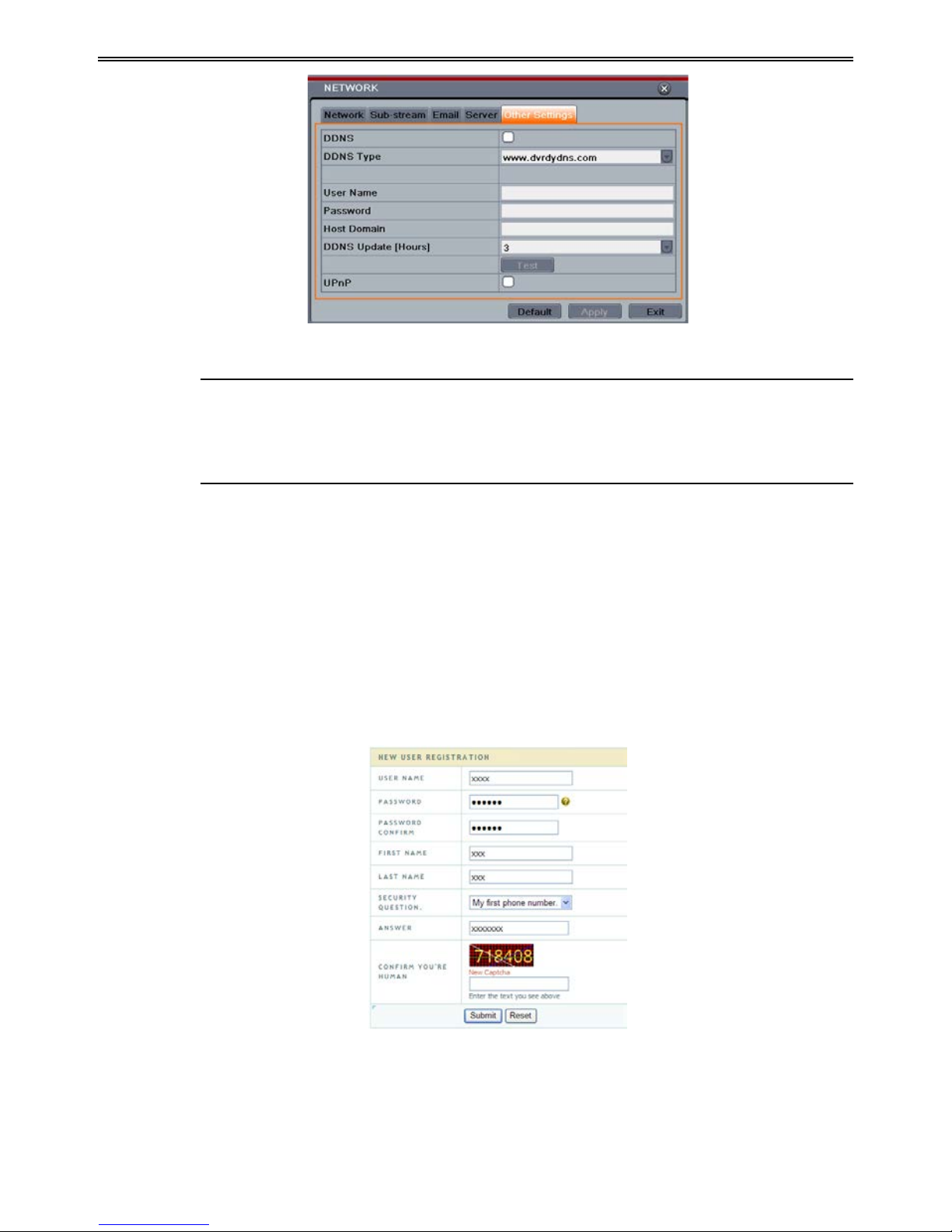
4.6.5 Other Settings
If you r DV R i s se t to u se PPPoE as i ts de fau lt ne tw ork conne cti on, you ma y se tu p DDN S to
be used in connection. The setting steps are as follows:
St ep 1: Enable DDNS server.
St ep 2: Sele ct DDNS server.
St ep 3: E nter user name, password and host domain name of the registe r ed webs i te.
St ep 4: C lick “Test” but ton to test the effectiveness of the relevant information.
Step 5: Click “ Apply” button to save the setting .
29
DVR User Manual
Fig 4-28 Network Configuration-Other Settings
Note: The domain name selected by user is a banding domain name of DVR. User
should logon the website provided by the server supplier to register a user name and
password and then apply for a domain name online. After t he successful application,
user can acc ess the device from the IE client by inpu tting tha t domain name.
Enable UPnP: Select UPnP here and then enable UPnP function in your router. Therefore,
there is no need for you to forward LAN IP address and port in the router in connection of
internet. After that, you can check the WAN IP address in the rout er.
Domain name Registr ation (Take www.dvrdydns.com for example)
Step 1: Input www.dvrdydns.com in the IE address bar to visit its website. Then click
“Registration” butt on to regist er as shown below.
Step 2: Create domain name.
30

DVR User Manual
Ste p 3: After you successfully request your domain na me , you will see your domain in th e l i st.
DVR Setting
Connect DVR to t he Netw ork Cli e nt.
St ep 1: Enter into Main menuNetworkOth er S ettings, checkmark DDNS, select
“dvrdydns” at the DDNS Sever pull down list box and input user name and password.
St ep 2: Enter i nto configurati on interface of the rou ter to m ap the s e rver port an d IP a ddress (if
th e user en ables UPnP func tion , he can skip this step). Click Save button to save the setting
St ep 3: Logi n IE br ow ser and input registered dom ain nam e “http://w w w.xxx.dvrdydns.com:
port”, connect t o D V R client.
You can al so qui ckly re gister the d om ain na m e in this interface .
St ep 1: Set the IP address manually in the network tab a nd then click “Other Se ttings” tab.
St ep 2: Check “DDNS”.
St ep 3: Select “www.autoddns.com” in DDNS Type col umn as shown above.
St ep 4: Enter the host name at random, like 123.
St ep 5: Click “Register” to register the domain name. When the succes sful prompt pops up, it
means you are successfully register your domain name .
If your IP address is not WAN IP address, you should forward your IP address and por t in your
router or enable UPNP function both in r outer and DVR. Then you can use the domain name
31

DVR User Manual
plus HTTP por t to acce ss your D VR.
DDNS server
DDNS ser ver
Website provided by dynamic domain name supplier. The optiona l: www.meibu.com ,
www.dyndns.com, www. no-ip.com, www.dvrdydns.com
, www.autoddns.com and
mint dns type.
User name
User name fo r log in t he website of d omain name supplier
Password
Password for log in the website of d o main name sup pli e r
Host domain
The domain name user registered at the supplier’s website.
Update interval
The interval t i me of upgrading DVR IP address
4.7 User Management Configuration
This tab allows you to add norm al or advanced user s. To add user and setup u ser authori ty:
St ep 1: Enter into MenuSetupUsers. Refer to Fig 4-29:
Fig 4-29 User Management Configuration
St ep 2: Cl ick Add butt on to display a dialog b ox as Fi g 4 -30:
Fig 4-30 Add-General
32

DVR User Manual
St ep 3: In General tab, input us ername, password and select user type. You can also check
“Binding PC MAC Address” and input this addre ss.
St ep 4: Clic k “ O K” to save th e se tting.
Note: When the default value of binding PC MAC Address i s 0, the u ser i s not bou nd
with the specified computer. If the bind option is used, the user would be able to log
into the DVR only th rough the specific computer (carryin g the MAC addr e ss).
St ep 5: Select Authority tab and then as sign the oper at io n rig ht s fo r particul ar user. Refer to
Fi g 4-31.
St ep 6: Clic k OK to save the setting.
Fig 4-31 Add User-Authority
To delete user:
St ep 1: Enter into MenuSetupUsers interfa ce.
St ep 2: Select the added user you want to dele te and th en clic k “D el ete” but ton.
To modify user:
St ep 1: Enter into MenuSetupUsers interfa ce.
St ep 2: Select the added user you w ant t o m odif y and the n click “ Modif y” butt on to d o t he
relevant operation.
To ch ange us er pass w ord
St ep 1: E nter i nto Men uSetupUsers interfa ce.
St ep 2: Se lect the added user you w ant t o change its password and then click “Change
Password” button.
4.8 P.T.Z Configuration
P.T.Z configuration includes two submenus: serial port and advanced.
Serial port settin gs are as follows:
St ep 1: Enter into MenuSetup P.T.Z Serial Port interface. Refer to Fig 4-32:
33

DVR User Manual
Fig 4-32 P.T.Z Configuration-Serial Port
St ep 2: Select “Enable” and setup the value of address, baud rate and protocol accordi ng to th e
se t t ings of the sp eed dome .
St ep 3: Select “All” to set the same settings for all channels.
Advanced settings include preset se tting, cruise setting and track setting.
Enter into MenuSetup P.T.Z Advanced. Refer to Fi g 4-33:
Fig 4-33 P.T.Z configuration-advanced
Parameter
Meaning
Address
The address of the PTZ device
Baud rate
Baud rate of the PTZ device. Range form: 110, 300, 600, 1200, 2400,
4800, 9600, 19200, 34800, 57600, 115200, 230400, 460800, 921600.
Protocol
Communication protocol of the PTZ device. Range from: NULL,
PELCOP, PELCOD, LILIN, MINKING, NEON, STAR, VIDO,
DSCP, VISCA, SAMSUNG, RM110, HY, N-control.
Simulative
Cruise
If enabl ed, no mat ter whether the PTZ device supports cruise or not,
the presets will cruise.
34

DVR User Manual
To set up p reset:
Step 1: In the Advanc ed interface, click pr eset “Setti ng” button to see a dialog box as Fig
4-34:
Fig 4-34 Advanced-Preset Setting
Step 2: In the preset setting tab, enable preset, set the pr eset name and then click preset
“Setti ng” button.
Fig 4-35 Preset Setting
St e p 3 : C ont r ol th e dom e by rotating up, up left, down, right down, left, l eft down, ri ght and
up r ight an d adju st the rotate speed and the value of zoom, focus and iris of the dome.
Step 4: Select the serial number of the preset point. Click
button to enable the PTZ wiper
and click
button to enable the PTZ light.
Note: PTZ must support wiper and light button and these two buttons are just available
when selecting PELCOP or PELCOD.
St e p 5 : Click Save button to save the setting. Click
icon to hide the tool bar. Right click
to view this bar again. Click
icon to ex i t the curr ent interface.
St ep 6: Return to the
Advanced-Preset Setting interface and click OK button to save the setting.
To set up cruis e :
Step 1: In the Advanced interface, click cruise “Setting” button to see a window as shown in
Fig 4-36:
35

DVR User Manual
Fig 4-36 Cruise Setting
St ep 2: Click Add button to add cruise line in t he list box (8 cruise lines ca n b e added at most).
St ep 3: S elect a cruise l i n e and cli ck Setup bu t ton to see a dialog box as Fig 4-37:
Fig 4-37 Modifying Cruise Line
St ep 4 : Click Add icon
to set the speed and time of preset point. Select a preset point
and then cli ck Del ete i con
to delete that preset point. Click Modify icon to mod i f y
th e sett ing of a pr eset p oin t. Use r can cli ck
t hos e i cons t o adj ust th e pos iti on
of pr eset p oint. C lick Pr evie w butt on to previ ew the cr uis e li ne. Cli ck OK butt on to sa ve the
setting.
To set up track:
Step1: In the Advanc ed interface, click track “Setting” button to see a dialog box as Fi g 4-38:
St e p 2 : Control the dome by rotating up, up left, down, right down, left, left down, right and
up r ight an d adju st the rotate speed and the value of zoom, focus and iris of the dome.
St e p 3 : Cli ck Sta rt Re cord but ton t o recor d th e move t ra ck of PT Z. Cli ck th is butt on a ga i n t o
stop record.
St ep 4: Click Start track button to play recorded track. Click this button again to stop playing.
St ep 5: Click
icon to exit the current interface.
After the completion of settings, please remember to click “Apply” to save the setting.
36

DVR User Manual
Fig 4-38 Track Setting
4.9 Advanced
Advanced configur at i on includes t hree submenus: reset, import/export and Block/Allow list.
4.9.1 Reset
Reset all settin gs the device will r eboot.
4.9.2 Import/Export
User can export the data files into mobile storage de vi ces as b a ckup fu n ct i on, and t he n i mp ort
specified data files from mobile storage device to DVR.
4.9.3 Block/Allow List
Fig 4-39 Block/ Allow List
Here aut horized user can pr ohibi t com put er use rs with i n a certain IP ad dress range from
acce ssi ng to DVR or allow computer u s ers wit hin a ce r tain IP addres s range to access DVR.
E.g. if an admin user doesn’t want computer us ers within IP address range from
192.168.000.002 to 192.168.000.004 to access the DVR, he can check Block list option, and
then input such IP address range. If it is required that computer users wi t hin a certain IP
address range access DVR, they can check Allow List option and then do th e required setting.
37

DVR User Manual
5 Search, Playback & Backup
Search configuration includes four submenus: ti me search, event search, file management and
image.
5.1 Time Search
St ep 1: Enter into MenuSearch Time Search. Refer to Fig 5-1:
Fig 5-1 Search Configuration-Time Search
St ep 2: Select date and cha nnels on the right hand side and press the ‘Search’ button. A date
with highlighted borderline indicates presence of data.
St e p 3 : Set the start time by clicking a particular grid or by entering the specific value in the
start time field.
Step 4: Select the channel display mode and click
button to play record. Use the
playback toolbar to control the playback.
To set backup during a certain period in the playback interface:
Select the start time by dragging the slider and click
icon . The n sele ct the end t ime and
click this icon again to confirm the record period. Next, click
icon to bac kup the record
during this period.
5.2 Event Search
St ep 1: Enter into MenuSearchEvent Search button. Refer t o Fig 5-2:
38

DVR User Manual
Fig 5-2 Search Configuration-Event Search
Step 2: Select date and channels on the right hand side. A data with highlighted borderline
in dicates presence of da t a.
St ep 3: C heckmark Motion, S ensor or All accordi ngly.
St ep 4: Click Search button to display the searched event information i n the event list box.
Step 5: Double che ck a certain recor d file to playba ck .
5.3 File Management
St ep 1: Enter into MenuSearchFile Management interface. Refer to Fig 5-3:
Fig 5-3 Search Configuration-File Management
St ep 2: Select date and channels. The date with highlighted borderline i ndicates presence of
data.
St ep 3: Click Search button to display the searched files in the file list box.
St ep 4: Use “All ” button to lock /unlock or delete all files in the fi le man a ge me nt column.
39

DVR User Manual
St ep 5: Double click an unl ocked item to play.
Lock: Select a file and click Lock button to lock this file, after that, that file will not be
deleted or covered.
Unlock: Select a locked file and click “Lock” button to unlock this file
Delete: Select an unlocked file and click “Delete” button to delete this file.
5.4 Search by Image
St ep 1: Enter i nto Men u Search Image tab.
St ep 2: Select data and channels on t he right hand side.
St ep 3: Press “Search” button to sear ch for a recorded image.
St e p 4 : Once an al arm i mage has b een i dent ifi ed, the us er ca n doub le cl ick t he i mage to pla y
recording.
Fig 5-4 Search Configuration-Image
Lock: Select the image and click “Lock” butto n to loc k this imag e.
Save: Click “S ave” but ton t o c opy the image on the HD D .
Save All: Click “Save All” button to copy all images on the HDD.
5.5 Backup
This unit support s backup by built-in SATA DVD Writer with USB Flash. You can also make
backup by IE browser via internet (see section 7.3.2 R emote b ackup).
St ep 1: Enter into b ackup configu ration. Refer t o Fig 5-5:
St ep 2: Set the sta rt & end time, select chann els and click Search but ton to di splay the
searched data in the dat a bac kup l is t bo x.
40

DVR User Manual
Fig 5-5 Backup Configuration
St e p 3 : Select a required fil e or checkmark “All” to select all data files. Click Backup button
to display Backup information window.
St e p 4 : In the backup information interface, you can check the relevant information of backup
files, storage type, save file type, etc. Then click Start button to start backup.
Note: If the backup files are saved in DVR format, please check backup player. Only
this player can play these files in DVR format. If the backup files are saved in AVI
format, you c an play these files wit h common media player.
41

DVR User Manual
6 Manage DVR
6.1 Check System Information
Check system informat ion includes six submenus: system, event, log, network, online user and
record.
6.1.1 System Information
In this interface, you can check the hardware version, MCU version, kernel version, device ID,
etc.
6.1.2 Event Information
In this interface, you can search for events like motion, sensor and video loss. The utility
pr ovid es an i nter face to ha ve a date b ase d and a cha nnel base d sear ch. T his re port can fu rth er
be saved on a USB flash dri ve as an html file using the export button.
6.1.3 Log Information
In this interface, you can search for rel evant l ogs as per set date and event which includes
Operation, Setup, Playback, Backup, Search, Check Information and Error. This report can
further be saved on a USB flash dri ve as an html file using the export button.
6.1.4 Network Information
In this interface, you can check relevant parameters of net w ork.
6.1.5 Online Information
In this interface, you can check th e details of the connected onl i ne use rs.
Refresh: Refresh the current interface.
Disconnect: Disconnect the onli ne us er s t o acces s DVR. If this function is used by t he a dmin,
th e p ar ticul ar PC wil l not be able to access the device for five minutes.
6.1.6 Record Information
In this interface, a user can check resolution, ftp and record status including sensor alarm
re cordi ng, mot ion re cordi ng, manual re cordi ng or sch edul e r ecording.
6.2 Manual Alarm
In this interface, you can t rigger a manual alarm.
6.3 Disk Management
To format the disk
42

DVR User Manual
St ep 1: Enter into disk ma nageme nt interfa ce
Note: please format th e hard disk b efore record.
St ep 2: Click Refresh button to refres h the dis k informat io n in the list box.
St ep 3: Se lect a hard di s k and click For m at button t o start format.
Note: All recorded files in the ha rd disk will be lost after formatting.
To ch eck other inf ormation of disk
After you enter into Disk ManagementAdvan ced tab, you can che ck mode l, S/ N, fir mware,
health status of the disk in this interface. You also can monitor the temperature, internal circuit,
di electr ic materi al of the disk, analysis the pot entia l probl ems of the d isk and w arn so as t o
pr otect it s data.
6.4 Upgrade
At pr ese nt, it on ly sup ports USB upd ate. Get the soft war e from you r ven dor whe n there is a
new software version.
The upgrade steps are as follows:
St ep 1: Copy the upgrade softw are which gets fr om vendor into the USB stora ge devi ce.
St ep 2: Connect t he USB fl ash dr ive to the USB port.
St ep 3: Enter MenuUpgra de tab. You will see the upgra de softw are name displa yi ng in th e
upgrade list box.
St ep 4: Select that software and then click Upgrade button. The system will be upgra ded
automatically.
Note: Please wait for a while when t he system reboots. Any power interruption is not
allowed during upgrading.
6.5 Logoff
A l og o ff d i al ogue b ox w ill p op up by clicking Log off icon. Then click OK button to confi r m
to log off. If you want to log in again, click
icon to enter user name and password to
re-login.
43

DVR User Manual
7 Remote Surveillance
7.1 IE Remote Surveillance
In ord e r t o vi e w th e DVR fr om a ne t wor k it mu st be c onn e ct ed t o LAN/ WAN or int e rn et . The
network setup should be done accordingly. Please refer to 4.6 Network Setup. This DVR
supports IE browser, on Windows XP and Vista platform.
7.1.1 On LAN
St ep 1: Enter into the DVR’s Main MenuSetupNetwork interface to inp ut IP addre s s,
Subnet Mask, etc .If using DHCP, pleas e ena ble DHCP in both the DVR and the router.
St ep 2: Enter Record Setup to set network video parameters like resolution, frame rat e etc.
St ep 3: Open IE on a computer on the same network. Input the IP address of the DVR in IE
address bar and press enter.
St ep 4: IE wi ll downloa d Acti veX component automaticall y. Enter the usern ame and p assword
in the subsequent window
Notice: If HTTP port is not 80, other number i nstead, need add the port number after
IP address. For example, set HTTP port as 82, need input IP address like
192.168.0.25:82.
Use r name an d passwor d here are t he same wi th that us ed on the DVR. The defaul t
username and password is admin and 123456.
7.1.2 On WAN
There are two ways for the DVR to connect to internet.
1. Connect the DVR to internet through router or virtual server
Step 1: Enter into the DVR’s Main MenuSetupNetwork interface to input IP address,
Subnet Mask, etc. If u sin g D H C P, pl ease e nable DHCP in bot h the DVR and router.
St ep 2: Forward IP address and port number in Virtual Server setup of the router or virtual
server. Configure the firewall to allow accessing the DVR. (If the user has enabled the UPnP
function i n both t he DVR an d router, he can skip th i s s tep. )
Step 3: If users want to utilize dynamic domain name, please apply for a domain name in a
DNS server supported by t he DVR or router. Then add to the DVR.
Step 4: Op en IE b rows er, in put IP ad dres s, or dyna mic domain name and enter. If HTTP port
is not 80, add the port nu m ber after IP addr e ss or d omain na m e.
Step 5: IE wil l download ActiveX au tomati cally. Then a w indow pop s up and ask s for user
na me and pa ssword. Inpu t name a nd password corre ctly, and enter to vi ew.
Note: If you cannot download and ins ta ll A c ti ve X , please r efer to FAQ Q8 .
44

DVR User Manual
2. Connect the DVR to internet directly
St ep 1: Enter into the DVR’s Main MenuSetupNetw ork interface to en able PPPoE and
then input user name and password received from your ISP. Next, click ‘Apply’. The DVR
wil l conn ect to the ser ver and w ould gi ve a confirma t ion message.
Step 2: When accessing the remote interface of DVR, user can input WAN IP to access
directly (user can enter into Main menuInformationNetwork interface to check IP
address). The browser will download A ctive X control.
St ep 3: The follow ing se t ting steps are as the same as St ep 4 and Step 5 in P oint 1.
7.2 Remote Surveillance through Apple PC
Note: Because the curren t plug-in version of client end just only supports 32-bit mode,
so the safari browser shall start 32-bit mode. If the browser is the earlier MACOS
version, the default setting is 32-bit mode and the se tting c an be skipped.
The setting steps are as follows:
St ep 1: Right click safari icon and select “Show in Finder”.
St ep 2: Select ApplicationsRight click “Safari. App”Select “Get Info”.
St ep 3: Select “Open in 32- bit m ode”.
7.2.1 On LAN
Step 1: After st artin g Apple compu ter, cli ck Apple icon. The fol lowin g wind ow will p op up.
Please select “System Preferences” “Inter n et &Wireless” “Network”.
45

DVR User Manual
Step 2: Go int o Netw ork int erfa ce and the n cli ck “Ethe rnet C onnect ed” t o check th e inte rnet
connect i on of Apple PC.
St ep 3: After acquiring the IP address, Subnet Mask and so on, please enter into the DVR’s
Main MenuSetupNetwork interface to manually input IP address, Subnet Mask and
Gat eway accor ding t o the con figur ation of PC. The n etwork s egment sh ould be t he same as
the PC. If using DHCP, please enable DHCP in the DVR and router.
St ep 4: After the a bove in forma ti on is comp let ed, you can en ter LAN IP and ht tp por t in the
Saf ari b rows er. For e xampl e: in put http://192.168.1.100:81(here 192.168.1.100 is LAN IP of
DVR, 81 is the http port of DVR), and click “
”button. Then the brows er will download
Act ive X con trol as shown below:
Step 5: Click icon and then select the Active X control, the welcome interface will be
shown. Cli ck “Continue” “Install” button,the following window wi ll pop up:
Input the na me and password of Apple PC and then click “OK” to install this Active X cont r ol.
Step 6: After finishing installing the Active X control, please quit from the Safari browser.
Right click Safari icon on the de skt op an d then se lec t “Qui t” b utt on to quit the br owser. Th en
restart Safari browser. Input the IP address and http port to enter into the login interface of
DVR.
46
DVR User Manual
7.2.2 On WAN
There ar e also tw o w ays for DV R to connect t o In ter net.
1. Connect the DVR to internet through router or virtual server
St ep 1 : The network setups are the same as step one to step four of point 1 on WAN of IE
re m ote surveil lance .
St ep 2 : Enter WAN IP and http port in the Safari browser to install the Active control. The
concret e steps ar e the sam e as step 5 an d 6 of Chapt er 7.2. 1 .
2. Connect the DVR to internet directly.
Step 1: The network setups are the same as step one of point 2 on WAN of IE remote
surveillance.
St ep 2 : Enter WAN IP and htt p port in the Sa fari br owser to install the Active control. The
concrete s teps are the sam e as step 5 and 6 of Chap t er 7.2. 1.
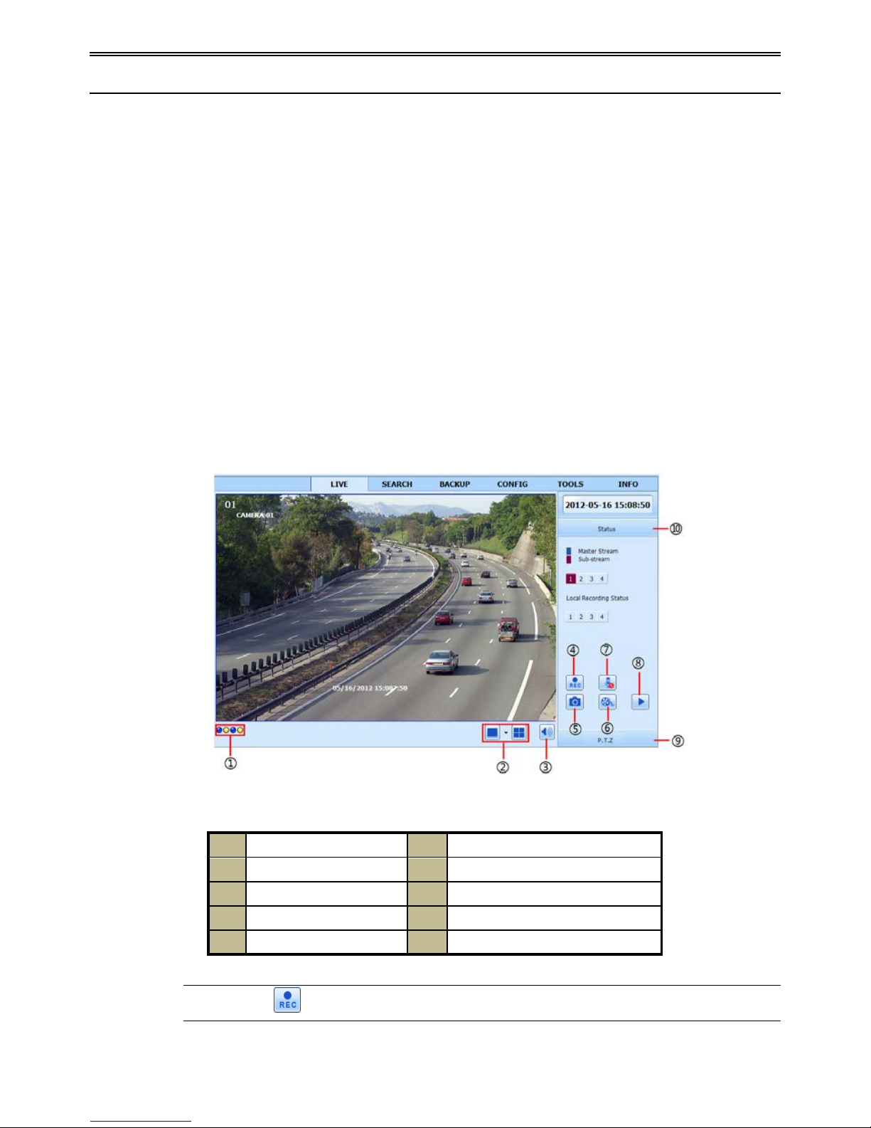
7.3 The Remote Live Preview
Fig 7-1 Remote Live Preview Interface
1
Channel indicator
2
Screen display mode
3
Volume
4
Start rec ording
5
Snapping pic ture
6
Start IE record
7
Bidirectional talk
8
Playback
9
PTZ control
10
Master/sub stream status
Note: Click
button to start recording. The record fil e wi l l b e saved in user ’s PC.
47

DVR User Manual
Screen display mode:
Clic k the
icon beside the screen display mode to sel ect channels.
Snap pictures
Click “Snap”
icon to automatically capture pictures and save those pictures in the
computer. You can set up the save path for those picture in the Remote Preview interface
Configuration Local configuration.
PT Z control
Please connect speed dome to the device via RS485 firstly, make sure the protocol of the
speed dome is supported by the device and set the relative parameters manually. User can
contro l the dome up, down, right, left or stop rota t ing on Control Center, adjust r otation speed,
Iris and zoom, focus on the dome, and set the presets, etc.
Buttons definition:
Buttons
Description
to rotate the dome upwards. t o rota te t he dome d ia gonall y
up-left.
to rotate the dome diagonally up-right to rotate
the dome downwards.
to rotate the dome diagonally
down-right
to rotate the dome diagonally down-left to
rotate the dome towards left.
to rotate the dome towards right
to stop rotating the dome.
Drag the scroll bar to adjust rota ting speed of t he dome.
'Iris' button. Click
butt on near 'I ris' button to inc rease li ght
of the dome. Cli ck
butto n near 'Iri s' butt on t o dec rease light
of the dome.
'Zoom' button. Click
butt on near 'Z oom' butt on to zoo m i n
the locale picture of this camera. Click
butt on near 'Z oom'
button to zo om out the locale picture of t his camera.
'Focu s ' but t on. C li c k
butto n near 'Focu s' butt on to have lon g
focus. Click button near 'Focus' button to have short focus.
Go to the Preset
Select and do auto cruise
Track
Auto sca n
Wiper button
Light button
Click the right mouse on the live interface. This will take you to a pul l-down menu.
48

DVR User Manual
Fig 7-2 Right Key Sub Menu
Stream: This DVR supports master stream and sub stream. Master stream has higher frame
rate, max 25FPS
(PAL)/30 FPS(NTSC)for every channel, but it needs higher network
bandwidth simu l tan eously. Sub stream has low frame rate, max 6FPS (PAL)/7FPS(NTSC)
for every channel, it requires low network bandwidth. Therefore, you can select the stream
acc ordi ng to your bandwidth.
All to master/sub stream: Set all channel to master stream or sub stream.
Enable audio: Enab l e or dis enabl e audi o.
Full screen: The l ive preview picture will display with full screen and the tool bar will be hid.
Double click left mouse or click right mouse to return.
Zoom i n : Singl e chan nel la rge s cr een ele ct ron i c amp li fi cati on . Click the channel which needs
to be zoo me d . Ri gh t cli ck t o se le ct zoom i n but t on t o zoom i n the im age . Dou bl e cl ic k or ri gh t
click to ex it.
7.4 Remote Playback & Backup
7.4.1 Remote Playback
Click button to go into record playback interface. Refe r to Fig 7 -3:
Select the record date a nd channels and double-click the f ile name in th e record file list b ox.
Then you can play t hat file and preview the picture.
Fig 7-3 Play Record File Interface
49

DVR User Manual
This DVR supports remote time search, event search and file management.
By Time Search:
St ep 1: Enter into SearchTime Search. Re f er to Fig 7-4:
St ep 2: T he highl ight date in t he are a② indicates recorded dat a. S el ect the date in area ② and
record channels in area③.
St ep 3: Click “Search” button. The record data will be displayed in the data information list
box.
St ep 4: Set the data playing time and display mode in the area① as required.
St ep 5: Click “Play” button to playback. 8 CH DVR only supports single channel di splay.
Fig 7-4 Time Search Interface
Step 6: Click the relevant buttons in the interface for operation, like FF, pause, change channel
mode , etc. Refer to Fig 7-5:
Fig 7-5 Time Search Playback
By E vent Search:
50

DVR User Manual
Step 1: Enter into SearchEvent Search interface. Re fer to Fig 7-6:
St ep 2: Click the highlight date and select record channels.
St ep 3: Checkm ark th e event t ype: mot ion and sensor.
St ep 4: Click “Search” button.
St ep 5: Double-click certain item to play.
Fig 7-6 Event Search Interface
File Man ag em ent
St ep 1: Enter into SearchFile Management interface. Refer to Fi g 7-7:
Fig 7-7 File M anagement Interface
St ep 2: Se lect highlighted dat e and channel s.
St ep 3: Click “Search” b utton t o search the recorded files.
Lock: Se le ct ce rta in fi le it em in the f ile l ist b ox and t hen cl ick “ Lock” butt on to l ock t his fi le
th at ca not be d elete d or overlaid.
Unlock: Select a locked f ile and t he n click “Unlock” button to unlock this fi le.
Delete: Select an unlock file and then click “Delete” button to delete this file from file list.
51

DVR User Manual
7.4.2 Remote Backup
Clic k B a ckup button to enter into bac ku p interfa ce. Please re fer to Fig 7-8:
Fig 7-8 Remote Backup Interface
St ep 1: Se lect channels, set the start and end time and then click “search’ b utton to d isplay the
file information in the file list box.
St ep 2: Se lect backup files and cl ick “Brow se” button t o s et the save path. The n click
“Backup” but t on to start backup. The backup files will be saved on user’s PC.
7.5 Remote Syst em Configuration
You can do r emot e set up of t he devi ce whi ch i ncl udes f unct ion s like b asi c confi gur at ion , li ve
configuration, record configuration, schedule configuration, alarm configuration, network
configuration, PTZ configuration and user configuration. You should select an option from the
menu list on the left and then setup the relative parameters. Only one user can do
con figur ation set up at a given point of time. Click Config tab to e nt er into the be low interface
The sub menu list and the opti ons in every menu are similar to that of the DVR. Please refer to
Chapter 4 Main Menu Setup Guide for mor e details.
Fig 7-9 Remote Menu Setup
52

DVR User Manual
7.6 Tools
Click on the tool’s tab to access the Disk Management tool. The user can view the s tatus of
the hard drive(s), can view/change the read write properties and can also format the hard
drive(s).
7.7 Remote M a na gement
The Info inter face provides a web based interface to access the general infor mation pertaining
to the DVR’s settings. The interface includes five submenus: System, Event, Log, Network
and Online users.
Note: There may be subtle differences with respect to functions of remote surveillance
between through IE and through Apple PC. Here we only take IE remote access for
example.
53

DVR User Manual
Appendix A FAQ
Q1. Why the DV R d oesn’t turn on after connecting to the p ower?
a. The power adapter could have gone bad. Please change a new power adapter.
b. The power from t he adapter m ay be not e nough for operating the DVR . Please use the
power adaptor s uppli ed alon g w ith the DVR.
c. It could be a ha r dware problem.
Q2. There i s not menu displayed and only has live image di splay.
a. Check whether the monit or is conn ect ed to the main vi deo ou t a nd not the s pot out. The
monitor m ight be c onnected to VG A port whereas the DVR may be set for output through
BNC or vice versa. Long press ES C key to toggle t he out put mode s.
Q3. The DVR LED turns on, however there is no output.
a. The power from the adapter may be not enough for operati ng the DV R. Please us e the
power adaptor s uppli ed alon g w ith the DVR.
b. It could be a wiring issue. Please check t he connection for the sa me.
c. Check the moni tor settings.
Q4. Why are no imag es dis played on few or all channels of the DVR ?
a. It could be a wiring issue. Pl ease check the cable and the ports of the cameras and DVR.
b. The problem can al so be related to camer as. Please check the same.
c. Pleas e mak e sure t hat t he ch ann el s ar e not pr ogr amm ed as hi d den ch an n els an d check the
status from admin login.
Q5. The HDD cannot be found.
a. The powe r from t he adapte r may be not e nough for operat ing the DVR . Pleas e use the
power adaptor s uppli ed alon g w ith the DVR.
b. It could be wiring issue. Please check the power and data cables of the HDD.
c. The HDD could have gone bad. Change a new one.
Q6. The DVR cannot rec ord.
a. Make s ure the H DD was for m atted pri or to use.
b. Maybe the user hasn’t enabled the record function or has done incorrect setup. Please
refer to Chapt er 5.
c. Maybe HDD is full and thus the DVR is not able to record. Check HDD information
from D isk Ma nagem ent an d i f r equired, pleas e e nable t he re cycle functi on.
d. The HDD could have gone bad. Please change another one.
Q7. Mous e doesn’t work.
a. The mou se should be connected t o t he USB port at t he rear si de.
54

DVR User Manual
b. After connect i ng the mouse, allow the DVR to detect the mouse for seconds . If not detected,
try restarting the DVR.
c. The mouse may be incompatible. Please change a mouse.
Q8. ActiveX control cannot be downloaded.
a. IE browser blocks ActiveX. Please do setup as per the st e ps mentioned below.
Step1: Op en IE brow ser. Click ToolsInternet Options.
Step 2: Select SecurityCust om Level. Refer to Fig 8-1
St ep 3: Enable all the sub options under “ActiveX controls and plug-ins”. Refer to Fig 8-2
Th en cli c k Ok t o finish setu p.
b. Other plug-ins or anti-virus blocks ActiveX. Please uninstall or do the required settings.
Fig 8-1 Fig 8-2
Q9: DVR displays “please wait…”all the time.
a. HDD power cable and data cable may not be well connected. Please check the
conn ecti ons for HDD.
b. It i s also p ossib l e that t he DVR was forced to stop be cause HD D has a bad s ector and it
may have caused the system to halt. Check with a good known HDD or t r y formatting the
existi n g HDD.
55

DVR User Manual
Q10: How t o input password and di gital numbers?
Cl ick the pass w ord or th e input box a small keyboard will pop up. Ple ase select ch aracters to
be input (t he initial password is 123456), or you can use the digital keys on the front pane l, or
the digital keys on the remote controller.
Q11: A hard disk is bein g identified as a new device however it was be ing used with
another DVR of same model. Should it be formatted prior use?
It i s possi ble to m igrate an HDD f rom one DV R t o anot her pr ovided t hat the DVRs are of the
same mode l and that the HDD being migrated would be used as the sole disk in the new DVR.
Howe ver i n cases w here the new DV R alrea dy conta ins a HD D , the migrated dis k being
in s talled would have t o be formatted. In gen eral migratin g disks from one D V R to another is
not recommended.
Q12: What is the minimum configuration required for remote monitoring?
PC M o dule
Parameters
CPU
Intel Celeron 2.4G
Motherboard
Intel 845
HDD
80G
RAM
512M
VGA
NVIDIA GeForce MX440/FX5200 ATIRADEON 7500/X300
OS
Windows 2000(SP4 above) /Windo ws XP(SP 2 above ) /VISTA
DirectX
9.0
Q13: How to handle the situation t hat the codec Control is blocked when downloading in
the VISTA or Win7 system?
This prob lem can be fix ed in tw o w ays:
a. Enter Control PanelUser Account and Family Safety User Acco u n t Control (refer to
the following figure) and click Turn User Account on or off. Cancel Use User Account
Control ( U AC ) to he lp protect you r compu ter.
b. Right click IE browser (refer to the following figure) and select Run as administrator to
ru n browser.
56

DVR User Manual
Q14. How to play the backup f ile ?
Insert your USB de vice where the backup files are saved i n the USB port of PC. If your files
ar e saved in DVR format, you must have already downloaded the backu p player box be fore
doing backup. Then double click to open your USB disk to find your backup files and backup
player. Double click
icon to install backup player. After you install it, open this
pl ayer an d click “ Open Pat h” butt on to ope n your ba ckup fil e. Next, cl ick
pl ay b utt on to
play the backup file. Double click the image and then right click to enable audio. If you save
your backup files in AVI format, you can directly open your file by using the media player
which supports this format.
57

DVR User Manual
Appendix B Calculate Recordin g Capacit y
Users can calculate the size of hard disk according to the saving time and DVR recording
settings. The DVR uses fixed video bit rate. The below are the details at different settings.
Resolut
ion
Frame Rate
Totally(FPS)
Video Quality
Bit Rate
(kbps)
Used
Space(MB/h)
1080P
25(PAL)/
30(NTSC)
Highest
12M
5400
Higher
9M
4050
Medium
7M
3150
Low
6M
2700
Lower
4M
1800
Lowest
1.5M
675
The calculation format is: Total Recording capacity =Used space per hour (MB/h)
(c overage rat e of hard disk) × record i n g time (hour) × channel numbers
For instance, one customer uses NTSC cameras, set resolution to 1080P, video quality to
Lowest, frame rate to 30 fps for enabling total 4 channels. He wants the unit to record
continuously in a month. Bel ow is the calculation:
Total Recoding capacity =675 (mb/h) X 24(hours/day) X30(days) X4(channels)= 1944000
(MB)≈1898(GB)
Therefore, customers just install two SATA HDDs with 1TB, it can almost record for one
month.
58

DVR User Manual
Appendix C Compatible Devices
1. Compatible USB dri ve after test.
Brand
Capacity
SSK
512MB, 1G, 2GB
Netac
4GB
Kingston
2GB
Aigo
2GB
Smatter vider
1GB
SanDisk
4GB
2. Compat ible SATA CD/DVD writers after test
Brand
Model
TECLAST
GH22NP20/TL-22XD
BENQ
DW220S-0K4
LITEON
DH—20A6S01C
LITEON
DH-20A4P02C
SAMSUNG
TS-H653B
3. Compatible HDD list
Brand
Capacity
Seagate Barracuda
80G/160G/250G/320G /1.5T/2TB/3TB
Seagate SV35.3
1T
Seagate Pipeline HD.2
500G
Maxtor Dia m ondmax
160G
HITACHI Desk star
80G/160G
WD WD1600JS
160G
Samsung HD161HJ
160G
59

DVR User Manual
Appendix D 4 CH Specifications
Compression format
H.264 Main Profile
Video output
CVBS×1, VGA×1 , HDMI×1
Vide o Input
SDI×4
HDMI/VGA Resolution
1080P/1280*1024/ 800*600
Rec or d Resolution 1080P (1920*1080)
Display Frame Rate
100 FPS (PAL), 120FPS (NTSC)
Record Frame Rate
100FPS (PAL), 120FPS (NTSC)
Audio I nput
RCA X4
Audio out p ut
RCA X1
Alar m Inp ut
NO or NC 4CH
Alarm output:
4CH
Rec or d Mode
Manual / Sensor /Timer / Motion detection
Simplex/Duplex/Triplex
Pentaplex
Network Interface
RJ45 (LAN, INTERNET)
PTZ control
YES
Com m unication inte rface
RS485, USB2.0 x 2 ( one for bac kup, a nother for
USB m ouse )
Disk info
SATA x 1 +DVD-R W x 1 or SATA x 2
Remote controlle r
YES
Po wer Supply
DC12V
Temperature
0℃-50℃
Humidity
10%-90%
60

DVR User Manual
Appendix E 8 CH Specifications
Compression format
H.264 Main Profile
Video output
CVBS×1, VGA×1 , HDMI×1
Vide o Input
SDI×4
HDMI/VGA Resolution
1080P/1280*1024/1280*768/ 800*600
Record Resolution 1080P (1920*1080)
Display Frame Rate
200 FPS (PAL), 240FPS (NTSC)
Record Frame Rate
200 FPS (PAL), 240FPS (NTSC)
Audio I nput
RCA X4
Audio out p ut
RCA X1
Alar m Inp ut
NO or NC 8CH
Alarm output:
1CH
Rec or d Mode
Manu al / Sensor /T ime r / Motion detection
Simplex/Duplex/Triplex
Pentaplex
Network Interface
RJ45 (LAN, INTERNET)
PTZ control
YES
Com m unication inte rface
RS485, USB2.0 x 2 ( one for bac kup, a nother for
USB m ouse )
Disk info
SATA x 1 +DVD-R W x 1 or SATA x 2
Remote controlle r
YES
Po wer Supply
DC12V
Temperature
0℃-50℃
Humidity
10%-90%
61

450011000460 A1
 Loading...