

hittite HMC494LP3 User Manual

查询HMC494LP3供应商
10
MICROWAVE CORPORATION
v01.0604
Typical Applications
Prescaler for DC to 18 GHz PLL Applications:
• Point-to-Point / Multi-Point Radios
• VSAT Radios
• Fiber Optic
• Test Equipment
• Military
Functional Diagram
HMC494LP3
SMT GaAs HBT MMIC
DIVIDE-BY-8, DC - 18 GHz
Features
Ultra Low SSB Phase Noise: -150 dBc/Hz
Very Wide Bandwidth
Output Power: -4 dBm
Single DC Supply: +5V
3 x 3 x 1 mm QFN Package
General Description
The HMC494LP3 is a low noise Divide-by-8
Static Divider utilizing InGaP GaAs HBT technology packaged in a leadless 3x3 mm QFN surface
mount plastic package. This device operates from
DC (with a square wave input) to 18 GHz input
frequency from a single +5.0V DC supply. The
low additive SSB phase noise of -150 dBc/Hz at
100 kHz offset helps the user maintain excellent
system noise performance.
FREQ. DIVIDER & DETECTORS - SMT
10 - 130
Electrical Specifi cations, T
Parameter Conditions Min. Typ. Max. Units
Maximum Input Frequency 18 19 GHz
Minimum Input Frequency Sine Wave Input. [1] 0.2 0.5 GHz
Input Power Range Fin = 2 to 12 GHz -15 -20 +10 dBm
Output Power Fin = 0.5 to 18 GHz -7 -4 dBm
Reverse Leakage Both RF Outputs Terminated 55 dB
SSB Phase Noise (100 kHz offset) Pin = 0 dBm, Fin = 6 GHz -150 dBc/Hz
Output Transition Time Pin = 0 dBm, Fout = 882 MHz 100 ps
Supply Current (Icc1 + Icc2) 103 mA
1. Divider will operate down to DC for square-wave input signal.
For price, delivery, and to place orders, please contact Hittite Microwave Corporation:
12 Elizabeth Drive, Chelmsford, MA 01824 Phone: 978-250-3343 Fax: 978-250-3373
= +25° C, 50 Ohm System, Vcc= +5V
A
Fin = 12 to 16 GHz -15 -20 +3 dBm
Fin = 16 to 18 GHz -10 -15 0 dBm
Order Online at www.hittite.com
v01.0604
HMC494LP3
MICROWAVE CORPORATION
SMT GaAs HBT MMIC
DIVIDE-BY-8, DC - 18 GHz
GaAs MMIC SUB-HARMONICALLY PUMPED MIXER 17 - 25 GHz
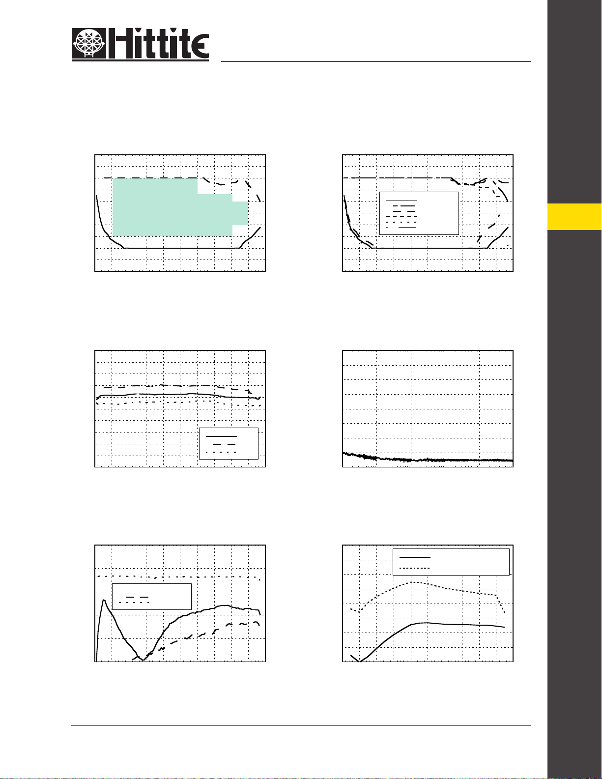
Input Sensitivity Window, T= 25 °C Input Sensitivity Window vs. Temperature
20
20
10
0
Recommended
Operating Window
-10
INPUT POWER (dBm)
-20
-30
0 2 4 6 8 10 12 14 16 18 20
INPUT FREQUENCY (GHz)
Output Power vs. Temperature
0
-1
-2
-3
-4
-5
-6
-7
OUTPUT POWER (dBm)
-8
-9
-10
0 2 4 6 8 10 12 14 16 18 20
INPUT FREQUENCY (GHz)
+25C
+85C
-40C
10
0
-10
INPUT POWER (dBm)
-20
-30
0 2 4 6 8 10 12 14 16 18 20
INPUT FREQUENCY (GHz)
Min Pin +25C
Max Pin +25C
Min Pin +85C
Max Pin +85C
Min Pin -40C
Max Pin -40C
SSB Phase Noise Performance,
Pin= 0 dBm, T= 25 °C
0
-20
-40
-60
-80
-100
-120
SSB PHASE NOISE (dBc/Hz)
-140
-160
2
10
3
10
4
10
OFFSET FREQUENCY (Hz)
5
10
10
6
10
7
10
Output Harmonic Content,
Pin= 0 dBm, T= 25 °C
0
-10
-20
-30
OUTPUT LEVEL (dBm)
-40
-50
0 2 4 6 8 10 12 14 16 18 20
Pfeedthru
2nd Harmonic
3rd Harmonic
INPUT FREQUENCY (GHz)
For price, delivery, and to place orders, please contact Hittite Microwave Corporation:
12 Elizabeth Drive, Chelmsford, MA 01824 Phone: 978-250-3343 Fax: 978-250-3373
Reverse Leakage, Pin= 0 dBm, T= 25 °C
0
-10
-20
-30
-40
-50
-60
OUTPUT LEVEL (dBm)
-70
-80
0 2 4 6 8 10 12 14 16 18 20
Order Online at www.hittite.com
Both Output Ports Terminated
One Output Port Terminated
INPUT FREQUENCY (GHz)
FREQ. DIVIDERS & DETECTORS - SMT
10 - 131
 Loading...