

hittite HMC346LC3B User Manual
查询HMC346LC3B供应商
HMC346LC3B
v00.1204
GaAs MMIC VOLTAGE-VARIABLE
ATTENUATOR, DC - 18 GHz
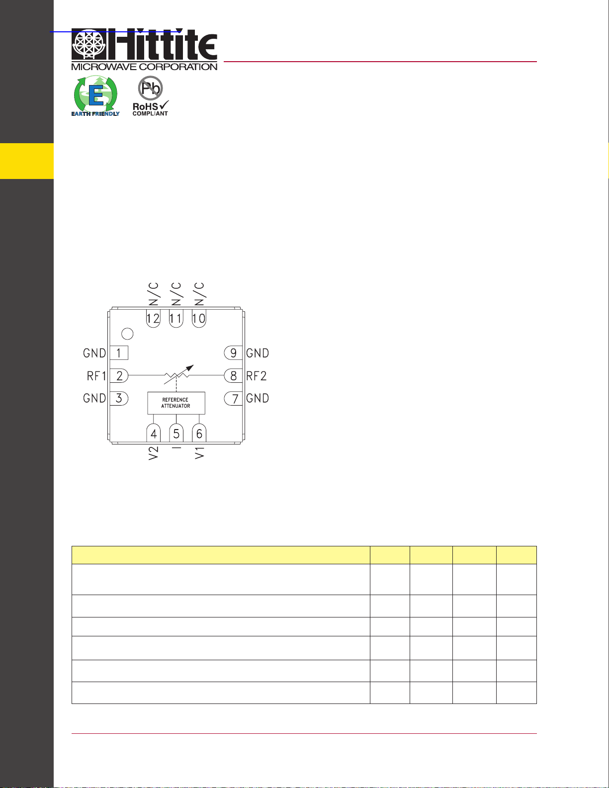
9
ATTENUATORS - SMT
Typical Appli cations
The HMC346LC3B is ideal for:
• Test Instrumentation
• Fiber Optics & Broadband Telecom
• Microwave Radio & VSAT
• Military Radios, Radar, & ECM
Functional Diagram
Features
Wide Bandwidth: DC - 18 GHz
Low Phase Shift vs. Attenuation
30 dB Attenuation Range
Simpli ed Voltage Control
RoHS Compliant 3 x 3 mm SMT Package
General Description
The HMC346LC3B is an absorptive Voltage Variable
Attenuator (VVA) in a leadless “Pb free” RoHS compliant SMT mount plastic package operating from DC 18 GHz. It features an on-chip reference attenuator for
use with an external op-amp to provide simple single
voltage attenuation control, 0 to -3V. The device is
ideal in designs where an analog DC control signal
must control RF signal levels over a 30 dB amplitude
range. The HMC346LC3B allows the use of surface
mount manufacturing techniques.
9 - 90
Electrical Specifications, T
Parameter Min Typical Max Units
Insertion Loss
Attenuation Range
Return Loss
Input Power for 0.25 dB Compression (0.5 - 18 GHz)
Input Third Order Intercept (0.5 - 18 GHz)
(Two-tone Input Power = -8 dBm Each Tone)
Switching Characteristics
For price, delivery, and to place orders, please contact Hittite Microwave Corporation:
20 Alpha Road, Chelmsford, MA 01824 Phone: 978-250-3343 Fax: 978-250 -3373
= +25° C, 50 Ohm system
A
DC - 10 GHz
DC - 14 GHz
DC - 18 GHz
DC - 12 GHz
DC - 18 GHz
DC - 18 GHz 10 dB
Min. Atten:
Atten. >2 dB:
Min. Atten:
Atten. >2 dB:
tON, tOFF (50% CTL to 10/90% RF):
tRISE, tFALL (10/90% RF):
Order On-line at www.hittite.com
26
22
1.5
2.2
2.8
30
26
+8
-4
+25
+10
2.0
2.7
3.5
2
8
dB
dB
dB
dB
dB
dBm
dBm
dBm
dBm
ns
ns
v00.1204
HMC346LC3B
GaAs MMIC VOLTAGE-VARIABLE
ATTENUATOR, DC - 18 GHz
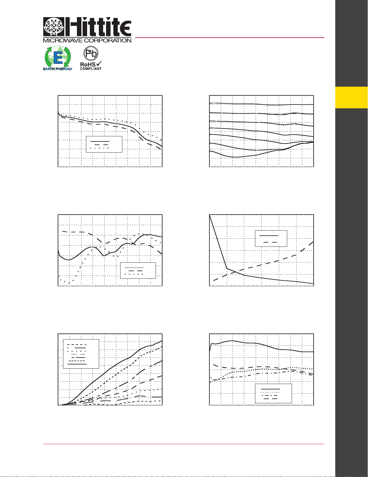
Insertion Loss vs. Temperature
0
-0.5
-1
-1.5
-2
-2.5
-3
INSERTION LOSS (dB)
-3.5
-4
024681012141618
FREQUENCY (GHz)
+25C
+85C
-40C
Return Loss vs. Attenuation
0
-5
-10
-15
-20
-25
RETURN LOSS (dB)
-30
-35
024681012141618
FREQUENCY (GHz)
MIN
5 dB
MAX
Relative Attenuation
0
-5
-10
-15
-20
-25
ATTENUATION (dB)
-30
-35
-40
024681012141618
FREQUENCY (GHz)
Relative Attenuation vs.
Control Voltage @ 10 GHz
0
-0.5
-1
-1.5
-2
CONTROL VOLTAGE (Vdc)
-2.5
-3
0 5 10 15 20 25 30
RELATIVE ATTENUATION (dB)
V1
V2
9
ATTENUATORS - SMT
Relative Phase vs. Attenuation
180
160
140
120
100
80
60
RELATIVE PHASE (deg)
40
20
0
024681012141618
*Two-tone input power = -8 dBm each tone, 1 MHz spacing.
5 dB
10dB
15dB
20dB
25dB
30dB
Max
FREQUENCY (GHz)
For price, delivery, and to place orders, please contact Hittite Microwave Corporation:
20 Alpha Road, Chelmsford, MA 01824 Phone: 978-250-3343 Fax: 978-250 -3373
Order On-line at www.hittite.com
Input IP3 vs. Attenuation*
30
25
20
15
10
INPUT IP3 (dBm)
5
0
024681012141618
FREQUENCY (GHz)
0 dB
3 dB
6 dB
10 dB
9 - 91
 Loading...