

Hittite HMC259 Datasheet
y2k
new!
MICROWAVE CORPORATION
FEBRUARY 2001
HMC259
GaAs MMIC SUB-HARMONICALL Y PUMPED MIXER 28 - 40 GHz
Features
SUB-HARMONICALLY PUMPED (x2) LO
HIGH 2LO/RF ISOLATION: > 35dB
SMALL SIZE: 1.24mm x 1.55mm
IDEAL FOR 38 GHz RADIOS, E1 & T1
4
MIXERS
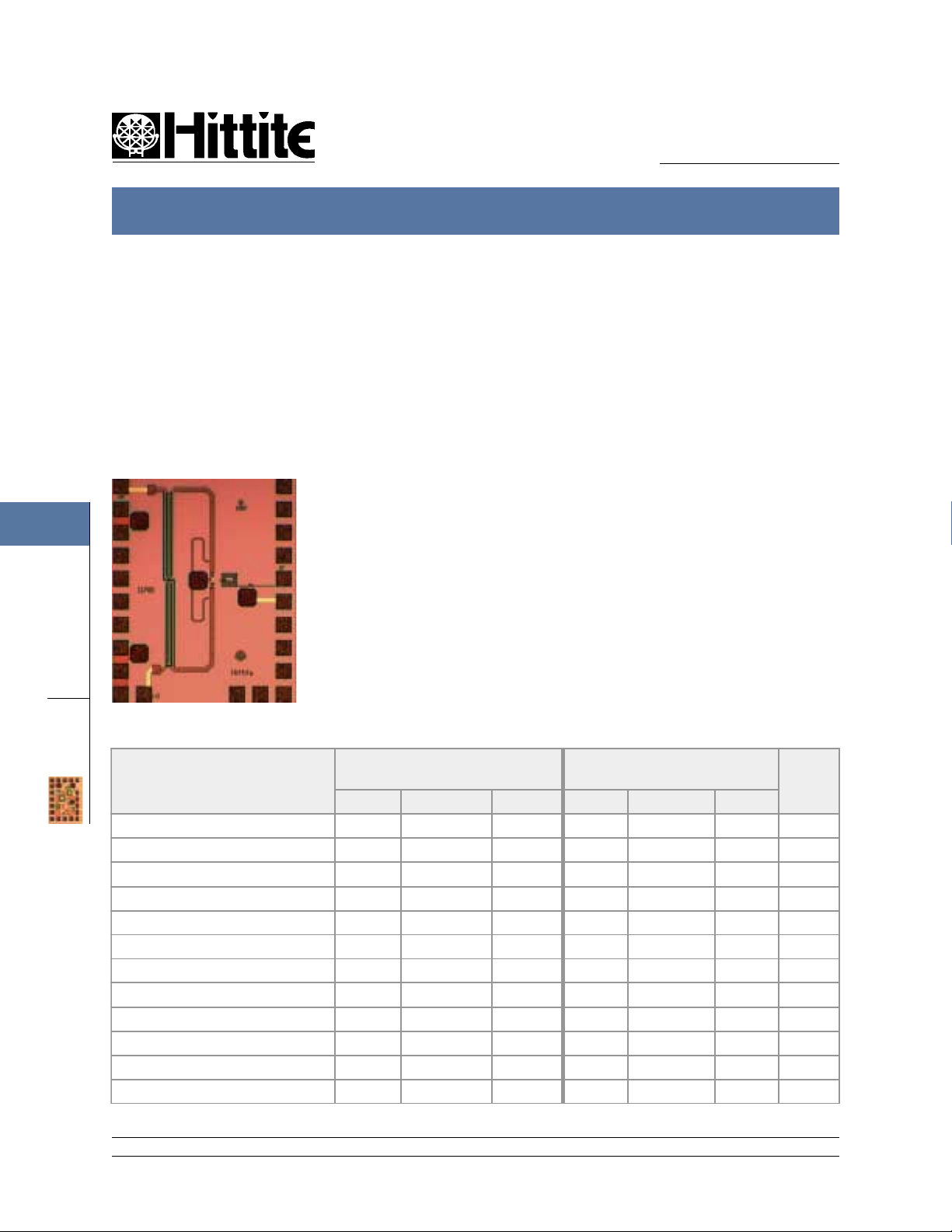
General Description
The HMC259 chip is a broadband sub-harmonically pumped (x2) balanced MMIC passive mixer
which can be used as an upconverter or
downconverter. The chip utilizes a GaAs MESFET
process resulting in a small overall chip area of
1.9mm
of DC-13 GHz. The 2LO to RF isolation is
excellent eliminating the need for additional filtering . This mixer chip is designed to be used in
38GHz point to point radios, Local Multi-Point
Distribution Systems (LMDS), and SATCOM applications. All data is with the chip in a 50 ohm test
fixture connected via 0.025 mm (1 mil) diameter
wire bonds of minimal length <0.31 mm (<12
mils). This device is a much smaller and more
reliable replacement to hybrid diode mixer designs.
2
. This chip has a very wide IF bandwidth
Guaranteed Performance*, LO Drive=+15dBm, - 55 to + 85 deg C
DIE
Parameter
IF = 1 GHz
IF = 1 GHz
Units
Min. Typ. Max. Min. Typ. Max.
Frequency Range, RF 28 - 40 36 - 40 GHz
Frequency Range LO 14 - 20 18 - 20 GHz
Frequency Range, IF DC - 12 DC - 4 GHz
Conversion Loss 14 17 12 15 dB
NoiseFigure(SSB) 14 17 12 15 dB
2 LO to RF Isolation 28 35 40 50 dB
2 LO to IF Isolation 58 65 63 68 dB
RF to IF Isolation 25 30 25 32 dB
LO to IF Isolation 10 15 12 17 dB
IP3 (Input) 2 5 2 6 dBm
1 dB C ompression (Input) -7 -4 -7 -1 dBm
Local Oscillator Drive Level +13 +15 +18 +13 +15 +18 dBm
* Configured as a downconverter
12 Elizabeth Drive, Chelmsford, MA 01824 Phone: 978-250-3343 Fax: 978-250-3373 Web Site: www.hittite.com
4 - 112
MICROWAVE CORPORATION
HMC259 SUB-HARMONICALLY PUMPED MIXER 28 - 40 GHz
new!
HMC259
FEBRUARY 2001
y2k
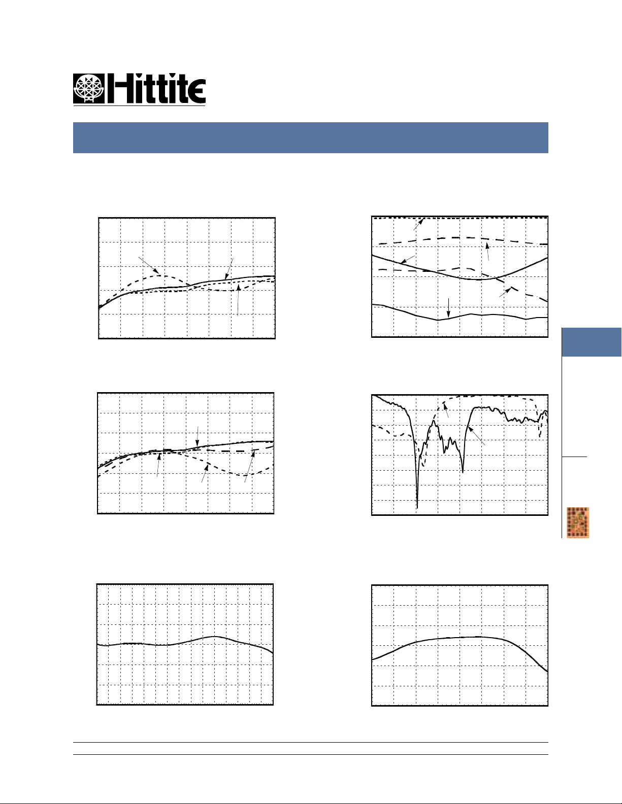
Conversion Gain vs. Temperature
@ LO = +15 dBm
0
-5
-10
-15
CONVERSION GAIN (dB)
-20
-25
24 26 28 30 32 34 36 38 40
-55 C
RF FREQUENCY(GHz)
+25 C
+85 C
Conversion Gain vs. LO Drive
0
-5
-10
-15
-20
CONVERSION GAIN (dB)
-25
-30
24 26 28 30 32 34 36 38 40
+16 dBm
RF FREQUENCY(GHz)
+15 dBm
+13 dBm
+14 dBm
Isolation @ LO = +15 dBm
0
RF/LO
-20
-40
ISOLATION (dB)
-60
-80
24 26 28 30 32 34 36 38 40
RF/IF
2LO/IF
RF FREQUENCY (GHz)
LO/IF
2LO/RF
Return Loss @ LO = +15 dBm
0
-5
-10
-15
-20
-25
RETURN LOSS(dB)
-30
-35
-40
0 5 10 15 20 25 30 35 40
IF
LO & RF
FREQUENCY (GHz)
4
MIXERS
DIE
Upconverter Performance
IF Bandwidth @ LO =+15dBm
0
-5
-10
-15
-20
IF CONVERSION GAIN (dB)
-25
-30
0 1 2 3 4 5 6 7 8 9 10 11 12 13 14 15
IF FREQUENCY (GHz)
12 Elizabeth Drive, Chelmsford, MA 01824 Phone: 978-250-3343 Fax: 978-250-3373 Web Site: www.hittite.com
Conversion Gain @ LO = +15dBm
0
-5
-10
-15
-20
CONVERSION GAIN (dB)
-25
-30
24 26 28 30 32 34 36 38 40
RF FREQUENCY (GHz)
4 - 113
 Loading...