

hittite HMC244G16 User Manual
查询HMC244G16供应商
14
MICROWAVE CORPORATION
Typical Applications
The HMC244G16 is ideal for:
• Telecom Infrastructure
• Military Radios, Radar & ECM
• Space Applications
• Test Instrumentation
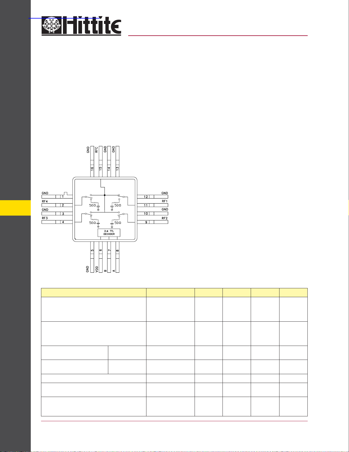
Functional Diagram
v01.0404
HMC244G16
GaAs MMIC SP4T NON-REFLECTIVE
SWITCH, DC - 4.0 GHz
Features
Low Insertion Loss: 0.7 dB
Non-Refl ective Design
Integrated 2:4 TTL Decoder
Single Positive Suppy: Vdd = +5V
16 Lead Hermetic SMT Package
General Description
The HMC244G16 is a non-refl ective SP4T switch in
a 16 lead glass/metal (hermetic) package. Covering
DC to 4.0 GHz, the switch offers 30~50 dB isolation
and a low insertion loss of 0.7 dB through 3 GHz. A
2:4 TTL/CMOS compatable decoder is integrated on
the switch requiring only 2 control lines and a positive 5V bias to select each path, replacing 8 control
lines normally required by GaAs SP4T switches.
Electrical Specifi cations, T
Insertion Loss
SWITCHES - SMT
Isolation
Return Loss “On State”
Return Loss RF 1 -4 “Off State”
Input Power for 1 dB Compression 0.5 - 4.0 GHz 21 25 dBm
Input Third Order Intercept
(Two-Tone Input Power = +7 dBm Each Tone)
Switching Characteristics
tRISE, tFALL (10/90% RF)
tON, tOFF (50% CTL to 10/90% RF)
14 - 128
= +25° C, With 0/+5V Control, 50 Ohm System
A
Parameter Frequency Min. Typ. Max. Units
DC - 1.0 GHz
DC - 3.0 GHz
DC - 3.5 GHz
DC - 4.0 GHz
DC - 1.0 GHz
DC - 2.0 GHz
DC - 3.0 GHz
DC - 4.0 GHz
DC - 3.5 GHz
DC - 4.0 GHz
0.2 - 4.0 GHz
0.5 - 4.0 GHz
0.5 - 3.0 GHz
0.5 - 4.0 GHz
DC - 4.0 GHz 40
40
36
30
24
43
40
0.6
0.7
1.0
1.4
45
40
35
28
18
13
10
15
47
43
150
0.9
1.0
1.4
1.8
For price, delivery, and to place orders, please contact Hittite Microwave Corporation:
12 Elizabeth Drive, Chelmsford, MA 01824 Phone: 978-250-3343 Fax: 978-250-3373
Order Online at www.hittite.com
dB
dB
dB
dB
dB
dB
dB
dB
dB
dB
dB
dB
dBm
dBm
ns
ns
v01.0404
HMC244G16
MICROWAVE CORPORATION
GaAs MMIC SP4T NON-REFLECTIVE
SWITCH, DC - 4.0 GHz
GaAs MMIC SUB-HARMONICALLY PUMPED MIXER 17 - 25 GHz
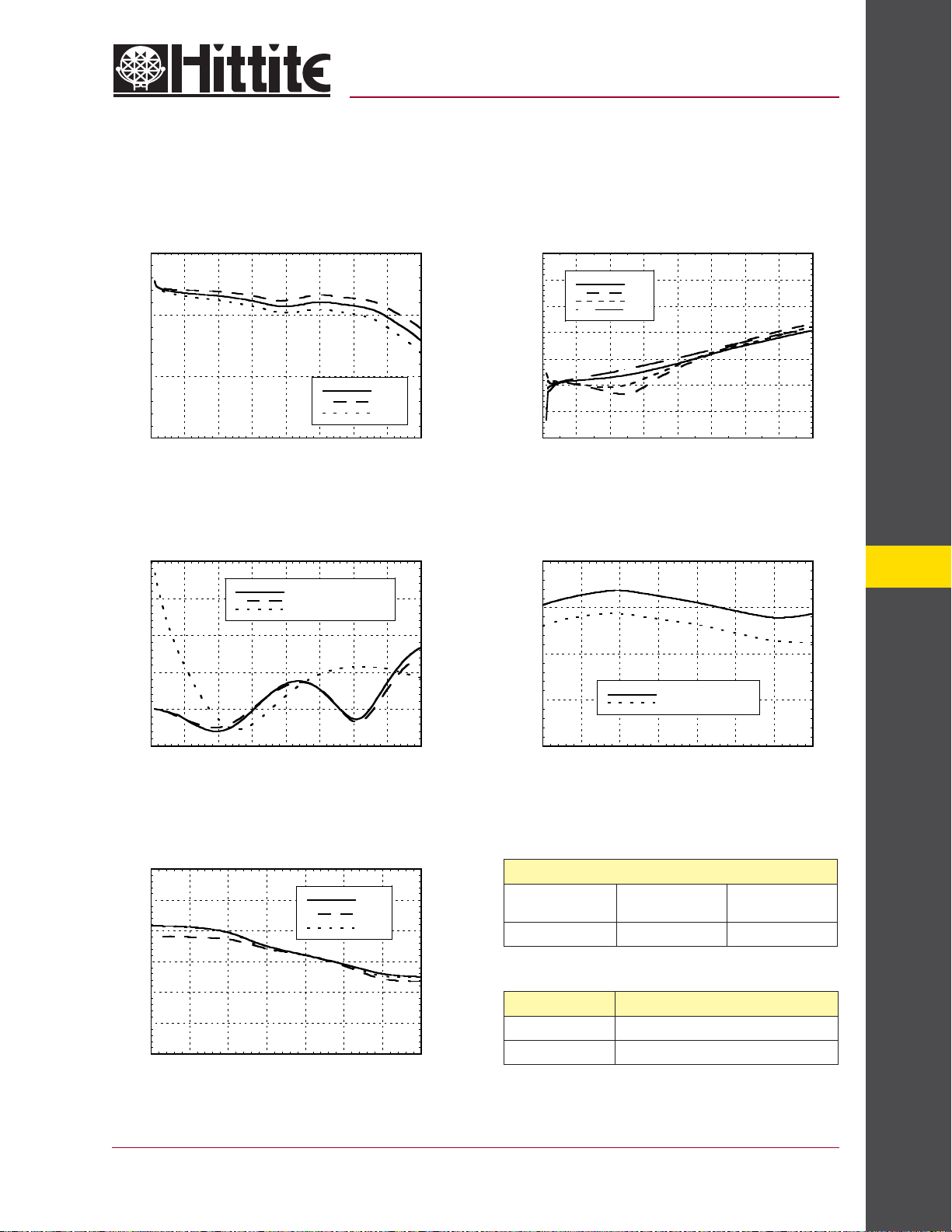
Insertion Loss Isolation
0
-1
-2
INSERTION LOSS (dB)
-3
0 0.5 1 1.5 2 2.5 3 3.5 4
FREQUENCY (GHz)
+ 25C
- 40C
+ 85C
0
-10
-20
-30
-40
ISOLATION (dB)
-50
-60
-70
0 0.5 1 1.5 2 2.5 3 3.5 4
RF1
RF2
RF3
RF4
FREQUENCY (GHz)
Return Loss 0.1 and 1 dB Input Compression Point
0
-5
-10
-15
RETURN LOSS (dB)
-20
RFC
RF1, RF2, RF3, RF4 ON
RF1, RF2, RF3, RF4 OFF
30
25
20
INPUT P1dB (dBm)
15
1 dB COMPRESSION
0.1 dB COMPRESSION
14
-25
0 0.5 1 1.5 2 2.5 3 3.5 4
FREQUENCY (GHz)
Input Third Order Intercept Point
60
55
50
45
40
INPUT IP3 (dBm)
35
30
0.5 1 1.5 2 2.5 3 3.5 4
FREQUENCY (GHz)
For price, delivery, and to place orders, please contact Hittite Microwave Corporation:
12 Elizabeth Drive, Chelmsford, MA 01824 Phone: 978-250-3343 Fax: 978-250-3373
+ 25C
+ 85C
- 40C
10
0.5 1 1.5 2 2.5 3 3.5 4
Bias Voltage & Current
Vdd
(Vdc)
+5.0 3.0 7.0
TTL/CMOS Control Voltages
State Bias Condition
Low 0 to +0.8 Vdc @ 5 uA Typ.
High +2.0 to +5.0 Vdc @ 70 uA Typ.
Order Online at www.hittite.com
FREQUENCY (GHz)
Vdd Range= +5.0 Vdc ±10%
Idd (Typ)
(mA)
SWITCHES - SMT
Idd (Max)
(mA)
14 - 129
 Loading...