

hittite HMC240 User Manual
查询HMC240供应商
7
MICROWAVE CORPORATION
Typical Applications
The HMC240 is ideal for:
• Telecom Infrastructure
• Microwave Radio & VSAT
• Military & Space
• Test Instrumentation
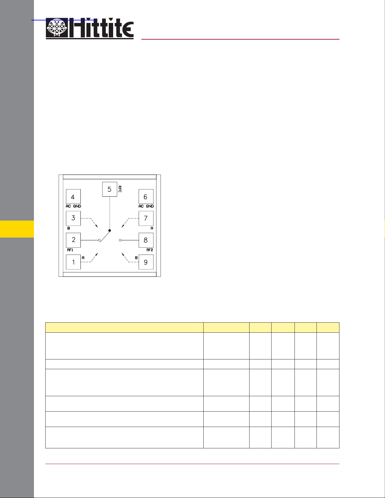
Functional Diagram
v00.0403
HMC240
GaAs MMIC SPDT SWITCH
DC - 4.0 GHz
Features
Broadband Performance: DC - 4.0 GHz
Low Insertion Loss: 0.5 dB @ 2.0 GHz
High IIP3: +48 dBm
Small Size: 0.70 mm x 0.70 mm x 0.13 mm
General Description
The HMC240 is a low cost GaAs MESFET SPDT
switch chip. Cov ering DC to 4.0 GHz, this s witch
offers high isolation and low insertion loss. RF1
and RF2 are refl ective shorts when “off”. The
switch can operate using either two negativ e control logic inputs of -5/0V or two positive control
voltage logic inputs of 0/+5V. All data is tested
with the chip in a 50 Ohm test fi xture connected
via 0.025 mm (1 mil) diameter wire bonds of 0.31
mm (12 mils) length.
Pads 3 & 7 are alternate A & B Control Inputs.
Electrical Specifi cations, T
With 0/-5V Control or +5/0V Control, 50 Ohm System
Parameter Frequency Min. Typ. Max. Units
Insertion Loss
SWITCHES - CHIP
Isolation DC - 4.0 GHz 24 28 dB
Return Loss “On State”
Input Power for 1 dB Compression
Input Third Order Intercept
(Two-Tone Input Power= +7 dBm Each Tone)
Switching Characteristics
tRISE, tFALL (10/90% RF)
tON, tOFF (50% CTL to 10/90% RF)
= +25° C,
A
DC - 1.0 GHz
DC - 2.0 GHz
DC - 3.0 GHz
DC - 4.0 GHz
DC - 1.0 GHz
DC - 2.0 GHz
DC - 3.0 GHz
DC - 4.0 GHz
0.5 - 1.0 GHz
0.5 - 4.0 GHz
0.5 - 1.0 GHz
0.5 - 4.0 GHz
DC - 4.0 GHz
0.4
0.5
0.6
0.9
22
16
14
11
25
23
43
40
30
29
48
45
3
10
0.7
0.8
0.9
1.4
dB
dB
dB
dB
dB
dB
dB
dB
dBm
dBm
dBm
dBm
ns
ns
7 - 8
For price, delivery, and to place orders, please contact Hittite Microwave Corporation:
12 Elizabeth Drive, Chelmsford, MA 01824 Phone: 978-250-3343 Fax: 978-250-3373
Order Online at www.hittite.com

v00.0403
HMC240
MICROWAVE CORPORATION
GaAs MMIC SPDT SWITCH
DC - 4.0 GHz
GaAs MMIC SUB-HARMONICALLY PUMPED MIXER 17 - 25 GHz
Insertion Loss vs. Temperature Isolation
0
-0.5
-1
-1.5
-2
INSERTION LOSS (dB)
-2.5
-3
0 0.5 1 1.5 2 2.5 3 3.5 4
+25 C
+85 C
-55 C
FREQUENCY (GHz)
Return Loss 0.1 and 1 dB Input Compression Point
0
-5
-10
-15
-20
RETURN LOSS (dB)
-25
-30
0 0.5 1 1.5 2 2.5 3 3.5 4
RFC
RF1, RF2, ON
FREQUENCY (GHz)
0
-5
-10
-15
-20
-25
-30
ISOLATION (dB)
-35
-40
-45
-50
0 0.5 1 1.5 2 2.5 3 3.5 4
32
31
30
29
28
27
26
25
INPUT P1dB (dBm)
24
23
22
0.5 1 1.5 2 2.5 3 3.5 4
RF1
RF2
FREQUENCY (GHz)
1.0 dB Compression Point
0.1 dB Compression Point
FREQUENCY (GHz)
7
Input Third Order Intercept Point
60
55
50
45
40
INPUT IP3 (dBm)
35
30
0.5 1 1.5 2 2.5 3 3.5 4
For price, delivery, and to place orders, please contact Hittite Microwave Corporation:
12 Elizabeth Drive, Chelmsford, MA 01824 Phone: 978-250-3343 Fax: 978-250-3373
Order Online at www.hittite.com
+25 C
+85 C
-40 C
FREQUENCY (GHz)
SWITCHES - CHIP
7 - 9
 Loading...