

hittite HMC183QS24 User Manual

查询HMC183QS24供应商
14
MICROWAVE CORPORATION
Typical Applications
The HMC183QS24 is ideal for:
• Basestation Infrastructure
Functional Diagram
v01.0101
HMC183QS24
GaAs MMIC SP8T NON-REFLECTIVE
SWITCH, DC - 2.0 GHz
Features
Low Insertion Loss (1 GHz): 0.8dB
Integrated 3:8 Decoder
24 Lead QSOP Package
General Description
The HMC183QS24 is a low-cost non-refl ective
SP8T switch in a 24-lead QSOP package for use
in antenna diversity, switched fi lter banks, gain/
attenuation selection, and general channel multiplexing applications. A 3:8 decoder is integrated on the switch, requiring only 3 control lines
with a negative bias to select an RF path. The
3:8 decoder replaces 16 control lines normally
required by GaAs SP8T switches. Switch outputs
are terminated when “off”. The QSOP24 package occupies the same area as a 14-lead SOIC.
See positive bias/TTL version HMC253QS24.
Electrical Specifi cations,
TA = +25° C, For 0/-5V Control and Vee = -5V in a 50 Ohm System
Insertion Loss
Isolation
SWITCHES - SMT
Return Loss RFC
Return Loss
Input Power for 1 dB Compression
Input Third Order Intercept
(Two-Tone Input Power = +7 dBm Each Tone)
Switching Characteristics DC - 2.0 GHz
Parameter Frequency Min. Typ. Max. Units
RF 1-8
‘ON’ and ‘OFF’
tRISE, tFALL (10/90% RF)
tON, tOFF (50% CTL to 10/90% RF)
DC - 1.0 GHz
DC - 1.5 GHz
DC - 2.0 GHz
DC - 0.5 GHz
DC - 1.0 GHz
DC - 1.5 GHz
DC - 2.0 GHz
DC - 1.0 GHz
DC - 1.5 GHz
DC - 2.0 GHz
DC - 1.0 GHz
DC - 1.5 GHz
DC - 2.0 GHz
50 MHz
0.5 - 2.0 GHz
50 MHz
0.5 - 2.0 GHz
38
32
29
26
16
10
7
12
10
10
30
37
0.8
1.0
1.3
42
36
33
30
20
14
11
15
13
13
18
20
35
42
35
50
1.2
1.5
1.8
dB
dB
dB
dB
dB
dB
dB
dB
dB
dB
dB
dB
dB
dBm
dBm
dBm
dBm
ns
ns
14 - 32
For price, delivery, and to place orders, please contact Hittite Microwave Corporation:
12 Elizabeth Drive, Chelmsford, MA 01824 Phone: 978-250-3343 Fax: 978-250-3373
Order Online at www.hittite.com
v01.0101
HMC183QS24
MICROWAVE CORPORATION
GaAs MMIC SP8T NON-REFLECTIVE
SWITCH, DC - 2.0 GHz
GaAs MMIC SUB-HARMONICALLY PUMPED MIXER 17 - 25 GHz
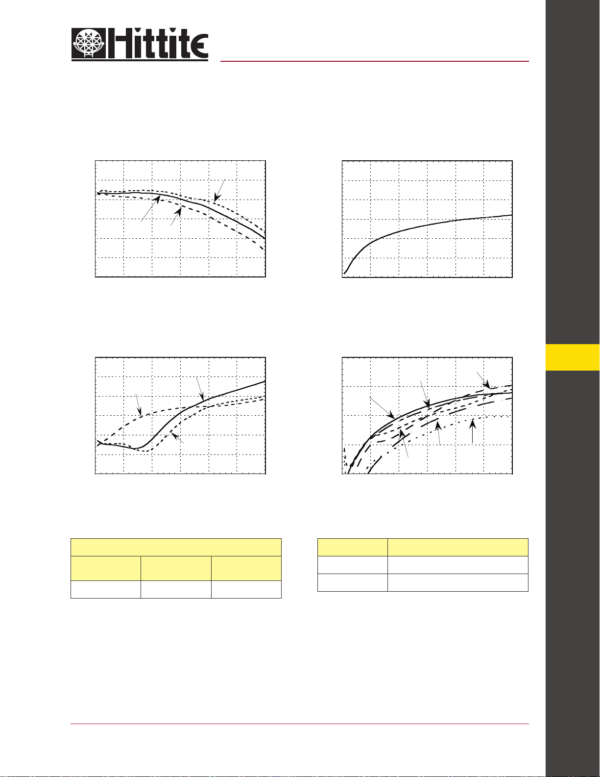
Insertion Loss
Isolation
0
-0.5
-1
-1.5
-2
INSERTION LOSS (dB)
-2.5
-3
0 0.5 1 1.5 2 2.5 3
+25 C
FREQUENCY (GHz)
+85 C
Return Loss
0
-5
-10
-15
-20
RETURN LOSS (dB)
-25
-30
0 0.5 1 1.5 2 2.5 3
S22 "Off"
FREQUENCY (GHz)
S11 RFC
S22 "On"
-40 C
0
-10
-20
-30
-40
ISOLATION (dB)
-50
-60
0 0.5 1 1.5 2 2.5 3
Isolation Between Several RF l/Os
-20
RF7-6
-30
RF8-7
-40
ISOLATION (dB)
-50
RF3-2
RF4-3
-60
0 0.5 1 1.5 2 2.5 3
FREQUENCY (GHz)
RF5-4
RF2-1
14
Bias Voltage & Current Control Voltages
Vee Range = -5.0 Vdc ± 10%
Vee
(Vdc)
-5.0 6.0 9.0
Iee (Typ.)
(mA)
Iee (Max.)
(mA)
For price, delivery, and to place orders, please contact Hittite Microwave Corporation:
12 Elizabeth Drive, Chelmsford, MA 01824 Phone: 978-250-3343 Fax: 978-250-3373
Order Online at www.hittite.com
State Bias Condition
Low 0 to -3 VDC 2 70 uA Typ.
High -5 to -4.2 VDC @ 5 uA Typ.
SWITCHES - SMT
14 - 33
 Loading...