

Hittite HMC137 Datasheet
MICROWAVE CORPORATION
GaAS MMIC BI-PHASE MODULATOR 6 - 11 GHz
HMC137
5
MODULATORS
DIE
FEBRUARY 2001
Features
CHIP INTEGRATES DIRECTLY INTO MIC DESIGNS
20 dB OF CARRIER SUPPRESSION
DIRECT MODULATION IN THE 6-11 GHz BAND
FUNCTIONS ALSO AS A PHASE DETECTOR
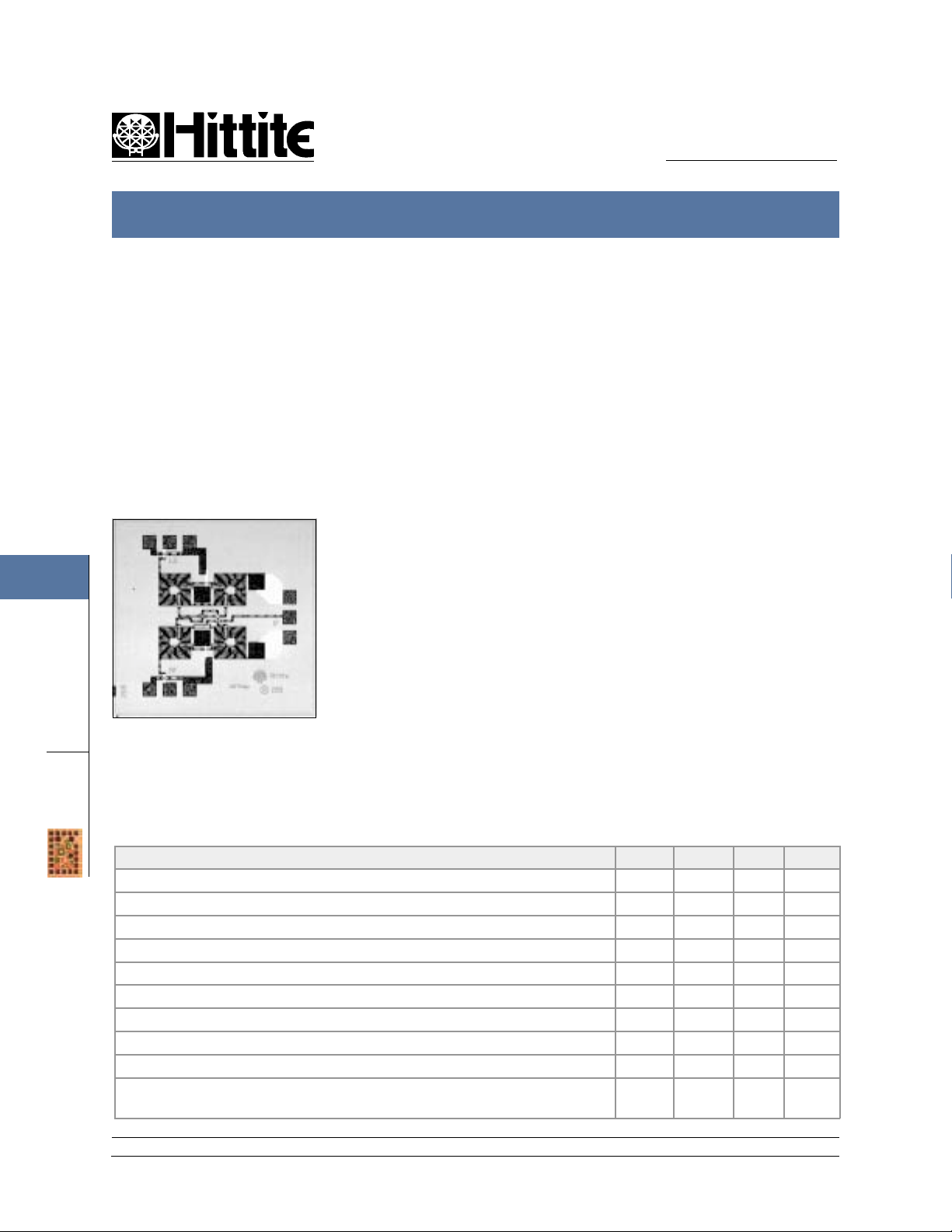
General Description
The HMC137 Bi-Phase Modulator is designed
to phase-modulate an RF signal into reference
and 180 degree states. Device input is at the RF
port and output is at the LO port. The polarity of
the bias current at the control port (IF port)
defines the phase states. Excellent amplitude
and phase balance provided by closely matched
monolithic balun and diode circuits delivers 20
dB of carrier suppression in a tiny monolithic
chip.
The device also functions as a demodulator or
phase comparator. As a demodulator, data
emerges at the control port when a modulated
signal at the RF port is compared to a reference
signal at the LO port. As a phase comparator,
the phase angle between two signals applied to
the RF and LO ports is represented by an analog
voltage at the control port.
Except for carrier suppression, the data presented here was measured under static conditions in which a DC bias current (nominally 5
mA) is applied to the control port.
V01.0300
Guaranteed Perf ormance, For 5mA Bias Current, -55 to +85 deg C
Parameter Min. Typ. Max. Units
Frequency Band 6-11 GHz
Insertion Loss 911dB
Return Loss, RF and LO Ports 2.5 3.0 dB
Amplitude Balance 0.25 0.50 dB
Phase Balance 10 15 deg
Carrier Suppression (When driven with a 1 MHz square wave, 1.4 Vp-p) 15 20 dBc
Input Pow er for 1 dB Compression 4 8 dBm
Third Order In tercept, Input 10 15 dBm
Second Order Intercept, Input 25 40 dBm
Bias C urrent (Bias current forward biases internal Schottky diodes
providing approximately 0.6 V at the control port).
2510mA
12 Elizabeth Drive, Chelmsford, MA 01824 Phone: 978-250-3343 Fax: 978-250-3373 Web Site: www.hittite.com
5 - 10
MICROWAVE CORPORATION
HMC137 BI-PHASE MODULATOR 6 - 11 GHz
HMC137
V01.0300
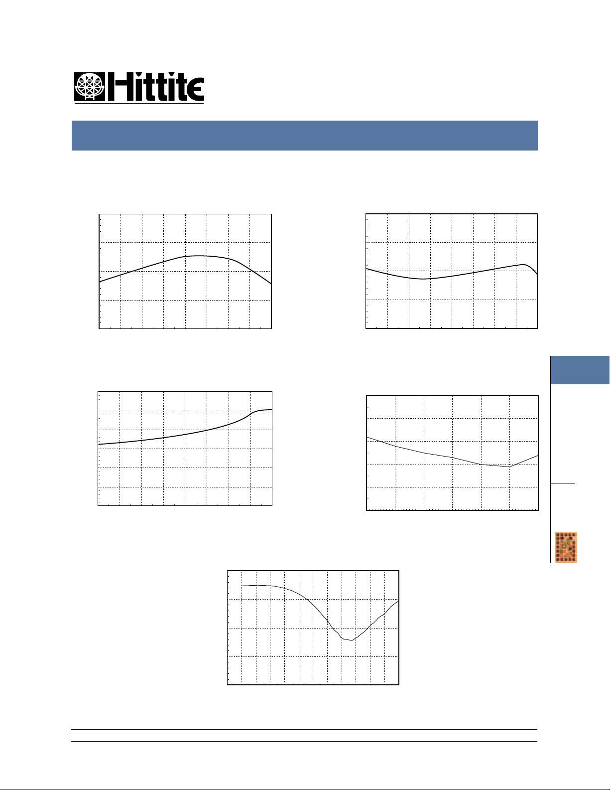
Insertion Loss
0
-5
-10
-15
INSERTION LOSS (dB)
-20
4 5 6 7 8 9 10 11 12
FREQUENCY (GHz)
Phase Balance
15
10
5
0
-5
FEBRUARY 2001
Amplitude Balance
2
1
0
-1
AMPLITUDE BALANCE (dB)
-2
456789101112
FREQUENCY (GHz)
Carrier Suppression
(For 1.4 V p-p Square Wave Modulation at 1 MHz)
50
40
30
20
5
MODULATORS
PHASE BALANCE (Deg)
-10
-15
456789101112
FREQUENCY (GHz)
10
0
CARRIER SUPPRESSION (dBc)
6789101112
CARRIER FREQUENCY (GHz)
Return Loss
0
-5
-10
-15
RETURN LOSS (dB)
-20
2 3 4 5 6 7 8 9 10 11 12 13 14
FREQUENCY (GHz)
12 Elizabeth Drive, Chelmsford, MA 01824 Phone: 978-250-3343 Fax: 978-250-3373 Web Site: www.hittite.com
5 - 11
DIE
 Loading...