

Page 1

15-0 4-22
15-0 4-22
15-0 4-22
15-0 4-22
B
50303712
M.J .KWON
HCG(I)-P7xDxA32/NoBrand(Effio-A)
50303712
M.J. KWON
03-0 3-M14
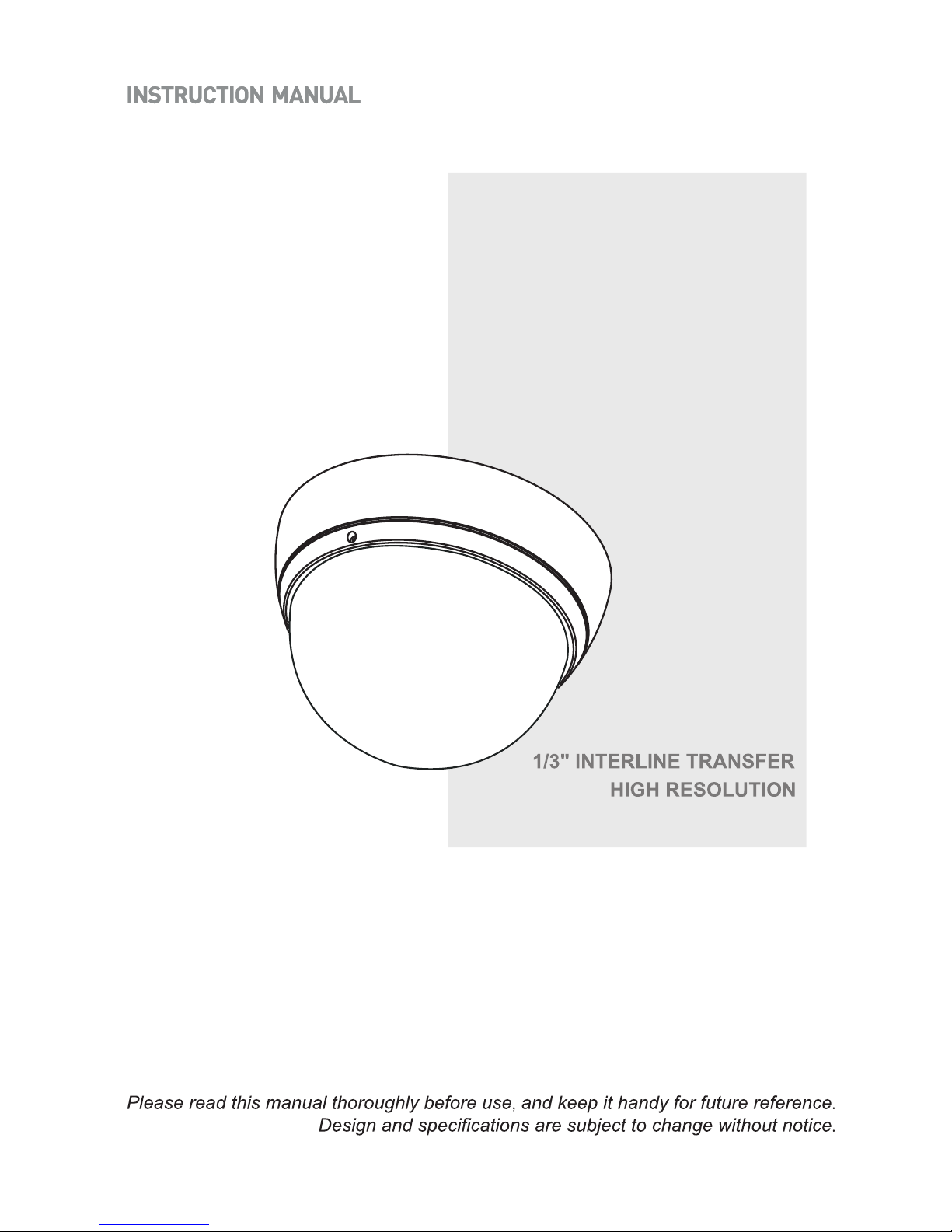
Super High
Resolution
Day & Night
Camera
50303712
M.J. KWON
15-0 4-22
B
rev.B -5p:Va rious D etect ion Met hods 수정
Page 2
Super High
Resolution
Day & Night
Camera
Page 3

FCC COMPLIANCE STATEMENT
CE COMPLIANCE STATEMENT
CAUTION : Changes or modifications not expressly approved by the party responsible for
compliance could void the user’s authority to operate the equipment.
This device complies with Part 15 of the FCC Rules. Operation is subject to the following two
conditions: (1) this device may not cause harmful interference, and (2) this device must
accept any interference received, including interference that may cause undesired operation.
WARNING : This is a Class A poduct. In a domestic environment this product may cause
radio interference in which case the user may be required to take adequate measures.
FCC INFORMATION : This equipment has been tested and found to comply with the limits
for a Class A digital device, pursuant to Part 15 of the FCC Rules. These limits are designed
to provide reasonable protection against harmful interference when the equipment is
operated in a commercial environment. This equipment generates, uses, and can radiate
radio frequency energy and, if not installed and used in accordance with the instruction
manual, may cause harmful interference to radio communications. Operation of this
equipment in a residential area is likely to cause harmful interference in which case the user
will be required to correct the interference at his own expense.
2
Page 4
1. Read these instructions.
2. Keep these instructions.
3. Heed all warnings.
4. Follow all instructions.
5.. Do not block any ventilat ion openings. Install in accord ance with the manufacturer`s
instructions.
6. Do not install near any heat sources such as radiators, heat registers, stoves, or other
apparatus (including amplifiers) that produce heat.
7. Only use attachments/accessories specified by the manufacturer.
8. Use only with the ca rt, stand, tripod, bracket, or table specified by
the manufacturer, or sold with the apparatus. When a cart is used,
use caution when moving the cart/ apparatus combination to avoid
injury from tip-over.
9. CAUTION - THESE SERVICING IN STRUCTIONS ARE FOR USE BY
QUALIFIED SERVICE PERSONNEL ONLY. TO REDUCE THE RISK OF
ELECTRIC SHOCK DO NOT PERFORM ANY SERVICING OTHER THAN
THAT CONTAINED IN THE OPERATING INSTRUCTIONS UNLESS YOU
ARE QUALIFIED TO DO SO.
10. Use satisfy clause 2.5 of IEC60950-1/UL 60950-1 or Certified/Listed Class 2
power source only.
11. Indoor use only.
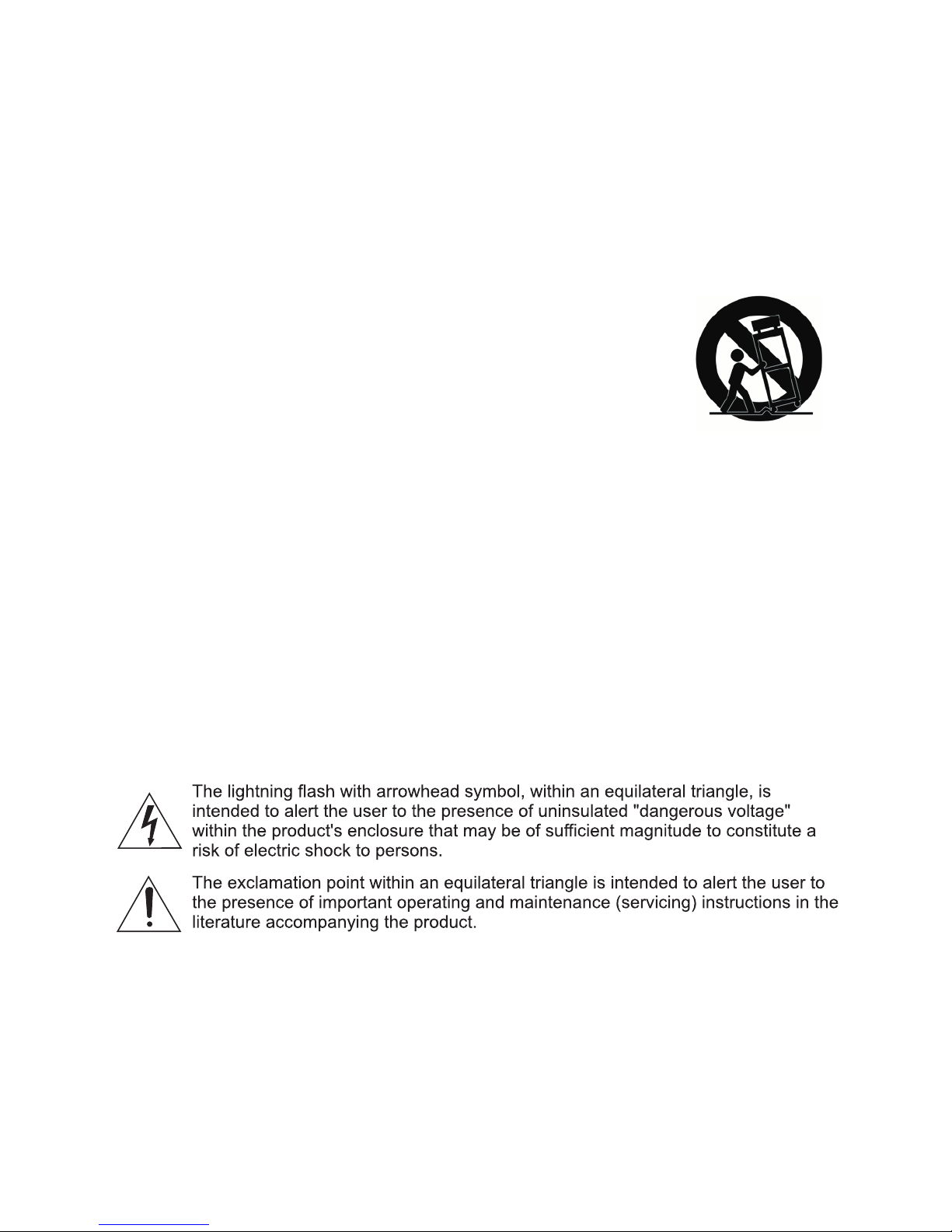
EXPLANATION OF GRAPHICAL SYMBOLS
IMPORTANT SAFETY INSTRUCTIONS
3
LIMITATION OF LIABILITY
THE INFORMATION IN THIS PUBLICATION IS BELIEVED TO BE ACCURATE IN ALL
RESPECTS, HOWEVER, WE CANNOT ASSUME RESPONSIBILITY FOR ANY
CONSEQUENCES RESULTING FROM THE USE THEREOF. THE INFORMATION
CONTAINED HEREIN IS SUBJECT TO CHANGE WITHOUT NOTICE. REVISIONS OR NEW
EDITIONS TO THIS PUBLICATION MAY BE ISSUED TO INCORPORATE SUCH CHANGES
Page 5

TABLE OF CONTENTS
CONNECTION & CONTENTS
6
INTRODUCTION
6
BASE INSTALLATION 7
MANU MAP 8
19
20
SPECIFICATIONS
4
DIMENSION
Page 6
5
The camera provides a high-quality image using SONY Wide Dynamic 1/3”
Super-HADII 960H CCD and digital signal processing LSI chips.
1/3" Super-HADII 960H CCD
Super high-resolution of 750TV lines
Auto Electronic Shutter [1/50(60) ~ 1/100,000] and manual electronic shutter modes
[1/50(60) ~ 1/10,000]
0.1 lux(Colour), 0.01 lux(B/W), 0.001 lux(Slow-Shutter) @ F1.4 Sensitivity
Digital Noise Reduction- 2D,3D
Day & Night(Auto, Day, Night)
Sens-Up (~x256)
Various Detection Methods (zone detection, motion trace)
Intelligent scene recognition - Provide the best image automatically for every scene
Mechanical iris auto adjustment
Privacy Mask or Mosaic (MAX. 15 area /4-point polygonal/transparency)
E-Zoom
White pixel detection and compensation
Digital Effect-FLIP (H/V reverse, inverse)
Defog(Auto) - Detects foggy condition automatically and
provides high contrast picture
IR Optimizer
Coaxial communication (Coaxitron by Pelco)
RS-485 Remote camera control(Pelco-D)-Option
Support Line-Lock external synchronization (Line lock) -Option
Operates in 12VDC or 24VAC-Option
Digital Wide Dynamic Range-ATR-EX2
Page 7
6
RS 485(+)
DN EXT-IN
AC24V/DC12V
AC24V/DC12V
RS 485 (-)
GRAY
BLACK GND
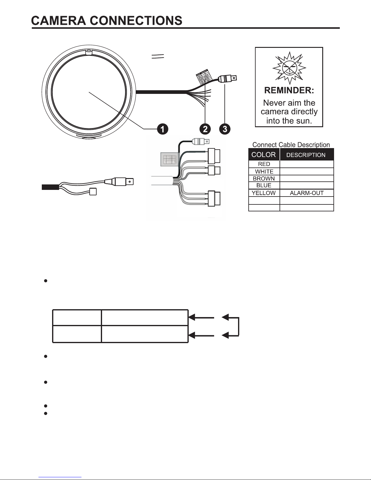
<Connector Option>
Select Day/Night mode using external equipment, by connecting control lines to the appropriate
terminals.
2-1. External Day/Night Control(Option)
DAY&NIGHT EXTERNAL INPUT
Switches the cameras D/N mode to either Day or Night based on the input status. Refer to the
diagram below. The cameras CNTL SIGNAL of D/N AUTO mode must be set to EXT2 for this
to function.
2-2. Alarm Out -Open Collector (5V/10mA)
2-4. Camera Control(Option)
BROWN : RS 485+
BLUE : RS 485-
2-3. Power Input Terminal
RED & WHITE : These terminals accept 24V AC or 12V DC. When using 12V DC it is
recommended to use a DC power supply that can support an inrush current of 0.55A
DAY&NIGHT INPUT
Gray
GND
Black
●
●
Close contact: NIGHT
Open contact: DAY
1. Lens : Allows a wide area to be monitored.
2. Color Lead Wire & Color Display Label
3. Video : BNC connector used to connect the camera to a monitor, swither, etc.
Motion detection signals are output through this port. Active state is Low(GND).
Normal : Open Collector, ALARM : Low(GND)
DC 12V Type
Page 8

Press here to adjust the angle.
1. Make mounting holes and cable hole in
the place (ceiling or wall) to which this
dome camera is installed using the
Driling guide label.
2. To remove dome cover, turn the dome
body counterclockwise until locators
reach and of travel and pull off.
Push the liner on the sides where the
patterns are put in the teeth of a comb
and pull it out.
3. Attach the housing to the ceiling using
suitable fasteners, M6x35 tapping screw
are supplied only if they are suitable.
Turn the housing to right direction about
16 degree to lock in place.
4. The assembly of the dome body and
liner is in reverse order of disassembly.
Finally, lock dome body with locking
screw(M3x5) from the accessory kit.
7
Page 9

MANU MAP
1/
2
SCENE SELECT
PICT ADJUST
EZOOM
DIS
PRIVACY MASK
MOTION DET
SYS SETTING
EXIT
SCENE SELECT
CUSTOM
FULL AUTO
INDOOR
OUTDOOR
BACKLIGHT
ITS
SETUP MANU
BRIGHTNESS
CONTRAST
SHARPNESS
HUE
COLOR GAIN
PICTURE ADJUST
MAG
PAN
TILT
EZOOM
SHUTTER/AGC
AUTO
MANUAL
FIX
WHITE BAL
ATW
PUSH
USER1
USER2
MANUAL
PUSH LOCK
ATR-EX
OFF
ATR-EX
DAY/NIGHT
AUTO
DAY
NIGHT
AUTO SETUP
AE LEVEL
AGC MAX
SENS UP
ATW SETUP
SPEED
DELAY CNT
ATW FLAME
ENVIRONMENT
ATR-EX SETUP
CONTRAST
CLEAR FACE
D/N AUTO SETUP
BURST
CNTL SIGNAL
DELAY CNT
DAY->NIGHT
NIGHT->DAY
IR OPTIMIZER SETUP
MODE
IR AREA
LEVEL
IR LED
COLOR NIGHT
IR SHADE COMP
RETURN
ADVANCE MENU
SHUTTER/AGC
WHITE BAL
HLC/BLC
WDR/ATR-EX
DNR
DAY/NIGHT
IR OPTIMIZER
RETURN
1/
2
IR AREA
TOP
BOTTOM
LEFT
RIGHT
WEGHT
IR LED
DAY/NIGHT
OFF
FIX
IR SHADE COMP SETUP
PATTERN
POSH
POSV
LEVEL
8
RETURN RETURN
RETURN RETURN
RETURN RETURNRETURN RETURN
Page 10

MANU MAP
ADVANCE MENU
LENS SHD COMP
DEFOG
FLK LESS
ANTI CR
2/
2
LENS SHADE
COMP SETUP
PATTERN
POSH
POSV
DEFOG SETUP
LEVEL
FLK LESS
AUTO
OFF
ON
ANTI CR
AUTO
OFF
ON
SCENE SELECT
PICT ADJUST
EZOOM
DIS
PRIVACY MASK
MOTION DET
SYS SETTING
EXIT
SETUP MANU
SYS SETTING
SYNC MODE
LENS
FLIP
LCD/CRT
COMMUNICATION
CAMERA ID
ENTRANCE
RETURN
DIS
OFF
ON
PRIVACY MASK
AREA SEL
DISPLY
POSITION
COLOR
TRANSP
MOSAIC
MOTION DET
DETECT SENSE
INTERVAL
BLOCK DISP
MASK AREA
MONITOR AREA
1/
2
MONITOR AREA
AREA SEL
AREA MODE
TOP
BOTTOM
LEFT
RIGHT
AUTO IRIS SETUP
MODE
ADJUST
SPEED
FLIP
OFF
V
H
HV
COMMUNICATION
PROTOCOL
ADDRESS
BAUDRATE
DATABIT
PARITY
STOPBIT
RETURN RETURN
RETURNRETURN RETURN
RETURN
RETURN RETURN
9
RETURN
Page 11

MANU MAP
LANGUAGE
VERSION
MAINTENANCE
EXIT
SETUP MANU
2/
2
LANGU AGE
ENGLISH
ESPANOL
PYCCKNN
PORTUGUES
DEUTSCH
FRANCAIS
日本 語
RETURN
MAINT ENA NCE
W.PIX MASK
CAMERA RESE T
W.PIX MA SK
AUTO
DATA CLEAR
MANUAL
MANUA L COMP
REGISTRATION
REG.POINT
CUSOR COLOR
BLINK
REG.NUMBER
AUTO C OMP
LEVEL1
LEVEL2
AUTO
RETURN
RETURN
RETURN
10
Page 12

<SETUP MENU>
The six modes can be selected.
CUSTOM /FULL AUTO / INDOOR / OUTDOOR / BACK LIGHT / ITS
CUSTOM
This mode turns off the auto scene recognition. All functions can be set and adjusted manually
FULL AUTO
This mode supports various shooting scenes. It is not specialized to any particular scene, so it
allows average shooting in any situation.
INDOOR
This mode is specialized to indoor scenes, such as indoor shop surveillance. It allows natural
shooting with high contrast.
OUTDOOR
This mode is specialized to outdoor scenes, such as road surveillance. It features high contrast
and resolution, and allows shooting with high visibility even in foggy outdoor conditions.
BACKLIGHT
This mode is specialized to scenes that mix indoor and outdoor conditions, such as entranceway
surveillance.
It allows shooting with high visibility and a high dynamic range, even under backlighting
conditions.
ITS
This mode is specialized to scenes where moving subjects enter the picture, such as traffic
surveillance scenes. It allows high-resolution shooting of moving subjects with low blur.
1. Scene Select function
2. Scene Select function
This Camera system provide functions that enable users to easily adjust the image quality to suit
the image output device used.
Brightness - Adjusts the brightness
Contrast - Adjusts the image contrast (light and shade differences).
Sharpness - Adjusts the apparent resolution
Hue - Adjusts the hue
Color Gain - Adjusts the intensity (brilliance) of the colors
3. EZOOM (Electronic Zoom)
EZoom - ON / OFF
MAG - Magnification rate = ZOOM (0~255)
PAN - Horizontal position settings
TILT -Vertical position settings
4. DIS (Digital Image Stabilizer)
Digital Image Stabilizer (DIS) function internally detects shaking of the image due to camera
shaking, and performs digital compensation processing inside the DSP to suppress this shaking
and stabilize the image output.
11
Page 13

12
5. PRIVACY MASK
The mask function hides one or more areas which the user does not want to be displayed on the
screen. This SET is capable of outputting 15 masks to the display. Each of these 15 masks can be
set with its own display area, color, darkness and mosaic processing.
AREA SEL - Select mask area (1-15).
DISPLAY - Mask to ON or OFF
POSITION
COLOR - Sets the color blend:
RED/ GREEN/ BLUE/ YELLOW/ CYAN/ MAGENTA/ WHITE/ BLACK
TRANSP - Sets the brightness blend ratio: 0%, /50%/75%/100%
MOSAIC - Sets the mosaic to ON or OFF.
6. MOTION DET (Motion Detection)
By using the motion detection function, it is possible to create surveillance cameras which are
capable of detecting moving objects. The motion detection function identifies motion and outputs
motion information when the difference in brightness exceeds a specific level between frames(2VD).
DETECT SENSE
Sets the motion detection threshold.
INTERVAL
Sets the MD detection interval. Subjects are detected when an interval exceeding the set number
of fields has elapsed from the previous motion detection.
BLOCK DISP
Motion detection result frame display selection
Outputs the results of the motion detected in each block
MASK AREA
MD (Motion Detection) setting menu, for setting the no-detection area.
The active point (MASK AREA 1~96)is displayed. Move the point with 4-arrow keys.
Press[ENTER] key is to finish edit point. (No-detection area)
MONITOR AREA
Sets the position of the monitoring frames in pixel or line increments
7. SYS SETTING
7-1. SYNC MODE (OPTION)
External synchronization is a function with synchronization of the phase between an output video
signal and an external reference signal. Use line lock mode to minimize color rolling.
INT
In this mode, synchronization is not implemented with a multiple number of cameras.
LL
In this mode, PLL is used to synchronize the vertical sync signal with the AC power supply with a
power line frequency of 60 Hz (for the NTSC format) or 50 Hz (for the PAL format).
PHASE -External synchronization phase adjustment.(LL)
Note: LLC can only be used when AC power is used.
LL of DC power input state, IC operates internally(INT).
7-2. LENS
Set the lens type
AUTO Select the Lens DC Iris type
Manual Select the Lens Manual type
7-2-1. MODE
AUTO This mode controls the iris in accordance with the subject brightness.
OPEN This mode fully opens the iris.
CLOSE This mode fully closes the iris.
Page 14

7-2-2. ADJUST
When performing the automatic mechanical iris adjustments, the convergence speed which is
suitable for the lens installed is calculated, Shoot a high-brightness subject which will make the
brightness of the whole screen uniform.
-Check that the shooting conditions are sufficiently bright and stable.
7-2-3. SPEED
Sets the convergence speed.
7-3. FLIP
Select digital Flip / Rotate state
Off / V(Top / bottom reversal) / H(Left / right reversal) / HV(Rotation by 180 degrees)
7-4. LCD / CRT
Seclect Monitor mode.
7-5. COMMUNICATION (OPTION)
Communication using the RS-485 format.(Option)
Press the Enter button to access the Communication.
Protocol - RS-485 protocol. (PELCO-D)
ADDRESS - Select the camera ID. (001 - 255)
Baud Rate - Select serial communication speed. (2400 / 4800 / 9600 / 19200)
Note. Key of Keyboard Controller
MENU Joystick Handle turn clockwise , ZOOM TELE
ENTER Joystick Handle turn clockwise, IRIS CLOSE
OSD Cursor Movement Joystick Up / Down / Left / Right
7-6. CAMERA ID
CAMERA ID SETUP.
SAVE Save the settings (settings are saved)
NOT SAVE Exit
Menu without saving SAVE : Exit menu without saving.
CANCEL Changes (restore settings to those selected when the menu was displayed)
BACK Return to previous menu
RETURN Return to page on the hierarchical level immediately before.
8. EXIT-MENU
CAMERA ID
CAMERA ID
ABCDEFGHIJKLMNOPQRSTUVWXYZ
0123456789`~!@#$%^&*()-_=+<,>.?/;:’”
CLR POS
RETURN
CLR
Inserts a space
POS
Allows you adjust the location of the camera ID title display. (if you move too
much right side or down, it might lose ID on the screen)
Sets the camera ID to ON or OFF. A title of 64
Characters per line can be applied.
Use the joystick to navigate the cursor.
Pushing centrally on the joystick will allow selection
of that character.
The arrows at the bottom allow you to move the
cursor without changing the character.
13
Page 15

W.PIX MASK
White pixel compensation menu. The white pixel detection and compensation function can
automatically detect and compensate up to 64 white pixels.(Static detection)
AUTO
This mode performs the optimal operation for detecting white pixels, and automatically detects the
white pixels of CCD image sensors.
LEVEL1 - Normal Defect
The threshold adjustment of the white pixel detection
LEVEL2 - Large Defect
The threshold adjustment of the very large white pixel detection
AUTO Press Enter button to turn White Pixel Compensation mode Start.
RUN Press Enter button to start White Pixel Compensation start.
RUNNING Process to find white pixel.
SBC SUCCESS Process ended.
MANUAL
- REGISTRATION
Manual white pixel defect information registration
1) Press the Enter button to turn White pixel compensation position marker display.
2) Use the Arrow buttons align the marker with the position of the white pixel.
3) Press the Enter button to exit and Press the EXIT button to save.
Note : In manual detection mode, the detection data is always treated as a very large white
pixel. Up to 64 white pixel compensation.
- NEXT REGISTRATION
Continue with manual white pixel compensation settings
- REG.POINT
Selects whether to display the registered White or Black pixels
- CURSOR COLOR
Cursor color during manual defect registration
- BLINK
Cursor display blinking during manual defect registration
- REG.NUMBER
Registered white pixel defect count display
- DATA CLEAR
Initializes the white pixel compensation information
Select erasing white pixel function to press Enter button (YES)
11. MAINTENANCE
9. LANGUAGE
10. VERSION
LANGUAGE select between:
English, Spanish, Russian, Portuguese, German, French, Japanese.
Camera version information.
14
Page 16

<ADVANCED MENU>
AEME (Auto Exposure / Manual Exposure) selection, shutter / AGC
This type of control adjusts the exposure amount using the shutter speed.
12-1. AUTO
Exposure control is performed automatically.
AE LEVEL (Auto Exposure Lebel)
AE performs exposure control so that the OPD output level (evaluation value) is the target
brightness level (AE reference level). This control is called AE gain control.
AGC MAX
Maximum gain setting item in shutter priority mode AGC (Auto Gain Control)
This type of control adjusts the exposure amount during CCD signal input by applying AFE gain
SENS UP (Slow Shutter)
Low-brightness sensitivity enhancement menu
Select maximum Slow-Shutter (AUTO and Off)
12-2. MANUAL
Exposure control is performed manually.
12-3. FIX
Exposure control is stopped. AE does not track even if the subject brightness changes.
12. SHUTTER / AGC
Compensates for deviations in the white colour caused by changes in the colour temperature of
the light source so that the colours are reproduced correctly.
ATW - ATW mode (1800ºK ~10500ºK)
Performs indoor / outdoor identification, estimates the light source, and performs WB control
automatically.
Push (Full pull-in)
This control is resistant to the effects of deeply colored subjects. The PUSH function performs WB
control automatically regardless of the indoor/outdoor and light source conditions. Compensation
may be performed incorrectly since this control is easily affected by deeply colored subjects.
USER1
The USER1 functions set the WB gain in accordance with preset values. (3200ºK)
WB control does not track even if the subject color temperature changes.
Adjust red or blue gain.
R(R-GAIN):Adjust R-GAIN value (0-255)
B(B-GAIN):Adjust B-GAIN value (0-255)
USER2
The USER2 functions set the WB gain in accordance with preset values. (5800ºK)
WB control does not track even if the subject color temperature changes.
Adjust red or blue gain.
R(R-GAIN):Adjust R-GAIN value (0-255)
B(B-GAIN):Adjust B-GAIN value (0-255)
13. WHITE BAL
15
Page 17

16
MANUAL
MWB allows WB control to be performed manually following the black body radiation curve.
The configurable color temperature setting range is 1500K to 15000K. The setting can be
performed in 64 steps.
PUSH LOCK
Holds the all pull-in frame The PUSH LOCK function first transfers to PUSH mode and performs
pull-in operation, and then transfers to HOLD mode when pull-in is complete.
14. HLC / BLC
HLC (Highlight Compensation)
HLC luminance signal processing is a function that suppresses or masks the luminance signal. It
reduces the load on watchers' eyes and enhances visibility impaired by strong light sources or
other factors by performing output while suppressing the brightness of high-brightness areas.
CLIP LEVEL HLC mask level
BLC (Backlight Compensation)
The BLC function provides compensation by increasing the brightness of the overall screen so
that subjects being shot with a loss of dark detail due to backlight will have just the right
brightness level.
CONTRAST(LOW/MID/HIGH) Contrast adjustment gain
CLEAR FACE(OFF/ LOW/MID/HIGH) High-frequency component adjustment gain
15.ATR-EX
ATR-EX(Extended)
The ATR function provides gradation compensation with the aim of improving visibility.
It compensates to the optimum gradation on the basis of the luminance information.
This function compresses the dynamic range while storing the contrast component of the subject.
Used to reduce image noise in order to improve the image quality of the camera.
It reduces the noise which is generated under low-light conditions and other high-gain states.
LEVEL Adjusts the NR (3D+2D) strength (0~6)
16. DNR
17-1 AUTO
Camera automatically switches between Day&Night modes according to the D>N & N>D levels.
BURST : Select B/W Burst On/Off
CNTL SIGNAL
Selection of brightness reference for identifying Day/Night Control Signal.
INT ILM levels
EXT1 external sensor inverting.
EXT2 external sensor non-inverting.
Ext : Camera switches between Day & Night modes according to the D/N EXT input.
(ILM level or GPI Cable)
Delay CNT : Adjust the judgment time for the transition between the Day and Night. (0-255).
DAY>NIGHT Level : Select switching level Day to Night (0-255).
NIGHT>DAY Level : Select switching level Night to Day (0-255)
Day : Camera stays in Day mode (Color)
Night : Camera stays in Night mode (B/W)
17. DAY/NIGHT
Page 18

17
If, when the Night operation mode of the Day/Night function is established, the mode is used
together with an external infrared LED light source, excessive front lighting may be generated,
resulting in overexposure.
18-1. IR OPTIMIZER SETUP
MODE(IR Model only)
IR optimizer photometry mode selection
IR AREA
IR optimizer judgment area setting menu in spot photometry mode
LEVEL
IR optimizer intensity(0~12)
IR LED(IR Model only)
OFF LED light level is LOW
FIX Adjust LED light level (0~255).
DAY/NIGHT LED light level determinate AE reference level
COLOR NIGHT
The Color Night Mode (CNM) function allows images to be taken as color images even with
infrared LED floodlighting under low-brightness conditions.
This Camera System feature a function that achieves both improved sensitivity and the ability to
reproduce colors under infrared LED floodlighting using signal processing that separates the
infrared LED light components from the images taken and extracts the original colors of the
subject. This function takes effect during Night operations.
COLOR GAIN LOW/MID/HIGH
18. IR OPTIMIZER (OPTION)
IR SHADE COMP (IR Model only)
The IR-SHD function compensates for observable events in which the light passing through the
lens is imaged non-uniformly.
Shading function ON/OFF selection
PATTERN
Selects the shape of the ellipse (HIGH/MID/LOW)
POSH / POSV
Use the center coordinate settings to adjust the shading compensation to the center position of
the optical axis.
LEVEL
The compensation level can be set to low, medium or high for basic shading compensation data.
19. LENS SHD COMP
The LENS SHD function compensates the lens is imaged non-uniformly.
PATTERN
Selects the shape of the ellipse (HIGH/MID/LOW)
POSH / POSV
Use the center coordinate settings to adjust the shading compensation to the center position of
the optical axis.
20. DEFOG
Defoging function ON/OFF selection. The defog function raises the contrast to improve visibility.
For example, in foggy conditions, contrast is reduced and visibility drops. In such cases, enabling
the defog function prevents a drop in contrast. In addition to compensating for contrast,
compensation is also made for the saturation, edges, and 3D-NR moving body identification
threshold. The defog compensation strength can be set to three levels (Low, Mid, High) using the
Auto function.
Page 19

18
21. FLK LESS
Flickerless function ON/OFF selection
MODE
GAIN CNTL Selects gain modulation ON.
SHUTTER FIX Selects flickerless shutter fix ON.
Anti color-rolling mode is valid when the AEME parameter is set to AE. When the parameter is set
to HOLD, the status of the previous field is maintained.
Users can select from the following anti color-rolling modes.
AUTO Anti color-rolling is automatically detect and compensate
ON Anti color-rolling is always compensate
OFF Anti color-rolling is not compensate
When the Auto anti color-rolling mode is selected, then the auto flickerless mode is turned on at
the same time.
22. ANTI CR (Anti color-rolling)
Recommendation Controller can communicate with camera through the BNC port.
Recommendation controller
Coaxial Remote Controller : RM-1000
*Note Coaxial Communication (32 Bit)
E.Enter
(N) to infinity( ).∞
Focal Length
Ape.Ratio
1/3" CCD
2.8~12mm 5%
1:1.4 5%
Image Size
Page 20

SPECIFICATIONS
19
Tact Switch, Coaxial COMM(32BIT),RS485(Pelco D)-Option
OFF/ATR-EX (LOW/MID/HIGH)
DC12V - 170mA(2.1W)
AC24V / - 180mA(2.2W)DC12V
(Option)
/ Line Lock(Option)
1/3" Super-HADII 960H CCD
1028(H)x508(V)
976(H)x494(V)Effective pixels
, 0.001Lux(Slow-shutter)
6~44.8DB
1/50-1/100,000 sec.(Auto)
Shutter Speed
BLC
OFF / HLC / BLC
750TVL
Alpha NumericCamera Title
DNR
2DNR, 3DNR : Gain Adjust
Auto / Day / Night
Privacy zone
Max 15 (Tilt, Colour, Transparency, Mosaic)
Effect V-Flip / Mirror / Rotation / Nega&Posi / Freeze / Sharpness
Sens-up OFF / AUTO
Sharpness
0~15 steps
DWDR
E-Zoom
Bad Pixel
LANGUAGE
MOTION
OFF / 0 ~ x255(E-Zoom) / PAN/TILT
AUTO/MANUAL/Done (M ax 64 point), Detected pixel display
English, Spanish., Russian, Portuguese, German,
French, Japanese(OPTION)
Detect Sense/Interval/B lock DISP/Mask Area/Monitor Area
.
IR Optimizer
OFF / ON
Lens DC / MANUAL
Scene Select CUSTOM / FULL AUTO / INDOOR / OUTDOOR / BACKLIGHT / ITS
White Balance
ATW/ PUSH/ USER1/ USER2/ MANUAL/ PUSH LOCK
1/60-1/100,000 sec.(Auto)
Color Night
OFF / ON
Auto-color-roling
Auto / ON / OFF
1028(H)x596(V)
976(H)x582(V)
400g
Lens
2P WIRE / DC Jack(option)
f=2.8~12mm F1.4~360 Varifocal, ICR (D&N)
Fixed Mount
0.01
IR
25M
24
415g
WeightEtc.
AC24V / - 370mA(4.4W)DC12V
DC12V - 360mA(4.3W)
Page 21

0.88 lb (0.4kg)
1.41 lb (0.64kg)
50303712B
 Loading...