

Page 1

1 2 3 4
TALK QUAD SEQ MODE
AUDIO
VOLUME
MUTE
USER INSTRUCTIONS
COLOR DVR MONITOR
Please read this manual thoroughly before use and keep it handy for future reference.
15 inch 4-CHANNEL COLOR
MULTIPLEXER DVR MONITOR
Page 2

ISSUE 1 - MAY, 2005
THE INFORMATION IN THIS PUBLICATION IS BELIEVED TO BE ACCURATE IN ALL
RESPECTS, HOWEVER, WE CANNOT ASSUME RESPONSIBILITY FOR ANY
CONSEQUENCES RESULTING FROM THE USE THEREOF. THE INFORMATION
CONTAINED HEREIN IS SUBJECT TO CHANGE WITHOUT NOTICE. REVISIONS OR NEW
EDITIONS TO THIS PUBLICATION MAY BE ISSUED TO INCORPORATE SUCH CHANGES.
LIMITATION OF LIABILITY
2
Page 3
CAUTION:
CAUTIONCAUTION
RISK OF ELECTRIC SHOCK
DO NOT OPEN
CAUTION: TO REDUCE THE RISK OF ELECTRIC SHOCK,
DO NOT REMOVE COVER(OR BACK).
NO USER-SERVICEABLE PARTS INSIDE.
REFER SERVICING TO QUALIFIED SERVICE PERSONNEL.
EXPLANATION OF GRAPHICAL SYMBOLS
The lightning flash with arrowhead symbol, within an equilateral triangle, is intended to
alert the user to the presence of uninsulated "dangerous voltage" within the product's
enclosure that may be of sufficient magnitude to constitute a risk of electric shock to
persons.
The exclamation point within an equilateral triangle is intended to alert the user to the
presence of important operating and maintenance (servicing) instructions in the
literature accompanying the product.
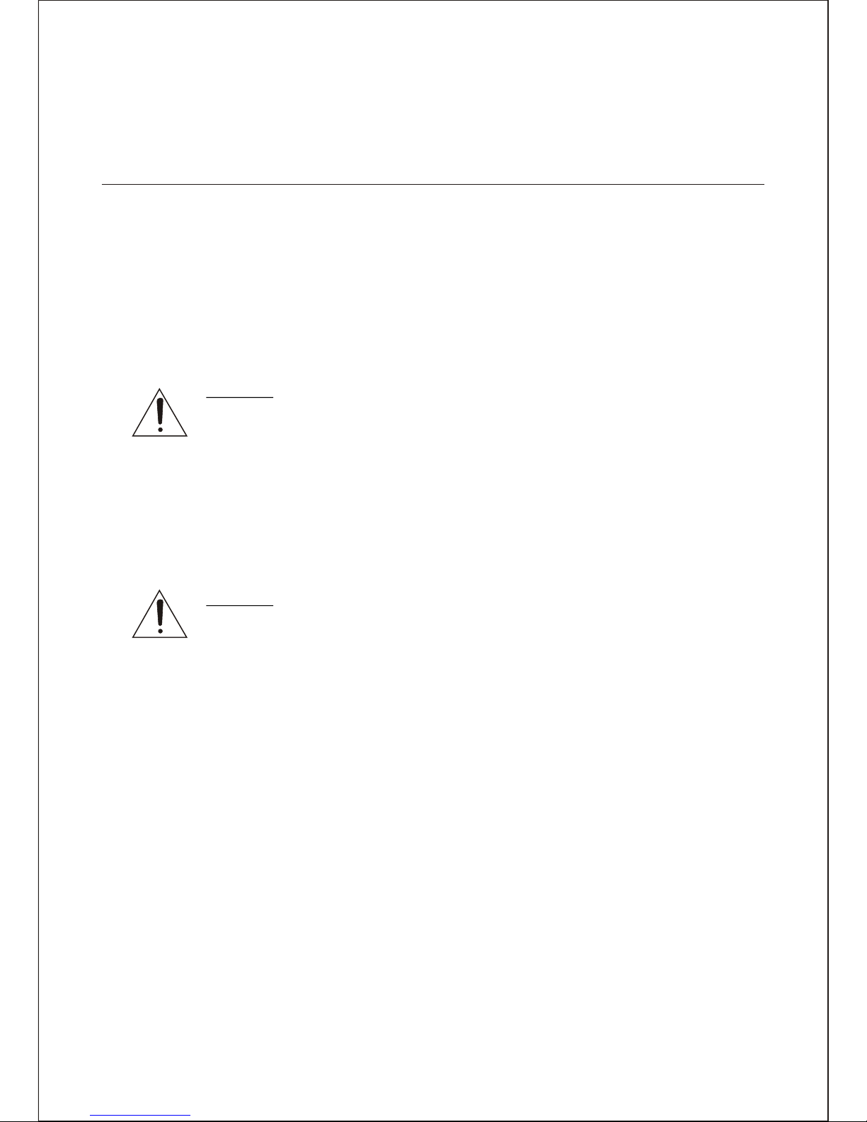
Should any liquid or solid object fall into the cabinet,
unplug the unit and have it checked by the qualified
personnel before operating it any further.
Unplug the unit from the wall oulet if it is not going to
be used for several days or more. To disconnect the
cord, pull it out by the plug. Never pull the cord itself.
Allow adequate air circulation to prevent internal heat
build-up. Do not place the unit on surfaces (rugs,
blankets, etc.) or near materials(curtains, draperies)
that may block the ventilation holes.
Height and vertical linearity controls located at the
rear panel are for special adjustments by qualified
personnel only.
Do not install the unit in an extremely hot or humid
place or in a place subject to excessive dust,
mechanical vibration.
The unit is not designed to be waterproof.
Exposure to rain or water may damage the unit.
Clean the unit with a slightly damp soft cloth.
Use a mild household detergent. Never use strong
solvents such as thinner or benzine as they might
damage the finish of the unit.
Retain the original carton and packing materials for
safe transport of this unit in the future.
Safety ----------------------------------------- Installation -----------------------------------
Cleaning --------------------------------------
PRECAUTIONS
TO REDUCE THE RISK OF FIRE OR ELECTRIC SHOCK, DO NOT EXPOSE THIS PRODUCT
TO RAIN OR MOISTURE. DO NOT INSERT ANY METALLIC OBJECTS THROUGH THE
VENTILATION GRILLS OR OTHER OPENINGS ON THE EQUIPMENT.
WARNING AND CAUTIONS
3
Page 4
FCC COMPLIANCE STATEMENT
INFORMATION TO THE USER: THIS EQUIPMENT HAS BEEN
TESTED AND FOUND TO COMPLY WITH THE LIMITS FOR A "CLASS
A" DIGITAL DEVICE, PURSUANT TO PART 15 OF THE FCC RULES.
THESE LIMITS ARE DESIGNED TO PROVIDE REASONABLE
PROTECTION AGAINST HARMFUL INTERFERENCE WHEN THE
EQUIPMENT IS OPERATED IN A COMMERCIAL ENVIRONMENT.
THIS EQUIPMENT GENERATES, USES, AND CAN RADIATE RADIO
FREQUENCY ENERGY AND IF NOT INSTALLED AND USED IN
ACCORDANCE WITH THE INSTRUCTION MANUAL, MAY CAUSE
HARMFUL INTERFERENCE TO RADIO COMMUNICATIONS.
OPERATION OF THIS EQUIPMENT IN A RESIDENTIAL AREA IS
LIKELY TO CAUSE HARMFUL INTERFERENCE IN WHICH CASE
THE USER WILL BE REQUIRED TO CORRECT THE INTERFERENCE
AT HIS OWN EXPENSE.
CAUTION : CHANGES OR MODIFICATIONS NOT EXPRESSLY
APPROVED BY THE PARTY RESPONSIBLE FOR COMPLIANCE COULD
VOID THE USER'S AUTHORITY TO OPERATE THE EQUIPMENT.
THIS CLASS A DIGITAL APPARATUS COMPLIES WITH CANADIAN
ICES-003.
WARNING
THIS IS A CLASS A PRODUCT. IN A DOMESTIC ENVIRONMENT THIS
PRODUCT MAY CAUSE RADIO INTERFERENCE IN WHICH CASE THE
USER MAY BE REQUIRED TO TAKE ADEQUATE MEASURES.
CE COMPLIANCE STATEMENT
4
Page 5

1.
2.
3.
4.
5.
6.
6A.
7.
8.
9.
10.
11.
12.
13.
14.
15.
16.
17.
18.
19.
20.
READ INSTRUCTIONS -- All the safety and operating
instructions should be read before the appliance is operated.
RETAIN INSTRUCTIONS -- The safety and operating
instructions should be retained for future reference.
CLEANING -- Unplug video monitor or equipment from the
wall outlet before cleaning. Do not use liquid cleaners or
aerosol cleaners. Use a damp cloth for cleaning.
ATTACHMENTS -- Do not use attachments not
recommended by the video monitor or equipment
manufacturer as they may result in the risk of fire, electric
shock or injury to persons.
WATER AND MOISTURE -- Do not use video monitor or
equipment near water -- for example, near a bathtub,
washbowl, kitchen sink, laundry tub, in a wet basement, or
near a swimming pool, or the like.
ACCESSORIES -- Do not place video monitor or equipment
on an unstable cart, stand or table. The video monitor or
equipment may fall, causing serious injury to a child or adult,
and serious damage to the equipment. Wall or shelf
mounting should follow the manufacturer's instructions, and
should use a mounting kit approved by the manufacturer.
Video monitor or equipment and cart
combinations should be moved with
care. Quick stops, excessive force,
and uneven surfaces may cause the
equipment and cart combination to overturn.
VENTILATION -- Slots and openings in the cabinet and the
back or bottom are provided for ventilation, and to ensure
reliable operation of the video monitor or equipment and to
protect it from overheating. These openings must not be
blocked or covered. The openings should never be blocked
by placing the video monitor or equipment on a bed, sofa,
rug, or other similar surface. Video monitor or equipment
should never be placed near or over a radiator or heat
register. Video monitor or equipment receiver should not be
placed in a built-in installation such as a bookcase unless
proper ventilation is provided.
POWER SOURCES -- Video monitor or equipment should
be operated only from the type of power source indicated on
the marking label. If you are not sure of the type of power
supplied to your home, consult your video monitor or
equipment dealer or local power company. For video monitor
or equipment designed to operate from battery power refer to
the operating instructions.
GROUNDING OR POLARIZATION -- This video monitor
may be equipped with a polarized alternating - current line
plug (a plug having one blade wider than the other). This plug
will fit into the power outlet only one way. This is a safety
feature. If you are unable to insert the plug fully into the outlet,
try reversing the plug. If the plug should still fail to fit, contact
your electrician to replace your obsolete outlet. Do not defeat
the safety purpose of the polarized plug.
Alternate Warnings - This video monitor is equipped with a
three-wire grounding-type plug, a plug having a third
(grounding) pin. This plug will only fit into a grounding-type
power outlet. This is a safety feature. If you are unable to
insert the plug into the outlet, contact your electrician to
replace your obsolete outlet. Do not defeat the safety
purpose of the grounding-type plug.
POWER CORDS -- Protect the power cord from being
walked on or pinched particularly at plugs, convenience
receptacles, and the point where they exit from the apparatus.
HEED WARNINGS -- Follow all instructions marked on the
video monitor or equipment.
LIGHTNING -- For added protection for video monitor or
equipment during a lightning storm, or when it is left
unattended and unused for long periods of time, unplug it
from the wall outlet and disconnect the antenna or cable
system. This will prevent damage to the video product due to
lightning and power-line surges.
OVERLOADING --Do not overload wall outlets and
extension cords as this can result in a risk of fire or electric
shock.
OBJECT AND LIQUID ENTRY -- Never push objects of any
kind into video monitor or equipment through openings as
they may touch dangerous voltage points or short-out parts
that could result in a fire or electric shock. Never spill liquid of
any kind on the product.
SERVICING -- Do not attempt to service video monitor or
equipment yourself as opening or removing covers may
expose you to dangerous voltage or other hazards. Refer all
servicing to qualified service personnel.
DAMAGE REQUIRING SERVICE -- Unplug video monitor or
equipment from the wall outlet and refer servicing to qualified
service personnel under the following conditions:
A. When the power-supply cord or the plug has been
damaged.
B. If liquid has spilled, or objects have fallen into the video
product.
C. If the video product has been exposed to rain or water.
D. If the video product does not operate normally by
following the operating instructions, adjust only those
controls that are covered by the operating instructions as an
improper adjustment of other controls may result in damage
and will often require extensive work by a qualified technician
to restore the video product to its normal operation.
E. If the video product has been dropped, or the cabinet
damaged.
F. When the video product exhibits a distinct change in
performance -- this indicates a need for service.
REPLACEMENT PARTS -- When replacement parts are
required, be sure the service technician has used
replacement parts specified by the manufacturer or that have
the same characteristics as the original part. Unauthorized
substitutions may result in fire, electric shock or other
hazards.
SAFETY CHECK -- Upon completion of any service or
repairs to this video product, ask the service technician to
perform safety checks to determine that the video product is
in proper operating condition.
FIELD INSTALLATION -- This installation should be made by
a qualified service person and should conform to all local
codes.
Do not install near any heat sources such as radiators, heat
registers, stoves, or other apparatus (including amplifiers)
that product heat.
IMPORTANT SAFEGUARDS
5
Page 6

TABLE OF CONTENTS
CHAPTER 1. INTRODUCTION 7
1-1. FEATURES 7
CHAPTER 2. INSTALLATION 8
2-1. Monitor Installation with Cameras 8
2-2. Installation with a analog VCR or Security Time-lapse VCR 11
2-3. Installation with secondary monitors 13
2-4. Installation with Alarm Devices 15
2-5. Installation with a Two-way Intercom 17
CHAPTER 3. OPERATION 18
3-1. Front keys and Their Functions 18
3-2. Display Mode 21
3-3. Enter key in the quad display mode 22
3-4. Camera key in the freeze mode 23
3-5. Audio channel selection in the QUAD display 23
3-6. Volume control 23
3-7. Alarm Operation 24
CHAPTER 4. MENU 25
4-1. Navigating the menu 26
4-2. Monitor Picture control menu 26
4-3. System Shutdown 26
4-4. Entering the main menu 27
4-5. TIME/DATE 28
4-6. DISPLAY 29
4-7. CAMERA 29
4-8. Alarms 31
4-9. RECORDING SETUP 35
4-10. Disk Setup 39
4-11. Communications 40
4-12. Unit Setup 43
4-13. Entering the SEARCH menu 45
APPENDIX A. REAR SIDE OF MONITOR 48
APPENDIX B. TROUBLESHOOTING PROCEDURES 50
APPENDIX C. MAINTENANCE 51
EQUIPMENT SPECIFICATIONS 52
6
Page 7

CHAPTER 1.
INTRODUCTION
1-1. FEATURES
The monitor is an observation system with four-channel color multiplexer DVR processor.
The monitor has a motion detection system. Motion detection sensitivity can be adjusted
and the user can set day and night motion detection schedules. The monitor operates as
a duplex recorder of high quality video and one channel audio and supports the network.
The monitor has the following features :
*
*
*
*
*
*
*
*
*
*
*
*
*
*
*
*
*
*
*
15'' Flat Color CRT Monitor.
Compatible with standard color cameras and other standard video sources.
Simple operator menus and easy to use front panel controls.
Automatical switching between NTSC and PAL according to the video format of
camera 1.
Digital Recording and playback using the internal hard disk.
Records up to 60 NTSC (50 PAL) Images per Second.
Full triplex operation allows simultaneous recording, playback, and live viewing.
Full Screen and camera sequencing with programmable sequence dwell times.
On-screen display includes date, time, sequence, freeze, alarm, motion detection,
video loss, audio channel, and 8-character camera titles.
Each camera has two programmable motion-detection areas for day and night setting.
Nonvolatile program memory saves all user settings and protects them against power
outages.
Alarm input polarity is user selectable.
Video Freeze and Electronic X2 Zoom with digital pan and tilt on the full-screen mode.
Four BNC input connectors and four BNC "Loop-Through" Video output connectors.
Recorder modular port - allows you to copy the monitor display, to monitor the
videotape or DVR backup, or to output to the secondary monitor.
Scheduled recording -possible to perform recording automatically at a scheduled
time on a designated day of a week.
Event Recording -At an event occurrence such as when an alarm signal is supplied,
recording mode (quality and recording rate) can be changed to high quality to record
pictures.
Simultaneous live view and playback view -In the playback mode, you watch the
live camera and playback camera in the 3 X 3 display screen simultaneously.
Panorama Playback-In the playback mode, you watch the panorama playback of
each camera.
7
Page 8
CHAPTER 2.
INSTALLATION
2-1. Monitor Installation with Cameras
The observation monitor must be installed by qualified service and installation personnel.
The installation must be in accordance with all local and federal electrical and building
codes.
Perform the following steps to install the observation monitor. See Figure 1.
A. Unpack the observation monitor.
B. Place the observation monitor in a convenient location.
Do not plug the power cord into a power outlet until step J.
Caution:
The MAIN POWER on the rear of the monitor must be turned off
before camera cables are plugged into the camera ports, which are
also on the rear of the monitor. Plugging a camera cable into the
monitor with the power on could damage the monitor and/or camera.
C. Select an appropriate location for the cameras.
D. Install cameras to be connected to the monitor.
E. Route the assembled cable from the monitor to the camera.
Caution:
Be careful when routing the cable from the camera to the monitor.
Try not to put unnecessary strain on the cable or connectors.
The cable can be damaged if pulled by the connectors.
Do not place the cable next to fluorescent lights; interference may
result.
Do not use staples to support the cable, as you may damage the cable.
If the provided camera cable is not long enough, do not substitute a
telephone cable. Using a telephone cable could damage the camera
and/or the monitor.
F. For modular type, plug the cable into the connector port labeled "MONITOR" on the
rear of the camera.
G. For BNC type, plug the cable into the connector port labeled "VIDEO OUT" on the
rear of the camera.
H. Plug the other end of the cable into the corresponding camera connector port on the
rear of the monitor. The ports are labeled "CA1" for camera one, "CA2" for camera
two, etc.
8
Page 9

I. Repeat steps D through G for additional observation cameras.
Caution:
Do not plug an observation camera and a standard security camera into the same
camera port on the rear of the observation monitor; i.e, an observation camera into
the RJ-11-E for CA1 and a BNC cabled standard security camera on the BNC input
for CA1.
NOTE:
Connecting a cable to the output BNC connector disconnects the termination for
that camera input signal, therefore an unused cable should be removed from the
BNC connector.
J. Plug the power cord for the monitor into a power outlet.
K. Turn on the MAIN POWER switch on the rear of the monitor and the POWER switch
on the front of the monitor.
L. The monitor displays a picture.
9
Page 10
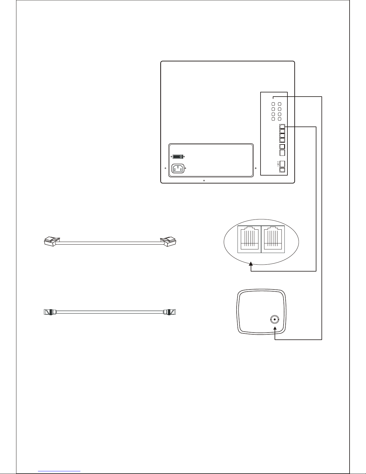
<FIGURE 1> Monitor with Cameras
AC IN
ON
OUTIN
1
2
3
4
CA1
OFF
CA2
CA3
CA4
RECORDER
ALARM
OUT
NO
COM
NC
RS485
NETWORK
Modular Camera Rear View
MONITOR INTERPHONE
BNC Camera Rear View
VIDEO OUT
Modular Cable
connector to Monitor
Modular Cable
connector to Camera
BNC Cable
connector to Monitor
BNC Cable
connector to Camera
Monitor Rear View
10
Page 11

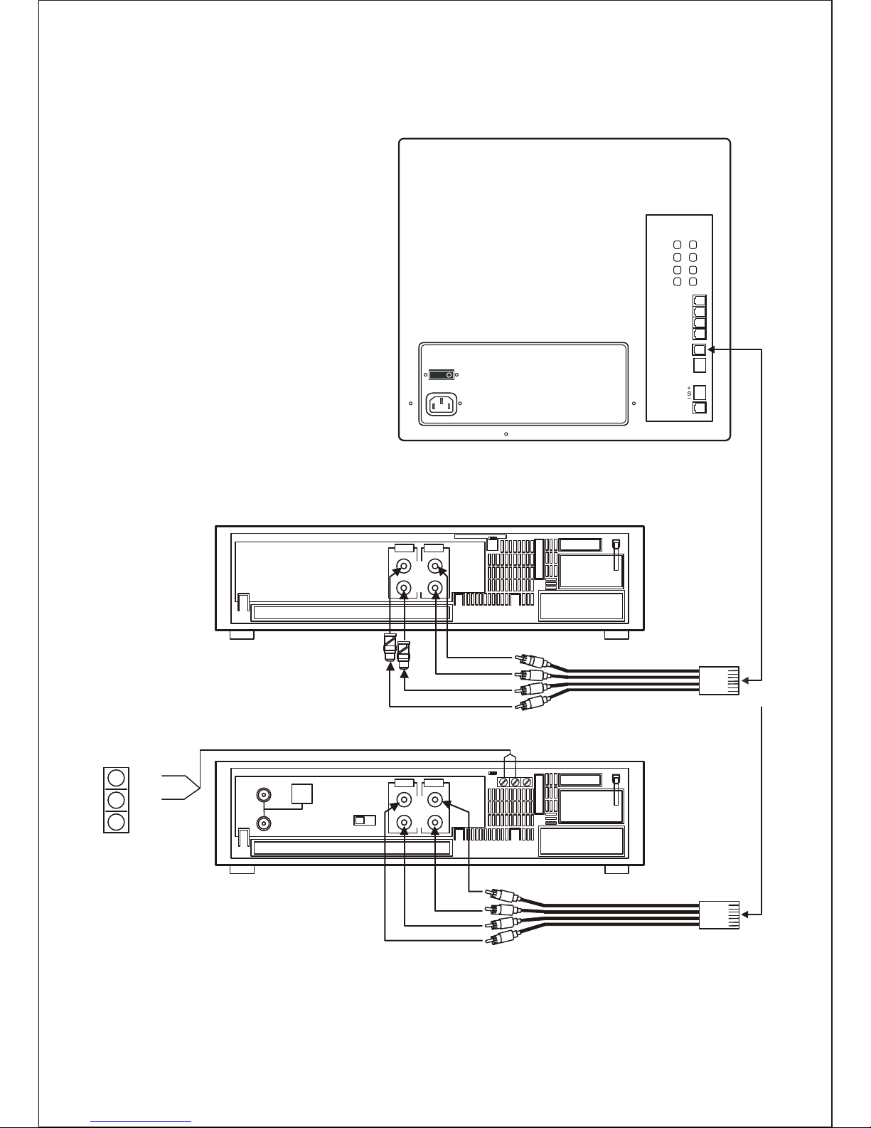
2-2. Installation with a analog VCR or Security Time-lapse VCR
The observation monitor has an internal hard disk for recording and playback.
But sometimes you may want to copy the playback of the internal hard disk using an
analog VCR tape.
At this time, perform the following steps after installing the monitor. See Figure 2.
A. Obtain the following equipment:
a. Analog VCR.
b. VCR interconnection cable.
c. Videotape.
B. Place the VCR in a convenient location.
(usually within reach of the observation monitor)
C. Plug the Modular connector of the VCR interconnection cable into the "RECORDER"
port on the rear of the monitor.
D. Connect the "Audio In" connector to the "Audio In" port on the VCR.
E. Connect the "Audio Out" connector to the "Audio Out" port on the VCR.
F. Connect the "Video In" connector to the "Video In" port on the VCR.
Use a RCA to BNC adapter if necessary.
G. Connect the "Video Out" connector to the "Video Out" port on the VCR.
Use a RCA to BNC adapter if necessary.
H. Press the VCR button on the front of the monitor.
I. Program the VCR using the manufacturer's instructions.
J. Press the mode button on the front of the monitor to return to a normal operation
mode.
K. Start recording using the manufacturer's instructions.
11
Page 12
IN
FROM
ANT
OUT TO TV
OUT
IN
VIDEO AUDIO
OUT
OUT
IN
VIDEO A UDIO
OUT
IN
IN
AC IN
ON
OUTIN
1
2
3
4
CA1
OFF
CA2
CA3
CA4
RECORDER
ALARM
OUT
NO
COM
NC
RS485
NETWORK
Monitor Rear View
Typical Time-Lapse Recorder Rear View
RCA to BNC
Adaptor
VCR Interconnection cable
AUDIO OUT
AUDIO IN
VIDEO IN
VIDEO OUT
Typical Event Recorder Rear View
OR
NO
COM
NC
VHF
UHF
CH3
CH4
VCR Interconnection cable
<FIGURE 2> Observation Monitor with a recorder (Modular Type)
12
Page 13

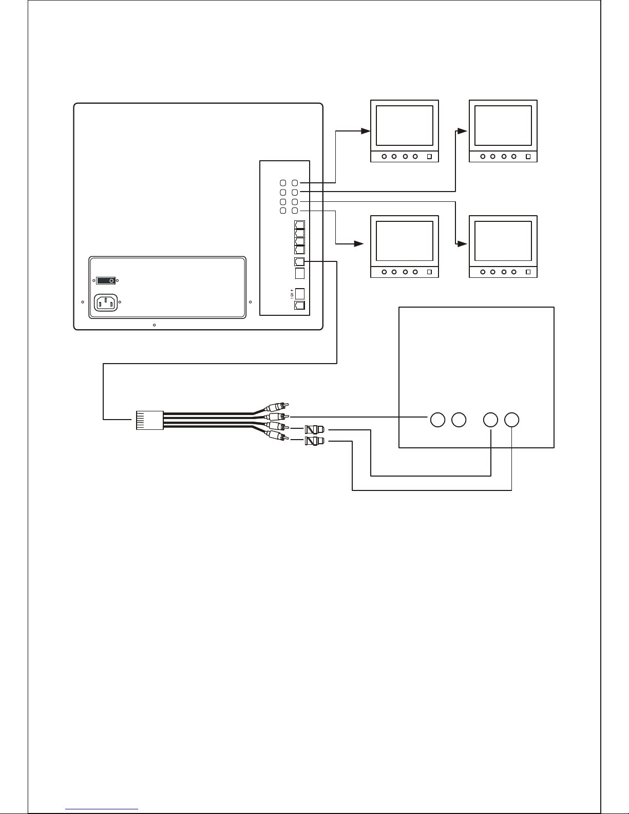
2-3. Installation with secondary monitors
The observation monitor has four video looping-out BNC jacks and one VCR modular
jack.
Perform the following steps after installing the monitor. See Figure 3.
A. Obtain the following equipment:
a. Monitors.
b. VCR interconnection cable.
c. BNC cables.
B. Place the secondary monitor and looping-out monitors in a convenient location.
C. Plug the Modular connector of the VCR interconnection cable into the "RECORDER"
port on the rear of the monitor.
D. Connect the "Audio In" connector to the "Audio In" port on the secondary monitor.
E. Connect the "Video In" connector to the "Video In" port on the
Use a RCA to BNC adapter and BNC cable if necessary.
F. Connect the "Video Out" connector to the "Video Out" port on the
Use a RCA to BNC adapter and BNC cable if necessary.
G. Connect the "Video Out" connector to the "Video Input" port on the looping-out
monitor for camera1.
H. Repeat step G for camera 2, 3, 4.
secondary monitor.
secondary monitor.
13
Page 14
VIDEO OUT
OUTIN
VIDEO
OUTIN
AUDIO
AC IN
ON
OUTIN
1
2
3
4
CA1
OFF
CA2
CA3
CA4
RECORDER
ALARM
OUT
NO
COM
NC
RS485
NETWORK
Monitor Rear View
VCR Interconnection cable
RCA to BNC
Adaptor
OUT
IN
OUT
IN
AUDIO OUT
VIDEO IN
AUDIO IN
<FIGURE 3> Observation Monitor for secondary monitors
14
Page 15

2-4. Installation with Alarm Devices
The monitor can annunciate alarms and activate a recorder or other external alarm device
when an alarm is received at the observation monitor.
Perform the following steps after the installation of the monitor. See Figure 4
A. Obtain one of the alarm device units
B. Locate a suitable location for the alarm device.
C. Mount the alarm device using the manufacturer's instructions.
D. Route the alarm device cable from the alarm device to the observation camera.
E. Connect the ends of the cable to the alarm device following the manufacturer's
instructions.
F. Turn OFF the MAIN POWER switch on the observation monitor.
G. Plug the RJ-11-E connector of the alarm device cable into the interphone port, on the
rear of the camera or plug a dual alarm interface adapter into the interphone port and
plug the alarm device cable(s) into the dual alarm interface adapter.
Caution:
Be careful when routing the cable from the camera to the alarm device. Try not to
put unnecessary strain on the cable or connectors.
The cable can be damaged if pulled by the connectors. Do not place the cable next
to fluorescent lights; interference may result.
Do not use staples to support the cable, as you may damage the cable.
If the provided camera cable is not long enough, do not substitute a telephone
cable. Using a telephone cable could damage the camera and/or alarm device.
Alarm cable may be added to the alarm device cable if it is not long enough.
All connections should be properly connected and insulated to prevent
electrical shock and fire hazards.
H. Turn on the MAIN POWER switch for the observation monitor and the POWER switch
on the front of the monitor.
Place the monitor in the desired operating mode.
15
Page 16
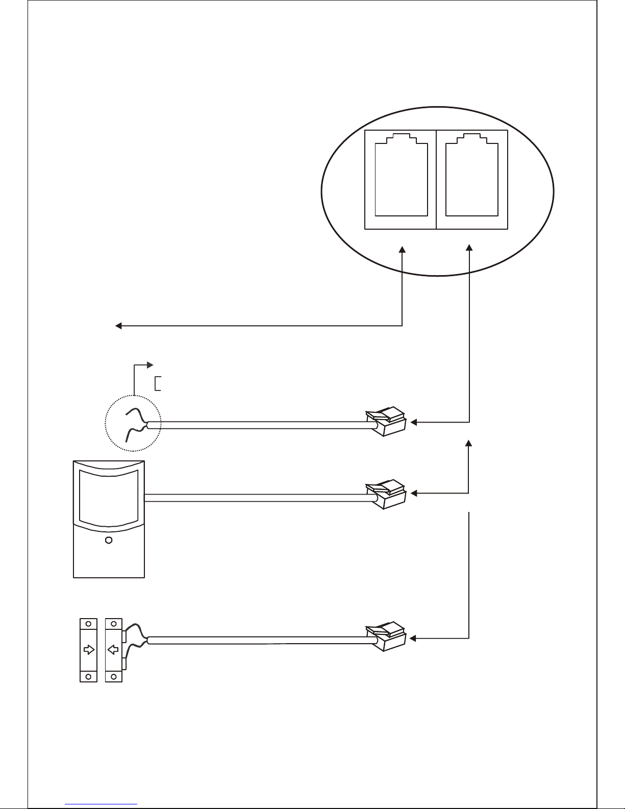
MONITOR INTERPHONE
Camera Rear View
To Monitor
Wire color
Black : Alarm input
Shield : Ground
External Alarm Device Cable
OR
OR
External Alarm Device Cable
Passive Infrared Detector W/Power Supply
<FIGURE 4> Alarm Device Installation (Modular Type)
16
Page 17
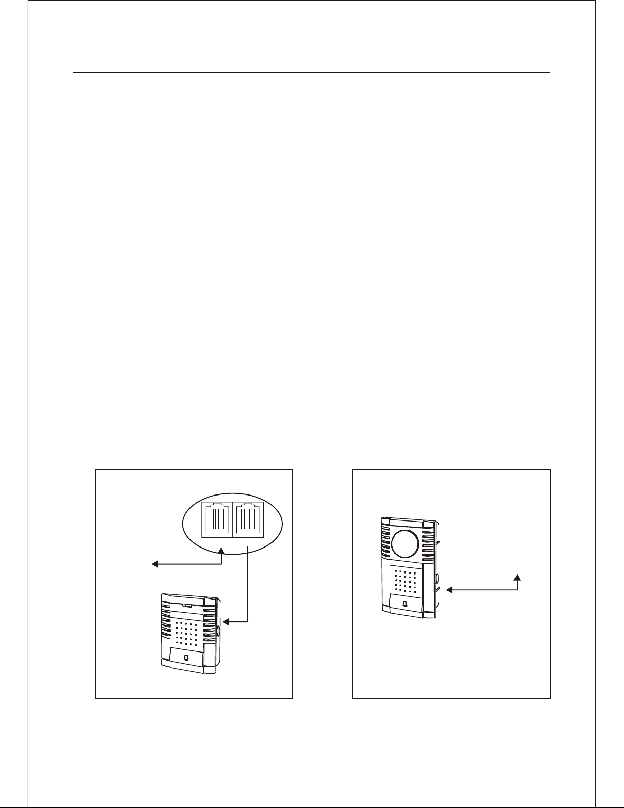
2-5. Installation with a Two-way Intercom
The monitor has the ability to have a two-way intercom between the monitor and the
camera location.
Perform the following steps after installing the monitor. See Figure 5.
A. Obtain an intercom station.
B. Select a suitable location for the intercom station. The typical mounting height should
be between 30'' and 42'' above the floor for easy access.
C. Route the intercom cable from the observation camera to the intercom station.
D. Plug one end of the cable into the jack on the rear of the intercom station.
E. Turn OFF the MAIN POWER switch on the observation monitor.
F. Plug the RJ-11-E connector of the intercom cable into the interphone port, on the rear
of the camera.
Caution:
Be careful when routing the cable from the camera to the intercom station.
Try not to put any unnecessary strain on the cable or connectors.
The cable can be damaged if pulled by the connectors.
Do not place the cable next to fluorescent lights; interference may result. Do not
use staples to support the cable, as you may damage the cable. If the provided
camera cable is not long enough, do not substitute a telephone cable. Using a
telephone cable could damage the camera and/or alarm device.
G. Turn on the MAIN POWER switch for the observation monitor, and the POWER
switch on the front of the monitor.
H. Place the monitor in the desired operating mode.
To Monitor
CAMERA
BACK OF CAMERA
MONITOR INTERPHONE
CAMERA WITH BUILT-IN INTERCOM
VIDEO DOOR
PHONE CAMERA
To Monitor
INTERCOM
<FIGURE 5> Two-way Intercom Installation
17
Page 18

CHAPTER 3.
OPERATION
3-1. Front keys and Their Functions
CA1 CA2 CA3 CA4
TALK QUAD SEQ MODE
AUDIO
VOLUME
MUTE
1 2 3 4 5 6
<FIGURE 6> Front Panel
PART FUNCTION DESCRIPTION
1 SPEAKER Sound from the camera locations, the RECORDER audio, or the
playback audio can be monitored from the internal speaker.
2 TALK Press and hold the TAL K to send audio from the monitor's
built-in microphone to an optional intercom. The LED above the
talk Key is illuminated during the operation.
2 QUAD The QUAD key is used to change the screen to the QUAD
display in the live mode. The LED above the QUAD key is
illuminated during the operation.
In the playback mode, pressing QUAD key will display the
quad screen and pressing QUAD key again will display
the 3x3 screen with four live cameras and four playback
cameras.
2 SEQ Press SEQ key is used to change the screen to the sequence
display in the full-screen display mode. The LED above the SEQ
key is illuminated during the operation.
2 MODE Press MODE to switch the monitor into the RECORDER mode in
the live display mode. In this RECORDER mode, the monitor
displays the video signal through the RECORDER input port.
The LED above the mode key is illuminated during the
RECORDER mode. Press MODE again to switch the monitor
into the live display mode from RECORDER display mode.
Press MODE to return to the live display mode from the playback
mode.
18
Page 19

PART FUNCTION DESCRIPTION
2 1~4 These CAMERA NUMBER keys are used to display a camera in
the full-screen displayed mode. In the playback mode, pressing
camera key again will display the panorama display mode.
The LED above the camera key is illuminated during the
operation.
3 ARROW The Up, Down, Left and Right keys are used whenever you
need to move the screen in the zoom mode and in the menu
mode.
3 ENTER The ENTER key is used to select a submenu or menu items, or
save selections made in menus.
3 MUTE
(LEFT)
Press MUTE key to set the audio level to the minimum level.
AUDIO
(RIGHT)
Press AUDIO key to change the camera audio signal in the
QUAD display mode.
3
Volume
UP/DOWN
Press Volume DOWN key to decrease the volume level.
Press Volume UP key to increase the volume level.
3
4 ZOOM Press ZOOM key to enter or exit the Zoom Mode in the
full-screen mode only.
The LED above the zoom key is illuminated during the operation.
4 RECORD Press RECORD key to record cameras.
Press RECORD key to stop recording again if enabled in the
menu. The LED above the record key is illuminated during the
record mode.
4 PAUSE Press PAUSE key to freeze the screen in the live mode.
Press PAUSE again to unfreeze the screen in the live mode and
the freeze mode.
Press PAUSE key to pause playback picture in the playback
mode. Press PAUSE key again to resume playback in the
pause mode. The LED above the pause key is illuminated
during the pause mode.
4 MENU The MENU key will place the unit in the programmable setup
mode in the live mode. Press MENU key to enter the search
menu in the playback mode.
The LED above the menu key is illuminated during the menu
mode.
19
Page 20

PART FUNCTION DESCRIPTION
4 REWIND Press REWIND key to start rewind playback(x1) of recordings
and press REWIND key again to speed up rewind up to X16 in
the playback mode.
Press REWIND key to speed down rewind for a slow reverse
playback up to X 1/60(50) in the pause mode. The LED above
the rewind key is illuminated during the rewind mode.
4 REVERSE
PLAY
Press REVERSE PLAY key to start reverse playback.
Press REVERSE PLAY key to step back one frame in the pause
mode.
The LED above the reverse playback key is illuminated during
the reverse playback mode.
4 PLAY Press PLAY key to start playback.
Press PLAY key to step forward one frame in the pause mode.
The LED above the playback key is illuminated during the
playback mode.
4 FAST
FORWARD
Press FAST FORWARD key to start playback (x1) of recordings
and press FAST FORWARD key again to speed up the playback
forward up to X16 in the playback mode.
Press FAST FORWARD key to speed down forward for a slow
playback up to X 1/60(50) in the pause mode.
The LED above the fast forward playback key is illuminated
during the fast forward playback mode.
5 POWER Press POWER key to turn the monitor ON. Press POWER key
again to turn the monitor OFF. The power LED illuminates while
the power switch is in the ON position. The main power switch is
located on the back of the monitor.
6 MIC Through this microphone, you can make yourself heard at the
camera site.
Hold down TAL K key while you talk.
20
Page 21

3-2. Display Mode
The monitor has three display modes.
1. Live display mode : displays live cameras.
2. Playback display mode : displays the recorded camera images from the hard disk.
3. Recorder display mode : displays the video signal from the recorder input port.
The recorder output port is identical to the monitor screen in the live display mode and in
the playback mode.
In the recorder display mode, the recorder output port is the same screen as the live
camera display in the live display mode.
3-2-1. Live Display Mode
A. QUAD-screen display:
Press QUAD key to display the quadrant display mode.
B. Full-screen display:
Press camera number key to display the full-screen display mode.
C. Sequence display:
Press sequence key to display the sequence display mode. The sequence dwell time
can be changed in the camera menu. If the dwell time of a camera is OFF, that
camera skips during the sequence.
D. Digital 2x Zoom display in the full-screen display mode:
Press zoom key to enter the zoom display mode in the full-screen display mode only.
Then pop-up position box displays on the screen.
Move the box using arrow keys and press enter key to display the 2x zoom screen.
At this time, you can also move the position of the picture using arrow keys.
Press zoom key again to exit the zoom display mode.
E. Freeze display:
Press pause key to freeze the screen. Press pause key again to unfreeze the screen.
Press play key to enter the playback mode.
A. QUAD-screen display:
Press QUAD key to display the quadrant display mode.
B. 3X3-screen display:
Press QUAD key again in the quad display mode to display the 3X3-screen display
mode. First four cameos display the playback image and second four cameos display
the live camera images.
3-2-2. Playback Display Mode
21
Page 22

C. Full-screen display:
Press camera number key to display the full-screen display mode.
D. Panorama playback display:
Press the same camera number key again to display the panorama playback display
mode. This panorama playback display is useful to watch the sequential images
simultaneously using the slow speed payback.
E. Digital 2x Zoom display in the full-screen display mode:
Press zoom key to enter the zoom display mode in the full-screen display mode only.
Then pop-up position box displays on the screen.
Move the box using arrow keys and press enter key to display the 2x zoom screen.
At this time, you can also move the position of the picture using arrow keys.
Press zoom key again to exit the zoom display mode.
F. Freeze display:
Press pause key to freeze the recorded camera images. Press pause key again to
unfreeze the recorded camera image.
In the recorder display mode, the monitor displays the signal from the recorder input port
and outputs the camera signal to the recorder output port. So all function operates the
same as the live display.
3-2-3. Recorder display Mode
3-3. Enter key in the quad display mode
Pressing the enter key will display the status window. In this time, you can select other
camera using arrow keys. Pressing the enter again will disappear the status window.
1:CAM1
VIEW : ON
DAY MOTION : ON
NIGHT MOTION : ON
ALARM INPUT : N.O
SENSOR : ON
VIDEOLOSS : ON
RECORDING : ON
4:CAM4
VIEW : ON
DAY MOTION : ON
NIGHT MOTION : ON
ALARM INPUT : N.O
SENSOR : ON
VIDEOLOSS : ON
RECORDING : ON
22
Page 23

3-4. Camera key in the freeze mode
Pressing the pause key will freeze all cameras in the live display mode. In this freeze
mode, you can unfreeze the camera by pressing the camera key and freeze again by the
same camera key again.
Pressing the pause key again will unfreeze all camera in the live display mode.
10:10:10 11/30/2004
CAM1 CAM2
CAM3 CAM4
10:10:10
F CAM1
F CAM3
10:10:10 11/30/2004
F CAM1 F CAM2
F CAM3 F CAM4
10:10:10
CAM1
F CAM3
1
3-5. Audio channel selection in the QUAD display
The audio source is automatically changed to the same camera number as the current
displayed camera in the full-screen mode and the sequence mode. When user selects the
recorder mode, the audio source is changed to the recorder audio input automatically.
Press AUDIO key to change the audio channel in the QUAD-screen mode.
11/30/2004
F CAM2
F CAM4
11/30/2004
F CAM2
F CAM4
1
3-6. Volume control
The volume level can be controlled each camera.
Press VOLUME UP and DOWN to change the volume level. Press MUTE key to mute the
audio.
23
Page 24

3-7. Alarm Operation
A. Single alarm:
When an alarm occurs in the live mode, the following actions occur:
1. The LED indicator of the alarmed camera blinks one time per second.
2. The alarm buzzer sounds until the alarm hold time expires, if enabled.
Note: Pressing any button turns off the alarm buzzer if the alarm acknowledge option
is ON in the Alarms menu.
3. The alarm relay is energized if enabled.
4. The screen is switched to the selected display format set in the Alarms menu.
1) When the alarm display is 2X2, the monitor display format is changed to the 2X2
screen format.
2) When the alarm display is FULL, the monitor display format is changed to the
full-screen display format.
3) When the alarm display is UNCHANGED, the monitor display has no change.
5. The alarm message is displayed at the alarmed camera on the screen.
A: sensor alarm, L: video loss alarm, M: motion alarm
6. The recording speed is changed to the event recording speed set in the record type
menu.
7. All actions are continued until the alarm is reset.
B. Multiple alarms:
Multiple alarms are processed in the order they occur. When multiple alarms occur, the
same actions as in a single alarm situation occur, except the following:
When the alarm display is set to FULL, the monitor is switched between alarmed
cameras in numerical order automatically every alarm dwell time.
C. Alarm reset:
When the alarm hold time of an alarmed camera has elapsed, that camera's alarm
actions are terminated.
When the alarm acknowledge is ON in the alarms menu, pressing any key will
terminate all alarm actions when the real alarms release but when the real alarm is
still exist, pressing any key will turn off the only buzzer. If you want to turn off the relay
when the real alarm is still exist, turn off the relay option in the alarms menu.
D. Alarm during the recorder display mode:
All function operates the same as the live display maintaining the recorder display
mode. If you want to watch the alarmed camera, press mode key.
E. Alarm during the Playback display mode:
When an alarm occurs in the Playback display mode, the monitor exits the playback
display mode and operates the same alarm action as the live display mode.
After alarm actions finished, the monitor maintains the live display mode.
If you want to stay in the playback display mode even if an alarm occurs, set the
display format to UNCHANGED in the Alarms menu.
24
Page 25

CHAPTER 4.
MENU
4-1. Navigating the menu
A cursor (highlighted text) can be moved using the arrow keys on the front panel.
Press the enter key to move to the value field. The value can be changed using the up
and down keys.
After changing the value, press the enter key to move to the option field.
This monitor has three types of means.
· Monitor Picture control menu.
· Main menu.
· Search menu.
Pressing the MENU key will display the pop-up menu window.
MENU
COLOR : 20
BRIGHTNESS : 20
CONTRAST : 25
SHARPNESS : 32
TINT : 32
H-POSITION : 00
V-POSITION : 00
DEFAULT >
MAIN MENU >
SEARCH MENU >
SYSTEM SHUTDOWN >
MENU
COLOR : 25
BRIGHTNESS : 20
CONTRAST : 25
SHARPNESS : 25
TINT : 00
H-POSITION : 00
V-POSITION : 00
DEFAULT >
MAIN MENU >
SEARCH MENU >
SYSTEM SHUTDOWN >
MENU
COLOR : 25
BRIGHTNESS : 20
CONTRAST : 25
SHARPNESS : 25
TINT : 00
H-POSITION : 00
V-POSITION : 00
DEFAULT >
MAIN MENU >
SEARCH MENU >
SYSTEM SHUTDOWN >
MENU
COLOR : 25
BRIGHTNESS : 20
CONTRAST : 25
SHARPNESS : 25
TINT : 00
H-POSITION : 00
V-POSITION : 00
DEFAULT >
MAIN MENU >
SEARCH MENU >
SYSTEM SHUTDOWN >
MENU
COLOR : 25
BRIGHTNESS : 20
CONTRAST : 25
SHARPNESS : 25
TINT : 00
H-POSITION : 00
V-POSITION : 00
DEFAULT >
MAIN MENU >
SEARCH MENU >
SYSTEM SHUTDOWN >
MENU
COLOR : 25
BRIGHTNESS : 20
CONTRAST : 25
SHARPNESS : 25
TINT : 00
H-POSITION : 00
V-POSITION : 00
DEFAULT >
MAIN MENU >
SEARCH MENU >
SYSTEM SHUTDOWN >
MENU
COLOR : 25
BRIGHTNESS : 21
CONTRAST : 25
SHARPNESS : 25
TINT : 00
H-POSITION : 00
V-POSITION : 00
DEFAULT >
MAIN MENU >
SEARCH MENU >
SYSTEM SHUTDOWN >
25
Page 26

4-2. Monitor Picture control menu
These values can be adjusted as below.
· Color : Adjusts color.
· Contrast : Adjusts contrast.
· Brightness : Adjusts brightness.
· Sharpness : Adjusts sharpness.
· Tint : Adjusts hue (disable in the PAL system)
· H-POSITION : Adjusts the horizontal position of the picture.
· V-POSITION : Adjusts the vertical position of the picture.
· DEFAULT > : Press enter to return the picture control values above to the default
values.
4-3. System Shutdown
Before the main power off, you should select the system shutdown option for safe
operation.
If you select YES, the massage of "TURN OFF THE POWER" will display. In this time the
unit stops the all operation and is ready to turn off the main power.
SYSTEM WILL STOP.
ARE YOU SURE?
YES NO
26
Page 27

ENTER PASSWORD
When the password is wrong, the monitor exits the menu display and when the password
is correct, the monitor displays the main menu.
MAIN MENU
TIME/DATE
DISPLAY
CAMERA
ALARMS
RECORDING
DISK
COMMUNICATIONS
UNIT SETUP
MAIN MENU
DISPLAY >
DISK OVERVIEW >
KEY LOCK : OFF
CHANGE USER >
<Supervisor Menu> <USER2 Menu>
4-4. Entering the main menu
There are two types of menus, SUPERVISOR and USER2. The supervisor menu can
display all the menus. The USER2 menu will display only the monitor picture control, the
display, the key lock, the disk overview and change user.
The menu displays according to the password only when the password confirmation is ON.
If the password confirmation is OFF, the menu displays all the menus.
Pressing enter key on the main menu, when the menu's password confirmation is ON, the
confirmation screen displays.
27
Page 28

4-5. TIME/DATE
TIME/DATE SETUP
DATE FORMAT: US (MM/DD/YYYY)
DATE : 11/30/2004 TUE
TIME FORMAT : 24H
TIME : 13:35:59
DAY PERIOD : 09:00 TO 17:00
DAYLIGHT SAVING : OFF:
DATE FROM TO
START : 04/05 02:00 03:00
STOP: 08/30 02:00 01:00
· Date Format : There are three date formats to choose from. The month and days
are each two-digit numbers represented by MM and DD. Years are four-digit numbers
represented by YYYY.
The U.S. format is: MM / DD / YYYY.
Europe's format is: DD / MM / YYYY.
Asia's format is: YYYY / MM / DD. (USA MM / DD / YYYY / , EURO DD / MM / YYYY ,
ASIA YYYY / MM / DD)
· Date: Fill in the date.
· Hour Format: There are two hour-display formats to choose from. One is 24-hour
(military) time. The second is AM/PM. (24H, 12H)
· Time: Fill in the actual time.
· Day Period: Fill in a start time and an end time to define the period during which the
day is active. The night is active for the rest of the 24-hour period.
· Daylight Saving: If you are in an area that does not have Daylight Saving (Summer)
Time, set this option to OFF. When you set this selection to ON, you must set the start
and stop dates and times.
· Start: Set the Month and Date that your area begins Daylight Saving time. Unless
there is an unusual situation, you will not need to set From and To times.
· Stop: Set the Month and Date that your area ends Daylight Saving time. Unless there
is there is an unusual situation, you will not need to set From and To times.
28
Page 29

4-6. DISPLAY
DISPLAY
LIVE PLAYBACK
TIME/DATE : ON ON
TITLES : ON ON
STATUS : ON ON
ALARM : ON ON
AUDIO : ON ON
POSITION : BOT BOT
MENU TIME-OUT : 5 MIN
· Time/Date, Camera Title, Status, Alarm, and Audio: The display option allows you
to select whether to display these on the live display and the playback display.
(ON, OFF)
· POSITION: This OSD position option allows you to select "BOT"(BOTTOM) or "TOP".
· MENU TIME-OUT: The menu can last or exit automatically after the minutes you set
the menu time-out. (OFF: displays continuously, 5minute)
4-7. CAMERA
CAMERA
CAMERA SETUP
CAMERA ADJUSTMENT
SEQUENCE DWELL
CAMERA1 : 03 SEC
CAMERA2 : 03 SEC
CAMERA3 : 03 SEC
CAMERA4 : 03 SEC
· SEQUENCE DWELL: Can be set 1 second to 99 seconds and OFF.
The OFF means the camera skips in the sequence.
The camera setup allows you to set up the title of the individual cameras, to define the
camera to hide even if the camera is installed. You can also adjust the camera picture and
set the sequence dwell time.
29
Page 30

CAMERA SETUP
1: CAM1 ON ON
CAM TITLE VIEW REC
2: CAM2 ON ON
3: CAM3 ON ON
4: CAM4 ON ON
4-7-1. Camera Setup
· TITLE : Enter a title for the selected camera. The title can be up to 8 characters long.
· VIEW : The camera view allows you not to view cameras on the monitor.
This option doesn't affect the recording of cameras.
· REC : The record option allow you not to record cameras.
This option has priority over other recording options. (ON, OFF)
If the view option id OFF, that camera displays the black screen with the massage
"DISABLE" in the live mode and the playback mode.
During editing the camera title, pressing zoom key will display the blank character.
4-7-2. Camera Adjustment
CAMERA ADJUSTMENT
CAMERA NO:CAM1 BRIGHTNESS: 00
CONTRAST : 00
COLOR : 00
DEFAULT > TINT : 00
The camera adjustment allows you to adjust brightness, contrast, color, and hue of
cameras.
· CAMERA NO : Select a camera in the menu or press a camera key on the unit.
The selected camera image appears.
· Adjust the value between MIN and MAX of the bright, contrast, color and tint (disable in
the PAL system).
· To set the default value, press the enter key on the default field.
30
Page 31

4-8. Alarms
ALARMS
SENSOR ALARM
VIDEOLOSS ALARM
MOTION ALARM
ALARM ACKNOWLEDGE : ON
· ALARM ACKNOWLEDGE :
ON : Pressing any key will silence the internal buzzer and turn off the relay only when
the real alarms release.
OFF : Pressing any key cannot silence the internal buzzer and cannot turn off the relay.
4-8-1. Sensor Alarm Setup
SENSOR ALARM SETUP
CAM1 INPUT TYPE : N.O
CAM2 INPUT TYPE : N.O
CAM3 INPUT TYPE : N.O
CAM4 INPUT TYPE : N.O
SCREEN : FULL
DWELL : 03 SEC
HOLD TIME : 20 SEC
LATCH : OFF
RELAY : ON
BUZZER : ON
· Sensor input type : Sensor input type defines the way connectors respond to
external input, in terms of whether they are normally open (N.O), normally closed
(N.C), or if they ignore the input (OFF). The default is normally open (N.O).
· SCREEN : Set the screen mode when an alarm occurs.
There are three possible settings: Full, 2X2 and UNCHANGED.
- Full : When a sensor alarm occurs, the screen displays the camera with the alarm in
the full-screen mode. When sensor alarms occur, the screen sequences cameras with
the alarm in the full-screen mode at the interval of the dwell time.
- 2X2 : When a sensor alarm occurs, the screen switches the 2X2 screen mode.
- UNCHANGED : When a sensor alarm occurs, the screen doesn't change and in the
sequence mode, the monitor keeps the sequence.
· DWELL TIME : The dwell time can be set from 1 to 99 seconds. The screen will
automatically sequence in a multi-alarm condition with the full-screen format.
The default is 3 seconds.
31
Page 32

· HOLD TIME : This allows the user to set the alarm actions to last from 5 to 30
minutes. The hold time starts to count after the sensor alarm releases. The default is
20 seconds. (5-9s, 10s, 15s, 20s, 30s, 1M, 2M, 3M, 5M, 10M, 15M, 30M)
· LATCH : When set to On, a "A" displays on the screen when an alarm condition
occurs. It remains on the screen until it is cleared by entering the main menu.
· RELAY : When set to On, the internal relay will activate during an alarm condition.
(ON, OFF)
· BUZZER: When set to On, the internal buzzer will sound during an alarm condition.
(ON, OFF)
4-8-2. Videoloss Alarm Setup
VIDEOLOSS ALARM SETUP
CAM1 ENABLE : ON
CAM2 ENABLE : ON
CAM3 ENABLE : ON
CAM4 ENABLE : ON
SCREEN : FULL
DWELL TIME : 03 SEC
HOLD TIME : 05 SEC
LATCH : OFF
RELAY : ON
BUZZER : ON
· ENABLE : The enable option defines the video loss alarm is active or not.
(ON: active, OFF: inactive)
· SCREEN : Set the screen mode when a video loss alarm occurs.
There are three possible settings: Full, 2X2 and UNCHANGED.
- Full : When a video loss alarm occurs, the screen displays the camera with the
alarm in the full-screen mode. When video loss alarms occur, the screen sequences
cameras with the alarm in the full-screen mode at the interval of the dwell time.
- 2X2 : When a video loss alarm occurs, the screen switches the 2X2 screen mode.
- UNCHANGED : When a video loss alarm occurs, the screen doesn't change and in
the sequence mode, the monitor keeps the sequence.
· DWELL TIME : The dwell time can be set from 1 to 99 seconds. The screen will
automatically sequence in a multi-alarm condition with the full-screen format.
The default is 3 seconds.
· HOLD TIME : This allows the user to set the alarm actions to last from 5 second to 1
minute. The hold time starts to count after the video loss occurs. The default is 5
seconds.
· LATCH : When set to On, a "L" displays on the screen when a video loss alarm
condition occurs. It remains on the screen until it is cleared by entering the main menu.
32
Page 33

· RELAY : When set to On, the internal relay will activate during a video loss alarm
condition. (ON, OFF)
· BUZZER : When set to On, the internal buzzer will sound during a video loss alarm
condition. (ON, OFF)
4-8-3. Motion Alarm Setup
MOTION ALARM SETUP
CAM1 ENABLE : OFF
CAM2 ENABLE : OFF
CAM3 ENABLE : OFF
CAM4 ENABLE : OFF
SCREEN : FULL
DWELL TIME : 03 SEC
HOLD TIME : 05 SEC
LATCH : OFF
RELAY : ON
BUZZER : ON
MOTION AREA SETUP >
· ENABLE : The enable option defines the motion alarm is active or not.
(ON: active, OFF: inactive)
· SCREEN : Set the screen mode when the motion alarm occurs.
There are three possible settings: Full, 2X2 and UNCHANGED.
- Full : When a motion alarm occurs, the screen displays the camera with the alarm in
the full-screen mode. When motion alarms occur, the screen sequences cameras with
the alarm in the full-screen mode at the interval of the dwell time.
- 2X2 : When a motion alarm occurs, the screen switches the 2X2 screen mode.
- UNCHANGED : When a motion alarm occurs, the screen doesn't change and in the
sequence mode, the monitor keeps the sequence..
· DWELL TIME : The dwell time can be set from 1 to 99 seconds. The screen will
automatically sequence in a multi-alarm condition with the full-screen format.
The default is 3 seconds.
· HOLD TIME : This allows the user to set the alarm actions to last from 5 to 5 minutes.
The hold time starts to count after the motion detects. The default is 5 seconds.
(5second to 5minutes)
· LATCH : When set to On, a "M" displays on the screen when a motion alarm condition
occurs. It remains on the screen until it is cleared by entering the main menu.
· RELAY : When set to On, the internal relay will activate during a motion alarm
condition. (ON, OFF)
· BUZZER : When set to On, the internal buzzer will sound during a motion alarm
condition. (ON, OFF)
33
Page 34

4-8-4. Motion Area Setup
MOTION ALARM SETUP
MOTION
DAY
1:ON
2 : OFF
3 : ALL
4 : INVERSE
: SKIP
: END
CAMERA : CAM1 DAY NIGHT
ENABLE : ON ON
SENSITIVITY : 03 03
DELAY : 00SEC 00SEC
AREA : EDIT EDIT
· CAMERA NO. : Select a camera in the menu or press a camera key on the unit.
The selected camera image appears.
· ENABLE : The enable option defines the motion alarm is active or not for each day
and night.
· SENSITIVITY : Set how much luminance change there must be in the target area.
(1 is the lowest sensitivity and 16 is the highest.)
· DELAY : The delay time is used to make adjustments for scenes that have sudden
changes such as lights and shadows created by headlights of nearby traffic.
The delay can be set from 0 to 5 seconds.
· AREA : When you want to edit the motion area, press enter key on the edit field for
each day and night field. For each case, the indication of day and night displays on the
top of the image.
- Arrows keys : move the cursor position with the cell status. If you want to chage the
cell status, press the key below.
- 1 : press camera 1 key to be the target cell on.
- 2 : press camera 2 key to be the target cell off.
- 3 : press camera 3 key to be all target cells on.
- 4 : press camera 4 key to set all target cells to the reverse side.
-: press enter key to move the cursor not to set the target cell on and off.
-: press zoom key to exit the motion cell area.
34
Page 35

4-9. RECORDING SETUP
RECORDING SETUP
RECORD TYPE >
SCHEDULE >
HOLIDAY SETUP >
AUDIO RECORD : OFF
EVENT RECORD ON STOP : OFF
IMAGE RESOLUTION : FULL
RECORDING STOP ENABLE : ON
· AUDIO RECORD : Enable the AUDIO to ON to record an audio signal. This option is
global setting value. In the schedule-recording mode, you can set the audio recording
to be active or not for each schedule interval when this option is ON.
NOTE : Make certain you comply with all local and federal laws and regulations
when recording audio.
· EVENT RECORD ON STOP : When the unit is on the stop mode and the event
occurs, set this option ON to start recording automatically. Set this option OFF to keep
the stop recording mode.
· IMAGE RESOLUTION : Select one of "FULL" (720 x 240(288) and
"HALF" (360 x 240(288)).
· RECORDING STOP ENABLE : When OFF, the recording stop is prohibited.
When ON, the recording stop is available pressing record key again.
4-9-1. Record Type
· ACTION : Select the record action type between KEY and SCHEDULE
- KEY : Records by the front panel key.
- SCHEDULE : Records according to the schedule.
Even if you select the action to SCHEDULE, the record key can operate. Pressing the
record key will record with the setting value on the key line in the stop period of the
schedule.
35
Page 36

· TYPE : Set the recording speed and quality of the normal record and the event record
for the record key access and the recording schedule.
- IPS : Select the recording speed
NTSC : OFF, 0.1,0.2,0.3,0.5,1,2,3,5,10,15,30,60
PAL : OFF, 0.1,0.2,0.3,0.5,1,2,3,5,8,12,25,50
- QUALITY: Select the recording quality. (BEST, HIGH, GOOD, NORM)
"NORM" is the lowest image quality and "BEST" is the highest image quality.
- AUDIO RECORD: Enable the AUDIO to ON to record an audio signal.
Note: The OFF IPS of the EVENT mode means the recording speed doesn't
change from the normal speed and the OFF IPS of the NORMAL mode means
that camera does not record.
Ex.) You want to record on the event condition and not to record on the normal
condition and, set IPS and QLY(record image quality) for the event condition and Set
IPS to OFF for the normal condition. In this time, the unit starts to record at the event
record speed even if the unit is in the stop mode and will return to the stop mode after
the event finished.
NORMAL EVENT
IPS QLY AUDIO IPS QLY AUDIO
OFF GOOD OFF 30 HIGH ON
4-9-2. Schedule
The schedule has three page and total 30 lines. If your assignment is overlapped, the
lower line has the priority.
SCHEDULE PAGE 1/3
DAY START END REC TYPE
ALL 0 0 : 0 0 0 0 : 0 0 SCHEDULE 1
OFF
_ _ _ _:_ _ _ _:_ _
OFF
_ _ _ _:_ _ _ _:_ _
OFF
_ _ _ _:_ _ _ _:_ _
OFF
_ _ _ _:_ _ _ _:_ _
OFF
_ _ _ _:_ _ _ _:_ _
OFF
_ _ _ _:_ _ _ _:_ _
OFF
_ _ _ _:_ _ _ _:_ _
OFF
_ _ _ _:_ _ _ _:_ _
OFF
_ _ _ _:_ _ _ _:_ _
OFF
_ _ _ _:_ _ _ _:_ _
VIEW DELETE INSERT
1. Move the cursor position using the up and down keys.
2. Press ENTER key to edit.
3. Change the value using up and down keys and move the cursor position using the left
and right keys.
4. Press ENTER key to stop the editing.
5. Press ZOOM key to view the schedule of the week.
36
Page 37

· DAY: Select the day. (MON, TUE, WEN, THU, FRI, SAT, SUN, S-S: Saturday-Sunday,
M-F: Monday- Friday, M-S: Monday- Saturday, ALL: Monday- Sunday)
· Enter the start and end time at 30-minute interval.
· REC TYPE: Select the record type in the record type menu.
4-9-3. Schedule View
SCHEDULE VIEW AM
1 1
HR 0 1 2 3 4 5 6 7 8 9 0 1
MON 111111
TUE
WED
THU
FRI
SAT
SUN
< > MENU
111111 111111 111111
111111 111111 111111 111111
111111 111111 111111 111111
111111 111111 111111 111111
111111 111111 111111 111111
111111 111111 111111 111111
111111 111111 111111 111111
SCHEDULE VIEW PM
1 1 1 1 1 1 1 1 2 2 2 2
HR 2 3 4 5 6 7 8 9 0 1 2 3
MON 111111
TUE
WED
THU
FRI
SAT
SUN
< > MENU
111111 111111 111111
111111 111111 111111 111111
111111 111111 111111 111111
111111 111111 111111 111111
111111 111111 111111 111111
111111 111111 111111 111111
111111 111111 111111 111111
· Press < or > key to go to the next time table.
o means the time is not assigned and in this time the monitor doesn't record.
· Press menu key to go to the previous menu.
37
Page 38

4-9-4. Holidays Setup
Up to 60 holiday days can be set that override the calendar list.
The recording plan and the alarm action of holidays operate as Sunday.
Press enter key to enter the date for holidays.
· <PAGE, >PAGE : Press the left or right key to move the page.
· <<Delete : Press rewind key to delete the selected date.
· >>Insert : Press fast forward key to insert the date line.
· Press ZOOM key to clear the selected date.
HOLIDAYS SETUP PAGE 1/3
MM/DD YEAR DAY
_ _ _ _/_ _
PAGE DELETE INSERT
_
_ _ _ _/_ _ _
_ _ _ _/_ _ _
_ _ _ _/_ _ _
_ _ _ _/_ _ _
_ _ _ _/_ _ _
_ _ _ _/_ _ _
_ _ _ _/_ _ _
_ _ _ _/_ _ _
_ _ _ _/_ _ _
MM/DD YEAR DAY
_ _ _ _/_ _ _
_ _ _ _/_ _ _
_ _ _ _/_ _ _
_ _ _ _/_ _ _
_ _ _ _/_ _ _
_ _ _ _/_ _ _
_ _ _ _/_ _ _
_ _ _ _/_ _ _
_ _ _ _/_ _ _
_ _ _ _/_ _ _
PAGE
38
Page 39

4-10. Disk Setup
DISK SETUP
DISK OVERVIEW >
RECORD MODE : OVERWRITE
DISK FULL WARNING : 95%
DISK FULL ALARM REPLAY: ON
DISK ERASE : OFF
· RECORD MODE : The overwrite mode overwrites older recording when the disk is full.
(OVERWRITE, STOP)
· DISKFULL WARNING : Set the percentage of used disk space at which the disk-full
warning message is displayed.
· DISKFULL ALARM RELAY : Select the number of the output relay that is activated
when a disk-full alarm is generated.
· DISK ERASE : This disk erase is used delete the recorded image from the internal
disk. When you set to ON, the monitor displayed the warning message screen.
DISK ERASE
ALL DATA WILL BE DELETED
ARE YOU SURE?
YES NO
DISK ERASE
ENTER PASSWORD
* * * * * * * *
When you select YES, the monitor requests the supervisor's password.
4-10-1. Disk Overview
DISK OVERVIEW
EARLIEST REC :
LASTEST REC :
DISK CAPACITY : 080 GB
USED SPACE : 0.0%
DISK MODEL : ST380011A
TIME LEFT (APPRX.) : -DAY --:-SECTOR / SEC :
BAD SECTOR : 0 / 0
RECYCLE COUNTER : 0
39
Page 40

· DISK CAPACITY : Shows the total space available in Gigabytes.
· USED SPACE (RECORD POSITION) : Shows the total space used by all video
recordings in the stop record mode and shows the record position in the overwrite
record mode.
· DISK MODEL : Shows the model name of the used disk.
· TIME LEFT (APPRX.) : Shows the left time of the disk. The time is approximately
calculated by the current recording status during 3 minutes.
· SECTOR/SEC : Shows the number of the used sector of the disk at one second.
· BAD SECTOR : Displays the status of HDD.
· RECYCLE COUNTER : Shows the overwrite number of the disk.
4-11. Communications
COMMUNICATION SETUP
ETHERNET ENABLE : ON
ETHERNET IP SETUP >
ETHERNET USER SETUP >
ETHERNET OVERVIEW >
RS485 BAUD RATE : 9600
RS485 MODE : SLAVE
RS485 PROTOCOL : OWN
· ETHERNET ENABLE : Set to ON to allow access the network.
· RS485 BAUD RATE : Set on of 38400, 19200, 9600, 4800, 2400.
· RS485 MODE : Set on of MASTER and SLAVE.
MASTER : When the monitor transmits the command from the Ethernet to the RS485
port.
SLAVE : When the monitor is controlled by a controller.
40
Page 41

4-11-1. Ethernet IP Setup
ETHERNET IP SETUP
UNIT NAME : MONITOR 1
IP ADDRESS : 192.168.021.214
SUBNET MASK : 255.255.255.000
GATEWAY : 192.168.021.213
PORT : 5500
RANGE 1 BEGIN : 000.000.000.000
END : 255.255.255.255
RANGE 2 BEGIN : 000.000.000.000
END : 000.000.000.000
MAC ADDRESS : 00-07-D8-2F-FF-FF
· Enter a unit name up to 12-characters long to be used in the network.
(Default name : MONITOR1)
· Fill in the IP, subnet mask and default gateway addresses.
· Port : Enter a port number. (Default 5500)
Note : You should match this port number with the client S/W.
IP RANGE
· Two IP ranges can be entered to allow access.
· Enter the same begin and end address to specify a single IP address.
· Enter different begin and end addresses ro specify an IP address range.
· Use the up and down arrow keys to move to an IP range list. Press the enter key to
edit entries.
Use the left and right arrow keys to move to an IP entry. Use the up and down arrow
keys to change to an IP entry value. Press the enter key to save the IP range.
The MAC address is read only.
41
Page 42

4-11-2. Ethernet User Setup
ETHERNET USER SETUP
SUPERVISOR
NAME : SUPERVISOR
PASSWORD : - - - - - - - -
USER2
NAME : USER2
PASSWORD :
RIGHTS : LIVE
- - - - - - - -
· Enter a name, up to 12-characters long, for each user.
· Enter a 8-digit password using camera number keys. Then the monitor requests the
password.
If you enter the wrong 8-digit password, "PASSWORD IS NOT CHANGED" is
displayed.
· Set Right to Live to restrict viewing rights to live video only. (LIVE, PB, LIVE+PB)
4-11-3. Ethernet Overview
ETHERNET OVERVIEW
CONNECT TIME :
DISCONNECT TIME :
LOGIN ID :
IP ADDRESS :
ETHERNET SPEED : 00000 KB/SEC
The Ethernet overview displays the status of the Ethernet.
42
Page 43

4-12. Unit Setup
UNIT SETUP
KEY LOCK : OFF
PASSWORD SETUP >
FACTORY DEFAULT >
VIDEO FORMAT : NTSC
UNIT ADDRESS : 001
FACTORY SETUP >
· Key Lock : When On, all keys except the menu key on the front panel are inoperative.
Note : When you set the keylock ON, the monitor inquires the password
pressing menu key.
4-12-1. Password Setup
The Password Setup allows the user to assign PIN codes to one supervisor and one user.
Keep a copy of the supervisor password in a safe place. Once you have changed the
supervisor password from the default setting, you will not be able to access protected
areas without it.
A supervisor password is required to access the main menu. After changing the
passwords, keep it in a safe place. The new password will be the only way to access
certain features of the unit once you have changed from the factory default password.
PASSWORD SETUP
SUPER VISOR : - - - - - - - USER2 :
PASSWORD CONFIRMATION
MENU : OFF
PLAYBACK : OFF
SEARCH : OFF
RECORDING STOP : OFF
SYSTEM SHUTDOWN : OFF
- - - - - - - -
· Enter a name, up to 12-characters long, for each user. Enter a password up to 8-digits
long. (Default Password: SUPERVISOR:11111111, USER2:2222222)
· To protect from access of the main menu, set MENU option to ON.
· To protect from playback and search of the internal disk images, set PLAYBACK option
to ON.
· To protect from search of the internal disk images, set SEARCH option to ON.
43
Page 44

· To protect from stop recording of the internal disk images, set RECORDING STOP
option to ON.
· To protect from shutdown of the system, set SYSTEM SHUTDOWN option to ON.
4-12-2. Factory Default
If you select Factory Defaults, all settings in the menu system are reset to their default value.
FACTORY DEFAULT
USER SETTING WILL BE DELETED.
ARE YOU SURE?.
YES NO
4-12-3. Factory Setup
This setup is for after sales service. if you are not a qualified service technician,
press the MENU key.
44
Page 45

4-13. Entering the SEARCH menu
Pressing enter key on the search menu, when the password confirmation is ON, the
confirmation screen displays.
SEARCH
GO TO FIRST
GO TO LAST
SEARCH BY TIME, DATE
SEARCH BY RECORD LIST
SEARCH BY EVENT LIST
· GO TO FIRST : This option lets the user jump to the earliest recorded time.
· GO TO LAST : This option lets the user jump to the last recorded time.
4-13-1. Search By Time, Date
Enter the start date and time and press enter on the search field.
The unit will instantaneously start play at the date and time entered. If the date and time is
not on the disk it will find the closest match.
SEARCH BY TIME, DATE
DATE TIME
YYYY - MM - DD HH : MM
2004 - 09 - 01 11 : 30 SEARCH
EARLIEST REC : 2004 - 09 - 01 11:30
LASTEST REC : 2004 - 09 - 01 12:30
45
Page 46

4-13-2. Search By Record List
The Search by the record lists all of the recording sessions that are logged on the disk.
Enter that start time and press enter on the search filed.
Press enter key on the search result. Then the result displays as below.
RECORD SEARCH INDEX :1 / 00002
START TIME END TIME
11 / 30 / 2004 11:30 11 / 30 / 2004 11:40
11 / 30 / 2004 11:42 11 / 30 / 2004 12:30
VIEW PLAY
SEARCH BY RECORD LIST
DATE TIME
YYYY - MM - DD HH : MM
2004 - 11 - 30 11 : 30 SEARCH
EARLIEST REC : 2004 - 11 - 30 11:30
LASTEST REC : 2004 - 11 - 30 12:30
· Move the cursor position using up and down arrow keys.
· Move the page using left (< ) and right (>) keys.
· Press enter key to play from that time.
· Press zoom key to want to return to the list after watching image from that time.
4-13-3. Search By Event List
The Search by event lists all of the alarmed events that are logged on the disk.
EVENT SEARCH
DATE TIME CAMERA EVENT
YYYY-MM-DD HH:MM 1 2 3 4 A M L
2004 - 11 - 30 11 : 30 Y Y Y Y Y Y Y
EARLIEST REC : 2004 - 11 - 30 11:30
LASTEST REC : 2004 - 11 - 30 12:30
46
Page 47

Enter the start time and end time.
Select the camera. (Y: enable)
Select the event (A:ALARM, M:MOTION, L:VIDEO LOSS)
Press enter key on the search result. Then the result displays as below.
· Move the cursor position using up and down arrow keys.
· Move the page using left (< ) and right (>) keys.
· Press enter key to play from that time.
· Press zoom key to want to return to the list after watching image from that time.
EVENT SEARCH Index:1 / 00002
START TIME EVENT CAMERA
11/ 30 / 2004 11:35 ALARM 1
11/ 30 / 2004 12:20 ALARM 2
VIEW PLAY
MENU PLAY
· Press enter key to exit the search list menu and to return to the play mode.
· Press menu key to want to return to the list.
47
Page 48

APPENDIX A.
REAR SIDE OF MONITOR
A. 1 General
The Observation Monitor has easy to use connectors making installations as user-friendly
as possible.
A. 2 THE OBSERVATION MONITOR CONNECTORS
The following connectors are located on the observation monitor.
According to the model, some port may be not presented.
AC IN
ON
OUTIN
CA1
CA1
OFF
CA2
CA3
CA4
RECORDER
ALARM
OUT
NO
COM
NC
RS485
NETWORK
CA2
CA3
CA4
BA
C
D
E
F
G
H
<FIGURE 1> Observation Monitor Connection Locations
48
Page 49

A. AC IN SOCKET : Connect the AC Power cord (supplied) to this socket and to a wall
outlet.
B. MAIN POWER : Set the switch to turn main power on or off.
C. CAMERA INPUT/OUTPUT BNC CONNECTORS : For camera inputs and video signal
loop- out of cameras to standard monitor.
D. CA1-4 ~ RJ-11 jacks for modular observation cameras.
E. RECORDER : RJ-11 jack for use with a recording device or a secondary monitor.
F. ALARM OUT : This is a dry relay contact output that changes state whenever an alarm
is received on the monitor. The contacts are rated for a maximum of 24 VDC at 1 Amp.
G. RS485 : Three terminal blocks for RS-485 communication.
H. Network : RJ45 jack for network communication.
CAUTION : Connectors (CA1~CA4, RECORDER) are not for connection to telephone
line.
RECORDER CA1~CA4
Top
Bottom
1
Pin 1
Pin 2
Pin 3
Pin 4
Pin 5
Pin 6
Ground
Audio Out
Video Out
Audio In
Video In
Ground
Pin 1
Pin 2
Pin 3
Pin 4
Pin 5
Pin 6
Alarm / In
+15VDC Out
Intercom Audio Out
Video In
Intercom Audio IN
Ground
1
<FIGURE 2> Monitor jacks
49
Page 50

APPENDIX B.
TROUBLESHOOTING PROCEDURES
B. 1 General
If problems occur at the initial installation phase, verity the equipment has been wired
properly and installed in accordance with the procedures in this manual and with other
operating equipment.
The following problem and solutions highlight basic troubleshooting guidelines.
Problem Possible Solution
a. No Video
1. Verity power to all pieces of equipment in the monitor.
2. Verity that the power switches are in the ON position.
3. Verity that the camera lens cap has been removed from the lens of that the iris of
the lens is open.
b. Video, But No Control
1. Power down the monitor for one minute and then turn the power back ON.
50
Page 51

APPENDIX C.
MAINTENANCE
C. 1 General
This section contains the information on preventive maintenance and cleaning procedures
for the unit.
C. 2 PREVENTIVE MAINTENANCE
Preventive maintenance allow detection and correction of minor faults before they become
serious and cause equipment failure.
Every three months, perform the following steps:
1. Inspect all connecting cables for deterioration or other damage.
2. Clean components with a damp clean cloth.
3. Verity that all the mounting hardware is secure.
51
Page 52

Equipment Specifications
Hour Format 24hour
Day Period 09:00 TO 17:00
Daylight Saving OFF
Display of TIME/DATE ON
Display of TITLES ON
Display of STATUS ON
Display of ALARM ON
Display of AUDIO ON
Display of POSITION BOT(BOTTOM)
Menu time out 5 minutes
Camera titles CAM1 ~ CAM4
Camera View ON(Cam1 ~ Cam4)
Record ON(Cam1 ~ Cam4)
Sequence Dwell time 3 seconds. (Off ~ 99 seconds)
Alarm Acknowledge ON
Alarm Input Polarity Normally Open (N.O)
Alarm Screen Format FULL
Alarm Dwell time 3 seconds. (01 ~ 99 seconds)
Alarm hold time 20 seconds (5 ~ 30 minutes)
Alarm Message Latch OFF
Alarm relay ON
Alarm buzzer ON
Video loss Enable ON
Video loss Screen Format 2X2
Video loss dwell time 3 seconds. (01 ~ 99 seconds)
Video loss hold time 5 seconds (5 second ~ 1 minute)
Video loss relay ON
Video loss latch OFF
Video loss relay ON
Video loss buzzer ON
Motion Enable OFF(Cam1 ~ Cam4)
Motion Screen Format FULL
Motion dwell time 3 seconds. (01 ~ 99 seconds)
Motion Hold time 5 seconds (5second ~ 5 minute)
Motion latch OFF
Motion relay ON
Motion buzzer ON
Record Action KEY
Audio Record OFF
Event Record on stop OFF
Format
Display
2x2 Screen Display
Live
Operating defaults
52
Page 53

Image Resolution FULL
Recording Stop Enable ON
Record Mode Overwrite
Ethernet Enable ON
Ethernet Unit Name MONITOR
Ethernet User Name SUPERVISOR
Supervisor Password 11111111
Ethernet User2 Name USER2
USER2 Password 22222222
USER2 Right LIVE
IP Address 192.168.21.214
Subnet Mask 255.255.255.000
Gateway 192.168.21.213
Port 5500
RS-485 Baud Rate 9600 bps
RS-485 Mode SLAVE
RS-485 Protocol OWN
UNIT Address 001
Supervisor Password 11111111
USER2 Password 22222222
Menu password OFF
Playback password OFF
Search password OFF
Recording stop password OFF
System shutdown Password OFF
Key lock OFF
NTSC/PAL 525 lines, 2:1 Interlace / 625 lines, 2:1 Interlace Video format
Camera 1.0Vp-p, 75 Ohms
Recorder input 1.0Vp-p, 75 Ohms
Recorder output 1.0Vp-p, 75 Ohms
Video level
Audio inputs line level
Audio outputs line level
Audio level
Alarm output One NO and NC contact with shared common;
1.0A and 24V dc(resistive only)
Alarm
Gray shades 256 (8bits)
Color 16 million
Sampling 720 x 480 pixels (NTSC), 720 X 576 pixels (PAL)
Display rate Real time refresh rate
Display
53
Page 54

Alarm input 6-pin modular jack
Alarm output Terminal Block
Audio input 6-pin modular jack : audio input from cameras
Audio output 6-pin modular jack : audio output
Recorder in 6-pin modular jack : video input from the recorder
Recorder out 6-pin modular jack : video output from the recorder
Camera in (1~4) 6-pin modular jack and BNC : composite video input from
cameras
Camera output (1~4) BNC (auto terminating) : video looping output
Network RJ45
RS-485 Terminal Block
Connections
AC 100V~240V, 50/60Hz, 1.9APower requirement
110WPower consumption
Picture tube 15-inch flat, 90 deflection angle, 0.7mm stripe, in-line
Dimensions 363.2 (W) x 342.5 (H) x 462 (D) mm
Weight 17.3 Kg (approx.)
Physical
characteristics
O
Ambient temperature 0 ~ 35 C (32 ~ 95 F)
Ambient humidity 10% ~ 90% (non-condensing)
OOO
Operating
environment
54
Page 55

Page 56

50301820A
15-inch 4-CHANNEL COLOR
MULTIPLEXER DVR MONITOR
 Loading...