

Page 1
PRODUCTION RELEASE & REVISION
REV
DESCRIPT'N/BUYER
DWG No
PARTS No.
NOTES
1.MODEL: HCA-G(H)5FDZ1/NOBRAND
2.MATERIAL: 모조지
BIND : STAPLES-2
BY
148(+/-5)mm
DATE
CHK
A INITIAL ------------------ 50302814 A.K.HAN N.C.PARK 11-17-10
12-06-10
105(+/-5)mm
3.COLOR: TEXT- BLACK
4.SIZE: 105(+/-5)mm x 148(+/-5)mm
5.LABEL: 50201270(81mm x 24mm)
6.ANY CHANGE OR ALTERNATION MUST BE
APPROVED BY HITRON DESIGN TEAM.
LABEL MANUAL NAME (50201270)
김종민
선임
TITLE
SIZE REV.
SCALE
MATERIAL
UNLESS OTHERWISE SPECIFIED
ALL DIMENSIONS ARE IN MM.
- TOLERANCE
LABEL +/- 3
MANUAL +/- 5
GUIDE +/- 5
COLOR
DATE
DRAWN
CHKED
APPROVALS
PARTS LIST
DESCRIPTION/MATERIAL
ITEM QTY
A4
DO NOT SCALE
2
A
MANUAL INSTRUCTION
50302814
A.K.HAN
N.C.PARK
12-06-10
12-06-10
3
INSTRUCTION MANUAL
COLOR CCD
WEATHERPROOF
AF ZOOM CAMERA
ALL-IN-ONE CAMERA
B 7p,15p,16p 변경수정 50302814 A.K.HAN N.C.PARK 12-06-10------------------
재고스티커처리 즉시 적용
Page 2
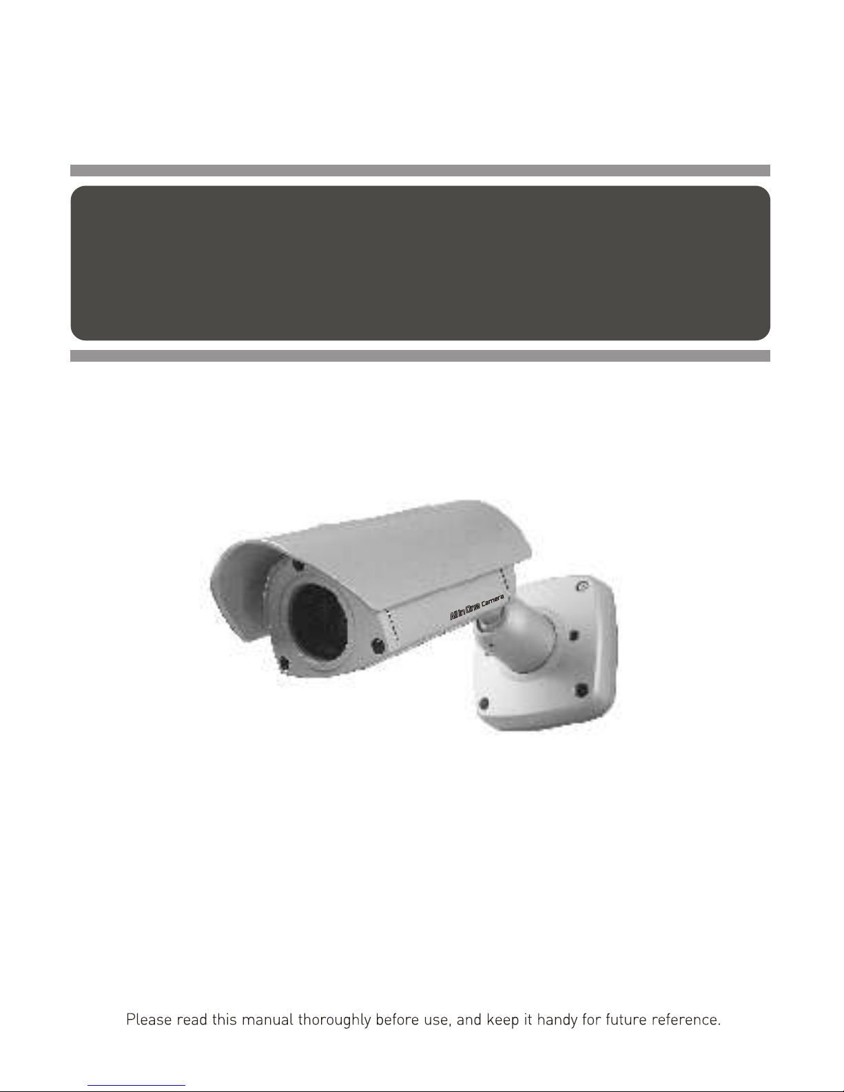
INSTRUCTION MANUAL
COLOR CCD
WEATHERPROOF
AF ZOOM CAMERA
ALL-IN-ONE CAMERA
Page 3

LIMITATION OF LIABILITY
THE INFORMATION IN THIS PUBLICATION IS BELIEVED TO BE ACCURATE IN ALL
RESPECTS, HOWEVER, WE CANNOT ASSUME RESPONSIBILITY FOR ANY
CONSEQUENCES RESULTING FROM THE USE THEREOF. THE INFORMATION
CONTAINED HEREIN IS SUBJECT TO CHANGE WITHOUT NOTICE. REVISIONS OR
NEW EDITIONS TO THIS PUBLICATION MAY BE ISSUED TO INCORPORATE SUCH
CHANGES.
II
Page 4
III
Page 5
IV
Page 6

1. Read these instructions.
2. Keep these instructions.
3. Heed all warnings.
4. Follow all instructions.
5. Do not use this apparatus near water.
6. Clean only with dry cloth.
7. Do not block any ventilation openings. Install in accordance with the
manufacturer's instructions.
8. Do not install near any heat sources such as radiators, heat registers,
stoves, or other apparatus (including amplifiers) that produce heat.
9. Do not defeat the safety purpose of the polarized or grounding-type
plug. A polarized plug has two blades with one wider than the other.
A grounding type plug has two blades and a third grounding prong.
The wide blade or the third prong are provided for your safety. If the
provided plug does not fit into your outlet, consult an electrician for
replacement of the obsolete outlet.
10. Protect the power cord from being walked on or pinched particularly
at plugs, convenience receptacles, and the point where they exit
from the apparatus.
11. Only use attachments/accessories specified by the manufacturer.
12. Use only with the cart, stand, tripod, bracket, or table specified by
the manufacturer, or sold with the apparatus. When a cart is used,
use caution when moving the cart/apparatus combination to avoid
injury from tip-over.
13. Unplug this apparatus during lightning storms or when unused for
long periods of time.
14. Refer all servicing to qualified service personnel. Servicing is
required when the apparatus has been damaged in any way, such
as power-supply cord or plug is damaged, liquid has been moisture,
does not operate normally, or has been dropped.
15. CAUTION THESE SERVICING INSTRUCTIONS ARE FOR USE
BY QUALIFIED SERVICE PERSONNEL ONLY. TO REDUCE THE
RISK OF ELECTRIC SHOCK DO NOT PERFORM ANY SERVICING
OTHER THAN THAT CONTAINED IN THE OPERATING
INSTRUCTIONS UNLESS YOU QRE QUALIFIED TO DO SO.
16. Use Certified/Listed Class 2 power source only.
IMPORTANT SAFEGUARDS
V
Page 7

TABLE OF CONTENTS
1. INTRODUCTION 1
1.1 THE CAMERA FEATURES 1
2. SYSTEM INSTALLATION 2
2.1 PACKAGE CONTENTS 2
2.2 OPERATION REQUIREMENTS 2
3. PART NAME 3
3.1 PART NAME 3
3.2 INSTALLATIONS 3
4. CONNECTION 7
4.1 COLOR LEAD WIRE & COLOR DISPLAY LABEL 7
4.2 EXTERNAL DAY/NIGHT CONTROL & ZOOM PRESET CONTOL 8
4.3 MOTION DETECTION & FACE DETECTION CONTOL 8
4.4 RS-485 CONNECTION 8
4.5 EXTERNAL LENS CONTROL 8
4.6 EXTERNAL A/D KEY CONTROL 9
5. CAMERA ADJUSTMENT 10
5.1 OSD MAIN SCREEN 10
5.2 MAIN MENU 10
6. TROUBLESHOOTING AND MAINTENANCE 14
6.1 TROUBLESHOOTING 14
6.2 MAINTENANCE 15
7. DIMENSIONS 15
8. SPECIFICATIONS 16
VI
Page 8
The 22x AutoFocus Zoom WDR Day & Night Camera provides especially for closed circuit
television (CCTV) and security surveillance application.
IMPORTANT : The user of this camera is responsible for checking and
complying with local, state, and federal laws and statutes concerning the
recording and monitoring of audio signals.
Use at the 12VDC Adapter must provide the power consumption of above 500mA.
Function : - D/N (Day / Night) - DSS (Digital Slow Shutter)
- M/D (Motion Detection) - WDR (Wide Dynamic Range)
- AWB (Auto White Balance) - AE (Auto Exposure)
- AGC (Auto Gain Control) - BLC (Back Light Compensation)
- OSD (On Screen Display) - ZOOM PRESET & TOUR
- NEGA/POSI (Negative / Positive) - P/M(Privacy Mask)
- ALARM(Alarm out) - FREEZE (Rear & still picture)
- E Function (H / V Flip, Rotation) - F/D (Face Detection)
Introduction
1
1.1 THE CAMERA FEATURES
High performance SONY 1/4" EXview HAD CCD
352x zooming capability (Optical : 22x / Digital : 16x)
Ultra Sensitivity Minimum illumination of 0.001 lux @F1.6 (slow shutter)
Support camera control available
ALL-IN-ONE : Auto-focus camera / LENS / Weatheproof housing
Flexible camera angle setting
Concealed cabling
CAUTION :
Excellent picture quality
Various picture effects
Flexible configuration
Use Certified/Listed Class 2 power source only.
RS-485
1
Page 9

2.2 OPERATION REQUIREMENTS
< Typical System Configuration >
2
J-BOX
CAMERA.1
MULTIPLEXER
MONITOR
CONTROLLER DVR / VCR
RS-485
RS-485
RS-485
VIDEO
CAMERA.2 CAMERA.3 ......
VIDEO
System Installation
2
Installation of the camera must be performed by qualified service personnel in accordance
with all local national electrical and mechanical codes must perform installation of the camera.
Perform the following steps to install the camera.
Camera - 1EA
Instruction Manual - 1EA
A/D Remote Controller (option)
The componets for mounting the camera
2.1 PACKAGE CONTENTS
Page 10

3.2 INSTALLATIONS
1. Cable through the wall
with mount base.
2. Using the conduit knockout
punched with the
mount base.
3. Cable through the
junction box with
the mount base.
CAMERA CONTENTS
SUNSHADE
AF CAMERA MODULE
MOUNT BASE
BIMETAL
HEATER
CONNECTION CABLE
CABLE LABEL
POLY BAG
ACCESSORY KIT
MOUNT TORX SCREWS(M6x35.0)(4X)
PLASTIC ANCHORS(4X)
TORX WRENCH(T-20)(1X)
"L" TYPE HEX WRENCH(1X)
3.1 PARTS NAME
Carefully remove the contents from the box, and verity that nothing was damaged
in shipment.
There are three ways of installing the camera.
3
Parts Name
3
Page 11

3.2.1 INSTALLATION 1 (Cable through the wall with the mount base)
A. Drill the mounting location, using the bottom of the mount base as a template.
B. Insert the plastic anchors into the hole which has just drilled.
C. Connect BNC cable and communication lines.
D. Fit the screw holes of the mount base into the plastic anchors.
E. Screw up the M6 torx screws(T-20).
F. Adjust the camera suitably using the pan & tilt function, and fix the camera
using the socket set screw, hexagon wrench.
* Seal around the stand base tightly using the silicon rubber.
Torx Screws (T-20)
M6.0 x 35.0 (4x)
Set Screw
M5.0, L=5.0mm
Plastic Anchors (4x)
Wall
Mount Base
Socket Set Screw
M5.0, L=5.0mm
Hexagon Wrench
4
Page 12

3.2.2 INSTALLATION 2 (Using the conduit knockout punched with Mount Base)
A. Drill the mounting location, using the bottom of the mount base as a template.
B. Insert the plastic anchors into the hole which has just drilled.
C. Connect BNC cable and communication lines.
D. Fit the screw holes of the mount base into the plastic anchors.
E. Remove the conduit knockout punched for the cable entry.
F. Screw up the M6 torx screws(T-20).
G. Adjust the camera suitably using the pan & tilt function, and fix the camera
using the socket set screw, hexagon wrench.
Torx Screws (T-20)
M6.0 x 35.0 (4x)
Socket Set Screw
M5.0, L=5.0mm
Plastic
Anchors (4x)
Wall
Mount Base
Hexagon Wrench
Cable
A conduit knockout punched
for the cable entry
5
Page 13

3.2.3 INSTALLATION 3 (Cable through junction box with mount base)
The camera can be mounted on the junction box using the UNC # 8-32 machine
screws.
Junction Box
Socket Set Screw
M5.0, L=5.0mm
Torx Screws (T-20)
UNC 8-32 x 0.75" (4x)
(not provided)
Hexagon Wrench
6
Page 14

COLOR
RED
WHITE
PINK
SKY-BLUE
BLACK
GRAY
BLUE
GREEN
ORANGE
VIOLET
DESCRIPTION
DC12V(+) / AC24V
DC12V(-) / AC24V
232 TXD
232 RXD
GND
EXT-IN
EXT-OUT
485(-)
485(+)
ADKEY
MD-OUT
BLACK/WHITE
(BLACK)
(VIOLET)
7
CAUTION : Do not connect the power cable until all other connections have been
completed. If you complete the whole connection of cameras, then you have
to cut the extra cable.
TOP
Connection
4
MONITOR
VIDEO(BNC)
RS-485 CONNECTION
Day & Night CONTROL
A/D KEY CONTROL
DVR / VCR
(BLUE)
(GREEN)
(ORANGE)
(BLACK)
(BLACK/WHITE)
(GRAY)
MENU
TELE
NEAR
FAR
WIDE
4.1 COLOR LEAD WIRE & COLOR DISPLAY LABEL
M/D CONTROL
Page 15

8
Connecting to the RS-485 : The Camera can be controlled remotely by an external device
or control system, such as a control keyboard, using RS-485 half-duplex. Connect Market
Rx+, Rx- to Tx+ and Tx- of the RS-485 control system.
Is connect to an external sensor to receive day/night detection signals.
DAY/NIGHT
DAY : OPEN
NIGHT : CLOSED
EXT-IN
(GRAY)
GND
(BLACK)
EXT-IN
*Note: To validate the sensor inputs, select Function menu B/W mode the EXT
COLOR mode: 0V Output
B/W mode: 5V Output
EXT-OUT
EXT-OUT
(BLACK/WHITE)
RS-485
RS-485(-)
(BLUE)
RS-485(+)
(GREEN)
4.2 EXTERNAL DAY/NIGHT CONTROL & ZOOM PRESET CONTROL
External sensor switch ON/OFF
4.4 RS-485 CONNECTION
4.5 POWER CONNECTION
M/D or F/D
4.3 MOTION DETECTION & FACE DETECTION CONTROL
GND
(BLACK)
M/D or F/D-OUT
(VIOLET)
NORMAL mode : 0V Output
ALARM mode : 3V Output
ZOOM PRESET
EXT ZOOM PRESET
NORMAL mode 0V Output
ALARM mode : 3V Output
M/D+EXT or F/D+EXT
POWER
Red
(AC 24V / DC12V)
White
(AC 24V / DC12V)
CAUTION : Use Certified/Listed Class 2 power supply transformer only.
Page 16

9
4.6 EXTERNAL A/D KEY CONTROL
External Controller Circuit Schematic
A/D KEY Control Circuit
Remote Controller
1
1
2
2
1
1
2
2
1
1
2
2
1
1
2
2
1
1
2
2
R22
150
R20
12K
R21
5.6K
Sw10
TELE
R19
22K
Sw11
WIDE
Sw13
FAR
Sw12
NEAR
R18
33K
Sw9
MENU
A/D KEY
A/D KEY
(ORANGE)
Remote Controller
3
MENU
TELE
NEAR
FAR
WIDE
GND
(BLACK)
A/D KEY
(WHITE)
1m95mm
42mm
GND(RED)
Page 17

AF 22X
CAM 001
001X
MF
Camera Adjustment
5
5.1 OSD MAIN SCREEN
10
<MAIN MENU>
FOCUS
WB
AE
BLC/WDR
ALARM/MD/FD
PRIVACY
SPECIAL
EFFECT
CAM SET
END <EXIT>
1
2
3
4
5
6
7
8
5.2 MAIN MENU
<FOCUS MENU>
MODE
DISTANCE
D-ZOOM
D-ZOOM END
ZOOM PRESET
SET PRESET
TOUR CONFIG
END
5.2.1 FOCUS
MODE Select auto, manual, pushauto mode.
DISTANCE Select minimum distance in focus between camera and object.
(0.1/1.0/1.5/2.5/6m)
D-ZOOM Digital Zoom on/off.
D-ZOOM END Select maximum Digital Zoom magnification.
(x2, x3, x4, x6, x8, x12, x16)
ZOOM PRESET Select zoom preset number, Default is x1.(1~10)
SET PRESET Set the zoom position of zoom preset.
TOUR CONFIG Select zoom tour mode.(10 zoom preset to 1 tour mode)
NOTE 1 : When "ZOOM PRESET" is selected, you can adjust the preset zoom location
using the "tele" and "wide" buttons.
NOTE 2 : When after the zoom location has been selected press the "menu" button to
store the location.
1
2
3 4
Camera title
Status of the focus mode
Status of the zoom position
Camera ID
1
2
3
4
Page 18

<WB MENU>
MODE
R GAIN
B GAIN
FEAME ADJ
END
5.2.2 WB (White Balance)
11
<AE MENU>
MODE
SHUTTER
GAIN
DSS
MAX DSS
FLICKERLESS
BRIGHTNESS
END
5.2.3 AE (Auto Exposure)
MODE Select white balance mode.
(AWB/WAWB/INDOOR/OUTDOOR/MANUAL/CRS)
AWB Auto white balance mode.(2500~9500'K)
WAWB Wide range auto white balance mode.(1800~10500'K)
INDOOR Indoor white balance mode.
OUTDOOR Outdoor white balance mode.
MANUAL Manual mode. You can change R and B Gain manually.
CRS Color rolling mode.
R GAIN Adjust R gain value.(0~255)
B GAIN Adjust B gain value.(0~255)
FRAME ADJ Since the color rolling path differs depending on the fluorescent
lamp used, adjust the color rolling frame for each fluorescent lamp.
So press Menu key to adjust frame and after about 10 seconds, the
adjust mode will be finished automatically and 'ENT' turns to 'END'.
suppression
MODE Select Exposure mode.(AUTO1/AUTO2/SHUT PRI/MANUAL)
AUTO1 Auto exposure mode 1.(Use to normal surroundings : indoor)
AUTO2 Auto exposure mode 2.(Use to high brightness surroundings : outdoor)
SHUT PRI Shutter priority exposure mode.
MANUAL Manual exposure mode.
SHUTTER Select shutter speed.(1/60(50)~1/100K)
Can be changed while in SHUT PRI and Manual mode.
DSS Digital slow shutter on/off
MAX DSS Select maximum slow shutter value.(x2~x128)
FLICKERLESS Flickerless on/off
BRIGHTNESS Adjust brightness level.(0~70)
GAIN Gain control.(0~30DB)
<BLC/WDR MENU>
BLC MODE
AREA
LEVEL
WDR MODE
LEVEL
END
5.2.4 BLC/WDR
Page 19

12
5.2.5 ALARM/MD/FD
<ALARM/MD/FD MENU>
MODE
AREA SEL
- - DEFAULT
ADJ TOP/LEFT
ADJ BOT/RIGHT
SENSITIVITY
DWELL TIME
PRESET SEL
END
MODE Select alarm and MD/FD mode.
(OFF/MD/EXT/FD/MD+EXT/FD+EXT)
AREA SEL Select MD area number. (1~4)
Select MD/FD enable/disable.
DEFAULT Set MD area as default.
ADJ TOP/LEFT Adjust the location of the MD area with boundary top and left.
ADJ BOT/RIGHT Adjust the location of the MD area with boundary bottom and right.
SENSITIVITY Adjust sensitivity of MD/FD area. (MD:1~10 / FD:1~64)
DWELL TIME Dwell time setup of zoom preset. (10,20,...,180sec)
PRESET SEL Select zoom preset number.(0FF,1~10)
(When the MD and/or Alarm is/are occurred.)
NOTE1 : The result of face detection can be inaccuracy
BLC MODE Select backlight compensation mode.
(OFF/AUTO/MANUAL)
AREA Select BLC area position.(1~9)
LEVEL Select BLC level.(HIGH/MID/LOW)
WDR MODE Wide dynamic range on/off.
LEVEL Adjust WDR level.(1~100)
5.2.6 PRIVACY
<PRIVACY MENU>
MASK SEL
- - DEFAULT
ADJ TOP/LEFT
ADJ BOT/RIGHT
COLOR
MOSAIC
MOSAIC TYPE
END
MASK SEL Select mask area number.(1~16)
Select mask enable/disable.
DEFAULT Set mask area as default.
ADJ TOP/LEFT Adjust the location of the mask area with boundary top and left.
ADJ BOT/RIGHT Adjust the location of the mask area with boundary bottom and right.
COLOR Select mask color.(1~8)
MOSAIC Mosaic display on/off.
MOSAIC TYPE Mosaic roughness setting. (1 ~ 4)
NOTE1 : The mosaic when the color is transparent, is possible
Page 20

13
<SPECIAL MENU>
SYNC
PHASE
D/N MODE
D/N DELAY
HI-RES
2DNR
3DNR
WHITE DET
LEVEL
END
5.2.7 SPECIAL
<EFFECT MENU>
SHARPNESS
NEGATIVE
D-FLIP
FREEZE
END
5.2.8 EFFECT
SHARPNESS Adjust sharpness of outline.(0~15)
NEGATIVE Select the negative or positive mode.
D-FLIP Select rotate or flip mode.(OFF/H FLIP/V FLIP/ROTATE)
FREEZE Select the real or still mode.
SYNC Select internal or line lock mode.(DC power is internal sync only)
PHASE Adjust sync phase in line lock mode.
D/N MODE Select D/N, Color, BW, EXT mode.
D/N DELAY Adjust the working time of the filter when D/N operated.(5,10,20 sec)
HI-RES Select high resolution mode. (OFF/LOW/MID/HIGH)
2DNR Select 2D noise reduction level.(OFF/01~07)
3DNR Select 3D noise reduction level.(OFF/01~31)
WHITE DET Press the Menu key to execute the White Pixel Detection function
and then the Iris will be closed automatically. When detection is
completed, the operation automatically returns to the normal state.
LEVEL Adjust the threshold level from 1 to 15.(Default is 4)
<CAM SET MENU>
CAM ID
BAUD RATE
PROTOCOL
DISP MODE
DISP ITEM
TITLE
ALARM TEXT
SAVE
END
5.2.9 CAM SET
Page 21

Troubleshooting and Maintenance
6
6.1 TROUBLESHOOTING
If problems occur, verify the installation of the camera with the instruction in this
manual and with other operating equipment.
Isolate the problem to the specific piece of equipment in the system and refer to
the equipment manual for further information.
14
NOTE 1 : You can choose BPS menu appropriate for keyboard protocol.
NOTE 2 : Although you change BAUD RATE or PROTOCOL menu,
the terms of change is not applied unless you select SAVE menu.
NOTE 3 : Does not do power source down while saving
PROBLEM
POSSIBLE SOLUTION
Nothing appears on the screen Are the power cord and line connection between the
camera and monitor made properly?
The image on the screen is dim.
Is the lens dirty?
If so, clean the lens with a soft, clean cloth.
CAM ID Select the camera ID.(1~255)
BAUD RATE Select serial communication speed. (2400/4800/9600/19200bps)
PROTOCOL Select operating protocol.
(FASTRAX/PELCO-P/PELCO-D/COMMAND)
DISP MODE Select display mode.(ON/OFF/PUSH ON)
DISP ITEM Select display item.(1~2)
1 Camera Title and ID display.
2 Camera Title and ID, Zoom lens position display.
TITLE Select camera title menu.(A~Z, 0~9)
ALARM TEXT If the alarm is occurred, the ALARM TEXT established at this menu
will be displayed.
SAVE Save preset parameters of CAM SET MENU.
PROBLEM
POSSIBLE SOLUTION
The camera is not working
properly and the surface of the
camera case is hot.
The contrast on the screen is
too weak.
Is the camera connected to the proper power?
Adjust the contrast feature of the monitor.
Is the camera exposed to strong light?
If so, change the camera position.
ABCDEFGHIJ
KLMNOPQRST
UVWXYA 0123
456789 ( ) :
; . - →← ! < > , '
←→ < > S E
Page 22

6.2 MAINTENANCE
Preventive maintenance allows detection and correction of minor faults before they become
serious and cause equipment failure.
Every three-month, perform the following maintenance.
A. Inspect all connection cables for deterioration or other damage.
B. Clean components with a clean damp cloth.
C. Verify that all the mounting hardware is secure.
15
Dimensions
7
< FRONT VIEW >
120mm
120mm
86mm
71.7mm
< SIDE VIEW >
84mm
208mm
120mm
158mm
271mm
< REAR VIEW >
308mm
120mm
120mm
85mm
85mm
4- 6.4 SC HOLES
Page 23

Power Source
Power Consumption
Image Sensor
Total Pixels
Scanning System
Scanning Frequency
Sync. System
Resolution
Min. illumination
Video Output
S/N Ratio
F
U
C
N
T
I
O
N
NTSC
PAL
WDR (Wide Dynamic Range)
BLC (Back Light Compensation)
Day & Night
MD (Motion Detection)
DSS (Digital Slow Shutter)
DNR (Digital Noise Reduction)
FD (Face Detection)
PM (Privacy Masking)
WB (White Balance)
AE (Auto Exposure)
Iris Control
AGC (Auto Gain Control)
Shutter Speed
Title
Display
Brightness
Shrpness
Zoom Preset
Zoom Tour
Alarm Mode
Camera Control
BPS
Camera ID
D-FLIP
Effect
Focus Mode
Distance
Zoom Ratio
Focus Length
Aperture Ratio
Angle of View
Power Input
Video Output
Operating Temperature
Operating Humidity
Storage Temperature
External Dimension
Weight
AC24V/DC12V
9W
1/4" 760H EXview HAD CCD
2:1 interlace
Internal / External(Line lock)
580 TV lines(COLOR), 600 TV lines(B/W)
0.5 lux (Color), 0.05 lux (B/W), 0.001 lux (Low-shutter)
1.0 Vp-p (75 ohm, composite)
50dB (AGC off)
On / Off / Level (x512, 48dB)
Auto / Manual(area, level) / Off
Color / BW / Auto / EXT
On / Off (Area / Sensitivity Setting)
x2 ~ x128
2D / 3D
On / Off
1 ~ 16 zone
AWB / WAWB / Indoor / Outdoor / Manual
AUTO1/AUTO2/Shuttrp PRI/Manual
Auto
On / Off (30dB max.)
Normal ~ 1/100,000
A ~ Z / 0 ~ 9
On / Off / PushOn ( DISP1 / DISP2)
10~50 steps
0 ~ 15 steps
Preset 1 ~ 10
Tour 1
On / Off(MD/FD/EXT/MD+EXT/FD+EXT)
RS-232 / RS-485(FastraxII, Pelco-P, D) / ADKey
2400 / 4800 / 9600 / 19200
001 ~ 255
Horizontal / Vertical / Rotate
Nega/Posi, Freeze, Flickerless
Auto / Manual / Push AF
0.1M / 1.0M / 1.5M / 2.5M / 6.0M
Optical x22, Digital x16 Zoom (Video AF)
f = 3.9 mm ~ 85.8 mm
F1.6 (wide) ~ F3.7 (tele)
Horizontal : 49.5 degree (wide) / 2.6 degree (tele)
2-pin cable
BNC connector
o o
-10C ~ +50C
0 ~ 96% (non-condencing)
o
o
-40C ~ +60C
120(W) x 158(H) x 308(D) mm
1500g
L
E
N
S
MODEL
POWER
811(H) x 508(V) 795(H) x 596(V)
GENERAL
CONNECTOR
&
ETC.
16
Specifications
8
15.734KHz(H), 59.94Hz(V) 15.625KHz(H), 50Hz(V)
Page 24

Page 25

50302814B
ALL-IN-ONE CAMERA
 Loading...