

Page 1

Manufactured by Hit Products Lindsay, CA USA
Page 2

Page 3

PRO 2 1
WWW.RAINPROCO.COM
Page 4

2 PRO 2
WWW.RAINPROCO.COM
Valves Per Decoder
Yes using Programmed Pro 2 Decoders
Yes
Yes
Yes
Yes
Yes
WWW.RAINPROCO.COM
Page 5

Wire type:
Wire Size:
Minimum 18 gauge
Wire Runs:
Maximum 2000’
Yes
wire connections/splices. All wire connections/splices
A maximum of 2 valves, any where on the system, may operate simultaneously, of either
Wire Connectors:
wire) connections to your main two-wire run. Install the soldered two-wire connection in
A DBC-BR Kit (1 each) is included with each Pro 2 Decoder.
PRO 2 3
WWW.RAINPROCO.COM
Page 6

4 PRO 2
WWW.RAINPROCO.COM
When using a pump start relay, the relay shall be a 24 VAC coil with a maximum inrush
with voltage at all times.
Accessory:
Warranty: Any Decoder returned for warranty must have the DBC-BR connection
Warranty: Any Decoder returned for warranty must have the DBC-BR connection
WWW.RAINPROCO.COM
Page 7

waterproof DBC-BR splice kits. All wire connection splices are to be made in a valve box.
Wire Connections
A.
All eld wiring Connections of PRO 2 Decoder Red Wires (1 each to each of
eld wires) to the eld wires must use the enclosed DBC-BR splice kits.
All Decoder to Valve Solenoid Connections must be waterproof, using “dry
feet of any high voltage electrical panels, meters, pumps, equipment or controls.
PRO 2 5
WWW.RAINPROCO.COM
Page 8

6 PRO 2
WWW.RAINPROCO.COM
When mounting the PRO 2 indoors, notice the “keyhole” shaped mounting slot as well
When mounting the PRO 2 indoors, notice the “keyhole” shaped mounting slot as well
When mounting the PRO 2 outdoors, use the same procedure as above. When attach
When mounting the PRO 2 outdoors, use the same procedure as above. When attach
will be
and
With a new installation be sure to do a “Master Clear” before programming. Rotate the
WWW.RAINPROCO.COM
Page 9

Power
Adapter
• AC Power In
POWER CONNECTION
PRO 2 7
WWW.RAINPROCO.COM
Page 10

WWW.RAINPROCO.COM
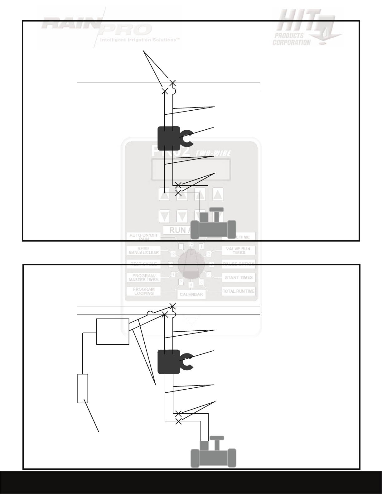
FIELD WIRING
• Ground Rod
Valve
8 PRO 2
Valve
• Branch or Tee
WWW.RAINPROCO.COM
Valve
Valve
• Branch or Tee
Valve
Valve
Valve
Page 11

VALVE WIRING
WIRE CONNECTIONS:
waterproof underground connector housing. When soldering is impractical, a waterproof
PRO 2 9
WWW.RAINPROCO.COM
Page 12
WWW.RAINPROCO.COM
Field Wires
• PRO 2 Decoder
• Red Wires
• Black Wires
VALVE WIRING
• Wire Connections
Field Wires
• PRO 2 Decoder
• Red Wires
LP-SPD-F
• Ground Rod
Red Wires •
• DBC-BR-Connectors
• Black Wires
• Wire Connections
VALVE WIRING WITH LP-SPD-F
10 PRO 2
WWW.RAINPROCO.COM
Page 13
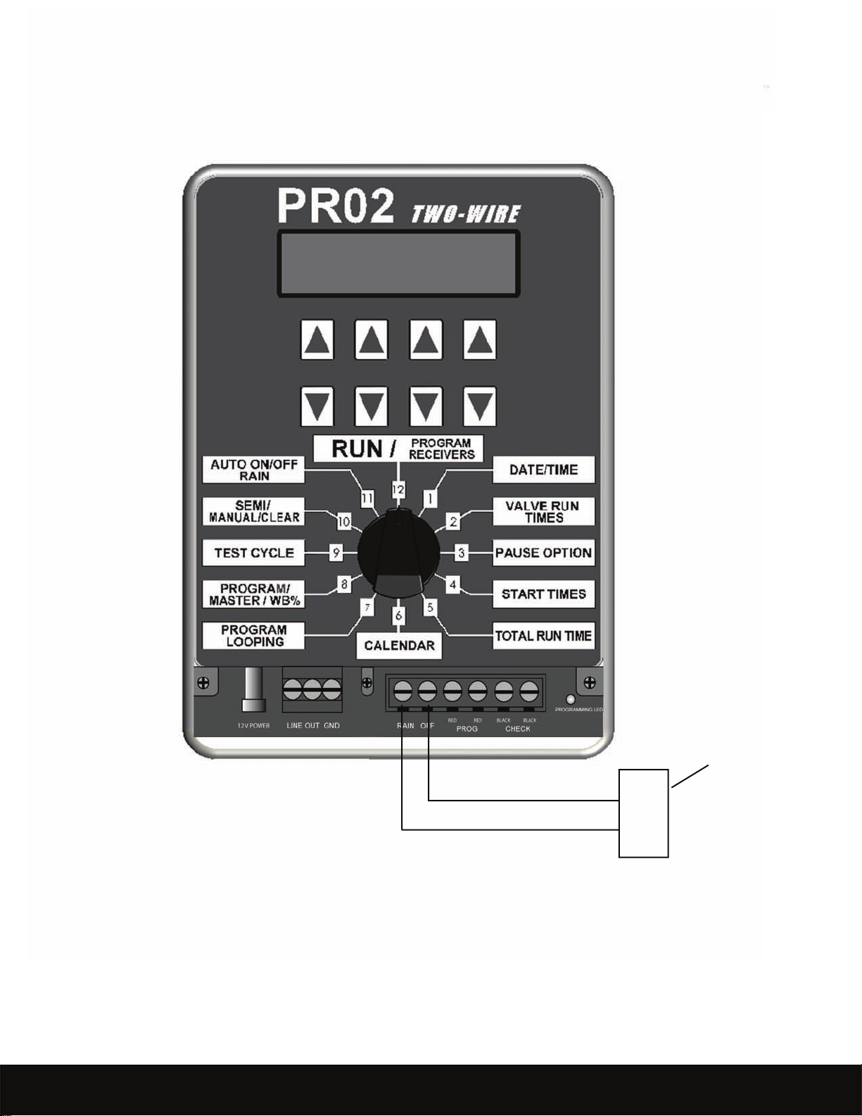
RAIN SENSOR
• Rain Sensor
Use Common (C) and
Normally Closed (NC)
NOTE: See Rain Sensor in Programming
Section to Activate Rain Sensor
Capability.
PRO 2 11
WWW.RAINPROCO.COM
��
Contacts.
Page 14
12 PRO 2
WWW.RAINPROCO.COM
will set A.M. or P.M.), use set 3 to set minutes, use set 4 to “Zero out” seconds.
valve run times can be set in hours and minutes. The maximum run times can be set
from 1 minute to 10 hours and 59 minutes on all programs except 6, which can be set for
A maximum of any 2 decoders/valves (any combination) may be operated simultane
WWW.RAINPROCO.COM
Page 15

Refer to Diamond settings at the end of this programming guide for full details.
Refer to Diamond settings at the end of this programming guide for full details.
will change in this position, but in position 2, the valve run times will stay as inputted. The
PRO 2 13
WWW.RAINPROCO.COM
Page 16

14 PRO 2
WWW.RAINPROCO.COM
(start),
or
for each day of the calendar.
The
for ODD/EVEN use the set 2 buttons to scroll to the ODD/EVEN display use set 3 or set
4 buttons to turn ODD/EVEN ON/OFF. Rotate the dial when selection is made.
The number of days that the calendar automatically sets up is determined as fol
WWW.RAINPROCO.COM
Page 17

Any valve run times and start times set in program 6 can be looped if desired.
Looping will run a program continuously for the amount of
PRO 2 15
WWW.RAINPROCO.COM
Page 18

16 PRO 2
WWW.RAINPROCO.COM
valve or pump start ON or OFF during the program running, use set 4 to increase or de
will not change in the display but the actual run time will be increased or decreased by
The water budget is the fourth leg of the Diamond Settings (see page for more on
for the test cycle.
At the conclusion, the controller will revert to automatic after 30
Within 30 minutes after the conclusion of the selected program the controller will
Water Budget 0% - 250%
WWW.RAINPROCO.COM
Page 19

— Press set 3 to activate manual mode, use set 1 to choose the specic valve
will immediately be activated for that period of time. Leave the dial in number 10 posi
At the conclusion, the controller will
You can activate up to 4 valves at the same time in manual mode.
will clear all the information in the controller by way of the following: Turn
(controller will not run for the number of days set) press set 1 for the num
To set the Controller to recognize a Rain Sensor use set 3 button to set to
To set the Controller to recognize a Rain Sensor use set 3 button to set to
Auto Functions
Use Set 4 buttons. When OFF No Auto Functions will occur. The Man
PRO 2 17
WWW.RAINPROCO.COM
Page 20
18 PRO 2
WWW.RAINPROCO.COM
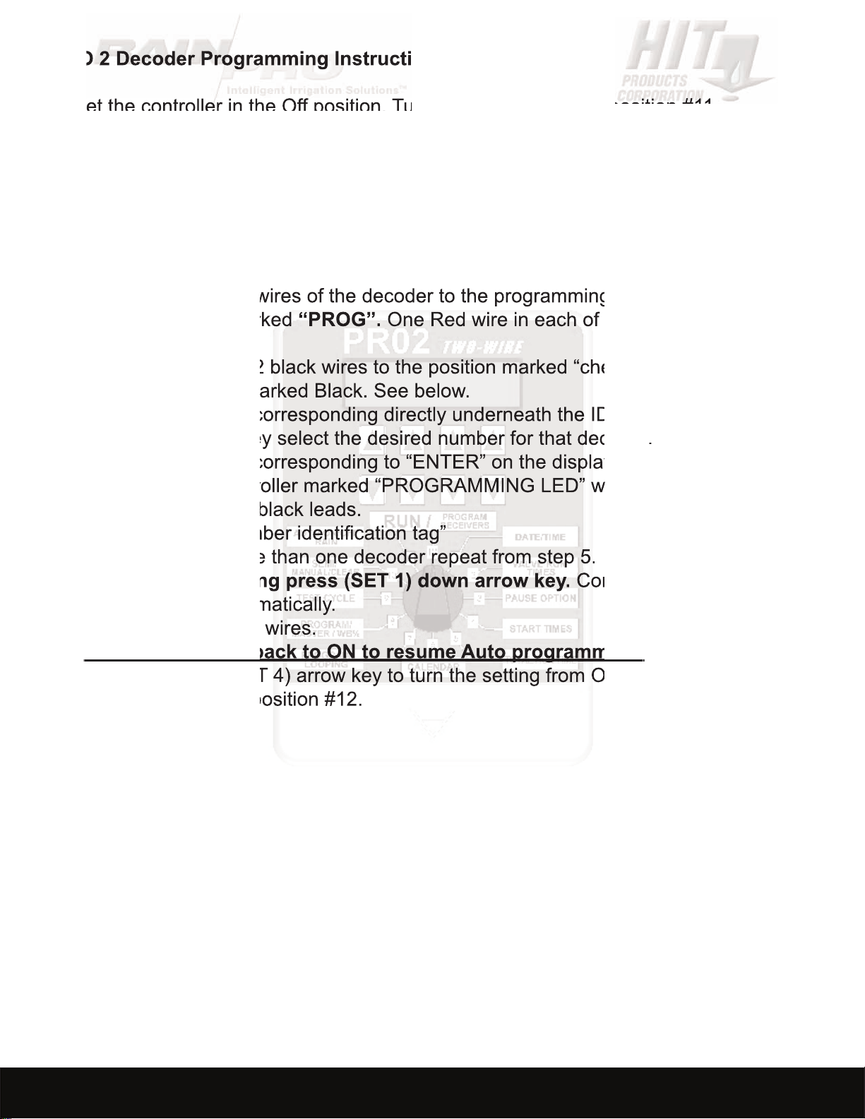
4. Press (SET 1) arrow key up to access the Set Decoder ID screen.
One Red wire in each of the Terminals
4).
Controller will
Rotate the dial to
WWW.RAINPROCO.COM
Page 21

Step 4
Step 1
Step 3
Step 2
Step 5
Step 8
Step 7
Step 6
RED
BLACK
PRO 2
DECODER
DECODER PROGRAMMING
PRO 2 19
WWW.RAINPROCO.COM
Page 22
20 PRO 2
WWW.RAINPROCO.COM
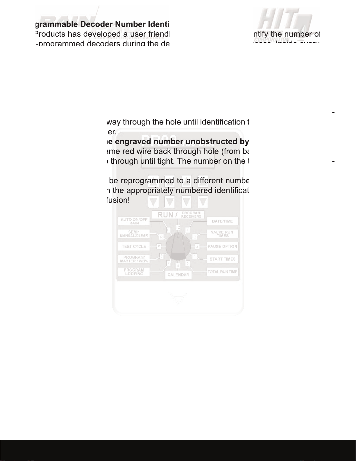
eld-programmed decoders during the decoder programming process. Inside every box
You will use these decoder identication tags as follows:
front to back) to the left of the appropriate numbered tag as you are looking at the num
4. Should decoder ever be reprogrammed to a different number, make sure to replace
WWW.RAINPROCO.COM
Page 23

if
And so on; please note that any calendar not divisible by 7 will run on different days of
PRO 2 21
WWW.RAINPROCO.COM
Page 24

22 PRO 2
WWW.RAINPROCO.COM
When the controller is activated by either “Auto” programming or a “Manual” Input, the
• If excessive current draw is sensed at a programs initial start a “
will be displayed.
• If excessive current draw is sensed during a specic valve run time
then “Short Valve” with a valve number will be displayed.
will retry after 20 minutes. Turning the dial out of “Run” and back will clear
will stay displayed during that specic valve’s run time. The controller will
“Short Valve ” due to line loss.
WWW.RAINPROCO.COM
Page 25

PROBLEM SOLUTION
tions. Correct as needed
Water budget set at zero
to field wires of a second controller
the last valve working and the first valve
tion from Controller to Rain Switch
with a valve number
and solenoid
Valves Turning ON/OFF during run time Possible EMF interference
PRO 2 23
WWW.RAINPROCO.COM
Page 26

24 PRO 2
A
regardless of wire
with a maximum 350 mA inrush and a maximum 250 mA holding current at 24VAC.
WWW.RAINPROCO.COM
Page 27

Page 28

© 2008 HIT PRODUCTS CORPORATION
 Loading...