

HiTi Digital P110S Service Manual

CONFIDENTIAL 1
P110S
Service Guide
Version: 1.11

CONFIDENTIAL 2
Revision History
Date Revision Description Remark
2009/10 1.0.0 The first edition.
2010/6/25 1.0.1 1. Disassmbly out of warranty warning
2. Modified Error code list
Page 19
Page 59
2011/1/6 1.0.2 Disassmbly warning Page 19
2012/2/8 1.1 1. Added jitter pitch (interval)
2. Modified the Capstan Roller Info
Page 60
2012/4/11 1.11 Added precaution for TPH assembly Page 54

CONFIDENTIAL 3
Outlines:
CHAPTER 1: INTRODUCTION.......................................... 4
CHAPTER 2: SPECIFICATIONS ........................................ 5
CHAPTER 3: OPERATION THEORY................................ 6
CHAPTER 4: DISASSEMBLY & ASSEMBLY ................. 19
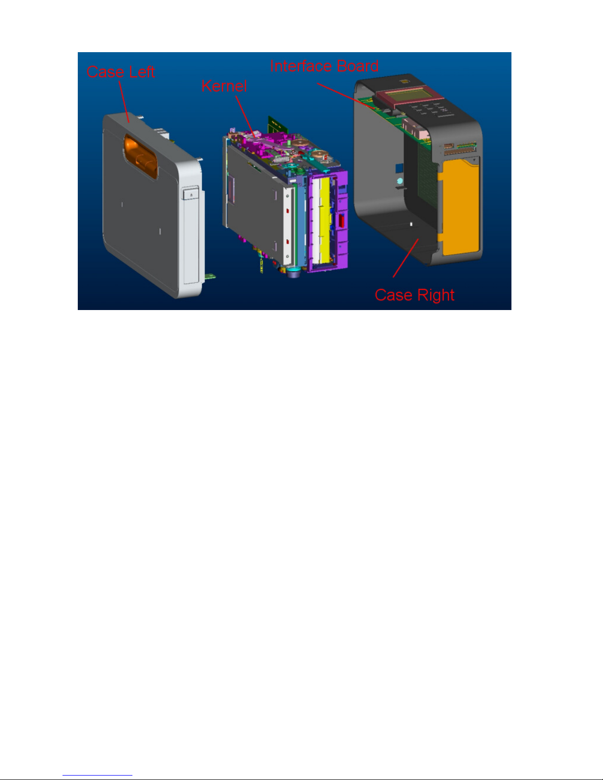
ASSY_CASE_LEFT, ASM_ID_CASE_RIGHT, CHASSIS ASSY .....20
LCD PANEL BD, ASM_LCD................................................................23
CARD BD ..............................................................................................25
MAIN BD...............................................................................................27
SMART CARD BD ................................................................................28
WIRE SNR JAM P110S.........................................................................30
WIRE SNR RIBBON P110S..................................................................32
WIRE SNR CAM P110S........................................................................33
WIRE MB TO SMART_CARD BD P110S ...........................................35
WIRE SNR RIBBON_TYPE P110S......................................................36
WIRE SNR PAPER_OUT P110S...........................................................38
WIRE SNR LE P110S ............................................................................40
ROLLER_CAPSTAN_TUK_P110........................................................45
ASSY ROLLER PINCH ........................................................................46
FAN 4010 12VDC ADDA 2-BALL SYSTEM ROHS ...........................48
MTR CAM PM 15 22OHM BIP P110S .................................................50
MTR PM 3.75 7OHM BIP P110S ROHS...............................................51
TPH 300DPI P110S TSB 6.3-DEGREE ROHS .....................................53
CHAPTER 5: ADJUSTMENT ............................................ 55
CHAPTER 6: GEAR LIST .................................................. 57
CHAPTER 7: ERROR MESSAGE..................................... 60
CONFIDENTIAL 4
Chapter 1: Introduction
This document contains
operation theory and
parts replacement procedure
s that are
intended
to ease the task of transportation, usage, maintenance and parts replacement.
CONFIDENTIAL 5
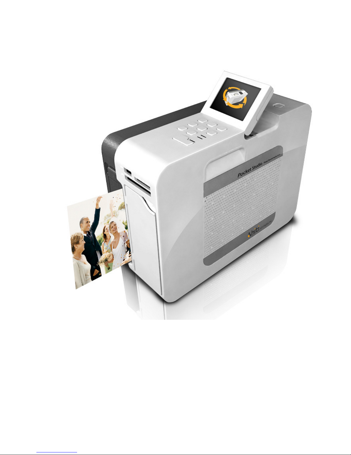
Chapter 2: Specifications
Item Description
Resolution
300 x 300 dpi
Max Prints Size
4 “x6 “
Printing time/ size
63 sec./ 4”x 6” photo paper and 1x1 sticker
Capacity
60 pieces
Ribbon Capacity
60 images for YMCO
Display
2.5” LCD 320x240 pixel
Memory Card Slot
CF Type I & II / SD / SDHC / MS / MS Pro / MMC / Micro Drive
Dimension & Weight
25cm (D) x 18.5cm (H) x 10cm (W) & 2.2 kg (excl. consumable,
battery & adapter)
File format support
JPEG
USB Host
USB mass-storage device support, PTP/PictBridge support
Computer Interface
USB 2.0 full speed interface with PC
LED Indicator
3 LED indicator (Printing, Charge, Error status)
Power Supply
100~240V Universal Power with 24V/90W Adapter
Support OS
Win2000/XP/VISTA, MAC OS x10.2 with Pentium PC
Bundle Software
ID quick désirée / ID Creator / eFrame convertor
Accessory option
Clean Kit, Battery, Carrying Bag
Power Consumption
Power Test Battery Sleep Mode <0.1W
Normal Sleep Mode <10W
Full load Mode <90W
Documentation & Configuration
(1) P110S x1
(2) 1.5m USB cable x1
(3) Clean Kit x1
(4) 3 M Power cord with adapter x1
(5) Driver, AP and electrical manual CD x1 in 10 languages
(6) Quick installation guide x1
(7) Warranty Card x1
CONFIDENTIAL 6
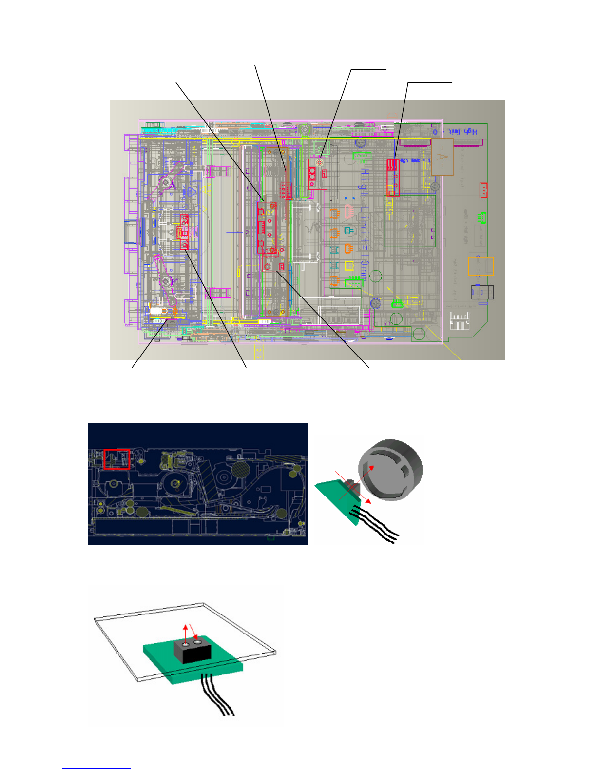
Chapter 3: Operation Theory
Hardware
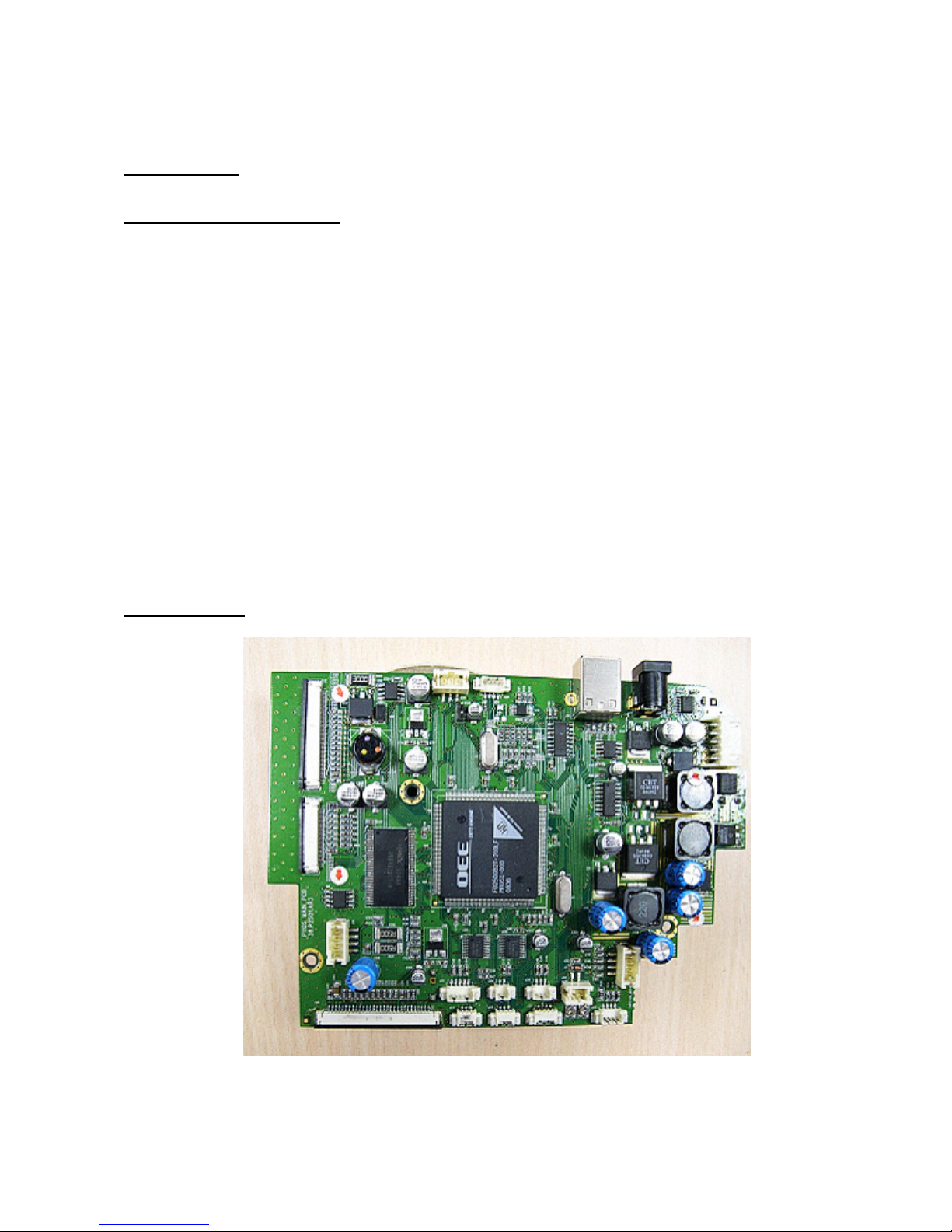
P110S Circuit Theory
The circuit of P110S contain six parts: main board, card board, LCD board, motors and sensors
wires/cables. The power is supplied by adapter and Li-ion battery. Adapter is an AC to DC power
conversion device and it provides a 90W max. 19V, DC source to drive P110S photo printer. And the
Li-ion battery is five series-one parallel (5S1P) and the capacity is 2600 mAH. The voltage of battery is
from 21V (Full) to 13.75V (cutoff). And the normal voltage of battery for printing is from 21V to 18V.
Main board transforms (step-up) adapter or battery voltage to 24V for motors driver ICs and charger IC,
and also transforms (step-down) the input voltage to TPH necessary voltage (15V +/- 5%). In the mean
time, transform input voltage to 5V and 3.3V by voltage regulators for ASIC, Memory, and the I/Os. Main
board provides a connection to thermal print head, supports both Toshiba G5004 series. To the others, CF
card socket provides an interface for CompactFlash type, including CF type I, CF type II and MicroDrive;
MultimediaCard,SecurityDisk, and MemoryStick, are integrated in 4 in 1 card socket. Card board, which
consists the driver IC for the 2.5-inch TFT-LCD panel, the user buttons, and the control circuit, is to be
the user interface(UI). The input voltage from adapter or battery and the video signal from main board are
connected to card board. Besides, the TFT-LCD panel is to display images and messages for user
operations.
Motors and sensors wires are builts to motivation provided and detected whicth based on main board
controlled.
Main Board
The circuit theory of main board will be divided into six parts.
1. ASIC Architecture
The FD2500 (code name: Nexus), the successor of FD2680 (code name: ULTIMA), is a single-chip
integrated controllerfor the dye-diffusion thermal transfer photo printer and multimedia applications
based on a turbo 8032micro-controller, a fixed-point DSP, an Image Extension (iMX) data processing
accelerator, and an intelligent print engine. The Nexus engine is specifically designed for the digital
processing of imaging applications, and the dual cores (MCU-DSP) architecture provides benefits of
CONFIDENTIAL 7
parallel processing of control and computation operations, and the unified memory architecture (UMA)
eliminates the memory cost. Besides, versatile general peripherals are also to provide the data
communication capability.
2. Memory IC
a. SDRAM
This 256Mbit SDRAM on main board is to be the data buffer. The image file, print data, video frame
are temporarily stored during operation.
b.NOR Flash
This 8Mbit flash memory is applied as respective ASIC need which store the MCU code, the DSP
code,the logo, the OSD (On-Screen Display) map and etc.
c.NAND Flash
This 128MB flash memory is to store image related data for later image compounded using.
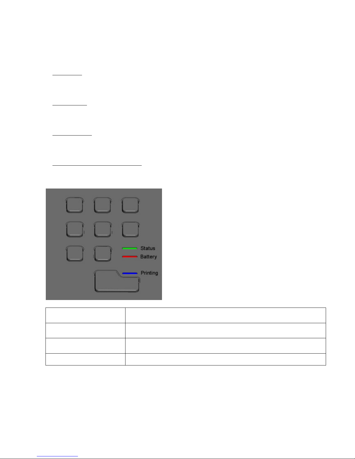
3. LED & Sensor
a. Status/Error LED/Indicate LED
Show printer status and error message. Green LED shining means printer ready. Green LED blinking
means printer busy. Rde LED blinking means error message. Orange LED shining means battery
charging. Blue LED blinking means push the print button. Blue LED shining means printing.
Printing LED (Blue)
On : Printing
Blinking : To hint user click the print button to print
Battery LED (Red)
On : Charging
Blinking : Battery low
Error status LED (Green)
On : Printer is ready for processing job
Blinking : Printer is processing job, or in power-up initialization state
Error status LED (Red)
Blinking : Indicate error
CONFIDENTIAL 8
b. Cam sensor
Cam sensor (2 pcs) indicates the position of linkage. There are four position: P1-initial position,
P2-Load paper position, P3-ribbon search position, P4-print position.
Penetration Type Sensor
c. Paper out/ LE/ Jam sensor
Detect paper in paper cassette, Detect the existence of paper and paper length.
Reflective Type Sensor
Paper out sensor
Jam sensor
Smart card sensor
Ribbon sensor
Ribbon type sensor
LE sensor
Cam sensor
CONFIDENTIAL 9
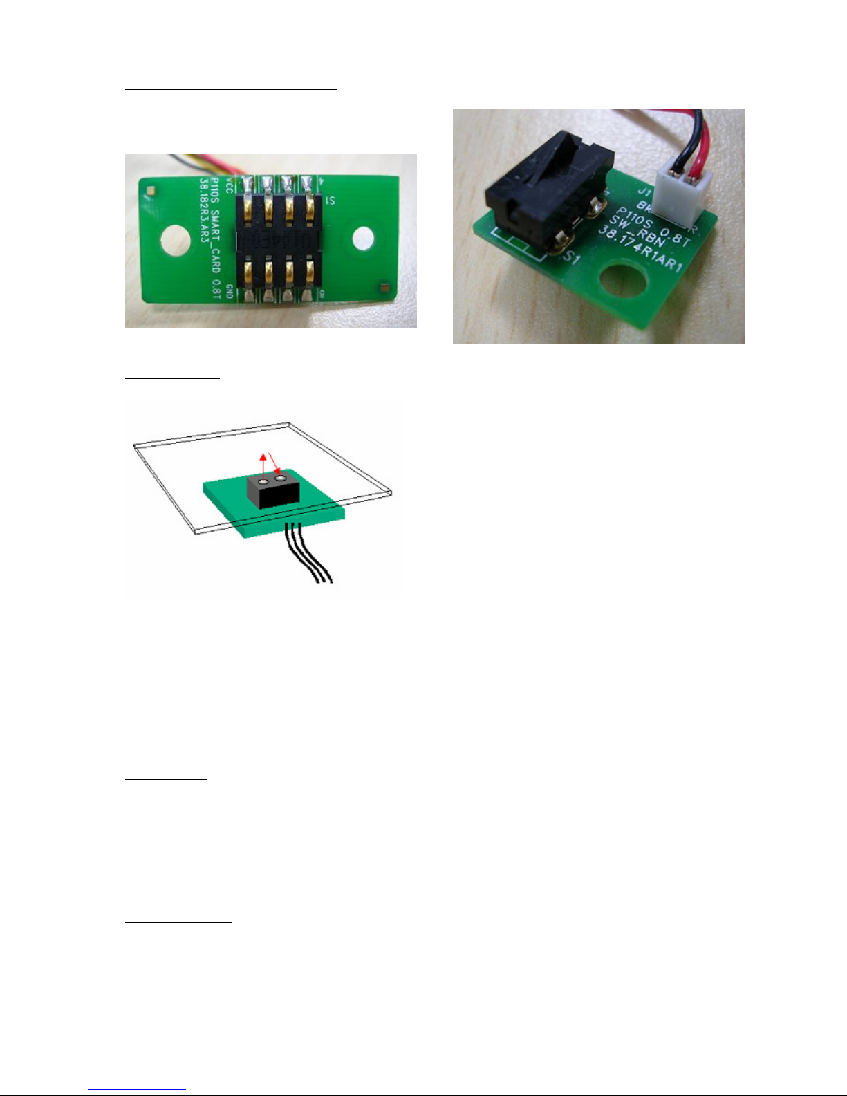
d. Smart card/ Ribbon type sensor
Detect ribbon type and sheet and whether the ribbon install.
e. Ribbon LED
Detect ribbon color Y, M, C and O, which are index as black bar individually.
Reflective Type Sensor
4. TPH Interface
Print data will be shifted into TPH during each clock. After 256 shift clocks, one line data will be
shifted to TPH. Latch/ signal will latch the print data. Strobe/ signal will heat the corresponding heater
elements on TPH according to shift-in data. More the storbe/ time, more the dye of the ribbon is
transferred to paper.
5. Motor Interface
a.Cam motor
Cam motor is a bipolar motor and driven by driver IC L6219. L6219 is designed to drive both windings
of a bipolar stepping motor and includes pulse-width-modulation (PWM) control of ouput current to
750mA. For PWM control, the maximum output current is determined by user's selection of a reference
voltage and sensing resistor.
It controls printing function and position of ASSY LINKAGE.
b. Capstan motor
Capsten motor is a bipolar motor and driven by driver IC L6219. L6219 is designed to drive both
windings of a bipolar stepping motor and includes pulse-width-modulation (PWM) control of ouput
current to 750mA. For PWM control, the maximum output current is determined by user's selection of
a reference voltage and sensing resistor.
It controls Takeup Roller, Feeding Roller, Ribbon Take, Ribbon Rewind, Paper moving
6. Charging Interface
CONFIDENTIAL 10
Charging IC is MAXIM1640. There are three charging modes Top-off mode, Fast-charge mode, and
Pulsetrickle mode. Pulse-trickle mode is for battery in over-discharge situation. Fast-charge is for
battery in normal voltage. Top-off is after fast-charge mode for charging battery voltage upto full
voltage (21V).
Card Board
The circuit theory of card board can be divided into three parts.
1. CPU and serial EPROM
This card board uses an 80-series CPU with 64KB on-chip FLASH EPROM to do central control,
including LCD backlight control, button-pushed sensing, and communication with main board. The
serial EPROM stores setting data of LCD that is got from the calibration process. CPU will read the
serial EPROM and complete the initial setting for LCD after power on.
2. LCD and backlight LED
The 2.5-inch TFT LCD panel is used to display images and messages. It's backlight is low DC voltage
ultralight white-LED.
3. Memory Card Socket and Interface
CF card socket for CF memory card, and 4-in-1 card socket for SM, MMC, SD, and MS memory cards.
And CF control by ASIC, SM, MMC, SD, and MS control by PS3002.

CONFIDENTIAL 11
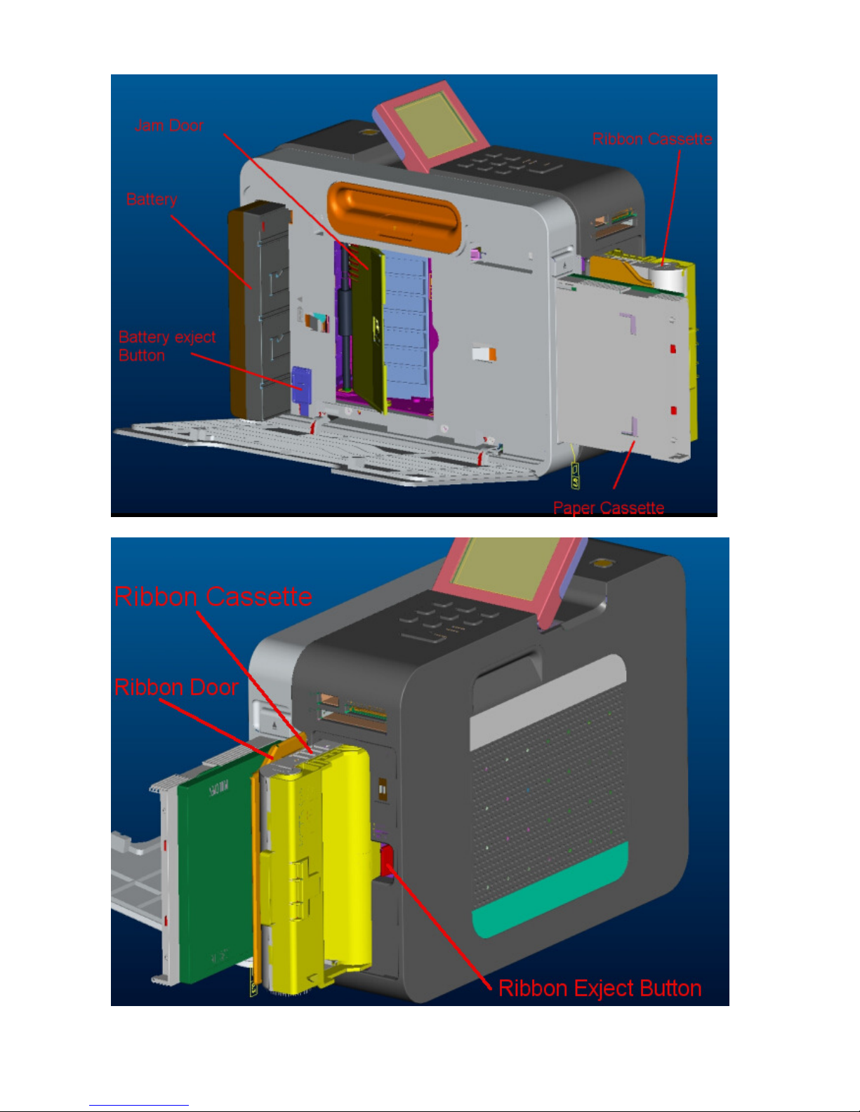
Mechanism & Movements
User Interface
CONFIDENTIAL 12
CONFIDENTIAL 13

CONFIDENTIAL 14
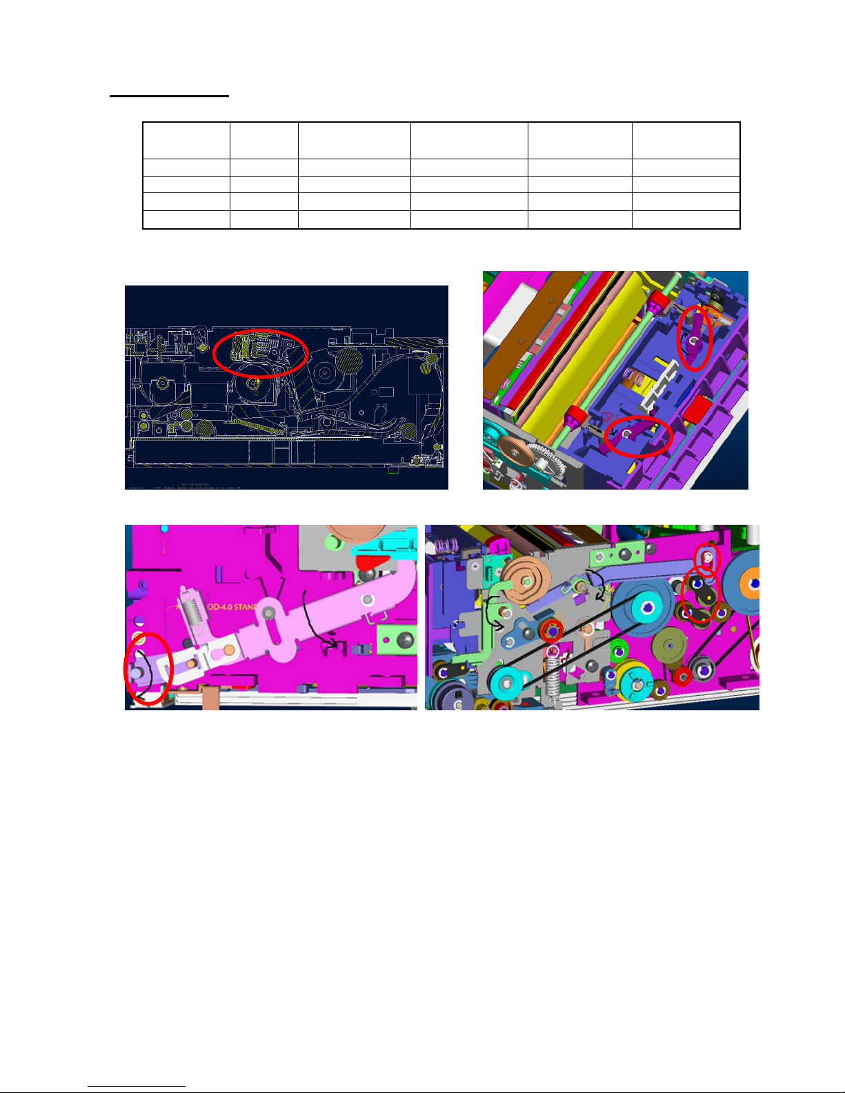
Function layout
Ribbon Lock
Module
ADF translation
parts
Supply TQL
Takeup TQL
Capstan Roller
Cam Motor
Capstan Motor
Main Board
Exit Paper gear
train
ASSY
LINKAGE
Linkage rotate axes
Lifter
Cam gear
train
CONFIDENTIAL 15
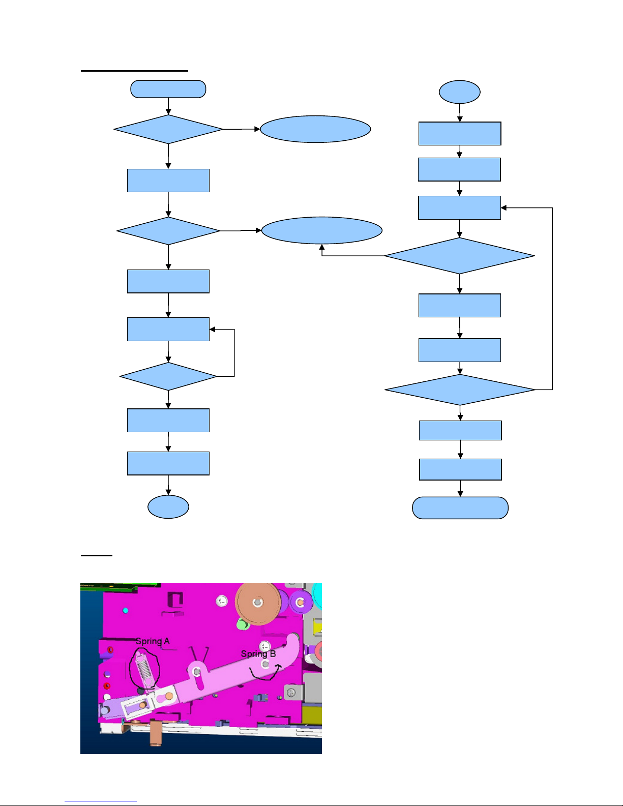
Printing Process
ADF
Spring A(500g~800g): The value too big --> Multi Feed; The value too small --> Miss Feed
Spring B(300g-cm): To make sure the lifter status is down
Search RBN Y
A
Job start
Paper exist ?
Error !!
Paper Out
Move Cam to P3
Error !!
Ribbon Out
Move Cam to P2
Paper
feeding
Sensor
Move Cam to P1
Position
Paper
A
Move Cam to P4
Print Y
Move Cam to P3
Search RBN
M,C,O
Move Cam to P4
Job finished ?
Move Cam to P1
Print
M,C,O
Exit
Paper
Job finished
CONFIDENTIAL 16
Cam Position
Function
Cam
(Linkage)
Ribbon Search
(TQL _Take)
Paper Feeding
(Roller_Pick-Up)
Paper Feeding
(Lifter)
Paper Moving
(Paper Guide)
Initial P1 Disable Disable Disable UP
Paper Feeding P2 Disable
Enable Enable
UP
Search Ribbon P3
Enable
Disable Disable Mid
Printing P4
Enable
Disable Disable Down
Initial (P1)
Ribbon cassette is released.
Lifter is down (to avoid paper feeding). Roller_Pick-Up is disable. TQL_Take is disable.

CONFIDENTIAL 17
Paper Feeding (P2)
Ribbon cassette is locked.
Lifter is up. Roller_Pick-Up is enable. TQL_Take is disable.
Search Ribbon (P3)
Lifter is down. Roller_Pick-Up is disable. TQL_Take is enable.
CONFIDENTIAL 18
Printing (P4)
Lifter is down. Roller_Pick-Up is disable. TQL_Take is enable.
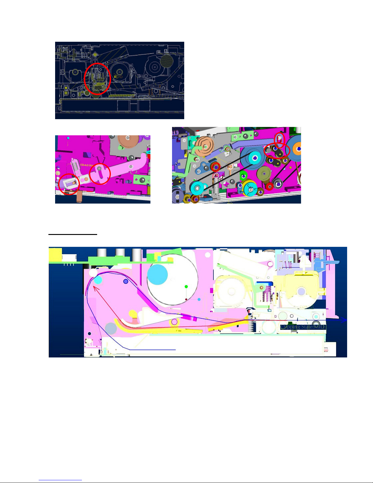
Paper path
CONFIDENTIAL 19
Chapter 4: Disassembly & Assembly
Safety Instructions
Read these instructions carefully. Save these instructions for future reference.
Follow all warnings and instructions marked on the printer.
Before disassembly, it should be off the switch and removed the
batter pack and plug of power cord. Any Main BD or Card BD
damage related to disassembly will be judged as “out-of-warranty”
after identification.
Do not place the printer on an unstable cart, stand, or table. The printer may get damaged by a
fall.
Openings in the chassis and the bottom are provided for ventilation purposes and to ensure
reliable operation of the printer by protecting it form overheating: these openings must not be
blocked or covered.
Placing the printer on a bed, sofa, rug, or other similar, not firm surfaces may block the openings.
The printer should never be placed near or over a radiator or heat register, proper ventilation and
cooling must be provided at all times.
The printer should only be operated with the type of power indicated on the marking label. If you
are not sure of the type of power available in your area, consult your dealer or local power
company.
If an extension cord is used with this product, make sure that the total ampere rating of the
equipment plugged into the extension cord does not exceed the extension cord ampere rating.
Also, make sure that the total rating of all products plugged into the wall outlet does not exceed
the fuse rating.
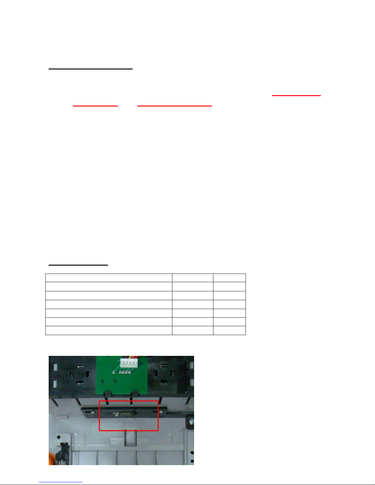
Tools Required
Name Model Q’ty
Screwdriver
- 1
Screwdriver (small)
- 1
Flat-blade screwdriver (small)
- 1
Spring hook
- 1
Nipper
- 1
Pliers
- 1
Please assemble carefully to avoid breaking two notches.
 Loading...