

HiTi Digital 640PS, 641PS Service Manual

Confidential
1
64xPS/ID
Service Guide
Version: 1.1
The Service Guide was written mainly for engineers.
Please Do Not reproduce and duplicate.

Confidential
2
Chapter 1:
Overview
Chapter 2:
Theory of Operation, Mechanism, Firmware
Chapter 3:
Disassembly, Index of Parts, Tools required
Chapter 4:
Adjustments
Chapter 5:
Contact Information
Confidential
3
Chapter 1: Overview
Overvie w
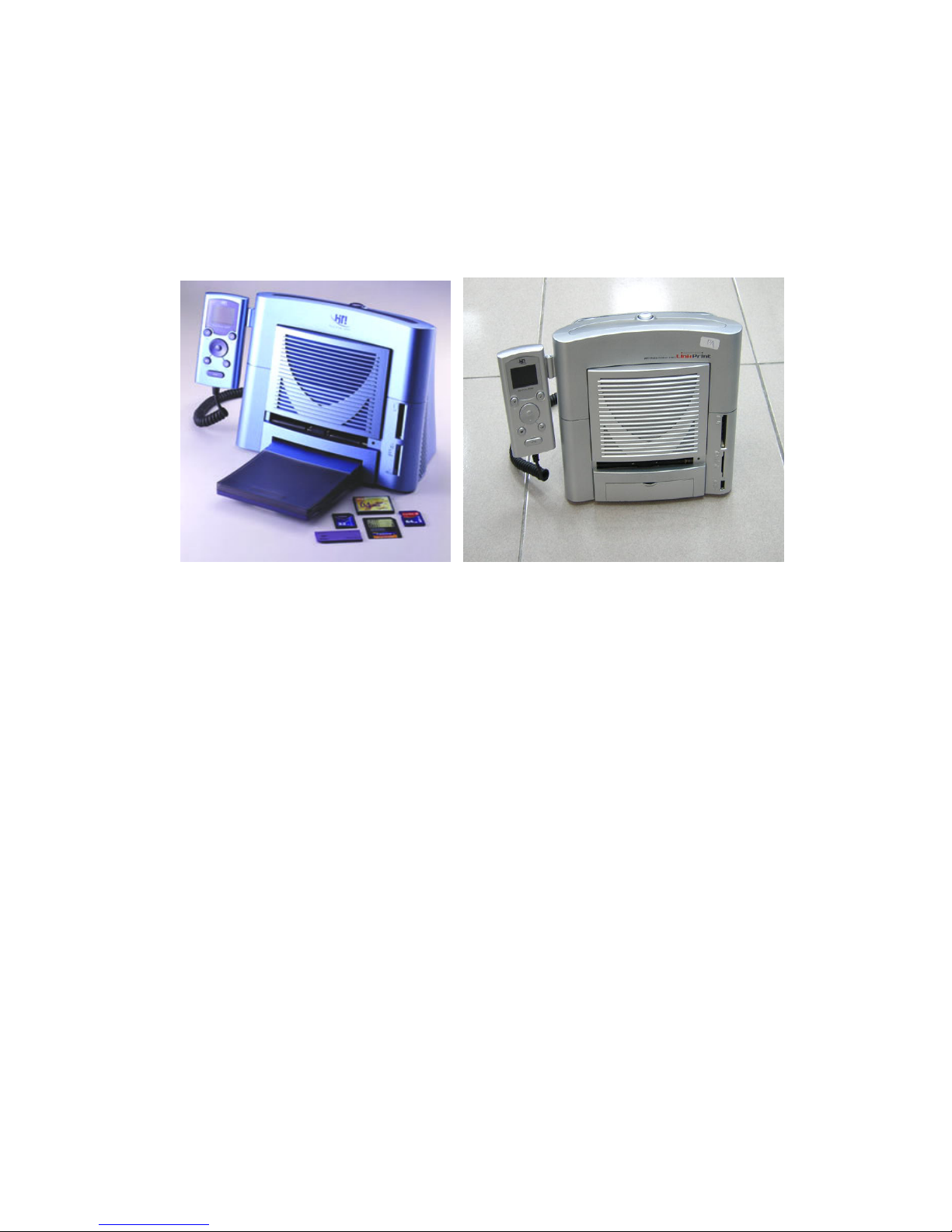
HiTi Photo Printer 640PS and 641PS are popular printers able to print in high-speed &
high-quality. HiTi p hoto printers are sty lish and compact. HiTi printers can print 6x4”
(10x15cm) photos, ID photos (various sizes), name cards, post cards, greeting cards,
season cards, calendars, and stickers.
There are 2 different ways to operate the HiTi Photo Printer 640PS and 641PS:
1. The printer can be connected to a personal computer via a USB cable. HiTi photo
printers meet the USB 1.1 standard and are fully compatible with any USB device (USB
1.0 to 2.0).
2. The HiTi Photo Printer 640PS and 641PS can also be operated without a direct or
indirect connection to a personal computer. This printing style is called standalone
printing. In this mode, images are being selected with the handheld TFT monitor. The
640PS and the 641PS both feature ‘onboard’ multi-card readers. A memory card can be
inserted into the card slot. Image can be selected on the handheld TFT monitor.
In addition to a multi card memory card slot, the 641PS also features a LinkPrint
connector. LinkPrint is an advancement of the Picture Bridge standard, which allows
compliant cameras to be directly connected to the 641PS printer. LinkPrint also allows
external hard drives or storage drives, such as USB memory sticks, to be directly
connected to the printer.
The 640PS and 641PS include one of the following functions:
Printing Process
640PS
641PS

Confidential
4
YMCO 4 passes (Yellow, Magenta, Cyan, and Over-coating)
Over coating ensures that HiTi’s printouts can be kept a longer time than inkjet
printer’s printouts.
High Quality Resolution
640PS and 641PS: 403x403 dpi
Convenience
All HiTi Photo Printer ship with “Photo Desiree”, a photo editing program
designed for printing 4”x6” photos, id photos, calendars, photo name cards, and
photo greeting cards.
HiTi “Photo Desiree” enhances and enables very easy usage for your photo
printer. It allows you to turn your 640PS or 641PS into a digital mini lab you
can operate from home.
You can download the latest firmware and other software from the HiTi website
to your computer. Firmware is being updated per USB cable.
Multi-memory card support. HiTi Photo Printer 640PS and 641PS p rovide two
types of memory card slots.
Stand-alone operation & PC link: You can instantly p review what you want to
print.
640PS and 641PS can be used to read y our images from a memory card (it has
the functions of a card reader).
(641PS onl y:)
641PS can accept any USB device (Camera, USB memory stick, USB memory
card adaptors, External HDD). This technology is known as LinkPrint.
Specifications
Model Name HiTi Photo Printer 640PS & 641PS
Printing Method
Dy e Diffusion Thermal Transfer continuous tone
printing
Gradations
256 levels per Yellow, M agenta, Cyan color (8 bits),
total 16.77 million true colors
Resolution 403×403 dpi
Paper Size 4 in.×7 in. with detachable boundary
Printing Size 4 in.×6 in., (100mm×152mm)
Paper Fe e d Cassette type automatic feeder, 25 sheet capacity
Printing S peed
Approx. 60 sec. per sheet (excludin g data transmission
time)
Operating Temperature 59˚ ~90˚F (15˚ ~32˚C)
Operating Humidity 20 ~75% RH
Computer Interface USB Ver. 1.1
Card S ocket
Twin slot support CF, SM, SD, MMC, MS and Micro
Drive
File Format Support EXIF, JPEG, DPOF
Power Supply 100~240V, 50/ 60 Hz
Confidential
5
Operating Syste m
Windows 98/ ME/ 2000/ XP
Linux & Mac OS 10.2 and above
Mi nimum S ystem
Requireme nt
Win 98/ME: 64MB RAM , Pentium PC
Win 2000/ XP: 128MB RAM, Pentium PC
Certification UL, TUV-GS, FCC, CE, BSM I, CCC, C-Tick, VCCI
Accessories Included
Paper Cassette, USB cable, CD-ROM (with printer
drivers, bundle software and electronic manual), AC
power cord, Sample print kit (8 sheets of photo paper,
1 sheet of 4×4 sticker, 1 sheet of 4/2/4 sticker plus 1
YMCO ribbon cartridge for 10 prints
Chapter 2: Theory of Operation
Dye Diffusion Thermal Transfer (D2T2)
Dye Diffusion Thermal Transfer (D2T2), the world’s leading technology in photo
printing processes, uses a thermal printing head (TPH) to sequentially heat three ribbon
panels that are coated with yellow, magenta and cyan dye. The heat process turns the dye
into gas that diffuses into a thin receiving layer on top of the paper. An overcoat is then
layered down on top of the paper to protect the color against water and ultraviolet rays
and to prevent it from fading.
Compared with some other photo-capable printing technologies, such as Thermal
Autochrome (Fujifilm), Variable Dot (Fujicopian) and Inkjet (Canon, Epson and HP),
Dye Diffusion Thermal Transfer creates the most realistic photo quality. To the naked
eye it is indistinguishable from photographic prints. Its continuous-tone printing produces
256 color gradation levels in each p ixel independently while other technologies, like
Variable Dot and Inkjet, have to make different dot sizes to increase the resolution in
half-tone to achieve similar effects.
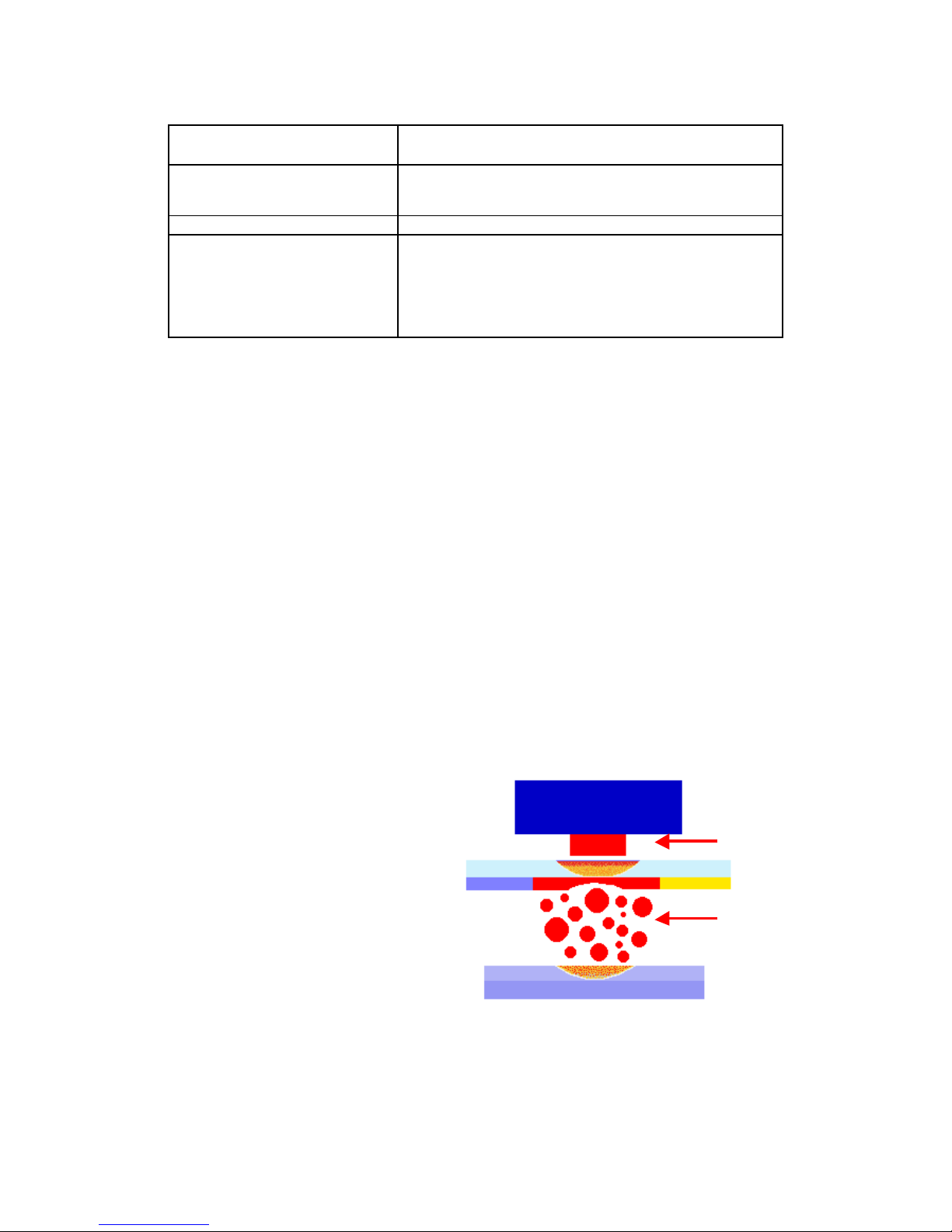
The Thermal Print Head (TPH)
sequentially heats three ribbon panels
that are coated with dye in yellow,
magenta and cyan. The heat process
turns the dye into gas that diffuses into
a thin receiving layer on top of the
paper. An overcoat is then layered
down on top of the paper to p rotect the
color against water and ultraviolet and
to p revent it from fading.
TPH
Paper
Ribbon
Heat
Dye
Confidential
6
Hardware
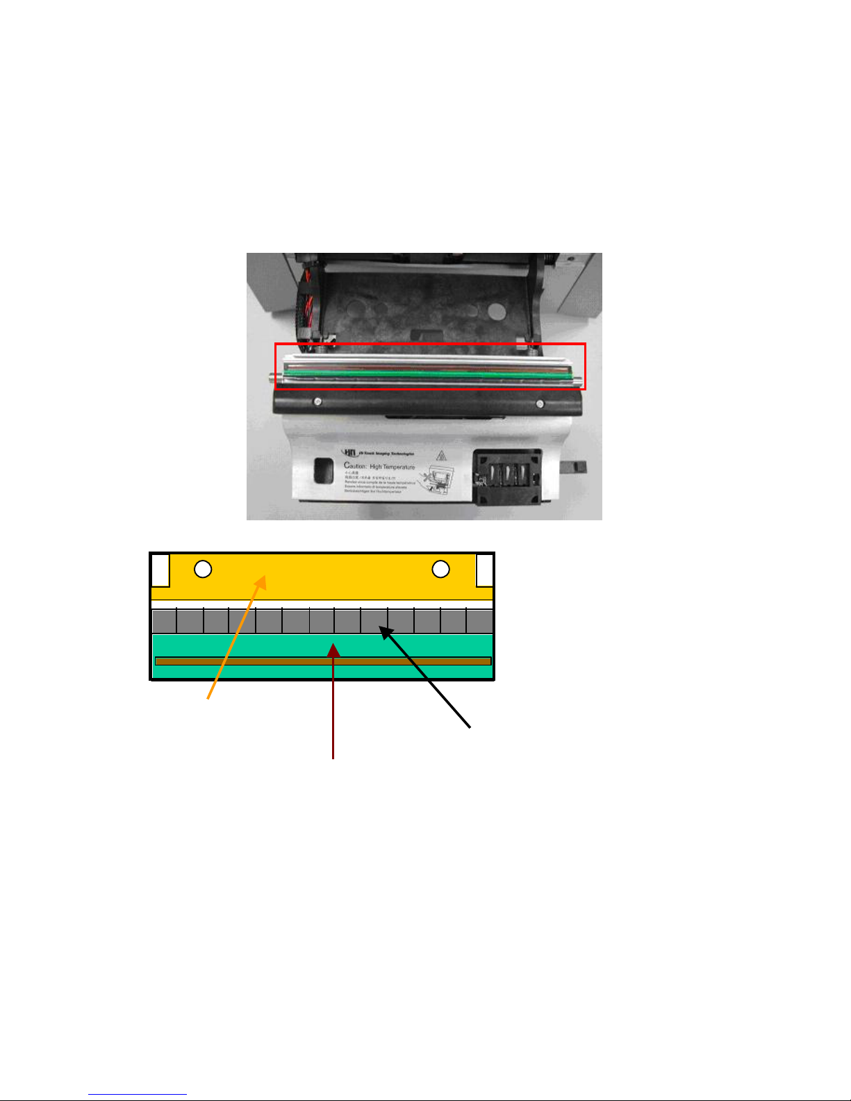
Therma l Print Head (TPH)
Thermal Print Head (TPH) is the key component for D2T2 printer, like the inkjet printing
head for inkjet printer.
Heating Ele ment
Driver IC
PCB
Confidential
7
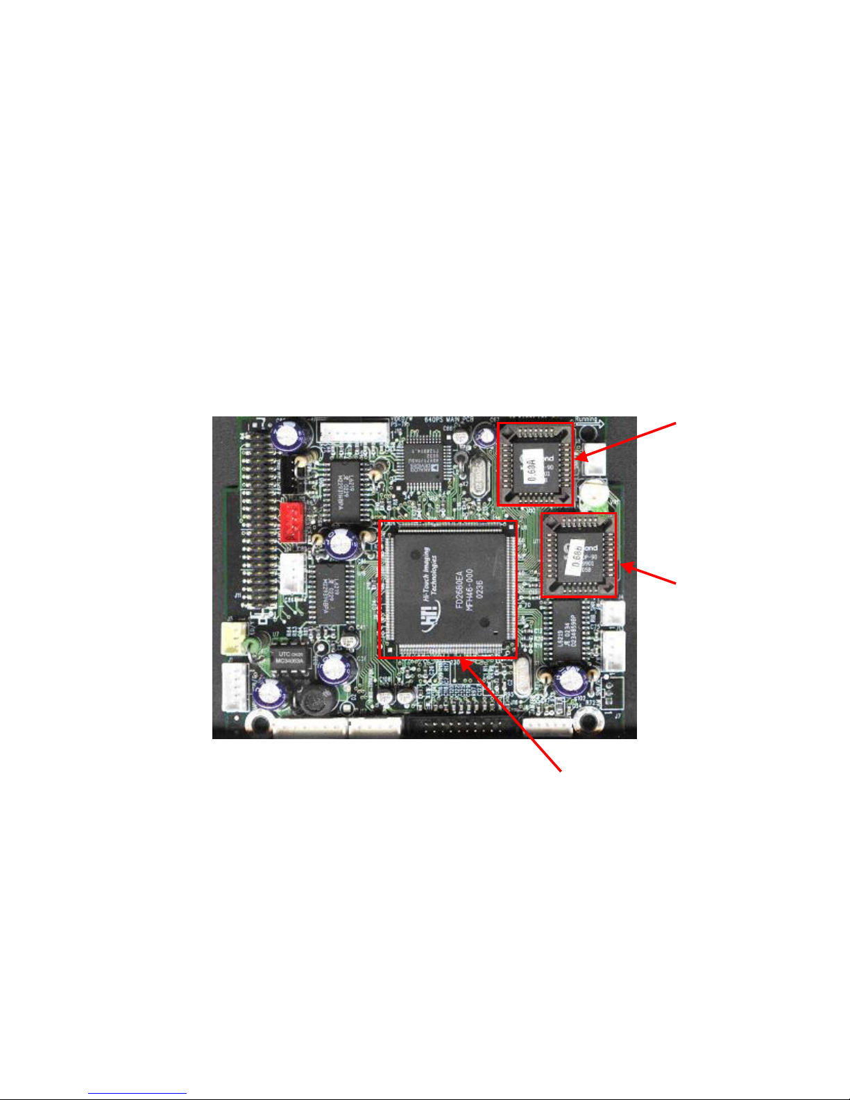
Main Board & ASIC
Note: Main Board = Mother board; ASIC = HiT i CPU
The ASIC is an IC (Integrated Chip) located on the Main Board. The ASIC was designed
by the HiTi R&D dep artment and features an 8032 MCU. The ASIC drives the USB
controller, controls the embedded SDRAM, MCU I/F, USB I/F, memory I/F, and GIO
interface.
The Firmware (located on IC-A and IC-B) controls the actions of the printer by reading
and writing the registers. Please note IC-B is a back up to IC-A.
The VR (Variable Resistance) on the main board is used to adjust the voltage of the
ribbon sensor. (M ore details located in the VR adjustment section).
The 640PS and 641PS have 2 ICs located on the mai nboard. The FW (firmware) i s
stored in IC-A and IC-B.
The picture below illustrates the mainboard of the 640PS.
On the 641PS main board IC-B is soldered onto the main board.
ASIC
IC - A
IC - B
Confidential
8
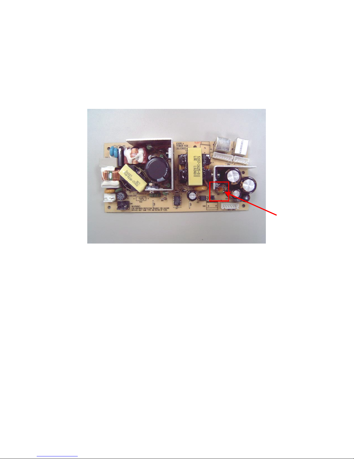
Power Board
It contains a universal AC input, DC +18V/7V outp ut and a USB interface.
The VR (variable resistance) on the power board is used to adjust the voltage of the THP.
This controls the color density of the printout.
The illustration below shows the image of a 640PS power board.
Note: If the color density is too light, a voltage adjustment (VR on the power board) can adjust the
lightness. More explanation will be given later.
VR
Confidential
9
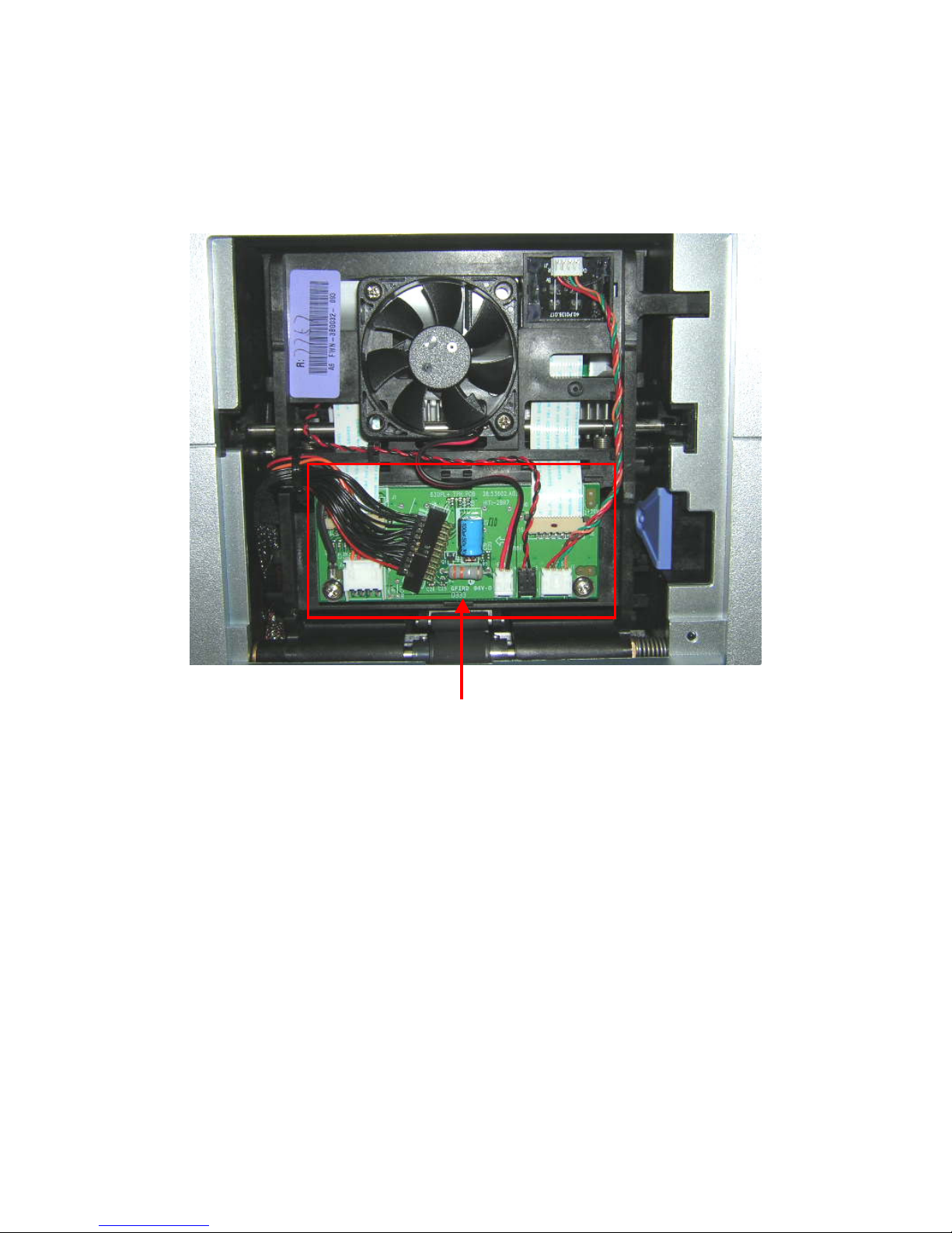
TPH Board
The TPH Board connects the cables (Ribbon LED cable, TPH Cable, Cassette Sensor
Cable, Fan Cable). The TPH board connects then to the motherboard.
TPH Board
Confidential
10
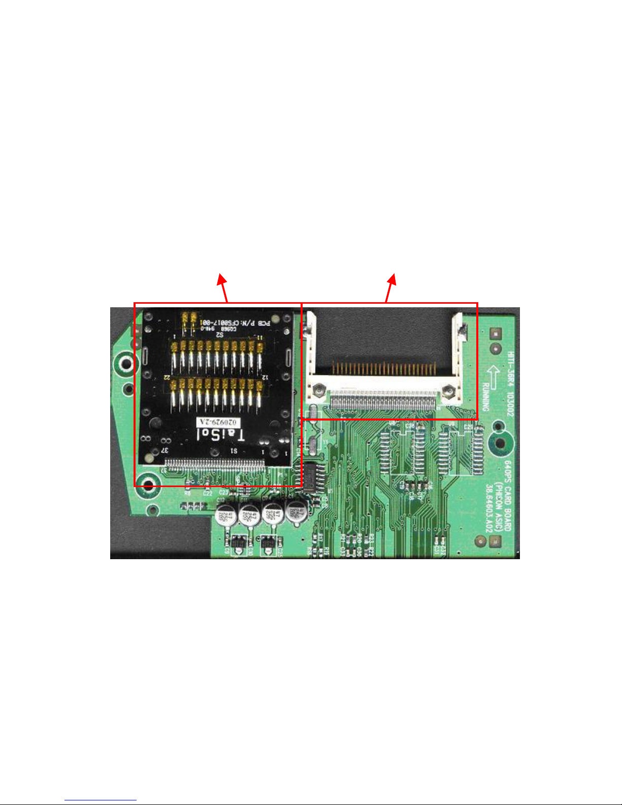
Card Board (640PS and 641PS)
640PS : There are 2 memory card sockets on the card board. One is for Compact Flash
and the other is for Smart M edia/ Multi-Media-Card/ Secure Digital Card/Memory Stick.
641PS : The 641 PS card board features an enh anced USB Connector. This USB
Connector connects Picture Bridge compatible cameras, external hard-drives and storage
cards such as USB memory sticks to the printer. As it is more advanced then Picture
Bridge it is called Link Print.
The illustration below shows the 640PS card board
Compact
Flash
socket
4 in 1 memory card
socket

Confidential
11
The illustration below shows the 641 PS card board
4 in 1 memory card
socket
CompactFlash
socket
USB DataLink
Socket
Confidential
12
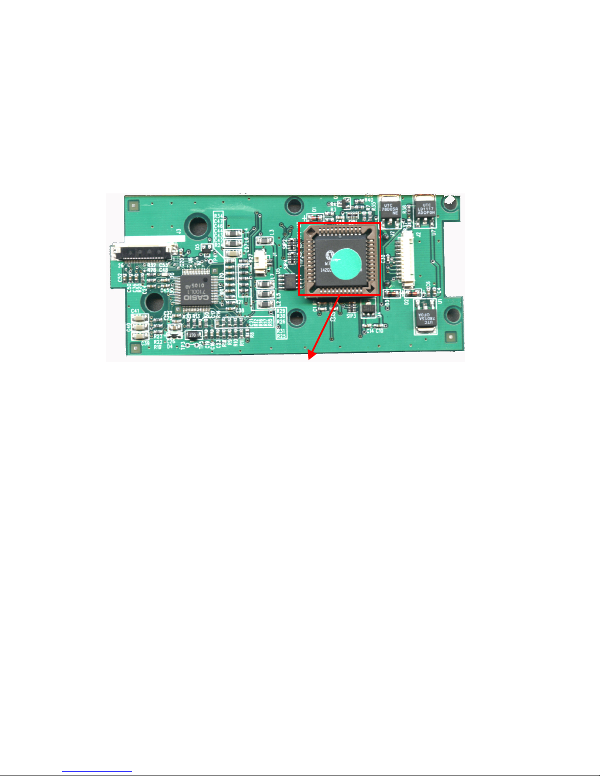
Controller Board (640PS and 641PS)
This controller board uses an 80-series CPU with 4KB on-chip FLASH EPROM for the
central control – this would include an initial setting of the LCD driver IC, the LED
backlight control, the button-pushed sensing and communication with the main board.
The serial EPROM stores the setting data of the LCD that was received at the calibration
process. The CPU will read the serial EPROM and complete the initial setting for LCD
after it has been powered on.
EPROM
Confidential
13
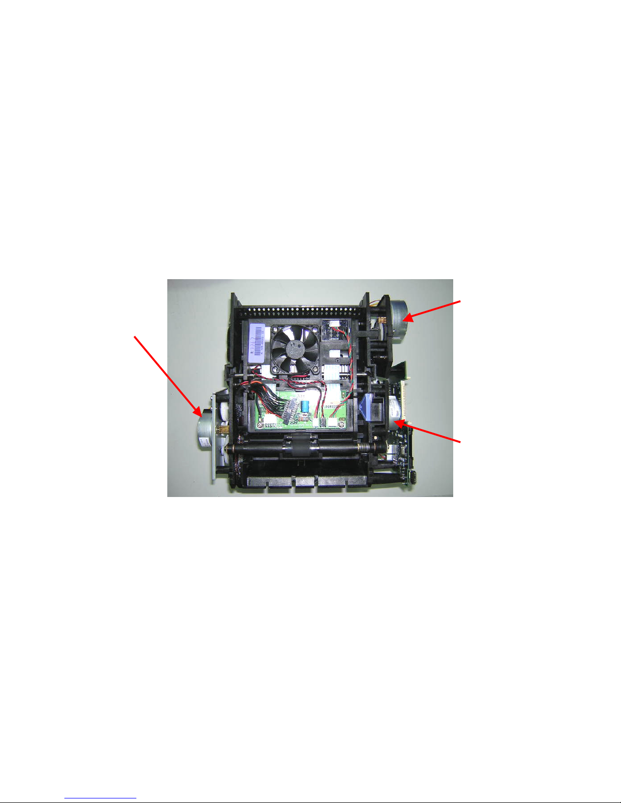
Motor
Cam mo tor
The Cam motor is a bipolar motor which ddrives the CAM to control the Platen roller’s &
Pinch roller’s position.
Capstan motor
The Capstan motor is a bipolar motor which drives the Capstan roller to control the
movement of the paper.
Ribbon/ ADF motor
The Ribbon/ ADF motor is a bipolar motor which feeds paper into the printing path and
then rolls the ribbon to the right starting position.
Cam
motor
Ribbon/ ADF
motor
Capstan
motor
Confidential
14
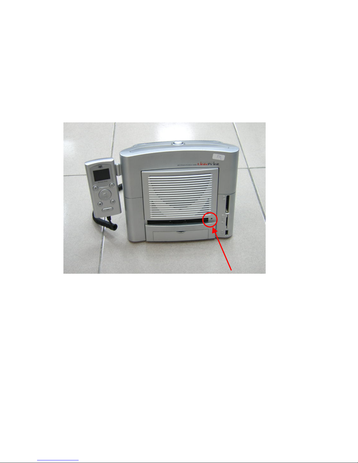
LED & Sensor Status/ Error LED
The Status/Error LED indicates the status of the printer. It also communicates any error
messages.
For example: The steadily shining Green LED indicates the ready stage of the printer.
The blinking Green LED indicates that the printer is busy. The blinking Orange LED
indicates that an error has happened.
(More in fo about Error messages later in this document)
Status/ Error
LED
Confidential
15
Cam Sensor
Depending on the printer’s status, the positions of the platen roller and the pinch roller
stay different. The Cam controls the movement of the platen roller between these
positions, and the Cam sensor detects & feeds the position’s information back to the
firmware. There are three different platen roller positions:
P1 = Initial Position
The gap between the platen roller & TPH is at
its largest, and the pinch roller is relaxed. The
printer is at this position when the printer
powers on or resets.
P2 = Loa d Position
The gap between platen roller & TPH is not as
large as at P1. The gap enables the ribbon to
wind. The pinch roller touches the capstan
roller and enables the loading of the p aper.
P3 = Print Position
The platen roller is close to the TPH,
and the pinch roller touches the capstan
roller which enables paper to move
forward and backward.
Cam
IINNIITTIIAALLLLOOAADDPPRRIINN
TT
Confidential
16
Leading Edge (LE) Sensor and Jam Sensor
The purpose of both sensors is to detect the status of paper. The sensor will be on when it
detects the loading of paper. The LE Sensor will be off if it does not detect paper loading.
Leading Edge
sensor
Jam sensor
Confidential
17
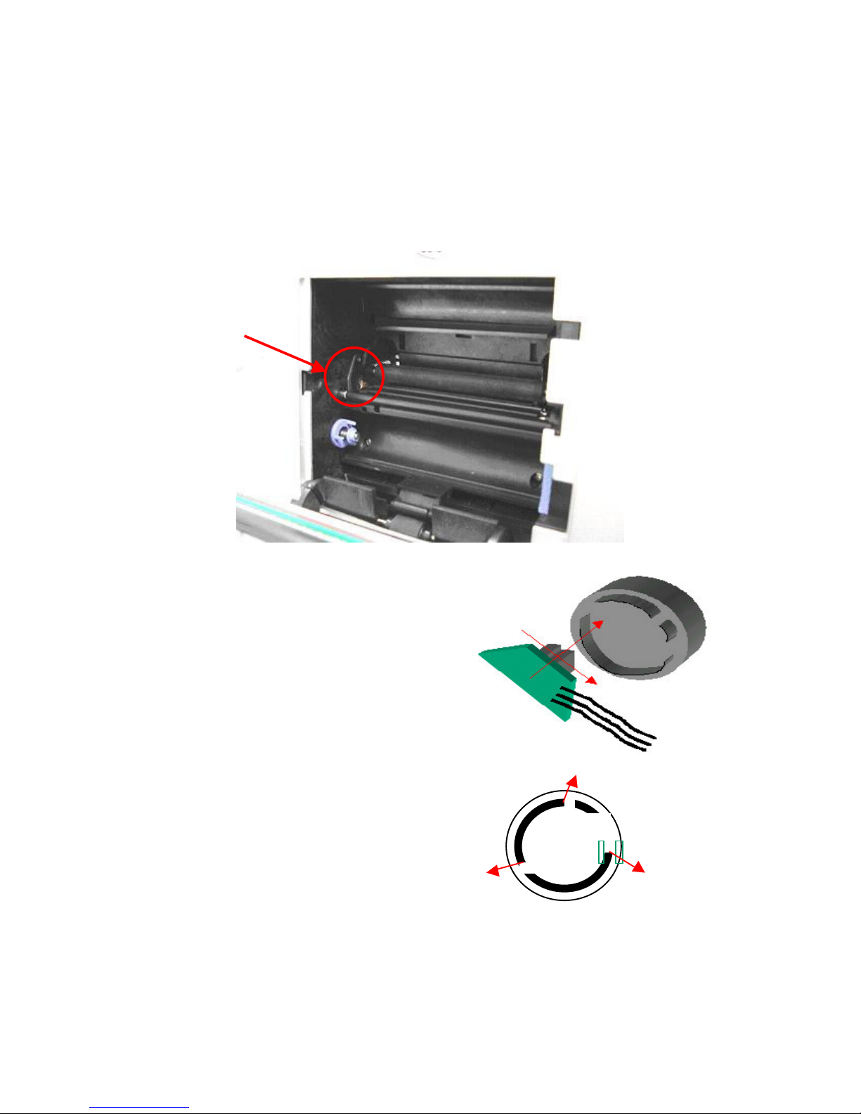
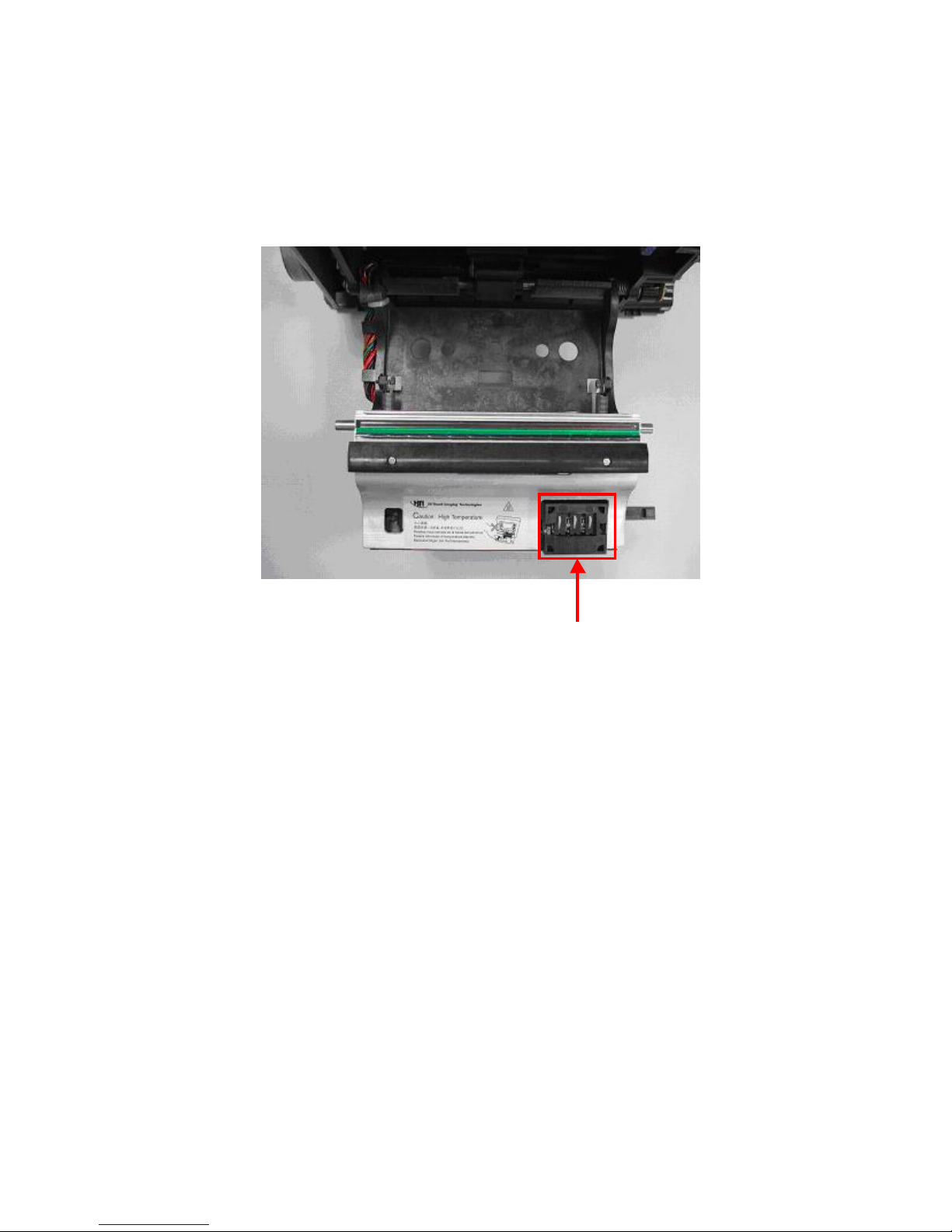
Ribbon Cassette (Door) Sensor
It is used to detect the status of the ribbon cassette and the ribbon door. The ribbon
cassette sensor will be on if the ribbon cassette type is correct; the Ribbon Cassette
Sensor will be off if the ribbon cassette type is wrong.
Ribbon Cassette sensor
Confidential
18
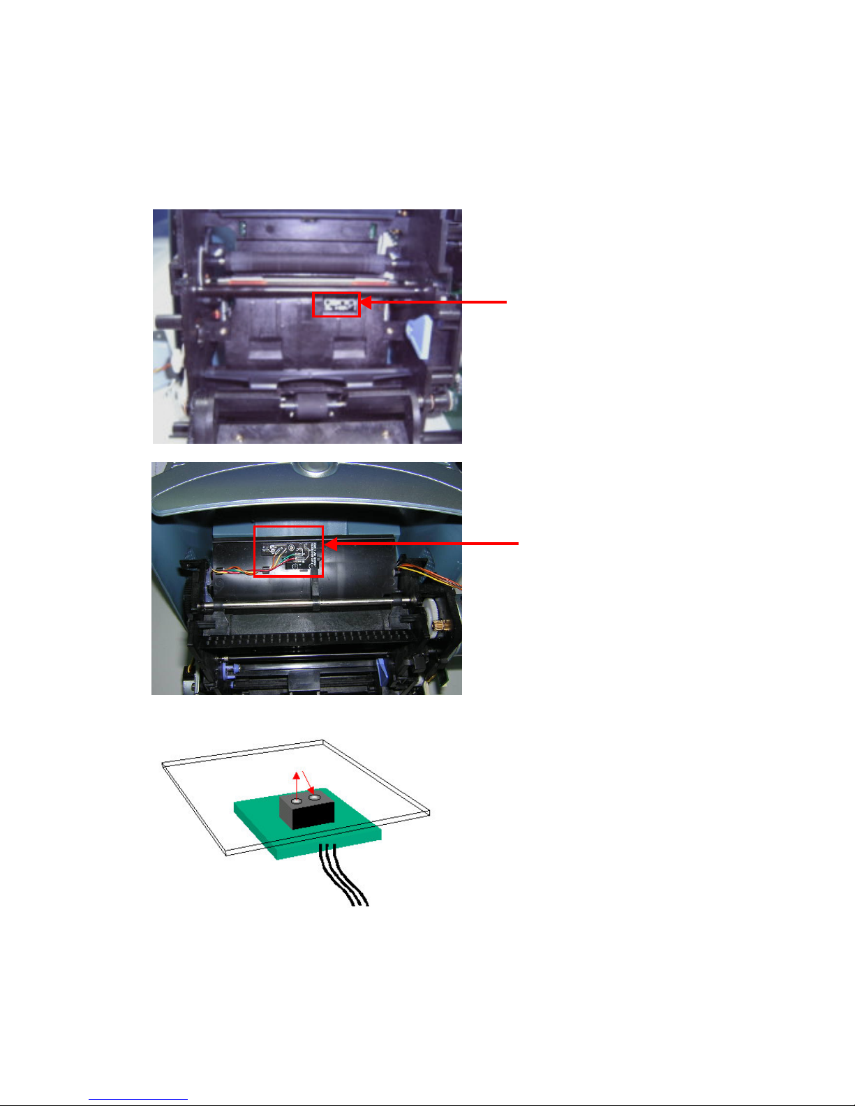
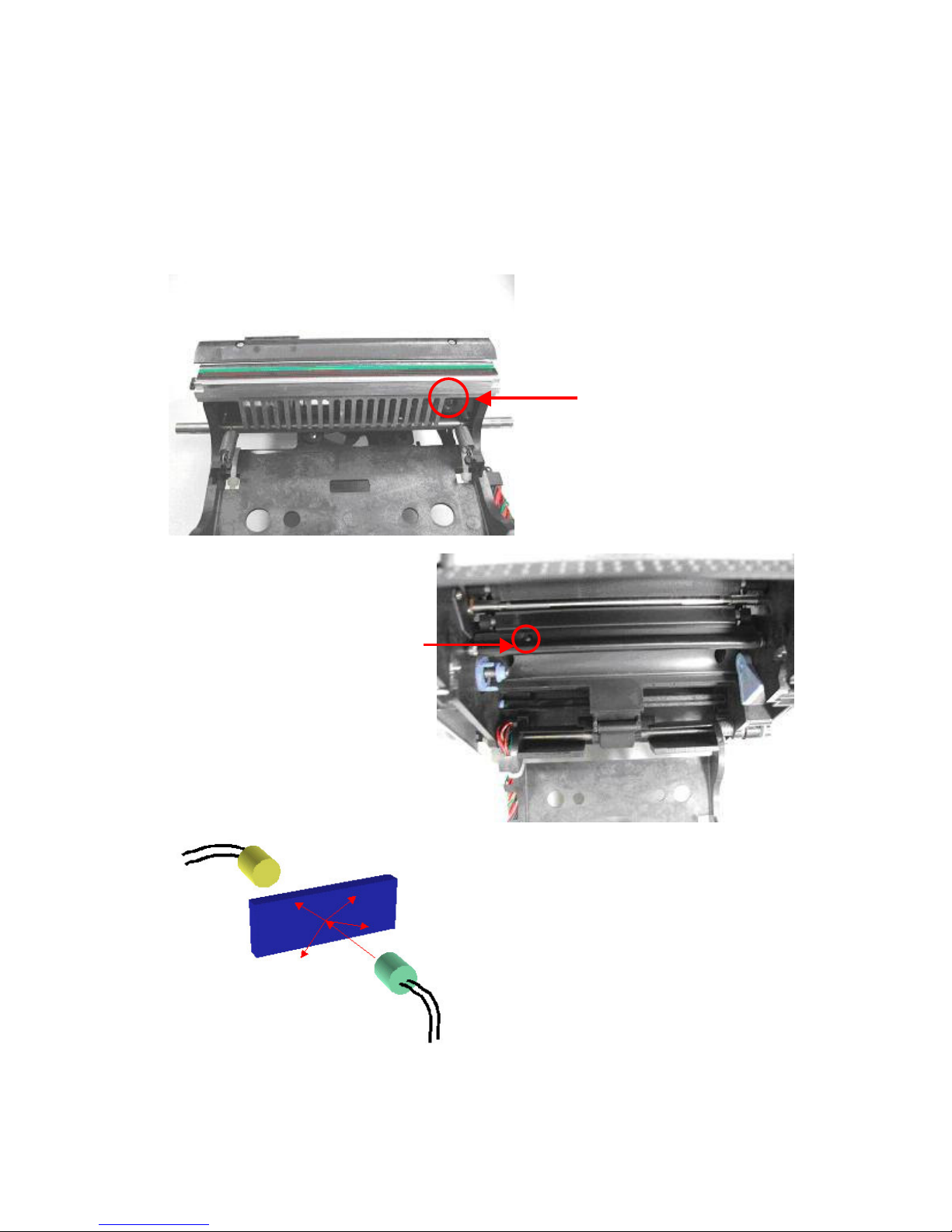
Ribbon LED/ Ribbon Sensor
The Ribbon LED and Ribbon Sensor is used to detect the ribbon status, it enables the
printer to detect the correct ribbon color. At the yellow or overcoat layer, the ribbon sensor
detects a HIGH value. In the magenta and cyan layer, the ribbon sensor detects a LOW
value.
Ribbon LED
Ribbon sensor
Confidential
19
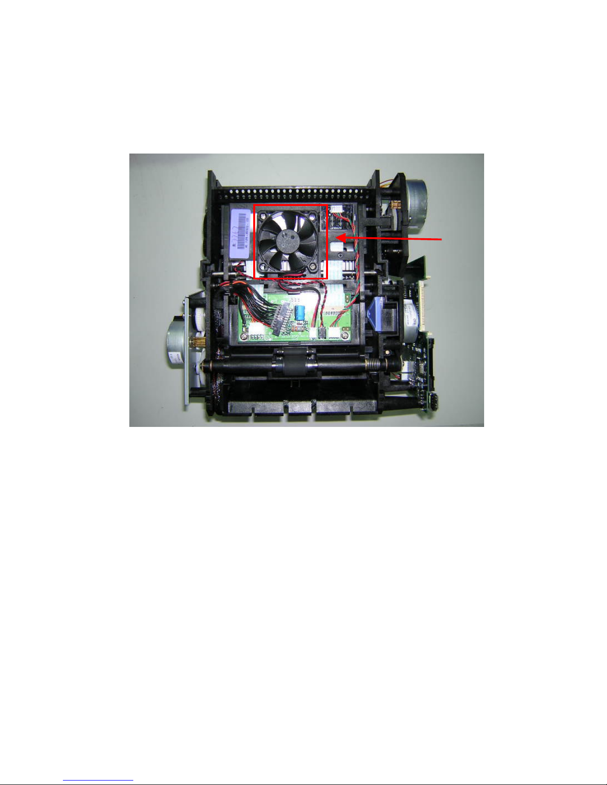
Fan
The Fan reduces the temperature of the TPH (Thermal Print Head). The fan only starts to
operate as soon as the temperature reaches a certain degree.
Fan
Confidential
20
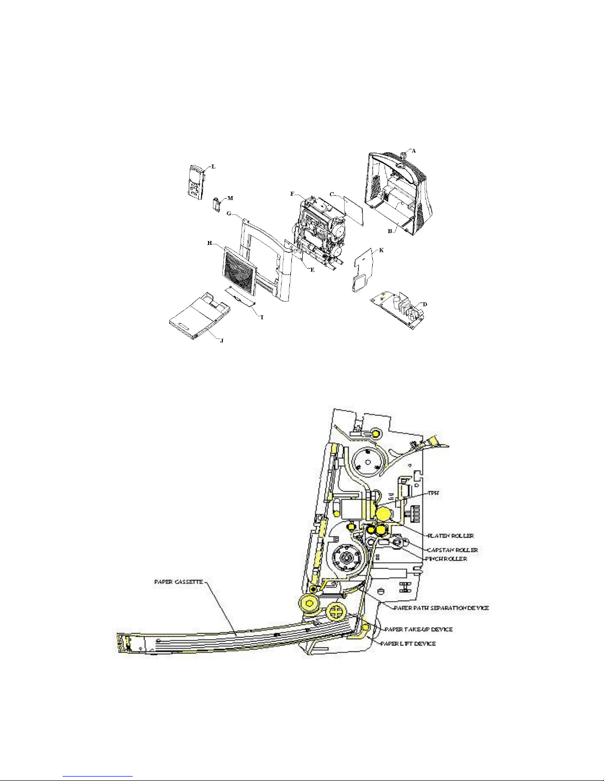
Mechanism
Basic Anatomy
A: Eject button B: Case back C: Main board
D: Bracket and power-board E: TPH board F: Chassis
G: Case front H: Ribbon door I: Paper door J: Paper cassette
K: Card board L: Controller M: Controller holder
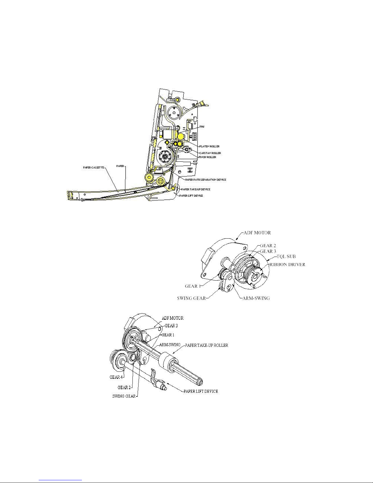
Transmission
The Auto Document Feed (ADF)/ Ribbon search device
Confidential
21
1. When the ADF Motor rotates the paper lifter gearing chain, the Paper Lifter device
starts lifting the elevator plate in the paper cassette up. The paper which lies at the top
position will then be in contact with the paper take up roller.
2. Now the photo p aper is
in contact with the
paper take up roller.
The pap er take-up roller
will grab the top paper
and lead the paper into
the p re-set p aper path.
3. The paper now passes
the leading edge (LE)
sensor. The p aper will
then be grabb ed by the capstan and pinch rollers. From this point onwards, the
paper’s movement is controlled by the capstan and pinch rollers.
4. While the capstan roller
controls the paper, the ADF
releases the paper lift device,
switches to operate the ribbon
gear chain and winds the
ribbon to the prop er frame.
Confidential
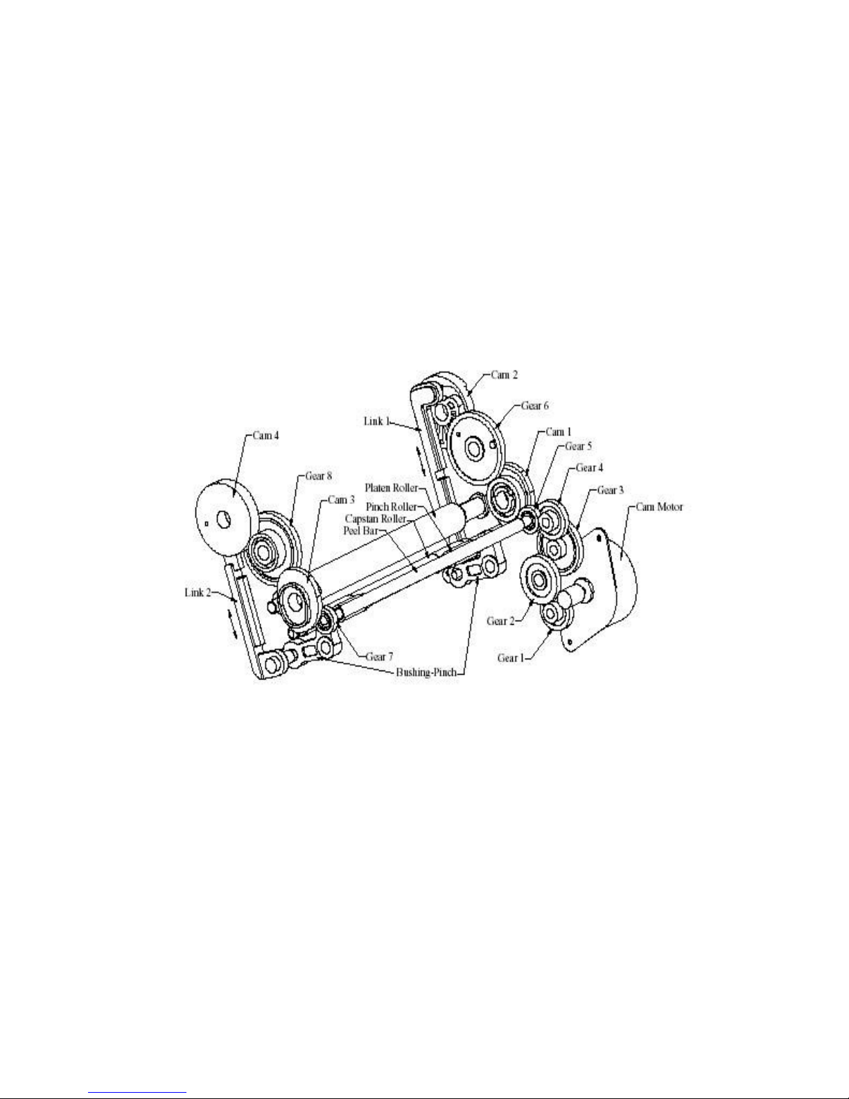
22
Cam position:
i. When the Cam M otor rotates, it will continue to operate Gear 1, Gear 2, Gear 3,
Gear 4, and Gear 5 in sequence.
ii. It will transfer power to another side of the Peel Bar after it receives p ower by
Gear 5. Both gear sides will then rotate synchronously.
iii. The process of the power transmission will go to Gear 5, Gear 7 Cam 1, Cam 3
Gear 6, Gear 8 Cam 2 and Cam 4.
iv. The internal cam design of Cam 2 and Cam 4, Link 1 and Link 2 can move in
and move out to operate the rotation of the Bushing-Pinch, and then separate
the Pinch Roller and the Capstan Roller.
Confidential
23
Firmware
Firmware update:
As the firmware is stored in the IC of the main board, you need to use the easy to use
BurnFW.exe application in order to update the printer’s firmware. Firmware updates can
easily be downloaded from the HiTi support website:
Go to www.hi-ti.com, then find the ‘Support’ se ction.
Firmware updates are always recommended and help to increase the printer’s lifetime and
efficiency.
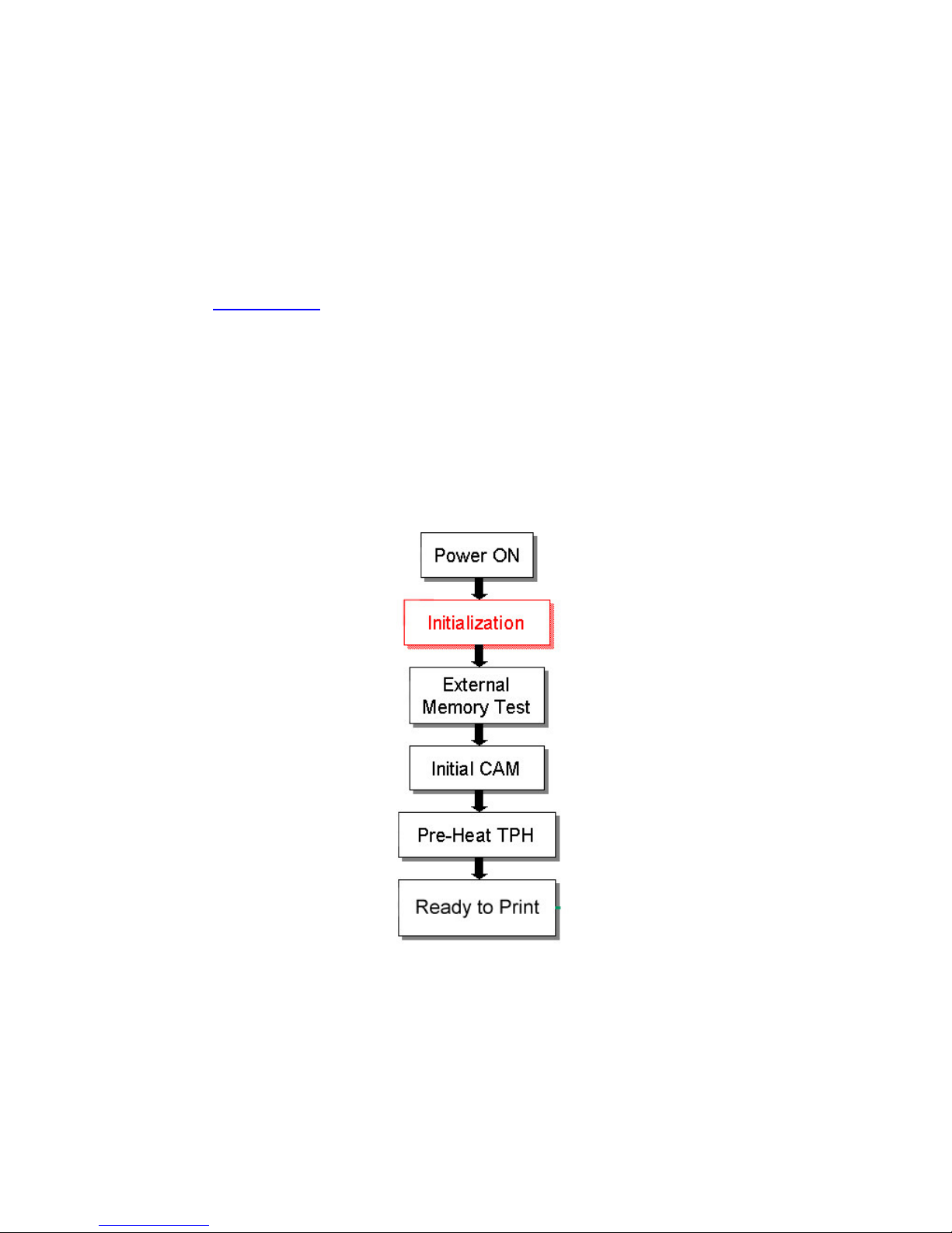
Initialization:
When the printer powers on, the initialization process will go through various stages.
(See below illustration). The status LED will keep blinking until the initialization process
has concluded.

Confidential
24
Host job flow:
After the printer is powered on, the firmware will control the printer’s operation.
Printing Step
Related Motor
Related Sensor
1 Check Ri bbon Cassette type Ribbon Cassette
2 Cam load to print position Cam Cam
3 Load pape r Capstan Jam
4 Ribbon registration (Y) ADF Ribbon
5 Print Yellow Capstan LE, Jam
6 Cam print to load position Cam Cam
7 Ribbon registration (M) ADF Ribbon
8 Back paper Capstan LE, Jam
9 Cam load to print position Cam Cam
10 Pri nt Magenta Capstan LE, Jam
11 Cam print to load position Cam Cam
12 Ribbon re gistration (C) ADF Ribbon
13 Back paper Capstan LE, Jam
14 Cam load to print position Cam Cam
15 Pri nt Cyan Capstan LE, Jam
16 Cam print to l oad position Cam Cam
17 Ribbon re gistration (O) ADF Ribbon
18 Back paper Capstan LE, Jam
19 Cam load to print position Cam Cam
20 Pri nt O vercoat Capstan LE, Jam
21 Eject paper Capstan
22 Cam print to i ni t position Cam Cam
Confidential
25
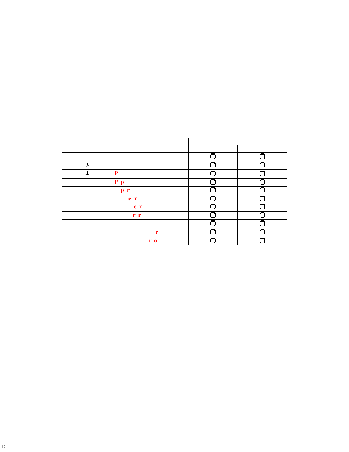
Error messages:
The firmware controlled Status LED shows the error status:
Green Signal Li ght:
Stable : Printer is ready for processing job
Blinking slowly: Printer is processing job or initializing after power on
Blinking fast: Printer is writing firmware
IMPORTAN T: N EVER TURN THE PRINTER OFF WHILE ANY LIGHT I S
BLINKING OR WHILE YOU CAN STILL HEAR OPERATIONAL SOUNDS FROM
THE PRINTER
Orange Signal Light:
Model LED blinking
ti mes
Error description
640PS 641PS
1 Cove r open
3 Ribbon out
4 Paper out
5 Paper jam
6 Paper mismatch
8 Cam error
9 Nvram error
11 Asi c error
12 Adc e rror
13 Fw checksum error
16 Write flash error

Confidential
26
Chapter 3: Disassembly
Safety Instructions for all HiTi products: Printers
• Read these instructions carefully. Save these instructions for future reference.
• Follow all warnings and instructions marked on the printer.
• Unplug the printer from the wall outlet before disassembly.
• Do not place the printer on an unstable cart, stand, or table. The printer may get
damaged by a fall.
• Openings in the chassis and the bottom are provided for ventilation purposes and
to ensure reliable operation of the printer by protecting it form overheating: these
openings must not be blocked or covered.
• Placing the printer on a bed, sofa, rug, or other similar, not firm surfaces may
block the openings. The printer should never be placed near or over a radiator or
heat register, proper ventilation and coolin g must be provided at all times.
• The printer should only be operated with the type of power indicated on the
marking label. If you are not sure of the type of power available in your area,
consult your dealer or local power comp any.
• If an extension cord is used with this product, make sure that the total ampere
rating of the equipment plugged into the extension cord does not exceed the
extension cord ampere rating. Also, make sure that the total rating of all products
plugged into the wall outlet does not exceed the fuse rating.
Confidential
27
Tools
Tweezers
Screwdriver – minus
Confidential
28
Screwdriver – plus
IC Clamp
Confidential
29
Wire Cutter
Confidential
30
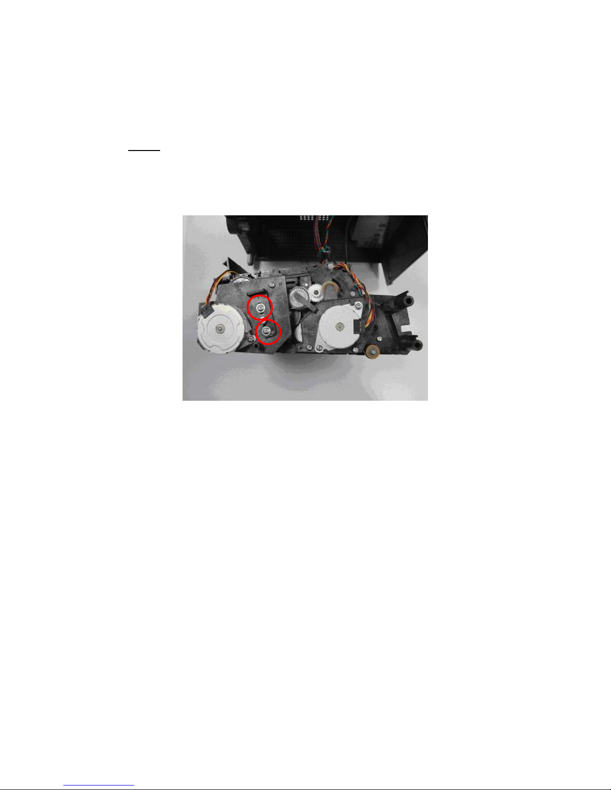
Do not disassemble these Parts:
HiTi stri ctly prohibits anyone to disassemble the TPH (Thermal Print Head) and
the Bracket-idle . Both parts need to be cal ibrated by a spe cific calibration device
and cannot be repaired on site:
Bracket-idle:
 Loading...