

HiTi Digital 630PS Service Manual

Ver. Ex.1.1 Confidential 2003/7/8
630PS
Service Guide

Ver. Ex.1.1 Confidential 2003/7/8
Copyright
The information contained in this document is subject to change without notice.
Hi-Touch Imaging Technologies makes no warranty of any kind with regard to
this material, including, but not limited to, the implied warranties of
merchantability and fitness for a particular purpose.
Hi-Touch Imaging Technologies shall not be liable for any errors or for
incidental or consequential damages in connection with the furnishing,
performance, or usage of this material.
Reproduction, adaptation, or translation of this manual is prohibited without
prior written permission of Hi-Touch Imaging Technologies, except as allowed
under the copyright laws.
Hi-Touch Imaging Technologies, HiTi, HiTi corporation logo, PhotoDesiree,
"Digital mini-lab just for you" and HiTi name (written in Simplified Chinese or
Traditional Chinese) are trademarks or registered trademarks in Taiwan, China
and other countries of Hi-Touch Imaging Technologies.
Disclamer
This document is suitable to field site engineers, but not end-user. Field site
engineers should read both “Service Guide” and “User’s Manual” to service
end-user. Any comments or suggests, please email csd@hi-ti.com
.

Ver. Ex.1.1 Confidential 2003/7/8
Chapter 1. Overview
“HiTi Photo Printer 630PS” is aimed at the most cost effective standalone
photo finish machine for digital camera and photography. With a supreme
specification and cost effective design structure, 630PS will surely provide a
real photo quality output solution and one-touch photo finish machine for users
to print with fun and ease.
“HiTi Photo Printer 630PS” is a popular printer with high-speed, high-quality
and compact size. This printer is focused on printing “photos”, including of the
application on photo (4”x 6”), ID photo (1” or 2”), business card, greeting card
and more.
“HiTi Photo Printer 630PS” is a standalone printer. You don’t need to
communicate with host PC for printing. You can print instantly whenever you
want. “HiTi USB Photo Printer 630PS” also supports USB interface to
communicate with host PC, which meets the standard of USB 1.1 version. It’s
compatible with USB 2.0 host device. Any win32-based photo printing
application such as “HiTi PhotoDesiree”, “Adobe PhotoShop”, “Jasc Paint
Shop Pro” and “Newsoft Mr. Photo”, or vectors based applications such as
“Corel Draw!” are applicable in this printer.
“HiTi Photo Printer 630PS” includes of the following functions:
9 Printing Process
YMCO 4 passesΰYellow, Magenta, Cyan, and Over-coatingα
Over coating ensures that HiTi’s printouts can be kept longer than
inkjet printer’s printouts.
9 High Quality Resolution
300x300 dpi
Equal to 4800x4800 dpi ΰcompare with inkjet system.α
9 Convenience
Dual memory card support. HiTi Photo Printer 630PS provides two
types of card slot to let user print instantly.

Ver. Ex.1.1 Confidential 2003/7/8
Stand-alone operation & PC link. Could preview what you want to
print instantly.
630PS can be your card reader(images only).
F/W code and template could be downloaded by USB.
Offer large data buffer (32MB SDRAM).
HiTi Photo Printer provides an application “PhotoDesiree”, designed
especially for printing 4”x6” photos, ID photos, calendars, photo
business cards, photo greeting cards and more.
Application “PhotoDesiree” extends more functions for photo printer.
It makes photo creation easily, and it is very handy to use!
Ver. Ex.1.1 Confidential 2003/7/8
Chapter 2. Specification
No Item Description
1 Model HiTi 630 PS
2 Printing Method Dye Diffusion Thermal Transfer (D2T2)
3 Color Continuous-tone output, 256-level each
color
4 Paper Feed Cassette type automatic feeder.
5 Resolution 300x300dpi
6 Pixel 1200x1800 pixels
7 Printing Size 4”x 6”
8 Paper Size 4”x 7” with detachable boundary
9 Paper Cassette Capacity 25 sheets
10 Ribbon Cassette Capacity 50 images YMCO
11 Interface USB 1.1
12 Card Socket CompactFlash card Type 2 x1
SmartMedia card x1
13 File Format Support EXIF, JPEG, DPOF
14 Power Supply 100~240V, 50/60 Hz,75W
15 Printer Dimension 218(W) x 210(H) x 140(L) mm
16 Controller Dimension 60(W) x 23(H) x 130(L) mm
17 LCD Size 1.6” TFT LCD
18 Image Dimension in LCD TBD (small footprint)
19 Weight 2.0 kg
20 OS Windows 98/ME/2000
21 Minimum System
Requirement
Win 98/MEΚ64MB RAM, Pentium PC
Win 2000Κ128MB RAM, Pentium PC
22 Package kit Power Cord, USB Cable, CD (630 PS
Driver, PhotoDesiree, Acrobat Reader
5.0, Mr. Photo 3.1 and Manual), 10
images YMCO Ribbon, 8 images photo
paper, 1 image 4 x 4 sticker, 1 image
composite (4/2/4) sticker
23 Options 50 images YMCO Ribbon, 50 images
photo kit, 50 images 4 x 4 sticker kit, 50
images composite (4/2/4) sticker kit, 25
images photo and 25 images 4x4 sticker
kit, 25 images photo and 25 images 4/2/4
sticker kit, 25 images 4x4 sticker and 25
images 4/2/4 sticker kit

Ver. Ex.1.1 Confidential 2003/7/8
Chapter 3. Hardware
630PS Circuit Theory
The circuit of 630PS contains five parts: main board, power board, card board,
controller board, wires & cables. Functionally, power board is an AC to DC
power conversion device, and it provides a 75W, 18V, DC source to drive the
630PS photo printer. Main board adopts 18VDC from power board to drive
motor driver ICs and fan, and also transforms the input 18V to 5V and 3.3V by
voltage regulators for ASIC, Memory, Video IC, and the I/Os. Card board,
which adopts 3.3V DC from main board, provides an interface for main board
to control CompactFlash and SmartMedia memory card, it is connected with
main board by a 3 pins power wire and a 50 pins signal cable. Controller board,
which consists of a 1.6-inch TFT-LCD panel, the user buttons, and the control
circuit, is to be the user interface (UI). The 18V DC from power board and the
video signals from main board are connected to controller board. Besides, The
TFT-LCD panel on controller board is to display images and messages for user
operations.
Ver. Ex.1.1 Confidential 2003/7/8
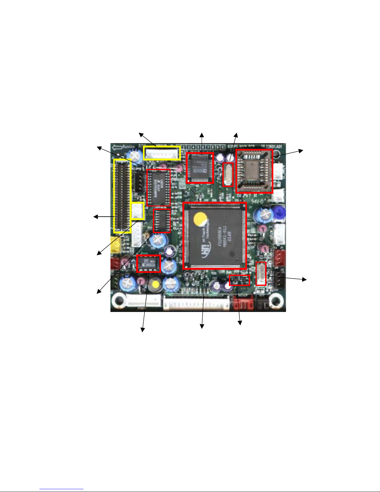
3.1 Main Board
The circuit theory of main board will be divided into seven parts.
Fig 2. Main Board
FlashRo
m
24MHz
Power low
d
etec
t
ASIC F2680EA
34063
Cam motor
Driver ULN2003
Card b/d
p
owe
r
Card b/d interface
Capstan Motor
Driver 6219
Controller
AD7171 27MHz
Ver. Ex.1.1 Confidential 2003/7/8
Fig 4. Main Board
3.1.1 ASIC Architecture
The most important IC on the main board is FD2680E, which is designed by
HITI. This ASIC contains a DSP core, a 8032 MCU, a SDRAM controller, a
CCIR601/656 Video controller, a CompactFlash card controller, a SmartMedia
card controller, a multi-type thermal print engine, an USB controller, the
embedded SRAM, an ADC, and IOs. Firmware can control the action of printer
via the versatile interfaces of FD2680E ASIC.
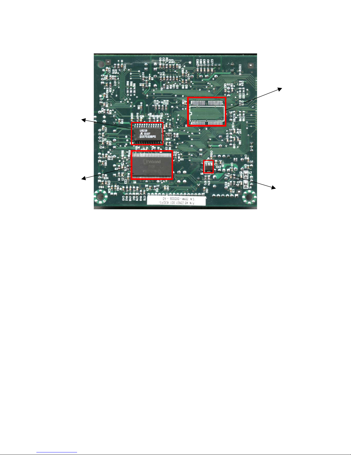
3.1.2 Memory IC
a) SDRAM
This 256Mbit SDRAM on main board is to be the data buffer. The image
file, print data, video frame are temporarily stored during operation.
N
AND flash
3.3V
256Mb
ADF motor
Driver
Ver. Ex.1.1 Confidential 2003/7/8
b) NOR Flash
This 4Mbit flash memory is to stored the MCU code, the DSP code, the
logo, the OSD (On-Screen Display) map and etc.
c) NAND Flash
This 64Mbit NAND flash memory is to stored the template for image
processing.
3.1.3 Video Encoder
This chip is used to convert the CCIR601/656 digital interface signals to
NTSC/PAL video signals.
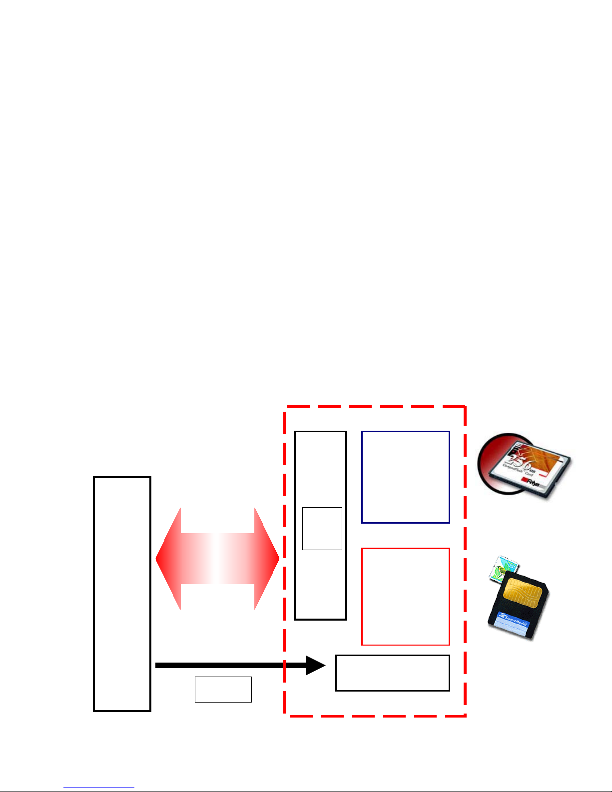
3.1.4 Memory Card Interface
To control the CF and SM memory cards which are inserted on card board via
cable.
PCMCIA
CF/SM
Interface
Main
B/D
CF socket
50 pin
SM socke
t
22 pin
Power switch
3.3 Volt
50 pin
header
Ver. Ex.1.1 Confidential 2003/7/8
3.1.5 LED & Sensor
3.1.5.1 Status/Error LED
Show printer status and error message. Green shining LED means printer is
ready. Green blinking LED means printer is busy. Orange blinking LED means
error message. (See “Chapter 7. Troubleshooting” for more information about
error message.)
Fig 6. Status/Error Sensor
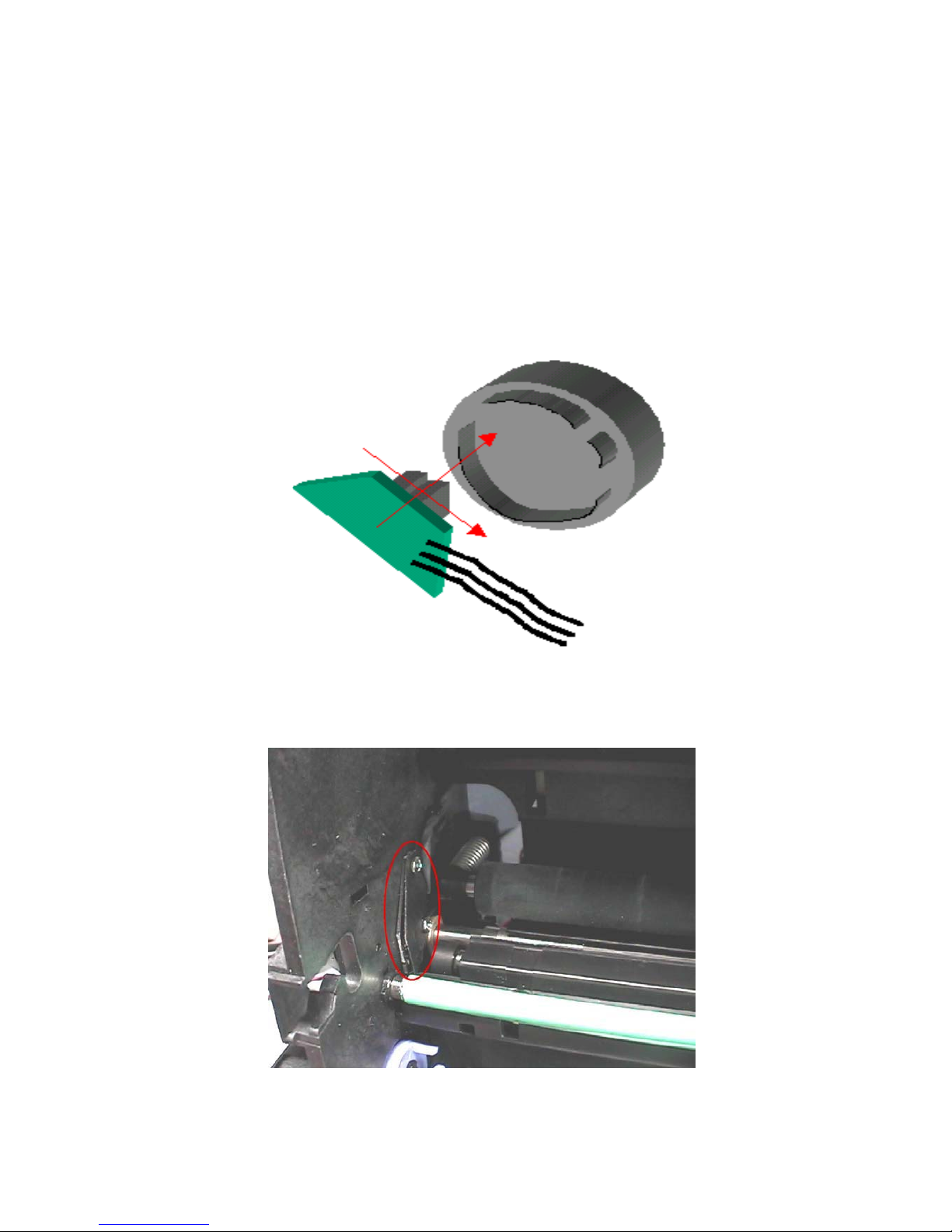
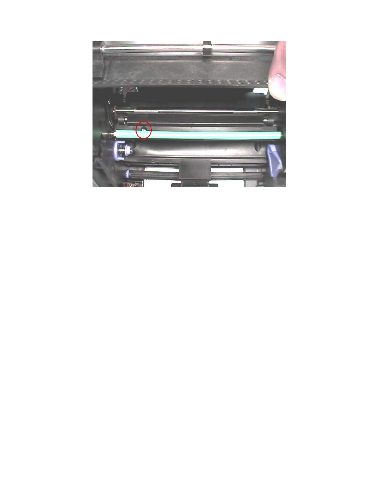
3.1.5.2 CAM Sensor
Under different status, the position of platen roller is different. Cam sensor
indicates the position of platen roller and pinch roller. It has three positions, P1:
initial position, P2: load position, and P3: print position. The CAM controls the
platen roller moving between these positions, and the CAM sensor detects &
feedback the position information to firmware.
P1 = Initial Position
At this position, the gap between platen roller & TPH is largest. While
printer power on or reset, it will be at this position. The large gap
between platen roller & TPH enable paper moving through the gap.
At this position, the pinch roller is releasing as well.
Ver. Ex.1.1 Confidential 2003/7/8
P2 = Load Position
At this position, the gap between platen roller & TPH is not as large as
P1. But still has gap to enable ribbon scrolling through the gap. The
pinch roller touches capstan roller to enable paper loading.
P3 = Print Position
Platen roller close to TPH, paper unmovable. No gap between platen
roller & TPH.
Fig 7. Cam Sensor Drawing
Fig 8. Cam Sensor
Ver. Ex.1.1 Confidential 2003/7/8
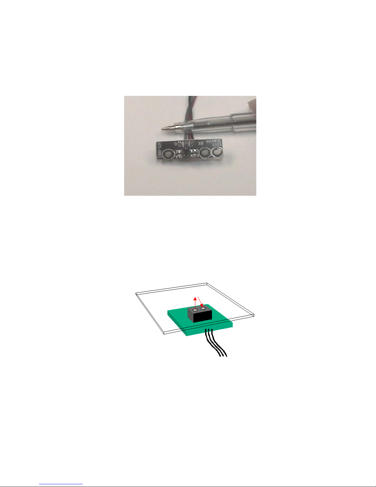
3.1.5.3 Leading Edge Sensor
It’s used to detect the status of paper. Leading Edge will be on when it detects
paper loading; Leading Edge will be off when it doesn’t detect paper loading.
Fig 9. Leading Edge Sensor
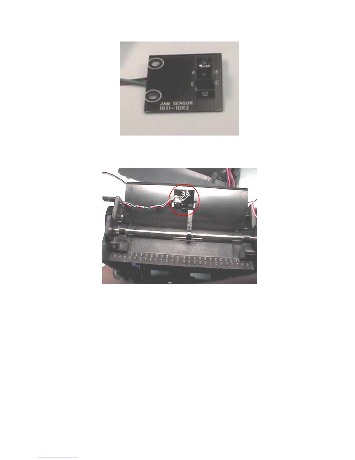
3.1.5.4 Jam Sensor
It’s used to detect the status of paper. Jam Sensor will be on when it detects
paper passing; Jam Sensor will be off when it detects paper jam.
Fig 10. Jam Sensor
Ver. Ex.1.1 Confidential 2003/7/8
Fig 11. Jam Sensor
Fig 12. Jam Sensor
3.1.5.5 Ribbon Cassette Sensor
It’s used to detect the type of ribbon cassette and the status of ribbon door.
Ribbon Cassette Sensor will be on if the type of ribbon cassette is correct;
Ribbon Cassette Sensor will be off if the type of ribbon cassette is wrong. In
addition, Ribbon Cassette Sensor will be on if it detects ribbon door is closed;
Ribbon Cassette Sensor will be off if it detects ribbon door is open.
Ver. Ex.1.1 Confidential 2003/7/8
Fig 13. Ribbon Cassette Sensor (Front View)
Fig 14. Ribbon Cassette Sensor (Back View)
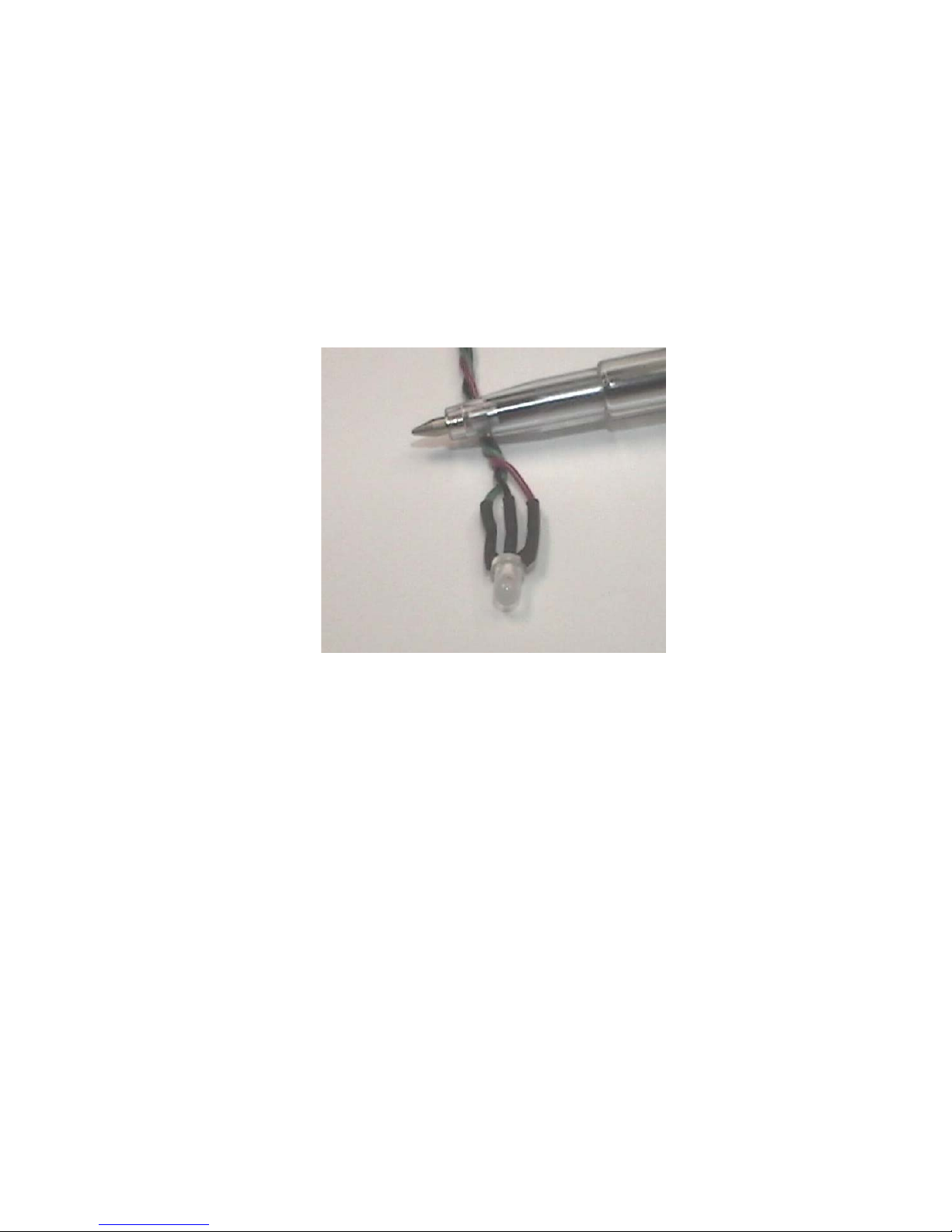
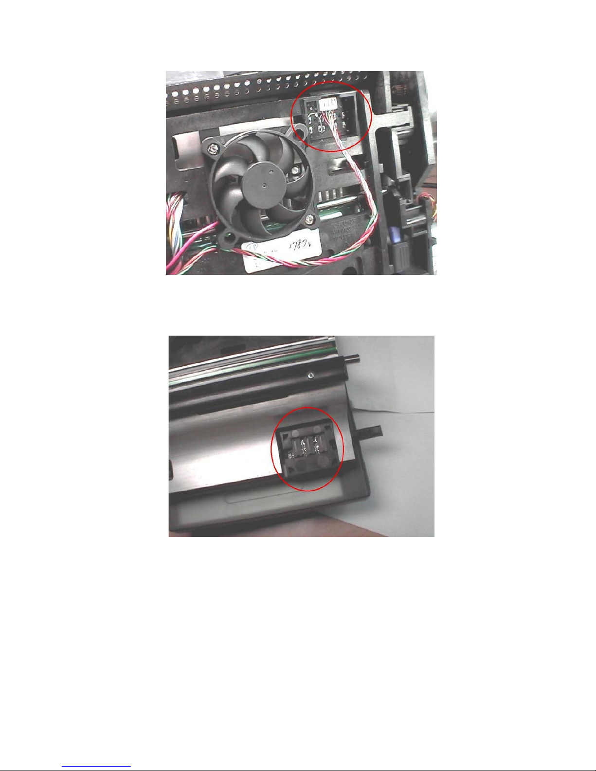
3.1.5.6 Ribbon LED/Ribbon Sensor
It’s used to detect the ribbon status, enable printer to control the ribbon scrolling
correct. Detect ribbon color. In yellow or overcoat layer, ribbon sensor senses
HIGH. In magenta and cyan layer, ribbon sensor senses LOW.
Ver. Ex.1.1 Confidential 2003/7/8
Fig 15. Ribbon LED/Sensor
Fig 16. Ribbon LED
Ver. Ex.1.1 Confidential 2003/7/8
Fig 17. Ribbon Sensor
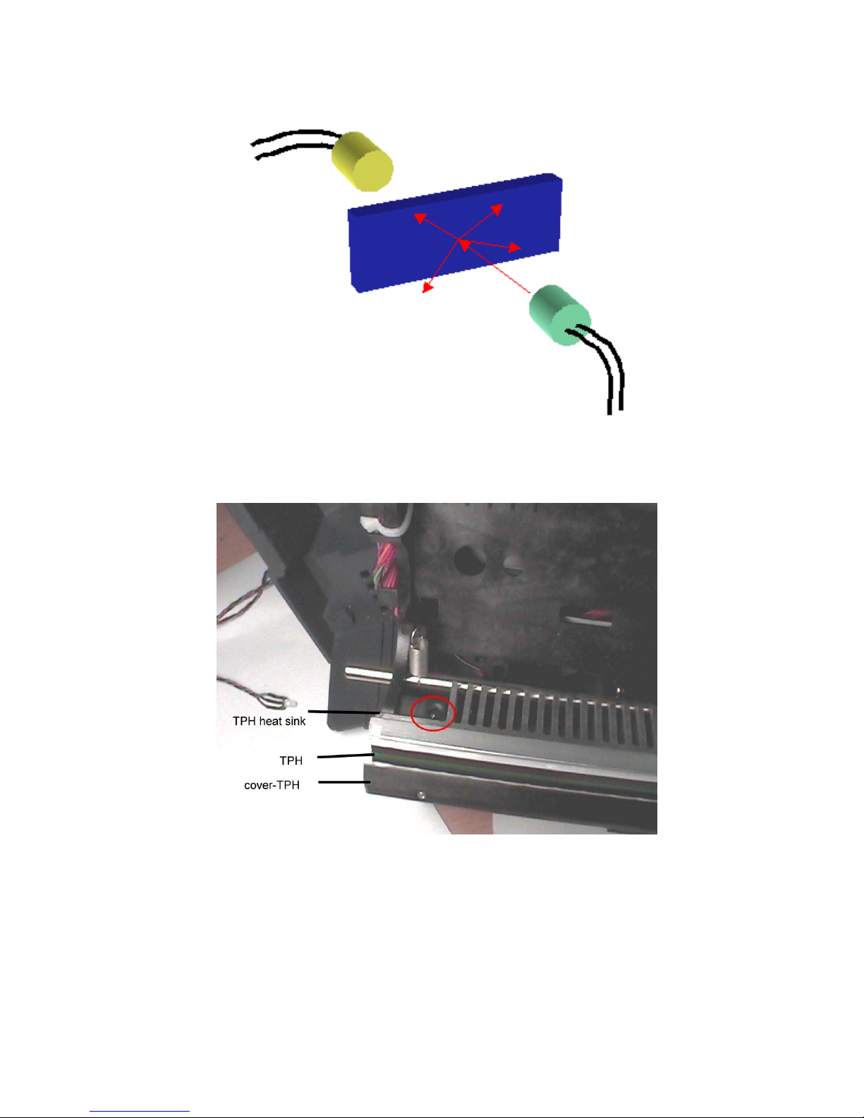
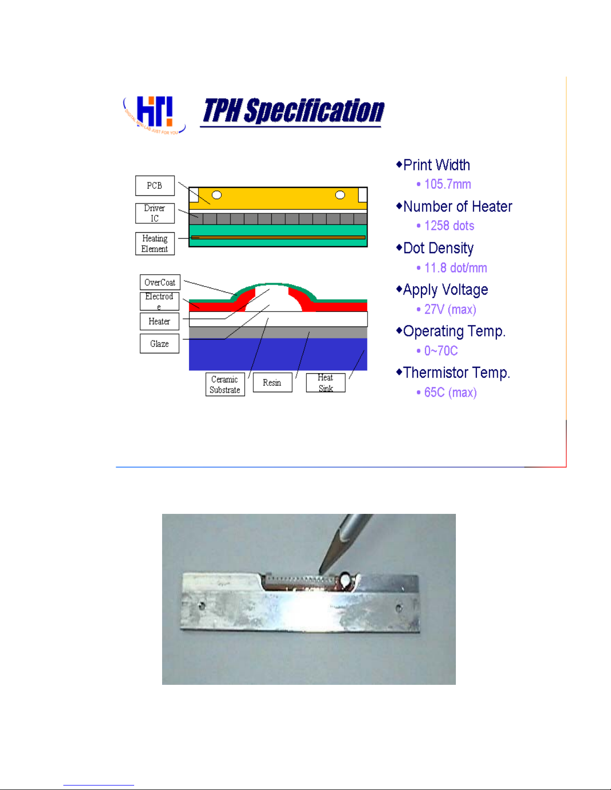
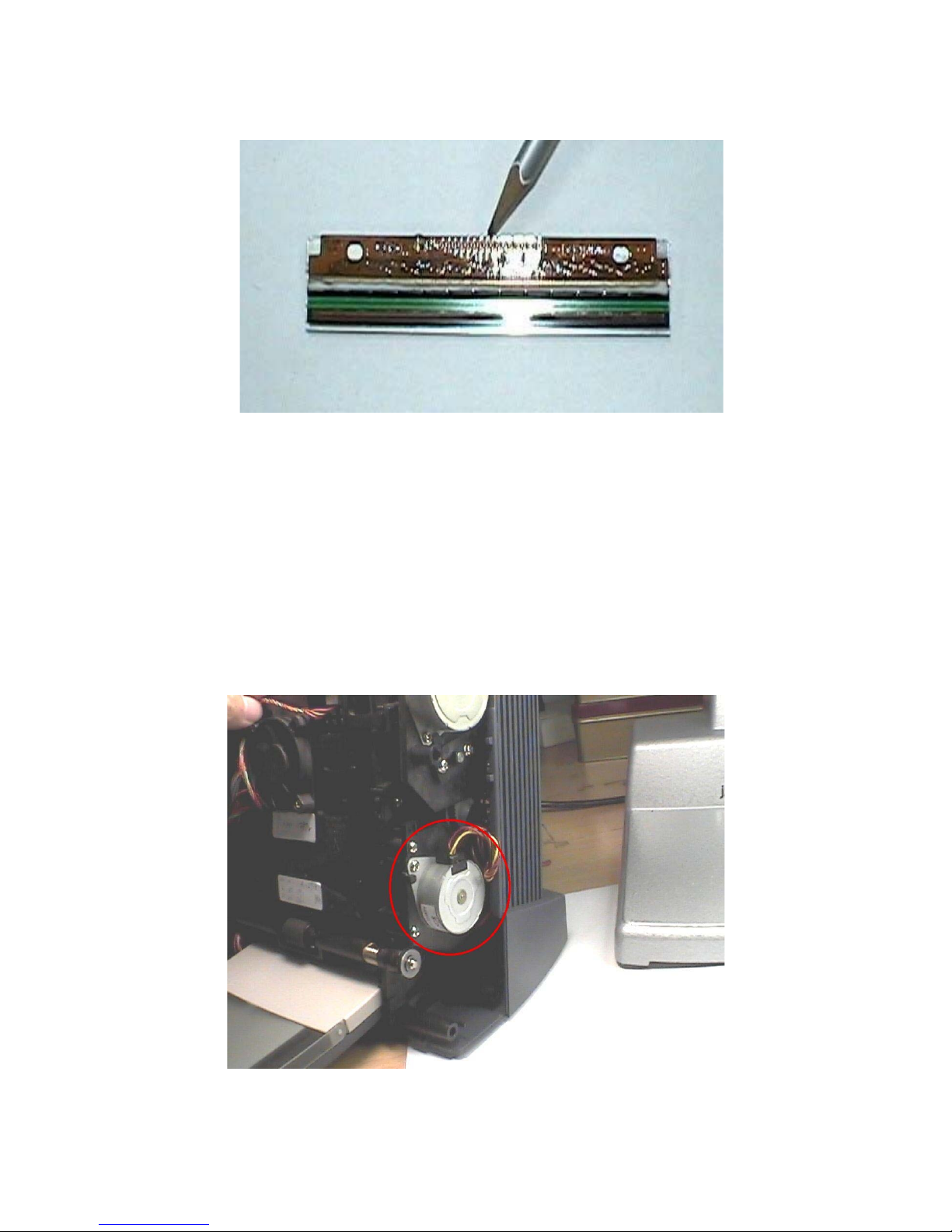
3.1.6 TPH
3.1.6.1 Specification
TPH(Thermal Print Head) is the key component for D2T2 printer, like the inkjet
printing head for inkjet printer. Print data will be shifted into TPH during each
clock. After 384 shift clocks, one line data will be shifted to TPH. Latch/ signal
will latch the print data. Strobe/ signal will heat the corresponding heater
elements on TPH according to shift-in data. More the strobe/ time, more the
dye of the ribbon transfers to paper.
Ver. Ex.1.1 Confidential 2003/7/8
Fig 18. TPH Specification
Fig 19. TPH (Back View)
Ver. Ex.1.1 Confidential 2003/7/8
Fig 20. TPH (Front View)
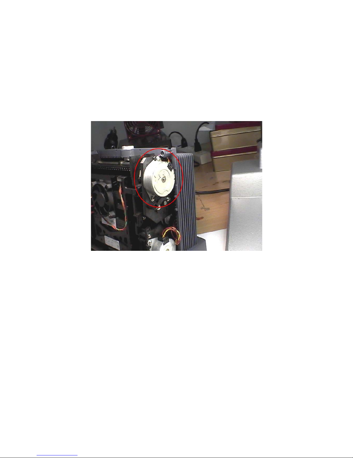
3.1.7 Motor
3.1.7.1 Cam motor
Cam motor is a unipolar motor. It’s driven by driver IC “ULN2003”. ULN2003
has high voltage and high current Darlington arrays. Therefore, it can support
continuous load of current rating to 500 mA.
Fig 21. Cam motor
Ver. Ex.1.1 Confidential 2003/7/8
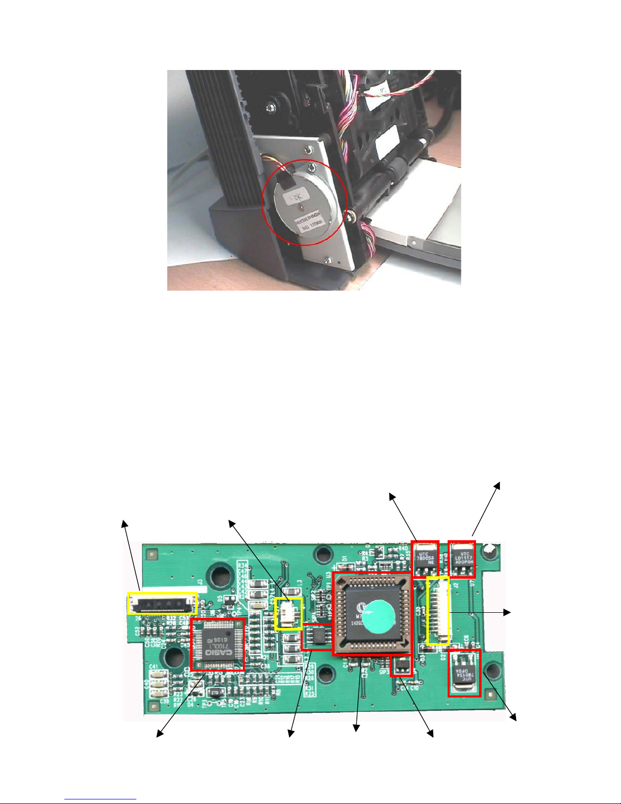
3.1.7.2 Capstan motor
Capstan motor is a bipolar motor. It’s driven by driver IC “L6219”. L6219 is
designed to operate both windings of bipolar stepping motor. It supports
Pulse-Width-Modulation (PWM) control of output current to 750 mA. For PWM
control, the maximum output current is determined by user’s selection of a
reference voltage and sensing resister.
Fig 22. Capstan Motor
3.1.7.3 Ribbon/ADF motor
Ribbon/ADF motor is a bipolar motor. It’s driven by driver IC “A3966”. A3966 is
designed to operate both windings of bipolar stepping motor. It supports
Pulse-Width-Modulation (PWM) control of output current to 650 mA. For PWM
control, the maximum output current is determined by user’s selection of a
reference voltage and sensing register.
Ver. Ex.1.1 Confidential 2003/7/8
Fig 23. Ribbon/ADF Motor
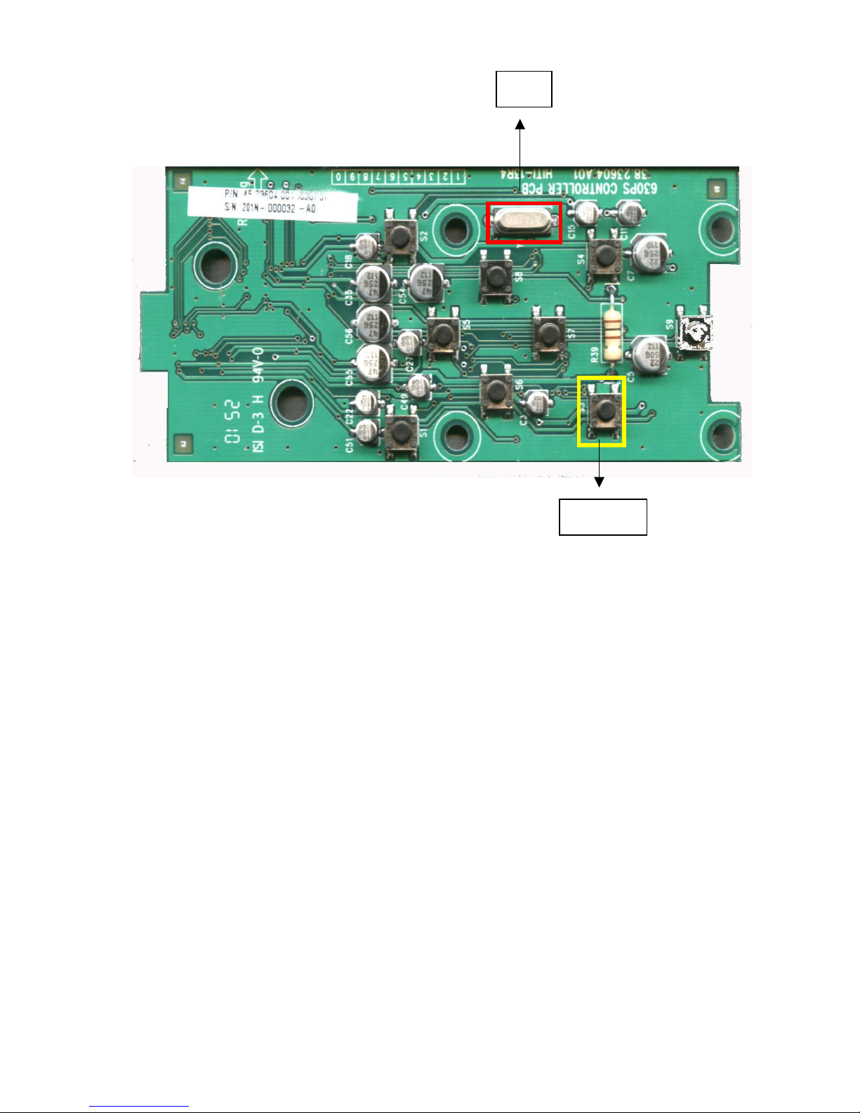
3.2 Controller Board
The circuit theory of controller board can be divided into four parts.
a) Power Circuit
b) CPU and serial EPROM
c) LCD driver
d) LCD and backlight LED
LCD control CHIP
Serial EEPROM
24C02
78E51 3.3V regulator
LED fixed
Curren
t
Control
Controller I/F
78D15
78D05
LCD’s back light control
LCD I/F
Ver. Ex.1.1 Confidential 2003/7/8
3.2.1 Power circuit
The input power of controller board is 18V. The power circuit uses voltage
regulators to provide15V, 5V and 3.3V for other components. The 13.5V is got
from 15V after the voltage drop of two diodes – 1N4148 . The LED backlight
require a 13.6V--19mA power source. Constant current will keep constant
lightness. The adjustable regulator – LD1117 can fulfil this requirement and
another NPN transistor – 2N3904 are used to switch ON/OFF the backlight.
3.2.2 CPU and serial EPROM
This controller board uses a 80-series CPU with 4KB on-chip FLASH EPROM
to do central control -- including initial setting of LCD driver IC, LED backlight
control, button-pushed sensing and communication with main board. The
serial EPROM stores setting data of LCD which is got from the calibration
process. CPU will read the serial EPROM and complete the initial setting for
LCD after power on.
24MH
Tact switch
Ver. Ex.1.1 Confidential 2003/7/8
3.2.3 LCD driver
The CM7100 is a video interface IC for TFT color LCD that accept RGB signal
inputs on a single chip. It supports a serial data control which can set image
quality adjust circuit.
3.2.4 LCD and backlight LED
The 1.6-inch TFT LCD panel is used to display images and messages. This
panel is driven by a specific LCD driver and its backlight is low DC voltage
white-LED.
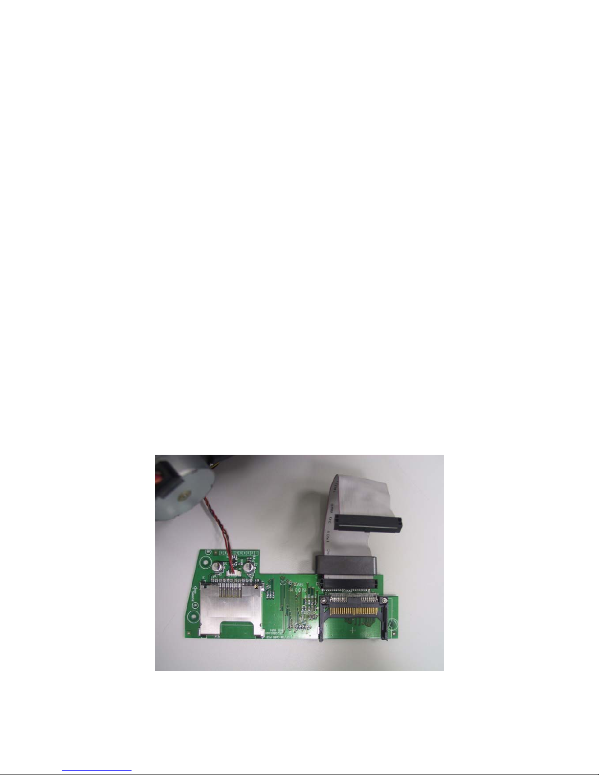
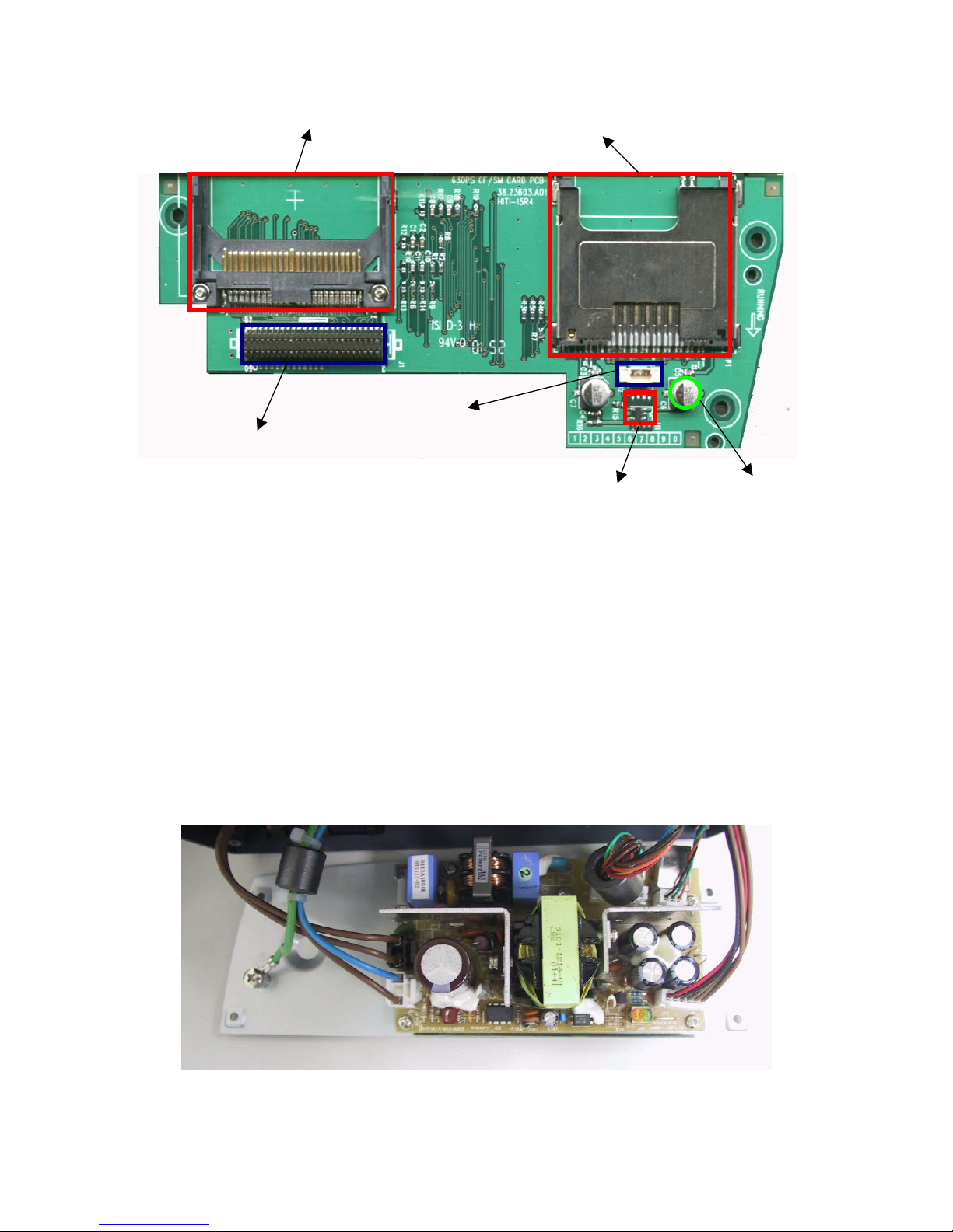
3.3 Card Board
The only one IC on card board is RT9701 -- a power switch. This switch is to
disable power supply of memory card sockets when no cards are inserted.
After either one of the sockets is inserted a CompactFlash card or a
SmartMedia card, the CD(card detection) is pulled low and the power switch
will be turned on by ASIC.
Fig 24. Card Board
Ver. Ex.1.1 Confidential 2003/7/8
3.4 Power Board
It contains the Transformer, Snubber Circuit, and Power MOS. The function of
Sunbber Circuit is reducing the transient Spike Voltage Power MOS produces
when MOS be turned off. It prevents the Power MOS to be destroyed by the
transient Spike Voltage. Transformer is the component which transforms
energy. It is also separateness of the primary and secondary. It can use
proportion of coils to change the voltage between primary and secondary. The
Power MOS is controlled with UC3842A to switch energy of Transformer so
that is able to regulate Output Voltage.
Fig 25 Power Board
Card b/d powe
r
Power control IC EL Cap.(SMD
)
Card b/d I/F
Ver. Ex.1.1 Confidential 2003/7/8
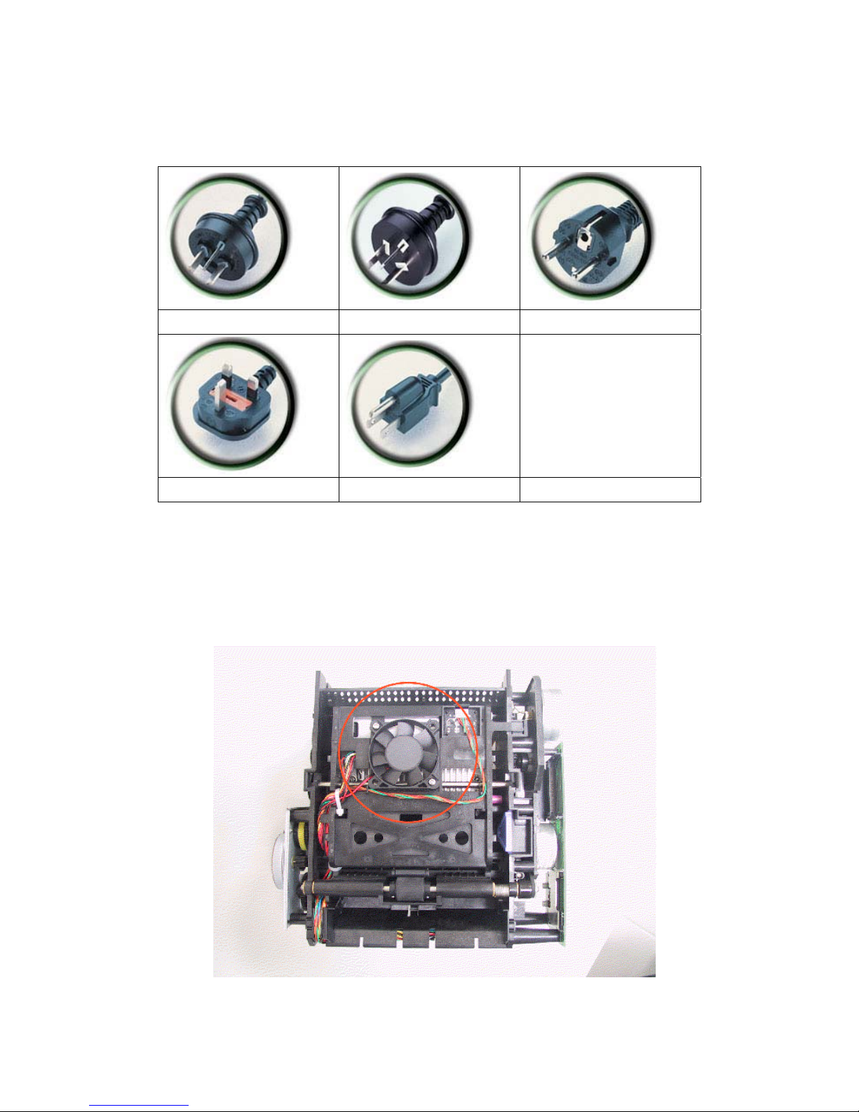
3.5 Power Cord
Australia China Europe
UK US
Fig 26 Power Cord
3.6 Fan
It’s used to reduce the temperature of the TPH (Thermal Print Head).
Fig 27. Fan
 Loading...