

Hitecsa VERNE WPHBA 171, VERNE WPHBA 251, VERNE WPHBA 201, VERNE WPHA Series, VERNE WPHBA 351 Series Manual
...
INSTALLATION, OPERATION & MAINTENANCE MANUAL
IOM_WPHBA-WPHA_091a1201_207954_180610_EN
WPHBA │ WPHA
Heat pump Cooling only
PACKAGED HORIZONTAL WATER-TO-AIR CONDITIONERS
Models: 091│121│141│171│201│251│351│401│501│701│751│1001│1201
Cooling Capacities: from 2.4 to 41.0 kW
Heating Capacities: from 2.8 to 46.4 kW

Thank you for trusting the Hitecsa Products. Our company has been offering the market an extended range of specialized units for
air conditioning and cooling installations for over 35 years. Our approach is based on efficiency, adaptability, usability and practical
solutions. This has been the hallmark of our product catalogue.
The versatility of our factory allows us to contribute solutions, almost tailored to each project’s specifications, in search of a solution
to every problem that arises in design and implementation of air conditioning installations.
From all of us at Hiplus Aire Acondicionado, once again, thank you very much.

IOM_WPHBA-WPHA_091a1201_207954_180610_EN
COMPACT HORIZONTAL PACKAGED WATER-TO-AIR UNITS
WPHBA / WPHA
WPHBA │ WPHA
INDEX
INTRODUCTION ........................................................................................................................... 5
CONTENTS ................................................................................................................................... 5
REGULATIONS AND CERTIFICATIONS ........................................................................................... 6
SAFETY PRECAUTIONS ................................................................................................................. 7
TECHNICAL SPECIFICATIONS ........................................................................................................ 8
OPCIONAL MOTOR EC ................................................................................................................ 14
TRANSPORT & RECEPTION ........................................................................................................ 15
INSPECTION AT RECEPTION ....................................................................................................... 15
RIGGING ..................................................................................................................................... 15
STORAGE .................................................................................................................................... 15
INSTALLATION ........................................................................................................................... 16
INSTALLATION LOCATION .......................................................................................................... 16
UNIT SETTLEMENT ..................................................................................................................... 16
SERVICE AREA (MM) .................................................................................................................... 16
WEIGHT DISTRIBUTION (KG) ....................................................................................................... 16
DIMENSIONS AND WEIGHT ........................................................................................................ 17
Standard Fan ........................................................................................................................ 17
EC RADIAL FAN ..................................................................................................................... 22
DRAINAGE .................................................................................................................................. 27
AIR DUCTWORK ......................................................................................................................... 27
HYDRAULIC INSTALLATION ....................................................................................................... 28
WATER FILLING .................................................................................................................... 28
Risk of frost .......................................................................................................................... 28
Glycol additions ................................................................................................................... 28
THE HYDRAULIC CIRCUIT AND ITS COMPONENTS ...................................................................... 29
Security devices .................................................................................................................... 29
INSTALLATION OF THE FLOW SWITCH AS AN OPTION ....................................................... 30
WATER CONNECTIONS WITH THE OPTIONAL PRESSOSTATIC VALVE ......................................... 32
ELEMENTS AND HYDRAULIC CONNECTIONS OF THE INSTALLATION DIAGRAM ......................... 33
ELECTRICAL CONNECTIONS ....................................................................................................... 34
Thermostats connection. ..................................................................................................... 34
INSTALLATION ...................................................................................................................... 35
Electrical connection of the hydraulic accessories for control with TH-TUNE and µPC ..... 35
3

IOM_WPHBA-WPHA_091a1201_207954_180610_EN
COMPACT HORIZONTAL PACKAGED WATER-TO-AIR UNITS
WPHBA / WPHA
OPERATION ............................................................................................................................... 35
BEFORE START UP ...................................................................................................................... 35
START UP ................................................................................................................................... 36
OPERATING LIMITS .................................................................................................................... 37
Cooling cycle ........................................................................................................................ 37
Heating cycle ........................................................................................................................ 37
INDOOR FAN TRANSMISSION ADJUSTMENT.............................................................................. 37
TH TUNE CONTROL .................................................................................................................... 39
Start / Stop ........................................................................................................................... 39
Temperature Adjustment ..................................................................................................... 39
System Modes ...................................................................................................................... 39
Indoor Fan: “Fan / Autofan” with ventilation “Continuous / Auto” ..................................... 39
Alarms .................................................................................................................................. 39
MAINTENANCE .......................................................................................................................... 41
COMPRESSOR LUBRICANT ......................................................................................................... 42
REFRIGERANT CHARGE .............................................................................................................. 43
OPTIONAL ................................................................................................................................. 44
EC MOTOR FANS ........................................................................................................................ 44
Safety instructions ................................................................................................................ 44
Working on device................................................................................................................ 45
Modifications / interventions in the device .......................................................................... 47
Diagnosis / Faults ................................................................................................................. 48
Status Out with flash code ................................................................................................... 49
Rotation caused by an air flow in false direction ................................................................. 50
Maintenance and repairs ..................................................................................................... 50
Cleaning ............................................................................................................................... 51
APPENDIX: SAFETY DATA R-410A .............................................................................................. 52
4
IOM_WPHBA-WPHA_091a1201_207954_180610_EN
COMPACT HORIZONTAL PACKAGED WATER-TO-AIR UNITS
WPHBA / WPHA
This manual and any other instructive document attached as refrigeration lines design, electrical diagrams,
etc. have been written to allow a correct installation, commissioning and maintenance of the unit. Therefore
it is essential to read the instructions with due attention.
Verify that all the necessary information for the correct installation of the system is included in the manuals
supplied with this unit and/or the rest of the indoor units, accessories, etc. Otherwise, the manufacturer
declines any responsibility for any damage to persons, animals or things, as a result of improper use of the
unit and/or failure to observe these instructions.
In case of different interpretations and/or errors, the priority order of validity of the given documents will be:
1. Name plate of the unit stating the specifications. 2. IOM (the present document), 3. EDM, technical
catalogue, 4. UM user manuals.
Check that the electrical network features are in accordance to data shown in the data nameplate of the
unit.
The material of the package (plastic bags, insulating materials, nails, etc.) is a potential source of danger.
Consequently, it should be kept out of the reach of children and properly recycled according to the valid
local safety regulations.
This product should not be mixed with household waste at the end of its life. Due to the refrigerant, oil and
other components contained in this product, it must be dismantled by professional installers in accordance
with current regulations.
INTRODUCTION
CONTENTS
Purpose of this Manual
Preservation Manual
This manual and the electric diagram of the unit must be retained and remain available to the operator for any further
consultation.
Updating the Data
The continuous improvement in design and performance to which we are committed gives us the right to modify the
specifications of our products without prior notice.
Electrical Network
Local Safety Regulations
Observe and analyse all possible causes of accidents that may arise in the place or places of installation of the units, check
means and tools to use, etc. It is not possible to anticipate each and every one of the potential circumstances of danger in
this manual. Respect the valid local security standards during installation.
Principles of Security on Installation
The unit is designed and built in a way that does not pose a risk to the health and safety of people. Appropriate solutions
for the project have been adopted to eliminate the possible causes of risk in the installation.
Packaging and Replacement of Equipment
Utilization
The unit will be used only for the reason it has been conceived. Any other use does not imply any kind of compromise or
link for the manufacturer.
Incorrect Operation
In case of breakdowns or operation faults, turn off unit.
5
IOM_WPHBA-WPHA_091a1201_207954_180610_EN
COMPACT HORIZONTAL PACKAGED WATER-TO-AIR UNITS
WPHBA / WPHA
Carry out periodic inspections to detect possible damaged or broken pieces. If they are not repaired it could
cause damage to people or stuff. Before executing any maintenance operation, cut off the unit power
supply.
All operations should be carried out in accordance with local safety regulations.
The reparations should be always and exclusively realized for trained personal authorized by the
manufacturer using original spares. The safeties of the unit could be affected due to the failure to comply
with these warnings.
INTRODUCTION
CONTENTS
Periodic Inspections and Maintenance
Repairs
Modifications
The manufacturer will not respond to the warranty and to the possible damages of the unit in case of electrical and/or
mechanical modifications. The unauthorized manipulation, reparation or modification of the unit will automatically invalidate
the warranty.
Refrigerant
This product is hermetically sealed and contains R-410A which is a HFC fluorinated greenhouse gas.
REGULATIONS AND CERTIFICATIONS
ISO 9001:2015 CERTIFICATION: HIPLUS AIRE ACONDICIONADO S.L., trying always to find the customer satisfaction,
has obtained the ISO 9001:2015 Quality System referred to its production activity. This will result in a continuous
determination to improve quality and reliability of all our products; commercial activities, design, raw materials, production
and after-sales service, are the means to reach our goal.
CE MARKING: Our machines have got the CE mark, in conformity with the essential requirements of the applicable EC
directives and their last modifications as well as with the national legislation of each country.
6
IOM_WPHBA-WPHA_091a1201_207954_180610_EN
COMPACT HORIZONTAL PACKAGED WATER-TO-AIR UNITS
WPHBA / WPHA
ATTENTION!
the person or operating company of the unit, and will not be on its manufacturer.
WARNING!
SAFETY PRECAUTIONS
DANGER
Do not touch or adjust the safety elements inside of any unit of the system. In the repairs use only original spare
parts and install them properly in the same position where old parts were placed.
The installation and maintenance of air conditioning equipment could be dangerous because the system is under
pressure, some of its elements have high temperatures and include electrical components.
Do not install the unit in explosive atmosphere.
Before starting any installation, service or maintenance operation, turn off the main power switch in order
to avoid electrical shock that may cause personal damages.
To open the electrical panel and access the inside of the machine it is MANDATORY to disconnect the power
supply hose from the machine. It MUST BE FREE OF TENSION for this operation.
It is generally forbidden to carry out work on electrical live parts. Protection class of the device when it is complete
opened is IP00! Be careful, do not touch hazardous voltages directly.
Check the safe isolation from the supply using a two-pole voltage detector.
Even after disconnecting the main voltage, life-threatening charges can appear between the protective ground
“PE” and the main connection.
Only qualified and trained service staff (technical service) must make the installation, commissioning and
carry out maintenance works. Unqualified staff can only make basic tasks such as cleaning and
replacement of filters, etc.
Prevent access to children so they can not play with the appliances.
In every visit, all precautions must be taken into account: those recommended in the installation, operation and
maintenance instructions, as well as the ones indicated in labels of the unit. Do not forget to strictly follow any
other safety precautions.
DO NOT introduce objects into the air inlets or outlets that can be drawn into the fan, people, etc.
Use safety glasses, work gloves and any other safety accessory necessary.
This product contains fluorinated greenhouse gases, its leakage can cause displacement of air and cause
insufficient oxygen to breath.
Must follow all safety recommendations.
The responsibility of all personal and material damages caused by an unplanned or inappropriate use will be on
7
IOM_WPHBA-WPHA_091a1201_207954_180610_EN
COMPACT HORIZONTAL PACKAGED WATER-TO-AIR UNITS
WPHBA / WPHA
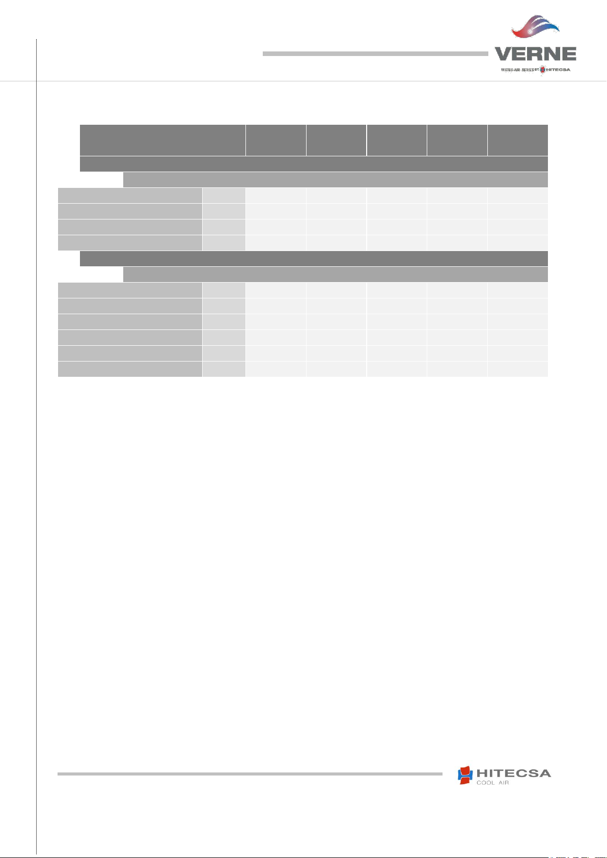
VERNE RANGE
091
121
141
171
201
WPHBA / WPHA
COOLING CAPACITIES
Nominal Cooling Capacity (1)
kW
2.33
3.15
3.88
4.79
5.76
Power Input (3)
kW
0.75
1.00
1.14
1.18
1.64
EER Coefficient
kW / kW
3.12
3.15
3.39
4.05
3.51
Energy Class
A A A A
A
WPHBA (Heat Pump Units)
HEAT CAPACITIES
Heat Capacity (2)
kW
2.83
3.87
4.7
5.56
7.11
Heat Power Input (3)
kW
0.8
1.05
1.31
1.26
1.79
COP Coefficient
kW / kW
3.56
3.69
3.59
4.41
3.97
Water flow
m³/h
0.6
0.7
0.9
1.0
1.3
Pressure Drop
kPa
8.72
15.46
22.42
17.9
26.81
Energy Class
A A A A
A
TECHNICAL SPECIFICATIONS
1) Nominal Cold Conditions, calculated according to UNE-EN 14511:2013 standard, 35ºC of outdoor temperature, 12ºC of inlet water temperature
and 7ºC of outlet water temperature.
2) Nominal Heat Conditions (mean temperatures), calculated according to UNE-EN 14511:2013 standard, 7ºC dry bulb / 6ºC wet bulb of outdoor
temperature, 30ºC of inlet water temperature and 35ºC of outlet water temperature.
3) Total power input at nominal conditions. Calculated according to UNE-EN 14511:2013 regulation.
4) GWP: Global Warming Potential (climatic) of 1 kg of greenhouse gas relative to 1 kg of CO2, calculated in terms of 100-year warming potential.
8
IOM_WPHBA-WPHA_091a1201_207954_180610_EN
COMPACT HORIZONTAL PACKAGED WATER-TO-AIR UNITS
WPHBA / WPHA
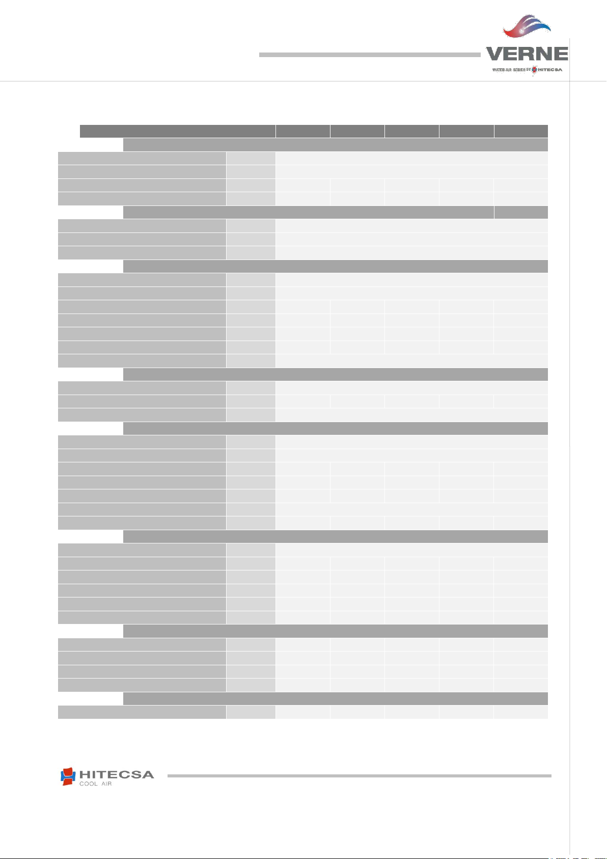
VERNE RANGE
091
121
141
171
201
REFRIGERANT
Type
R-410A
Global Warming Potential (GWP) (4) 2088
Refrigerant load WPHA
kg
0.4
0.4
0.4
0.5
0.55
Refrigerant load WPHBA
kg
0.7
0.6
0.9
1.5
1.2
COMPRESSOR
Type
Rotational
Quantity
1
Voltage
V / ~ / Hz
230 / I / 50
EVAPORATOR FAN
Type
Centrifugal. double aspiration (integrated motor)
Quantity
1
Model 180 / 184
180 / 184
7 / 7
7 / 7
180 / 184
Air flow
m³/h
500
600
700
900
1100
Available Pressure
Pa
25
25
54
25
25
Motor power
W
115
115
72
72
150
Voltage
V / ~ / Hz
230 / I / 50
INDOOR HEAT EXCHANGER
Type
Coil with aluminium fins and copper tube
Frontal area
m²
0.165
0.165
0.165
0.188
0.188
Fin spacing
mm - (")
2.1 - 3/8
EXTERNAL HEAT EXCHANGER
Type
Brazed plates
Quantity
1
Water flow WPHA
m³/h
0.5
0.7
0.9
1.0
1.3
Water flow WPHBA
m³/h
0.6
0.7
0.9
1.0
1.3
Pressure Drop
kPa
8.72
15.46
22.42
17.9
26.81
Water connections (male gas thread)
(")
3/4
Number of plates
16
16
16
22
22
GENEREAL FEATURES FOR THE ELECTRICAL INSTALLATION
Voltage
V / ~ / Hz
230 / I + N / 50
Max. Power Input (Cold)
kW
1.0
1.3
1.5
1.5
2.2
Max. Current Input (Cold)
A
4.4
5.8
7.0
8.0
11.3
Max. Power Input (Heat)
kW
0.9
1.2
1.4
1.4
1.9
Max. Current Input (Heat)
A
4.0
5.4
6.0
7.2
10.0
Start up current
A
19.6
21.6
34.4
26.5
43.7
DIMENSIONS AND WEIGHT
Length
mm
1055
1055
1055
1055
1055
Width
mm
560
560
560
560
560
Height
mm
410
410
410
470
470
Weight
kg
60
62
65
75
77
SOUND LEVEL
Sound pressure at 2 m
dB (A)
58
58
59
60
62
TECHNICAL SPECIFICATIONS
(4) GWP: Global Warming Potential (climatic) of 1 kg of greenhouse gas relative to 1 kg of CO2, calculated in terms of 100-year warming potential.
9
IOM_WPHBA-WPHA_091a1201_207954_180610_EN
COMPACT HORIZONTAL PACKAGED WATER-TO-AIR UNITS
WPHBA / WPHA
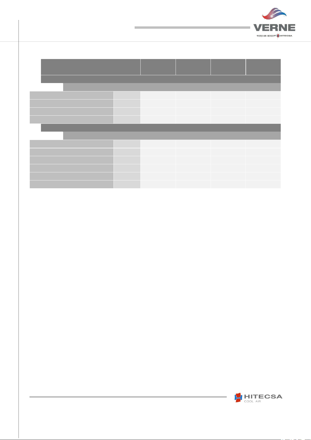
VERNE RANGE
251
351
401
501
WPHBA / WPHA
COOLING CAPACITIES
Nominal cooling capacity (1)
kW
7.42
11.3
13.08
16.35
Power Input (3)
kW
1.87
2.99
3.44
3.48
EER Coefficient
kW / kW
3.97
3.78
3.8
4.7
Energy class
A A A
A
WPHBA (Heat Pump Units)
HEATING CAPACITIES
Heating capacity (2)
kW
9.22
14.15
16.34
18.89
Heat Power Input (3)
kW
1.86
3.1
3.6
3.96
COP Coefficient
kW / kW
4.96
4.56
4.54
4.77
Water flow
m³/h
1.6
2.6
2.9
3.5
Pressure Drop
kPa
15.07
34.3
44.8
21.25
Energy class
A A A
A
TECHNICAL SPECIFICATIONS
1) Nominal Cold Conditions, calculated according to UNE-EN 14511:2013 standard, 35ºC of outdoor temperature, 12ºC of inlet water temperature
and 7ºC of outlet water temperature.
2) Nominal Heat Conditions (mean temperatures), calculated according to UNE-EN 14511:2013 standard, 7ºC dry bulb / 6ºC wet bulb of outdoor
temperature, 30ºC of inlet water temperature and 35ºC of outlet water temperature.
3) Total power input at nominal conditions. Calculated according to UNE-EN 14511:2013 regulation.
4) GWP: Global Warming Potential (climatic) of 1 kg of greenhouse gas relative to 1 kg of CO2, calculated in terms of 100-year warming potential.
10
IOM_WPHBA-WPHA_091a1201_207954_180610_EN
COMPACT HORIZONTAL PACKAGED WATER-TO-AIR UNITS
WPHBA / WPHA
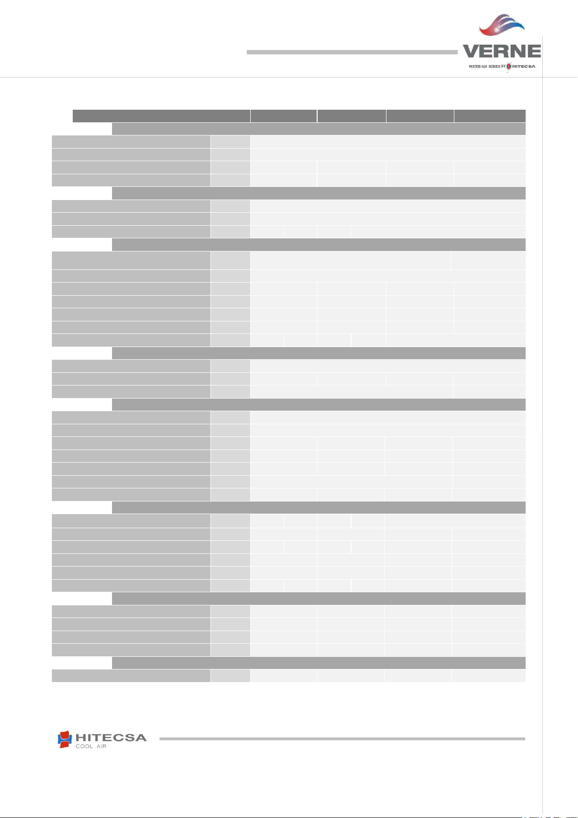
VERNE RANGE
251
351
401
501
REFRIGERANT
Type
R-410A
Global Warming Potential (GWP) (4) 2088
Refrigerant load WPHA
kg
0.7
0.8
0.8
2.0
Refrigerant load WPHBA
kg
1.7
1.8
2.8
3.8
COMPRESSOR
Type Rotative
Scroll
Quantity
1
Voltage
V / ~ / Hz
230/1/50
400/3/50
230/1/50
400/3/50
400/3/50
EVAPORATOR FAN
Type Centrifugal. double aspiration (integrated motor)
Centrifugal.
transmission motor
Quantity
1
Model 7 / 7
9 / 9
10 / 10
10 / 10
Air flow
m³/h
1500
2000
2300
2800
Available Pressure
Pa
37
37
60
50
Motor power
W
147
200
245
550
Voltage
V / ~ / Hz
230/1/50
400/3/50
230/1/50
400/3/50
400/3/50
INDOOR HEAT EXCHANGER
Type
Coil with aluminium fins and copper tube
Frontal area
m²
0.252
0.252
0.252
0.45
Fin spacing
mm - (")
1.8 - 3/8
2.1 - 3/8
EXTERNAL HEAT EXCHANGER
Type
Brazed plates
Quantity
1
Water flow WPHA
m³/h
1.6
2.6
2.9
3.5
Water flow WPHBA
m³/h
1.6
2.6
2.9
3.5
Pressure Drop
kPa
15.07
34.3
44.8
21.25
Water connections (male gas thread)
(")
3/4
1 1/4
Number of plates
42
42
42
32
GENEREAL FEATURES FOR THE ELECTRICAL INSTALLATION
Voltage
V / ~ / Hz
230/1/50
400/3+N/
50
230/1/50
400/3+N/
50
400/3+N/50
Max. Power Input (Cold)
kW
2.6
5.2
5.0
6.3
Max. Current Input (Cold)
A
13.4
6.9
19.3
9.0
8,5
10,9
Max. Power Input (Heat)
kW
2.6
4.8
4.6
5.4
Max. Current Input (Heat)
A
11.3
13.4
6.9
19.3
Start up current
A
61.3
27.0
88.0
50.8
61,3
71,3
DIMENSIONS AND WEIGHT
Length
mm
1135
1135
1135
1385
Width
mm
670
670
670
940
Height
mm
530
530
530
620
Weight
kg
90
110
115
160
SOUND LEVEL
Sound pressure at 2 m
dB (A)
63
64
64
65
TECHNICAL SPECIFICATIONS
11
IOM_WPHBA-WPHA_091a1201_207954_180610_EN
COMPACT HORIZONTAL PACKAGED WATER-TO-AIR UNITS
WPHBA / WPHA
VERNE RANGE
701
751
1001
1201
WPHA
COOLING CAPACITIES
Nominal cooling capacity (1)
kW
19.77
25.18
33.9
39.96
Power Input (3)
kW
4.46
6.11
7.78
9.25
EER Coefficient
kW / kW
4.44
4.12
4.36
4.32
Energy class
A A A A
WPHBA (Heat Pump Units)
HEATING CAPACITIES
Heating capacity (2)
kW
23.11
30.6
39.82
46.41
Heat Power Input (3)
kW
4.94
7.01
8.37
10.1
COP Coefficient
kW / kW
4.68
4.37
4.76
4.6
Water flow
m³/h
4.3
5.5
7.6
8.7
Pressure Drop
kPa
30.9
49.03
37.1
49.35
Energy class
A A A A
TECHNICAL SPECIFICATIONS
1) Nominal Cold Conditions, calculated according to UNE-EN 14511:2013 standard, 35ºC of outdoor temperature, 12ºC of inlet water temperature
and 7ºC of outlet water temperature.
2) Nominal Heat Conditions (mean temperatures), calculated according to UNE-EN 14511:2013 standard, 7ºC dry bulb / 6ºC wet bulb of outdoor
temperature, 30ºC of inlet water temperature and 35ºC of outlet water temperature.
3) Total power input at nominal conditions. Calculated according to UNE-EN 14511:2013 regulation.
4) GWP: Global Warming Potential (climatic) of 1 kg of greenhouse gas relative to 1 kg of CO2, calculated in terms of 100-year warming potential.
12

IOM_WPHBA-WPHA_091a1201_207954_180610_EN
COMPACT HORIZONTAL PACKAGED WATER-TO-AIR UNITS
WPHBA / WPHA
VERNE RANGE
701
751
1001
1201
REFRIGERANT
Type
R-410A
Global Warming Potential (GWP) (4) 2088
Refrigerant load WPHA
kg
1.6
1.7
2.4
3.0
Refrigerant load WPHBA
kg 4 4.2
6.1
6.3
COMPRESSOR
Type
Scroll
Quantity
1
Voltage
V / ~ / Hz
400/3/50
EVAPORATOR FAN
Type
Centrifugal. transmission motor
Quantity
1
Model 10 / 10
12 / 9
12 / 12
15 / 15
Air flow
m³/h
3400
4300
6200
7000
Available Pressure
Pa
50
62
75
75
Motor power
W
550
750
1500
1100
Voltage
V / ~ / Hz
400/3/50
INDOOR HEAT EXCHANGER
Type
Coil with aluminium fins and copper tubes
Frontal area
m²
0.45
0.45
0.84
0.84
Fin spacing
mm - (")
2.1 - 3/8
EXTERNAL HEAT EXCHANGER
Type
Brazed plates
Quantity
1
Water flow WPHA
m³/h
4.3
5.5
7.5
8.7
Water flow WPHBA
m³/h
4.3
5.5
7.6
8.7
Pressure Drop
kPa
30.9
49.03
37.1
49.35
Water connections (male gas thread)
(")
1 1/4
Number of plates
32
32
52
52
GENEREAL FEATURES FOR THE ELECTRICAL INSTALLATION
Voltage
V / ~ / Hz
400 / 3+N / 50
Max. Power Input (Cold)
kW
8.9
10.2
13.4
14.8
Max. Current Input (Cold)
A
15.4
17.5
23.0
25.3
Max. Power Input (Heat)
kW
7.7
8.5
12.0
13.0
Max. Current Input (Heat)
A
15.4
17.5
23.0
25.3
Start up current
A
88.3
126.6
128.5
149.6
DIMENSIONS AND WEIGHT
Length
mm
1385
1385
1930
1930
Width
mm
940
940
1040
1040
Height
mm
620
620
690
690
Weight
kg
160
180
230
250
SOUND LEVEL
Sound pressure at 2 m
dB (A)
68
68
69
70
TECHNICAL SPECIFICATIONS
(4) GWP: Global Warming Potential (climatic) of 1 kg of greenhouse gas relative to 1 kg of CO2, calculated in terms of 100-year warming potential.
13
IOM_WPHBA-WPHA_091a1201_207954_180610_EN
COMPACT HORIZONTAL PACKAGED WATER-TO-AIR UNITS
WPHBA / WPHA
WPHBA EC Fan
91
121
141
171
201
251
351
401
501
701
751
1001
1201
Type
RADIAL with EC motor (Plug-Fan type)
Quantity / Size
- / mm
1/190
1/190
1/190
1/250
1/250
1/310
1/310
1/310
1/400
1/400
1/400
1/450
1/450
Nominal Electrical Specifications (for a fan)
Power supply
V/~/Hz
230V / 1~ / 50Hz
400V / 3~ / 50Hz
Motor nominal power
kW
0.2
0.2
0.2
0.5
0.5
1.4
2.5
2.5
2.4
2.4
2.4
2.0
2.0
Max. Current
(400V)
A
1.9
1.9
1.9
2.2
2.2
6.0
3.8
3.8
3.7
3.7
3.7
3.2
3.2
Max. Speed
r.p.m.
4240
4240
4240
3080
3080
2920
3640
3640
2400
2400
2400
1880
1880
Nominal Operation Conditions
Nominal air flow
m3/h
500
600
700
900
1100
1500
2000
2300
2800
3400
4300
6200
7000
Available Pressure
Pa
25
25
25
25
25
25
37
50
50
62
62
75
75
Total power input
kW
0.04
0.059
0.084
0.057
0.084
0.113
0.226
0.309
0.2
0.307
0.513
0.827
1.107
Speed
rpm
2500
2924
3365
1368
1640
1190
1558
1777
1044
1242
1509
1476
1643
Total sound power
(Lw)
dBA
70
74
77
63
67
65
73
76
67
71
77
81
84
Operating Limits Values
Max. available
pressure
Pa
515
410
300
760
700
1050
1630
1580
1150
1100
975
580
400
Max. sound power
dBA
77
77
78
82
80
89
94
93
90
88
87
84
86
Sound power at 400Pa
dBA
75
76 - 73
74
75
78
80
74
76
79
82
86
TECHNICAL SPECIFICATIONS
OPCIONAL MOTOR EC
14
IOM_WPHBA-WPHA_091a1201_207954_180610_EN
COMPACT HORIZONTAL PACKAGED WATER-TO-AIR UNITS
WPHBA / WPHA
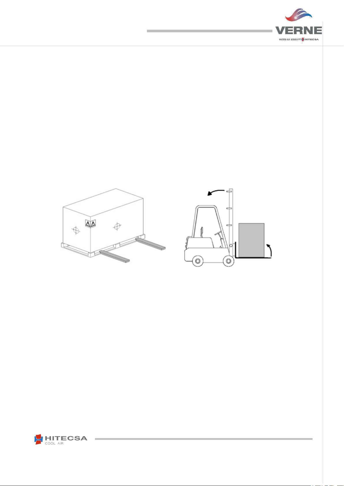
Fig.2
Fig.1
TRANSPORT & RECEPTION
INSPECTION AT RECEPTION
It is advisable to examine the equipment carefully at the time of its reception.
Check that the equipment has not been damaged during transport and it has been supplied complete with all
parts specified in the order and/or with the options specified in the order. If this is not the case, contact the
transport company immediately. (First 48h).
Verify the correct voltage of the nameplate and make sure it is in accordance with local power supply.
In case of any flaw or anomaly detected, please contact HITECSA.
RIGGING
Before moving the unit, make sure that all panels are well fixed.
Raise and set down the equipment carefully.
Do not tilt the unit more than 15 degrees during transportation. (Fig. 2).
Always transport the unit in its original packaging to the place of installation.
All units come with a particular rigging diagram of that model, similar to the one shown below. Be sure to hoist
the machine through the points indicated in the diagram.
Make sure that the unit is balanced, stable and without any deformations when it is lifted.
STORAGE
If the equipment is going to be stored before the installation, please follow the instructions below in order to avoid damages,
corrosion or deterioration:
Move it carefully.
Do not place the machine in places exposed to ambient temperature above 50ºC and preferably keep the unit away
from direct sunlight.
Avoid placing the unit with plastic wrapping protection under the sun, as the pressure of the circuits could assume
values that could lead to the intervention of the safety valves.
In addition, when cooling, water condensation occurs inside the machine and the plastic wrap.
Avoid placing other objects on top of the unit (unless it is done within the limits of the overlap planes indicated on the
packaging, etc. Follow these indications).
Avoid prolonged storage, before installation, water inlet, dust and objects in general due to invasion or biological,
meteorological and/or human inclemencies.
Minimum storage temperature is: 5ºC.
Maximum relative humidity: 90%.
15
IOM_WPHBA-WPHA_091a1201_207954_180610_EN
COMPACT HORIZONTAL PACKAGED WATER-TO-AIR UNITS
WPHBA / WPHA
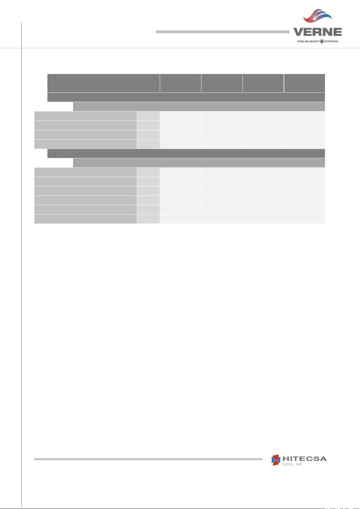
MODELS
1 2 3
4
091
13
13
16
18
121
14
14
16
18
141
14
15
17
19
171
16
17
20
22
201
16
19
20
22
251
21
22
22
25
351
24
26
29
31
401
26
27
30
32
501
38
38
41
43
701
38
38
41
43
751
43
44
46
47
1001
55
56
59
60
1201
61
61
63
65
(3 – 4): Electrical Panel side
INSTALLATION
INSTALLATION LOCATION
Consult and respect the rules and local regulations which regulate the installation of air conditioning systems.
Choose a site without dust and debris.
Respect the appropriate service area for the equipment which will be installed.
Verify that the ground or structure on which the unit will be installed is able to support its weight in operation.
Fit shock absorbers throughout the installation to prevent the transmission of noise and vibration.
Check that the direction of the sound level is not going to disturb anyone.
UNIT SETTLEMENT
Be sure that the unit is correctly levelled.
The bed frame should have the area and the strength to support the weight of the unit.
Be sure that after settlement the unit drain is working properly.
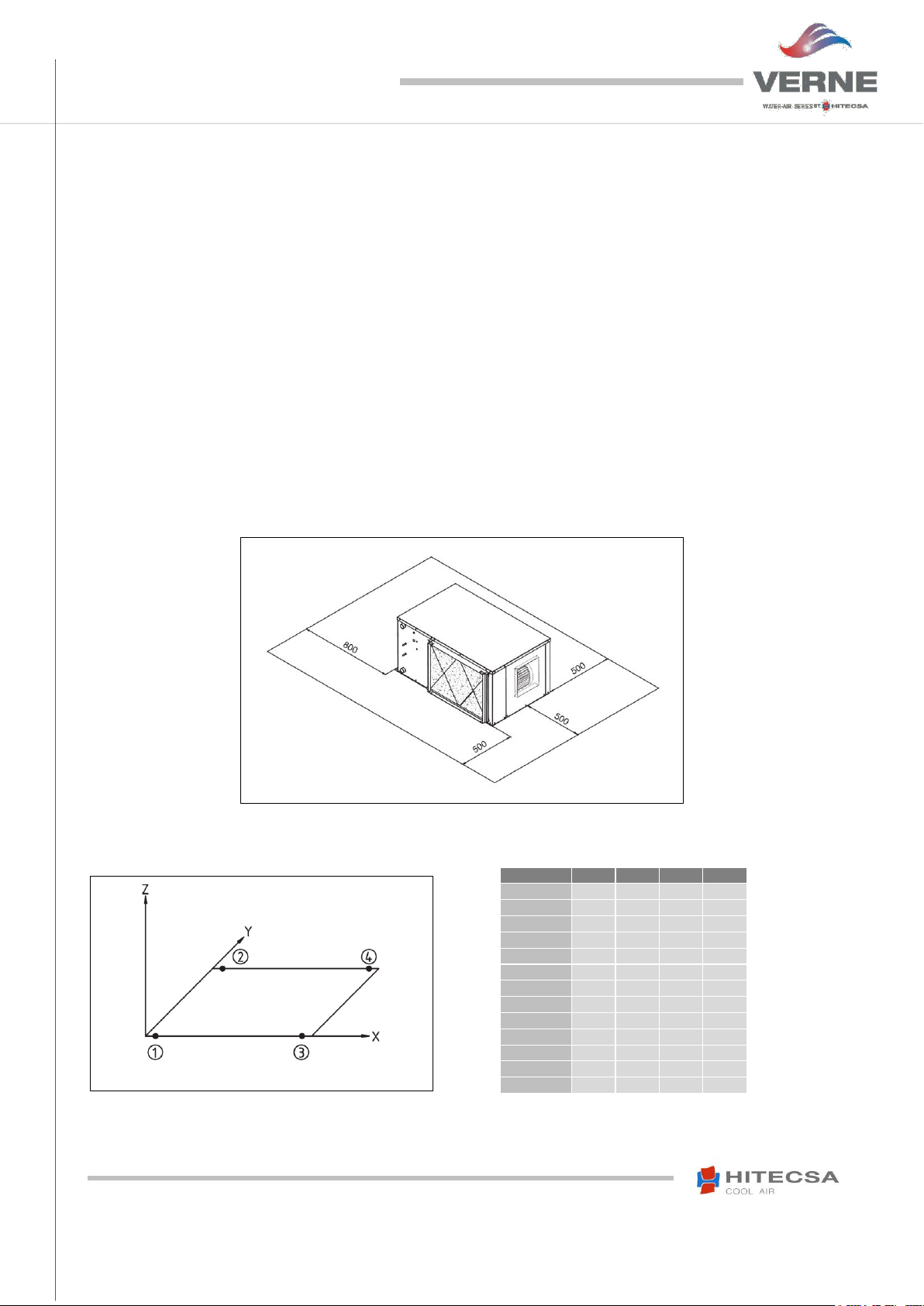
SERVICE AREA (mm)
Make sure to respect the following measurements for the correct operating of the unit.
WEIGHT DISTRIBUTION (kg)
16
IOM_WPHBA-WPHA_091a1201_207954_180610_EN
COMPACT HORIZONTAL PACKAGED WATER-TO-AIR UNITS
WPHBA / WPHA
Legend
8 Evaporator turbine
DIMENSIONS (mm)
MODEL A B C D
091-121
131
108
232
86
141
213
56
238
86
WEIGHT (kg)
MODEL
NET WEIGHT
PACKAGED WEIGHT
091
60
75
121
62
77
141
65
80
INSTALLATION
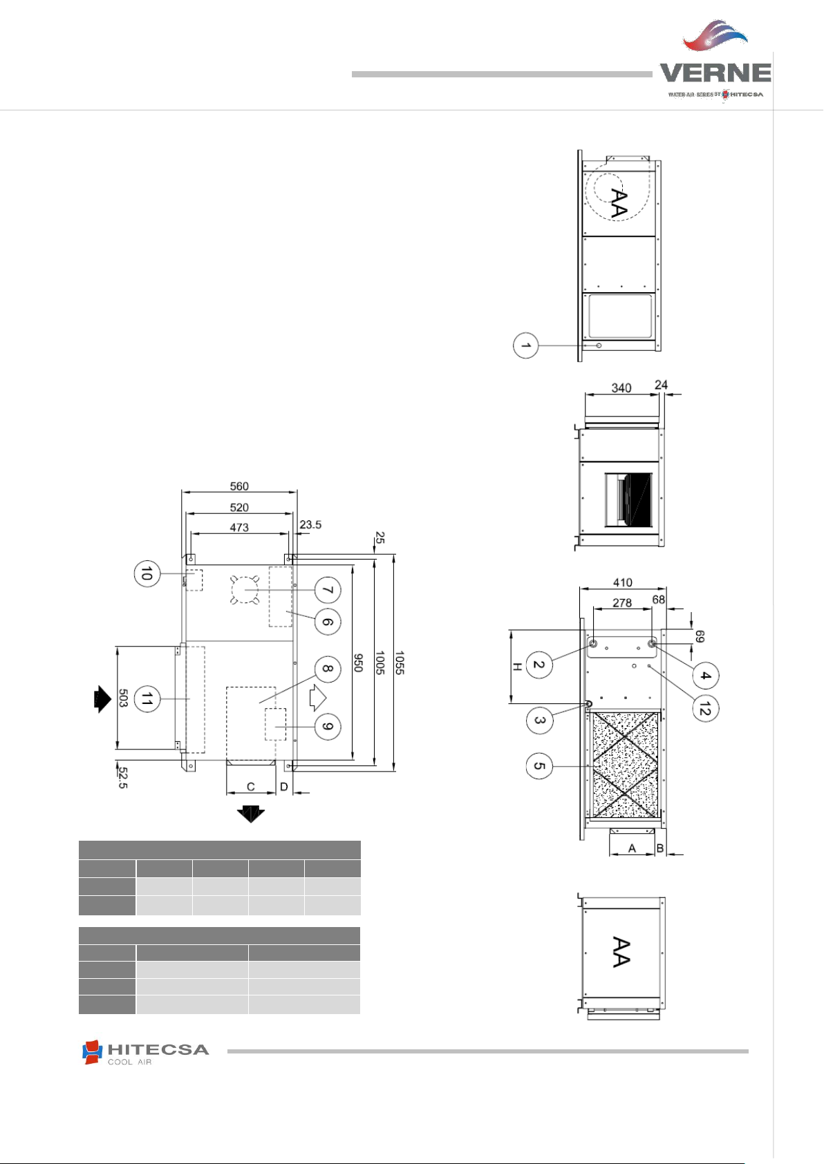
DIMENSIONS AND WEIGHT
Standard Fan
Models 091 – 141
1 Electrical connections input
2 Water inlet
3 External drainage 3/4’’ male
4 Water outlet
5 Air filter
6 Electrical panel
7 Compressor
9 Turbine engine
10 External coil
11 Internal coil
12 Pressure valve connection (optional)
AA Panel access
17

IOM_WPHBA-WPHA_091a1201_207954_180610_EN
COMPACT HORIZONTAL PACKAGED WATER-TO-AIR UNITS
WPHBA / WPHA
Legend
8 Evaporator turbine
DIMENSIONS (mm)
MODEL A B C D
171
213
100
238
86
201
131
153
232
86
WEIGHT (kg)
MODEL
NET WEIGHT
PACKAGED WEIGHT
171
75
90
201
77
92
INSTALLATION
DIMENSIONS AND WEIGHT
Standard Fan
Models 171 - 201
1 Electrical connections input
2 Water inlet
3 External drainage 3/4’’ male
4 Water outlet
5 Air filter
6 Electrical panel
7 Compressor
9 Turbine engine
10 External coil
11 Internal coil
12 Pressure valve connection (optional)
AA Panel access
18

IOM_WPHBA-WPHA_091a1201_207954_180610_EN
COMPACT HORIZONTAL PACKAGED WATER-TO-AIR UNITS
WPHBA / WPHA
Legend
8 Evaporator turbine
WEIGHT (kg)
MODEL
NET WEIGHT
PACKAGED WEIGHT
251
90
105
351
110
125
401
115
130
DIMENSIONS (mm)
MODEL A B C D
251
213
146
238
98
351
266
88
306
98
401
293
37
238
98
INSTALLATION
DIMENSIONS AND WEIGHT
Standard Fan
Models 251 - 401
1 Electrical connections input
2 Water inlet
3 External drainage 3/4’’ male
4 Water outlet
5 Air filter
6 Electrical panel
7 Compressor
9 Turbine engine
10 External coil
11 Internal coil
12 Pressure valve connection (optional)
13 Main switch
AA Panel access
19

IOM_WPHBA-WPHA_091a1201_207954_180610_EN
COMPACT HORIZONTAL PACKAGED WATER-TO-AIR UNITS
WPHBA / WPHA
8 Evaporator turbine
Legend
DIMENSIONS (mm)
MODEL A B C D
501-701
293
128
338
190
751
345
65
315
190
WEIGHT (kg)
MODEL
NET WEIGHT
PACKAGED WEIGHT
501
160
175
701
160
175
751
180
195
INSTALLATION
DIMENSIONS AND WEIGHT
Standard Fan
Models 501 - 751
1 Electrical connections input
2 Water inlet
3 External drainage 3/4’’ male
4 Water outlet
5 Air filter
6 Electrical panel
7 Compressor
9 Turbine engine
10 External coil
11 Internal coil
12 Pressure valve connection (optional)
13 Main switch
AA Panel access
20

IOM_WPHBA-WPHA_091a1201_207954_180610_EN
COMPACT HORIZONTAL PACKAGED WATER-TO-AIR UNITS
WPHBA / WPHA
Legend
8 Evaporator turbine
DIMENSIONS (mm)
MODEL A B C D
1001
347
117
402
200
1201
409
28
478
163
WEIGHT (kg)
MODEL
NET WEIGHT
PACKAGED WEIGHT
1001
230
245
1201
250
265
INSTALLATION
DIMENSIONS AND WEIGHT
Standard Fan
Models 1001 - 1201
1 Electrical connections input
2 Water inlet
3 External drainage 3/4’’ male
4 Water outlet
5 Air filter
6 Electrical panel
7 Compressor
9 Turbine engine
10 External coil
11 Internal coil
12 Pressure valve connection (optional)
13 Main switch
AA Access Panel
21

IOM_WPHBA-WPHA_091a1201_207954_180610_EN
COMPACT HORIZONTAL PACKAGED WATER-TO-AIR UNITS
WPHBA / WPHA
Legend:
AA Access Panel
DIMENSIONS (mm)
MODELS
A B C D 091
227
82
227
74
121
227
82
227
74
141
227
82
227
74
WEIGHT(kg)
MODELS
NET WEIGHT
PACKAGED WEIGHT
091
60
75
121
62
77
141
65
80
INSTALLATION
DIMENSIONS AND WEIGHT
EC RADIAL FAN
Models 091 - 141
1. Electrical connections input
2. Water inlet
3. External drainage Ø 3/4” male
4. Water outlet
5. Air filter
6. Manoeuvre
7. Compressor
8. EC fan
9. Condenser coil
10. Evaporator coil
11. Pressure valve connection (optional)
12. Main switch
22

IOM_WPHBA-WPHA_091a1201_207954_180610_EN
COMPACT HORIZONTAL PACKAGED WATER-TO-AIR UNITS
WPHBA / WPHA
Legend:
DIMENSIONS (mm)
MODELS
A B C D 171
300
76
238
94
201
300
76
238
94
WEIGHT (kg)
MODELS
NET WEIGHT
PACKAGED WEIGHT
171
75
90
201
77
92
INSTALLATION
DIMENSIONS AND WEIGHT
EC RADIAL FAN
Models 171 – 201
1. Electrical connections input
2. Water inlet
3. External drainage Ø 3/4” male
4. Water outlet
5. Air filter
6. Manoeuvre
7. Compressor
8. EC fan
9. Condenser coil
10. Evaporator coil
11. Pressure valve connection (optional)
12. Main switch
AA Access Panel
23

IOM_WPHBA-WPHA_091a1201_207954_180610_EN
COMPACT HORIZONTAL PACKAGED WATER-TO-AIR UNITS
WPHBA / WPHA
Legend:
AA Access Panel
DIMENSIONS (mm)
MODELS
A B C D 251
352
81
352
88
351
352
81
352
88
451
352
81
352
88
WEIGHT (kg)
MODELS
NET WEIGHT
PACKAGED WEIGHT
251
90
105
351
110
115
401
115
130
INSTALLATION
DIMENSIONS AND WEIGHT
EC RADIAL FAN
Models 251 – 451
1. Electrical connections input
2. Water inlet
3. External drainage Ø 3/4” male
4. Water outlet
5. Air filter
6. Manoeuvre
7. Compressor
8. EC fan
9. Condenser coil
10. Evaporator coil
11. Pressure valve connection (optional)
12. Main switch
24

IOM_WPHBA-WPHA_091a1201_207954_180610_EN
COMPACT HORIZONTAL PACKAGED WATER-TO-AIR UNITS
WPHBA / WPHA
Legend:
AA Access Panel
DIMENSIONS (mm)
MODELS
A B C
D
501
502
48
452
222
701
502
48
452
222
751
502
48
452
222
WEIGHT (kg)
MODELS
NET WEIGHT
PACKAGED WEIGHT
501
160
175
701
160
175
751
180
195
INSTALLATION
DIMENSIONS AND WEIGHT
EC RADIAL FAN
Models 501 - 751
1. Electrical connections input
2. Water inlet
3. External drainage Ø 3/4” male
4. Water outlet
5. Air filter
6. Compressor
7. Manoeuvre
8. EC fan
9. Condenser coil
10. Evaporator coil
11. Pressure valve connection (optional)
12. Main switch
25

IOM_WPHBA-WPHA_091a1201_207954_180610_EN
COMPACT HORIZONTAL PACKAGED WATER-TO-AIR UNITS
WPHBA / WPHA
Legend:
WEIGHT (kg)
MODELS
NET WEIGHT
PACKAGED WEIGHT
1001
230
245
1201
250
265
INSTALLATION
DIMENSIONS AND WEIGHT
EC RADIAL FAN
Models 1001 - 1201
1. Electrical connections input
2. Water inlet
3. External drainage Ø 3/4” male
4. Water outlet
5. Air filter
6. Compressor
7. Manoeuvre
8. EC fan
9. Condenser coil
10. Evaporator coil
11. Pressure valve connection (optional)
12. Main switch
AA Access Panel
26

IOM_WPHBA-WPHA_091a1201_207954_180610_EN
COMPACT HORIZONTAL PACKAGED WATER-TO-AIR UNITS
WPHBA / WPHA
Recommended drain trap
measures
INSTALLATION
DRAINAGE
The indoor drain unit (of condensate water) has a 3/4” MPT connection.
Condensate drain pipe diameter should be equal or larger than the unit drain connection depending on the line length
and general building configuration.
The drainage line should be inclined by minimum 2% for a proper evacuation of the condensation water and to avoid
deposits when possible.
When the drain line is exposed to temperatures below 0 degrees, it is necessary to cover with thermal insulation or
electrical heating wire to avoid water freezing and tube damages.
It is convenient to install the drain trap with proper dimensions (see diagram).
AIR DUCTWORK
Air duct dimensions will be determined according to the airflow and available static pressure of the unit.
Ducts must be designed by qualified technical personnel.
Use ducts made of non-inflammable materials in order to avoid any risk of fire as a consequence of deflagration
gases. It is advisable to use metal sheet duct with insulation.
Use flexible ducts to connect air ducts into the unit and thus avoid vibration and noise transmission.
27
IOM_WPHBA-WPHA_091a1201_207954_180610_EN
COMPACT HORIZONTAL PACKAGED WATER-TO-AIR UNITS
WPHBA / WPHA
GLYCOL ADDITION to WATER (%)
0ºC
-2ºC
-5ºC
-10ºC
-15ºC
-20ºC
-25ºC
-30ºC
ETHYLENE GLYCOL
0%
6%
14%
24%
31%
36%
41%
45%
PROPYLENE GLYCOL
0%
7%
15%
25%
33%
39%
44%
48%
INSTALLATION
HYDRAULIC INSTALLATION
The selection of the components and the installation shall be made by a qualified installer according to the valid local
legislation and the good practice rules.
Make sure that you are aware of all the local rules and regulations for hydraulic installations and that you comply with
them.
The design and calculation of the pipes shall be realised keeping in mind that the pressure drop of the installation shall
never exceed the pressure drop that would overcome the pump of the installation. A wrong design with inadequate
pressure drops in the section pipes that lead to the indoor units would entail the malfunction of some of them.
The installation shall be completed according to the hydraulic connection diagram (please refer to the below shown
diagram).
Proceed to the installation of a water filter that is provided with an inner net to retain the particles with a maximum
diameter of 0.5mm.
A proper maintenance of the filter and the flow switch at an appropriate periodicity shall be completed to avoid deposits
that could block them.
Comply with the stated indications regarding the water inlet and outlet of the unit and install a by-pass valve if necessary.
WATER FILLING
Use water at around 20ºC to fill the hydraulic circuit. After the system has been drained, the pressure level must be as
stated in the installation project or according to the pressure level of the main installation. In case when the water installation
of the unit is going to be added to an existing water installation, the main installation probably will comprise a filling system
already.
Attention: An expansion tank with a bigger capacity will be required according to the filled water volume.
Drainage
Verify that all the high points of the installation are provided with a bleed valve.
Use the pump during one minute, stop it and drain the circuit (if manual). Wait for another minute and repeat the same
process until there is no more water. 5 to 10 processes like this one may be necessary to drain the system completely for
water.
Remember to drain any other components that include tubes where there might be air pockets (example: differential
switch). They will not work properly with air.
Air in the circuit will produce noises, will entail a lower water flow and a bad performance of the exchanger, etc…
Risk of frost
If the unit or the water installation are exposed to temperatures around 4°C it is necessary to take the appropriate measures
against the risk of frost.
For example:
Mix the water of the installation with glycol.
Protect the pipes with heating cables placed under the insulation lining.
Empty the installation and control at the same time that:
There are no closed valves that may retain water even after draining the installation.
There are no low spots where water may stagnate even after draining; if necessary proceed to purging the installation.
Glycol additions
Keep in mind that the use of glycol solutions increases the pressure drop.
Make sure that the type of glycol you will use is compatible with hydraulic circuit components (pumps, filters, etc.) and that
it is a non-corrosive product.
Make sure that the freezing temperature is below the minimum temperature that the water may reach with a security margin
even when the unit is OFF.
28

IOM_WPHBA-WPHA_091a1201_207954_180610_EN
COMPACT HORIZONTAL PACKAGED WATER-TO-AIR UNITS
WPHBA / WPHA
Element contained in
water
Concentration by mg/l
Effects of a higher value
Effects of a lower value
Suspended solids
Variable
Can deteriorate the material
No effects are observed
Conductivity
≤ 500 µs/cm
No effects are observed
-
> 500 µs/cm
-
Not recommended
NH3
Must be between 2 and 20
Not recommended
No effects are observed
Chlorides
≤ 300
-
No effects are observed
> 300
Corrosion
-
Iron
≤ 10
No effects are observed
-
> 10
-
Corrosion
Carbonic acids
Must be between 20 and 50
Corrosion
Not recommended
PH
Must be between 6 and 9
Corrosion
No effects are observed
Sulphates
Must be between 70 and 300
No effects are observed
Corrosion
Langelier
Must be between -0,5 and +0,5
Water with tendency to create
incrustations
Water with corrosive
tendency
INSTALLATION
THE HYDRAULIC CIRCUIT AND ITS COMPONENTS
The plate heat exchanger is the most fragile part of the hydraulic circuit. Therefore it is very important that the units provided
with a plate exchanger work in an open hydraulic circuit and in a closed thermal circuit within the control values as stated
in the following chart. The Langelier index shall not be exceeded (downwards or upwards) as in such a situation corrosive
or encrusting water may be produced. That would geopardize the component and the unit warranty would not apply. In
such a case a special exchanger suitable for this quality of water would be necessary.
Shut-off valves
Installed at the inlet and the outlet of each component, they allow to carry out the maintenance operations without having
to empty the installation.
Thermometers and pressure gauges
Installed at the inlet and the outlet of the main elements. They make maintenance and control operations easier.
Air release valves
Installed at the highest points of the installation. They enable air drainage of the circuit.
Drainage valves
Install them at all the low points to empty the circuit.
Supports
The weight of the pipes must not be supported by the connections of the unit. Therefore supporting rings shall be used.
Expansion vessel
It maintains the correct pressure of the installation, we recommend filling at 2.15 bar, when the water temperature varies
from cold to pump and vice versa. The expansion vessel has to be dimensioned according to the water content of the
installation.
In special circumstances it may be necessary to install one or more additional vessels even tif the unit already is equipped
with one.
Security devices
The installation of the following safety devices is MANDATORY when these elements ARE NOT included as standard
features. Not complying with this condition will entail the LOSS OF WARRANTY.
Water filter
At the water inlet of the unit, to protect the heat exchanger or other critical components from obstructions and/or clogging.
Flow switch
It aims at protecting the plate heat exchanger from breakage caused by a too low water flow that would make the equipment
completely inoperative.
29

IOM_WPHBA-WPHA_091a1201_207954_180610_EN
COMPACT HORIZONTAL PACKAGED WATER-TO-AIR UNITS
WPHBA / WPHA
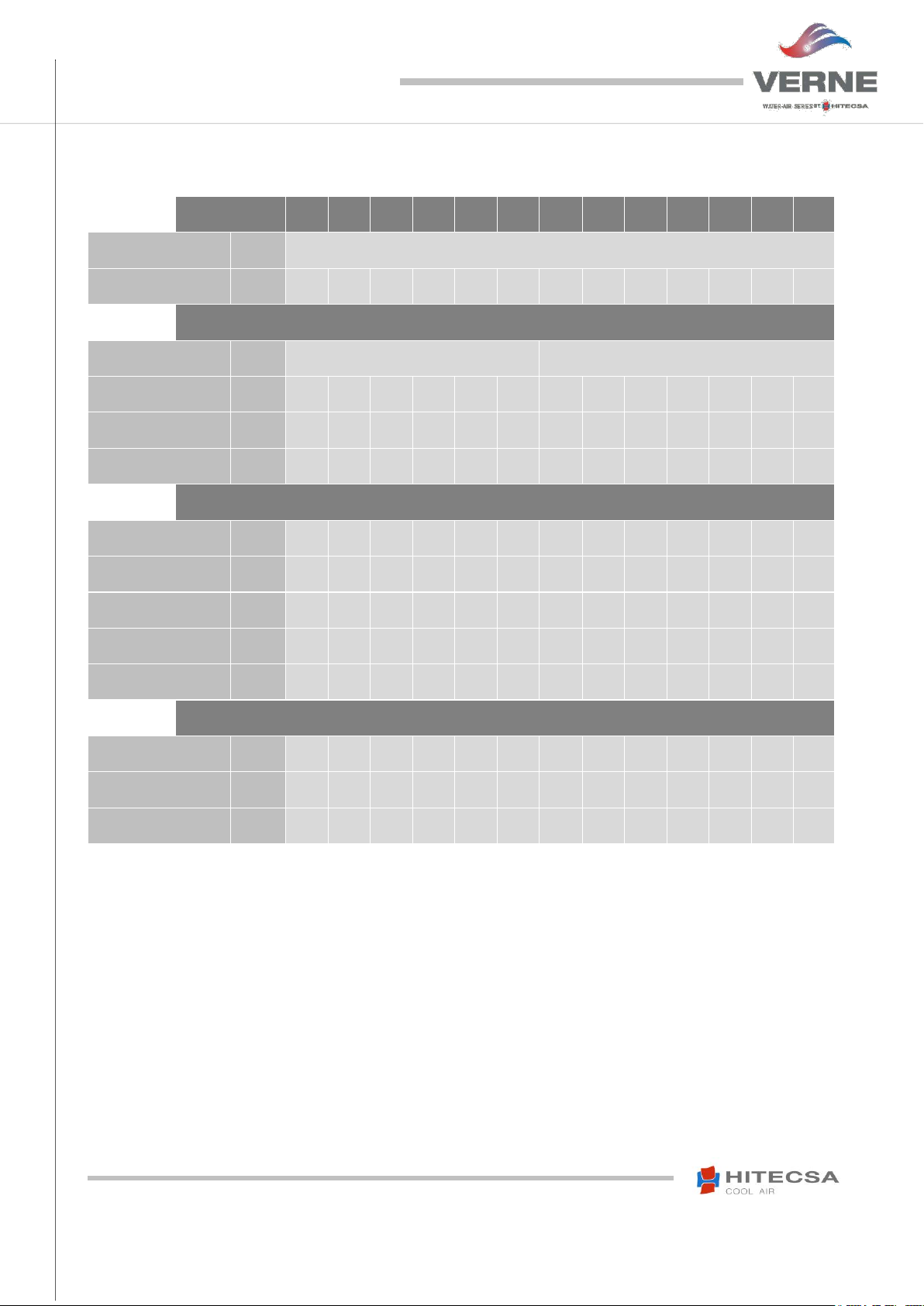
VERNE
range
91
121
141
171
201
251
351
401
501
701
751
1001
1201
Water Connections (male gas thread)
"
¾”
1 ¼”
Model of the supplied flow switch
-
SF1RE
SF1K
Recommended tube diameter
"
1"
1 ¼”
1 ½”
2"
3"
Minimum Flow Setting (Disconnection - Off)
m³/h
0,2
0,4
0,7
0,8
1,1
1,4
2,4
2,7
3,2
3,6 5 6
7,4
Nominal Flow Setting (Connection - On)
m³/h
0,6
0,7
0,9 1 1,3
1,6
2,6
2,9
3,5
4,3
5,5
7,6
8,7
SF1RE models 091 - 251
SF1K models 351 - 1201
Tube
Max. Q
Min. setting
Max. setting
Tube
Max. Q
Min. setting
Max. setting
ø
m3/h
Off (On) m3/h
Off (On) m3/h
ø
m3/h
Off (On) m3/h
Off (On) m3/h
1"
3,6
0,2 (0,6)
1,0 (1,1) 1 3,6
0,6 (1,0)
2,0 (2,1)
1 1/4"
6
0,25 (0,9)
1,4 (1,6)
1 1/4"
6
0,8 (1,3)
2,8 (3,0)
1 1/2"
9
0,5 (1,2)
1,6 (2,2)
1 1/2"
9
1,1 (1,7)
3,7 (4,0)
2"
15
0,9 (2,3)
3,6 (4,1)
2"
15
2,2 (3,1)
5,7 (6,1)
2 1/2"
24
1,2 (3,1)
4,9 (5,5)
2 1/2"
24
2,7 (4,0)
6,5 (7,0)
3"
36
2,1 (4,9)
7,4 (8,2)
3"
36
4,3 (6,2)
10,7 (11,4)
1. Loosen until water comes out. Then,
tighten the nuts again.
INSTALLATION
Differential switch
We will use it instead of the flow switch or together with it. Its function is the same as the flow switch’s one. Air pockets
may be generated after filling the circuit with water. We will have to make sure that there is no air to garanty that this
component will work properly: we will proceed to purging by loosening the nuts of the tubes (please see below, 1.).
The warranty will not cover any damages to the plate exchanger caused by air in the switch that would be responsible
for its malfunction.
INSTALLATION OF THE FLOW SWITCH AS AN OPTION
It is compulsory to mount the flow switch at the water outlet of the unit. The water flow shall be laminar to make sure
that the flow switch works properly: Install the flow switch on a straight section of the tube where there is no section change.
The distance to the switch shall be minimum 6 times the diameter (D) of the tube and at the outlet there shall be a distance
of minimum 3 times the diameter of the tube. No other component or accessory shall be installed on that tube. If you use
a flow switch from another supplier (not delivered by Hitecsa), refer to the instructions of the producer and respect the
dimensions as previously stated.
Bear in mind that the flow switch has a limited operation range due to the tube diameter. We will need to choose the
diameter of the tube where it will be installed depending on the flow of the unit.
Possible flow switch settings:
Please contact Hitecsa for other possible flow options.
30

IOM_WPHBA-WPHA_091a1201_207954_180610_EN
COMPACT HORIZONTAL PACKAGED WATER-TO-AIR UNITS
WPHBA / WPHA
Tube
Paddle
1" - 1 ½”
1
2" - 2 ½”
1+2
3" - 4”
1+2+3
INSTRUCTIONS
VERIFICATION OF THE PADDLE MOVEMENT
ELECTRICAL CONNECTIONS
When screwing (A) make sure that the
inside part of the tube is not invaded (B)
and that the paddle’s position is
perpendicular to the water flow.
After the installation is completed verify that the paddle
can move easily inside the tube. Use a screwdriver to
press slightly until the micro-switch makes “click”, see
above.
The red/white contact (normally in the open position)
will be closed when the necessary flow is detected
and will open up when the flow is lower than the set
value.
When the flow level is matching the minimum allowed
level, adjust the C screw until the red/white contact
opens up (refer to the previous drawing).
ADJUSTING SCREW C
White
Blue
Red
INSTALLATION
Installation of the paddle according to the diameter of the tube:
31

IOM_WPHBA-WPHA_091a1201_207954_180610_EN
COMPACT HORIZONTAL PACKAGED WATER-TO-AIR UNITS
WPHBA / WPHA
1. Antivibratory coupling.
2. Shut off valve
3. Pressostatic valve
4. Solenoid valve ON/OFF
5. Flow switch
6. Mesh filter
7. Condensates drainage network / Empty
8. Solenoid valve ON/OFF with the
compressor
9. Manometer
10. Drain valve
UNIT
WATER SIDE
INSTALLATION
WATER CONNECTIONS WITH THE OPTIONAL PRESSOSTATIC VALVE
Install the by-pass solenoid valve with the optional pressostatic valve in the Heat Pump units.
NOTE: The pressure tap of the pressostatic valve must be connected to the high pressure outlet of the unit. The diagrams
show the connections for the heat pump units. In case of cooling only units, do not mount the solenoid valve.
When mounting the pressostatic valve it is necessary to temporize the operation of the flow switch during 1 minute
when the compressor is starting to make the valve operate.
32

IOM_WPHBA-WPHA_091a1201_207954_180610_EN
COMPACT HORIZONTAL PACKAGED WATER-TO-AIR UNITS
WPHBA / WPHA
WPHA/BA unit
Condensate drain
Dry cooler
Thermometer
Drain Air duct
Shut off valve
Automatic purge
Pressure gauge
Expansion tank
Flexible connection
Water line
Mesh filter
Circulation pump
Flow switch
1
2
3
4
5
6
7
8
9
10
11
12
13
14
15
INSTALLATION
ELEMENTS AND HYDRAULIC CONNECTIONS OF THE INSTALLATION DIAGRAM
33

IOM_WPHBA-WPHA_091a1201_207954_180610_EN
COMPACT HORIZONTAL PACKAGED WATER-TO-AIR UNITS
WPHBA / WPHA
1. Main power supply :
* 091- 251 Single phase (phase + Neutral)
** 351-1201 Three-phase + Neutral
2. Ground
3. Delayed-action fuses or circuit breaker D
curve.
4. Main switch
5. TH-Tune control
TH-TUNE CONNECTION:
- Two power cables 230 VAC (L+N)
- One twisted pair AWG 20/22 shielded with drain wire to
GND.
pGD CONNECTION (Option):
- Connection to pGD1 via 6-wire telephone cable, for lines
longer than 50m intercalate with TCONN (4 wires twisted
and shielded, see diagram).
Air duct
INSTALLATION
ELECTRICAL CONNECTIONS
Thermostats connection.
34

IOM_WPHBA-WPHA_091a1201_207954_180610_EN
COMPACT HORIZONTAL PACKAGED WATER-TO-AIR UNITS
WPHBA / WPHA
- Remember that at least one of
the security devices shall be
installed. Jumper connect the
terminals of the security device
that will not be used.
- It is not possible to select at the
same time the Shut Off solenoid
valve (Y3) and the Alarm.
INSTALLATION
ELECTRICAL CONNECTIONS
Electrical connection of the hydraulic accessories for control with TH-TUNE and µPC
OPERATION
BEFORE START UP
Start up has to be performed by a qualified service personnel in air conditioning.
Make sure that panels are firmly secured with screws.
Check that there is no leakage of oil or refrigerant.
Ensure that the unit is evenly levelled.
Check if there is enough space for operation and maintenance.
Before opening the electrical panel and having access to the inside of the machine it is MANDATORY to
disconnect the power supply hose of the machine which MUST BE FREE OF VOLTAGE for this operation.
Check that the drainage is not blocked.
Check if there are losses of water. Check that the valves work correctly.
Check the water circuit allows its emptying for repairs or stop and its correct air purge.
Control the drainage of the installation and the tubes of the differential switch (if installed).
Always use the electrical diagram of the unit to make the connections.
Make sure that all electrical connections are properly tight.
The power supply of the unit must be as indicated on the serial plate. Damage caused by the start-up of the unit
in an incorrect voltage line is not covered by Hitecsa’s warranty.
The unit must not be supplied with any other voltage than that indicated on the serial plate. The power supply to
the unit must be within 10% of the voltage indicated on the serial plate.
Check the correct rotation direction of the fans.
The installer must place line protection elements in accordance with current legislation.
Wiring of electrical connections must be protected by a tube or other cable conduits.
Make sure if the crankcase heater of each compressor has been operating during 24 hours prior the Start Up.
Check that the air filters are clean and correctly fitted.
Check the condition and placement of grilles, diffusers, air ducts, tarpaulins, etc.
35

IOM_WPHBA-WPHA_091a1201_207954_180610_EN
COMPACT HORIZONTAL PACKAGED WATER-TO-AIR UNITS
WPHBA / WPHA
START UP
It is very important to evacuate air from the system and clean dirt particles of the water circuit. The two
operations must be done at the same time.
At first start up the water pump for a few minutes.
Stop the water pump and notice if the automatic purge is working. Repeat this operation 10 times. If it proceeds
in this way, all the existing air will go out from the system and the water circuit will be filled.
The next step is to remove the water mesh filter and clean it. The performance of the system will improve since
the dirty mesh filter has a high pressure drop.
It is necessary to take notes of the air inlet and outlet temperatures to the internal coil, the volts and amps of the
compressor and motor fan, as well as the suction and discharge pressure of each compressor.
It should be remembered that it is necessary to clean the air filters after the first 4 hours of operation.
Observe, at least, 3 cooling cycle operations.
36

IOM_WPHBA-WPHA_091a1201_207954_180610_EN
COMPACT HORIZONTAL PACKAGED WATER-TO-AIR UNITS
WPHBA / WPHA
INPUT TEMPERATURE
MINIMUM
MAXI MUM
Dry indoor air
19ºC
31ºC
Wet indoor air
15ºC
21ºC
Water inlet
15ºC *
45ºC **
TEMPERATURE
MINIMUM
MAXI MUM
Dry air inlet
18ºC
24ºC
Water inlet
12ºC
27ºC
1. Motor
8. Movable flange
OPERATION
OPERATING LIMITS
Cooling cycle
*For water inlets lower than 25ºC, it is necessary to install the presostatic valve accessory.
** On request units can be manufactured to 50 ºC.
Heating cycle
INDOOR FAN TRANSMISSION ADJUSTMENT
Adjust transmission in such a way that the indoor motor consumption comes to its nominal value.
If consumption is below nominal value it means that unit air flow is too low.
2. Motor pulley
3. Transmission belt
4. Fan pulley
5. Tensor set screw
6. Set screw
7. Fixed flange
To change fan speed:
1. Remove the belt. Move the motor along its track (or loosen the tensor set screw) in order to release it.
2. Loose the set screws of the motor pulley and turn the movable flange. Open or close depending on the needs
(Open: speed decreases).
3. Tighten set screws.
4. Place the belt in the pulley channel. The closure or opening of the pulley could void the size of the prior belt. In
this case, replace it for other belt of the same profile and with the appropriate length.
5. Tighten the belt by using tensor screw or sliding the motor, depending on the case.
37

IOM_WPHBA-WPHA_091a1201_207954_180610_EN
COMPACT HORIZONTAL PACKAGED WATER-TO-AIR UNITS
WPHBA / WPHA
OPERATION
INDOOR FAN TRANSMISSION ADJUSTMENT
- Align fan and motor pulleys:
1. Loose fan pulley set screws.
2. Slide fan pulley along the shaft and align with motor by using a ruler in order to ensure that is parallel to the belt.
3. Tighten fan pulley set screws.
- Adjust belt tension:
1. Loose motor mounting plate bolt and slide it.
2. Belt flexion in millimetres is estimated by dividing S by 40.
38

IOM_WPHBA-WPHA_091a1201_207954_180610_EN
COMPACT HORIZONTAL PACKAGED WATER-TO-AIR UNITS
WPHBA / WPHA
Press the (Mode) button to toggle between the available operating modes.
System modes available:
Cooling – The display will show the icon
Heating – The display will show the icon
Auto – The display will show "Auto", but the current active mode will be indicated on the bottom
of the thermostat.
Fan only – The display will show the icons
Press the (Fan) button, to alternate between automatic ventilation and continuous ventilation.
Ventilation modes available:
o With automatic fans – The Display icon will show "Auto".
The fan only works when there is demand of cold or heat.
o Without automatic fan – The word “Auto” will disappear from the icon.
The fan works in continuous mode.
Press several times the central button until it appears
RES (only available when there is at least one active
alarm).
All the alarms whose causes have disappeared or have been
solved, are cancelled.
Turn the central button to go from 0 to 1.
Press the central button one time to confirm.
When the reset is completed, the text will change to OK.
Continuous
Operation
Autofan
Operation
OPERATION
TH TUNE CONTROL
Serial controller for standard models with µPC control board.
Start / Stop
Press and hold the (On / Off) button for two seconds to turn the thermostat on or off.
The word "OFF" will be shown on the thermostat display when it is off.
NOTE: In the thermostat "OFFd" will be displayed if the remote On-Off contact is open.
Temperature Adjustment
Adjust the SETPOINT temperature by turning the centre button.
System Modes
Indoor Fan: “Fan / Autofan” with ventilation “Continuous / Auto”
Alarms
The alarms shown by a code on the thermostat will cause the stop of the unit.
Reset the Alarm Codes
After the reset, the thermostat will automatically return to normal, displaying the temperature.
39

IOM_WPHBA-WPHA_091a1201_207954_180610_EN
COMPACT HORIZONTAL PACKAGED WATER-TO-AIR UNITS
WPHBA / WPHA
CODE
DESCRIPTION
AL01
Alarm probe B1 disconnected (Outdoor temperature)
AL02
Alarm probe B2 disconnected (Supply temperature)
AL03
Alarm probe B3 disconnected (Discharge temperature comp.1)
AL05
Alarm probe B5 disconnected (Return temperature)
AL06
Alarm probe B6 disconnected (Return temperature)
AL07
Alarm probe B7 disconnected (Outdoor humidity)
AL08
Alarm probe B8 disconnected (Inlet water temperature circuit 2)
AL09
Alarm probe B9 disconnected (Outlet water temperature circuit 3)
AL11
Alarm probe B11 disconnected (Low pressure C1, only units w/2 circuits)
AL12
Alarm probe B12 disconnected ( Low pressure C2, only units w/2 circuits )
ALb1
Alarm probe B1 disconnected (Outdoor temperature)
ALb2
Alarm probe B2 disconnected (Supply temperature)
ALb3
Alarm probe B3 disconnected ( Discharge temperature comp.1)
ALb5
Alarm probe B5 disconnected (Return temperature)
ALb6
Alarm probe B6 disconnected (Return temperature)
ALb7
Alarm probe B7 disconnected (Outdoor humidity)
ALb8
Alarm probe B8 disconnected ( Inlet water temperature circuit 2)
ALb9
Alarm probe B9 disconnected ( Outlet water temperature circuit 3)
ALF6
Thermal alarm compressor
ALF7
Thermal alarm indoor fan
ALH1
Antifrost alarm 1 (Inlet water below 12ºC)
ALH2
Antifrost alarm 2 (Outlet water below 6ºC)
ALH3
Antifrost alarm 3 (Inlet water < 15ºC y ΔT > 8ºC)
ALH4
Antifrost alarm 4 (Compressor ON y ΔT Inlet/Outlet water lower than 1.5ºC)
ALIF
Alarm flow switch
ALPA
Alarm high pressure switch circuit 1
ALPB
Alarm low pressure switch circuit 1
ALPM
Alarm minimum pressure switch
ALRF
Alarm missing refrigerant
A2F7
Thermal alarm compressor 2 (machine 2 circuits)
A2F8
Thermal alarm indoor fan 2 (machine 2 circuits)
A2PA
Alarm high pressure switch circuit 2
A2PB
Alarm low pressure switch circuit 2
A2PM
Alarm minimum pressure switch circuit 2
A2RF
Alarm falta de refrigerante circuito 2
OPERATION
Description of the Alarm Codes
40

IOM_WPHBA-WPHA_091a1201_207954_180610_EN
COMPACT HORIZONTAL PACKAGED WATER-TO-AIR UNITS
WPHBA / WPHA
Before performing any service or maintenance operation it is mandatory to turn off the main power switch of
the system to avoid any personal injuries. Locked it so that nobody other than a qualified technician can
switch on electrical power.
Before opening the electrical panel and having access to the inside of the machine it is MANDATORY to
disconnect the power supply hose of the machine which MUST BE FREE OF VOLTAGE for this operation.
Legend
WARNING!
MAINTENANCE
It is advisable to do maintenance works every 1.000 operating hours as well as at the beginning of each cooling season.
Coils: At least once a year clean condenser coils with water and detergent and later dry with air at low pressure.
Never clean coil with wire brush.
Indoor fans: Check the direction of rotation of the fans, verify their carriers. Check the transmission elements and
the operating status.
Drainage system: Verify condition and good operation of the drainage tray and drain trap. It is necessary to clean the
condensates trays after the first day of operation. Then, clean it at least once a year. Take into account the meteorological
conditions, e.g. in places where falling leaves or the flight of seeds can plug the drain trap, it will also be necessary to clean
them at mid and late spring and autumn. The dates are approximate and will depend on the blooming, falling leaves, seeds,
etc. of the plants of the zone or the human activity or any other cause.
(Check the access to the condensates trays)
Refrigeration circuit: Check for oil or refrigerant leakage, noise and various system elements vibrations. Take
temperature and pressure readings and record it on the maintenance form.
Electrical circuit: Make sure that all electrical cables are properly tightened. Be sure that there are not faulty terminals,
contactors, etc. Take measurements of volts and amperes of each phase of every compressor and fan motor. Verify the
starting current. Check the operation of all relays, presostates and phase sequence relay (of scroll compressor).
Air filters: Clean air filters after 4 hours of system operation and every 3 months (or more depending on application).
Filters can be cleaned by immersion in warm water with soap, later washed in clean water and dry.
Heat exchanger: It is necessary, at least once a year, to clean the heat exchanger. The heat exchanger is cleaned by
circulating the cleaning liquid inside and if possible in the opposite direction. An acid mixture at 5% is used (5% oxalic
acid). Introduce the cleaning fluid through the exchanger. After this, the circuit should be cleaned with plenty of water to
remove traces of acid. Refill with new water and start up the unit.
1. Heat exchanger
2. Cleaning fluid (Water + Acid)
3. Circulating pump
4. Cleaning circuit stockpops
5. Water circuit stockpops
DO NOT FORGET to allow the crankcase heater to work for 24 hours before starting the compressor.
41

IOM_WPHBA-WPHA_091a1201_207954_180610_EN
COMPACT HORIZONTAL PACKAGED WATER-TO-AIR UNITS
WPHBA / WPHA
UNIT
COMPRESSOR
BRAND
LUBRICANT
LOAD
LUBRICANT TYPE
VOLTAGE
WPHBA 091
PA89M1C – 4DZDE
GMCC
0.350 l
ESTER VG74
230 / I / 50
WPHBA 121
PA125G1C – 4FTL1
GMCC
0.400 l
ESTER VG74
230 / I / 50
WPHBA 141
PA150M2A – 7FTS1
GMCC
0.440 l
RB75EA
230 / I / 50
WPHBA 171
PA170M2C – 4ET2
GMCC
0.480 l
ESTER VG74
230 / I / 50
WPHBA 201
PA215M2AS– 4KU
GMCC
0.620 l
ESTER VG74
230 / I / 50
WPHBA 251
PA270G2C – 4FT1
GMCC
0.620 l
ESTER VG74
230 / I / 50
WPHBA 351
HRH040U4LP6
DANFOSS
1.33 l
PVE
400 / III / 50
WPHBA 401
HRH049U4LP6
DANFOSS
1.57 l
PVE
400 / III / 50
WPHBA 501
HRH054U4LP6
DANFOSS
1.57 l
PVE
400 / III / 50
WPHBA 701
HLH068T4LC6
DANFOSS
1.57 l
PVE
400 / III / 50
WPHBA 751
HCJ091T4LC6
DANFOSS
2.46 l
PVE
400 / III / 50
WPHBA 1001
HCJ121T4LC6
DANFOSS
2.46 l
PVE
400 / III / 50
WPHBA 1201
SH140A4ALC
DANFOSS
3.3 l
POE – 160 SZ
400 / III / 50
MAINTENANCE
COMPRESSOR LUBRICANT
Compressors with R-410A refrigerant use POE oils. Each compressor manufacturer is using different oil for its products.
The compressor or system cannot remain open to atmosphere more than 15 minutes.
Compared with the mineral oil used with R22 compressors, the synthetic polyester lubricants absorb 100 times more moisture.
42

IOM_WPHBA-WPHA_091a1201_207954_180610_EN
COMPACT HORIZONTAL PACKAGED WATER-TO-AIR UNITS
WPHBA / WPHA
WARNING!
WARNING!
MAINTENANCE
REFRIGERANT CHARGE
Never use oxygen to pressurize system or purge lines for leak test. Oxygen reacts violently with
oil, which can cause an explosion resulting in damage, personal injury or death.
Should it be necessary to add or recover refrigerant, use an electronic scale that is suitably reinforced and prepared to withstand the
handling of the refrigerant bottle.
The charge must be made in LIQUID condition.
The inlet of liquid refrigerant R-410A in the empty tubes causes temperatures below 0ºC until the internal pressure reaches 7 bars.
If it is necessary to make brazing operation, first fill the circuit with dry nitrogen. Burning
refrigerant 410A results in toxic gas emissions.
Leaks should be repaired immediately.
Never overcharge the system.
Never use compressor as vacuum pump.
If leakage symptoms appear during the operation, it is necessary to leak test.
To find small leaks, you will need a detector for HCF.
If gas leak is detected is necessary to remove and recuperate complete refrigerant charge. Pressurize system with dry nitrogen. If
leakage has been not detected break a vacuum, dehydrate and charge with refrigerant.
DO NOT REINTRODUCE USED REFRIGERANT, SEND IT TO AN AUTHORIZED RECYCLING SITE.
43

IOM_WPHBA-WPHA_091a1201_207954_180610_EN
COMPACT HORIZONTAL PACKAGED WATER-TO-AIR UNITS
WPHBA / WPHA
Other uses which do not coincide which, or which exceed those specified will be deemed unauthorised
unless contractually agreed. Damages resulting from such unauthorized uses will not be the liability
of the manufacturer. The user will assume sole liability.
Do not connect built-in fans to open flue pipes of gas and other firing devices.
VDE-approved fans (see power nameplate) may only be used as built-in fans for internal wiring, and
they are not appropriate for direct wiring in the terminal unit.
Reading this document and complying with all contained instructions – specially the safety
notifications contained therein – are considered part of intended use.
To consider is also the documentation of attached components.
Not the manufacturer, rather the operator of the frequency inverter is liable for any personal harm or
material damage arising from non-intended use.
WARNING!
WARNING!
OPTIONAL
EC MOTOR FANS
Safety instructions
This document contains information to avoid personal and material damage. These instructions are not intended to be
complete. If you have questions or problems, our technicians are at your disposal for any queries you wish to make.
Intended use
The fans are only intended for the conveyance of air of mixtures similar to air.
All parts that compose the product: EC motor, turbine, supports, cables, etc., cannot be separated from each other.
Fans are an indivisible part of the unit which they are mounted or for which they have been sold as accessories or
spare parts.
Improper use
Improper use / reasonably foreseeable misuse
Conveyance of aggressive and explosive gaseous media.
Use in explosive atmosphere in which there is conveyance of gas, fogs, vapours or mixtures of them.
Conveyance of solids or fraction solids in the conveyance media.
Operation with ice up fan impellers.
Conveyance of abrasive or adhesive media.
Conveyance of liquid media.
Use of the fan and add-on parts (e.g. safety grille) as a resting surface or climbing aid.
Fans with an additional diffuser element (rear mounting kit) are not designed to walk on them! The ascent must be
done with auxiliary means.
Unauthorised constructional modifications to the fan.
Operation of the fan as a safety component or for the performance of safety-relevant functions in the sense of EN
ISO 13849-1.
Blocking of braking of the fan by inserting objects.
Loosening of fan blade, impeller and balancing weight.
All applications not listed in the intended use.
44

IOM_WPHBA-WPHA_091a1201_207954_180610_EN
COMPACT HORIZONTAL PACKAGED WATER-TO-AIR UNITS
WPHBA / WPHA
Attention!
General hazardous area. Death or severe injury or significant property damage can
occur if the corresponding precautions are not taken!
Danger due to electric current
Warning of dangerous voltage of dangerous current. Important damages can occur
if appropriate precautions are not taken. Risk of death!
Information
Important additional information and advice for user.
Mounting, electrical connection, and start-up operation may only be carried out by an electrical
specialist in accordance with electro technical regulations (e.g. EN 50110 or EN 60204)!
WARNING!
OPTIONAL
EC MOTOR FANS
Safety instructions
Explanations of symbols
Safety instructions are highlighted with warning triangles and are depicted according to the degree of hazard as follows.
Product safety
The device conforms to the state of the art at the time of delivery and is fundamentally considered to be reliable. The device
and its accessories must only be used in a flawless condition and installed and operated in compliance with the assembly
instructions and/or operating instructions. Operating outside the device’s technical specifications (rating plate and
attachment /technical data) can lead to a defect in the device and additional damage!
Requirements placed on the personnel / due diligence
Persons entrusted with the planning, installation, commissioning and maintenance and servicing in connection with the
frequency inverter must have the corresponding qualifications and skills for these jobs.
In addition, they must be knowledgeable about the safety regulations, EU directives, rules for the prevention of accidents
and the corresponding national as well as regional and in-house regulations. Personnel to be trained or instructed and
apprentices are only permitted to work on the device under the supervision of an experienced person. This also applies to
personnel undergoing general training. Comply with the legal minimum age.
Working on the device
Information
45

IOM_WPHBA-WPHA_091a1201_207954_180610_EN
COMPACT HORIZONTAL PACKAGED WATER-TO-AIR UNITS
WPHBA / WPHA
It is generally forbidden to carry out work on electrical live parts. Protection class of
the device when complete open is IP00! It is possible to touch hazardous voltages
directly.
The rotor is not protected against indirect contact neither by supplementary or
reinforced insulation nor by connection to safety-earth in accordance with EN 602041, therefore, must the system constructor provide protection by enclosure in
accordance with EN 61140 before the motor is connected to a power source. This
protection can be achieved for example by a guard grille (Product overview:
Application operational area and Installation: General).
When the motor runs independently due to air flowing through of if it continues to run
down after being turned off, dangerous voltages of over 50 V can arise on the motor
internal connections through operation of the generator.
The safe isolation from the supply must be checked using a two-pole voltage detector.
Even after disconnecting the main voltage, life-threatening charges can appear
between the protective ground “PE” and the main connection.
The protective earth is conducting high discharge currents (dependent on the
switching frequency, current-source voltage and motor capacity). Earthing in
compliance with EN specifications shall therefore be observed even for testing and
trial conditions (EN 50 178, Art. 5.2.11). Without earthing, dangerous voltages can be
present on the motor housing.
Maintenance work may only be carried out by suitably qualified personnel.
Through use of capacitors, danger of death exists even after switching off the device
through directly touching the energized parts or due to parts that have become energized
due to faults. The controller housing may only be removed or opened when the power line
has been switched off and a period of three minutes has elapsed since switching it off.
The fan/motor may switch on and off automatically for functional reasons.
After power failure or main disconnection an automatic restart of the fan takes place
after voltage return!
Wait for the fan to come to a complete standstill before approaching it!
In the external rotor motor, the external rotor turns during operation!
WARNING!
WARNING!
WARNING!
OPTIONAL
EC MOTOR FANS
Working on device
Danger due to electric current
Waiting period at least 3 minutes!
Attention, automatic restart!
46

IOM_WPHBA-WPHA_091a1201_207954_180610_EN
COMPACT HORIZONTAL PACKAGED WATER-TO-AIR UNITS
WPHBA / WPHA
Temperatures of above 85ºC can occur on the motor surfaces, especially on the controller
housing!
For reasons of safety, no unauthorized interventions or modifications may be made on the device. All
planned modifications must be authorized by the manufacturer in writing.
WARNING!
WARNING!
OPTIONAL
EC MOTOR FANS
Working on device
Attention, hot surface!
Modifications / interventions in the device
Use only genuine spare parts / genuine accessories from fan manufacturers. These parts were specifically designed for
the device. There is no guarantee that parts from non-original sources are designed and manufactured in correspondence
with load and safety requirements.
Parts and optional equipment not supplied by the manufacturer are not approved by the manufacturers for its use.
47

IOM_WPHBA-WPHA_091a1201_207954_180610_EN
COMPACT HORIZONTAL PACKAGED WATER-TO-AIR UNITS
WPHBA / WPHA
Type of error
Possible cause
Remedial measures
Fan does not run
(anymore)
Failure line voltage. Failure of one
phase. Under – or overvoltage.
Check line voltage.
Earth fault.
Check motor connection and line voltage.
Short circuit winding.
Replace fan.
The thermal protection of the motor has
triggered (motor is overheated)
Check for free air passages; remove foreign bodies if necessary "Impeller
blocked or dirty". Check temperature of supply air. Check voltage.
Impeller blocked or dirty
Switch off power to the motor and secure against switching back
on.
Check safe isolation from supply.
Remove safety grille.
Remove foreign bodies or soiling.
Remount the safety grille.
Fan will not start
Temperature too low for bearing
grease.
Insert bearing with cold greasing.
Air stream wrong direction (Motor turns
in wrong direction at high speed)
Check air stream.
Behaviour in rotation by air current in reverse direction.
Fan turns too
slowly
Impeller / blade scrapes / brushes.
When indicated clear foreign bodies / dirt from the fan.
Active temperature management
effective (Motor or electronics overheated).
Check for free air passages; remove foreign bodies if necessary. "Impeller
blocked or dirty". Check temperature of supply air. Check installation
space (air speed overheat sink).
Air flow too low
Fan turns too slowly
“Fan turns too slowly”.
Airways blocked
Check for free air passages (supply/exhaust air vents, filters) “Impeller
blocked or dirty”
Pressure loss different to planned.
Check fan selection.
Vibrations
Imbalance.
Check blades for damage, soiling or ice. “Impeller blocked or dirty”
No or wrong vibration dampers (only in
radial)
Install correct vibration dampers
Unusual noises
Bearing damaged / worn.
Change bearings.
Impeller / blade scrapes / brushes.
When indicated clear foreign bodies / dirt from the fan. “Impeller blocked
or dirty”
Operation beyond stall point (for axial
fans)
Check for free air passages (supply / exhaust air vents, filters)
Wrong overlap on nozzle ( for
centrifugal fans)
Observe the installation instructions.
OPTIONAL
EC MOTOR FANS
Diagnosis / Faults
Trouble shooting
48

IOM_WPHBA-WPHA_091a1201_207954_180610_EN
COMPACT HORIZONTAL PACKAGED WATER-TO-AIR UNITS
WPHBA / WPHA
LED Code
Relay contact 11-14
Fan alarms
Cause (Explanation)
OFF
Open
No line voltage
ON
Closed
Normal operation without fault
1x
Closed
No enable = OFF
2x
Closed
Active temperature management
3x
Open
HALL-IC fault
4x
Open
Line failure (only for 3~ types)
5x
Open
Motor blocked
6x
Open
IGBT fault
7x
Open
DC undervoltage
8x
Open
DC overvoltage
9x
Closed
IGBT cooling down period
11x
Open
Fault motor start
12x
Open
Line voltage too low
13x
Open
Line voltage too high
14x
Open
Error peak current
17x
Open
Temperature alarm
OPTIONAL
EC MOTOR FANS
Diagnosis / Faults
Status Out with flash code
49

IOM_WPHBA-WPHA_091a1201_207954_180610_EN
COMPACT HORIZONTAL PACKAGED WATER-TO-AIR UNITS
WPHBA / WPHA
Do not switch off line voltage that the fan can start again!
Safe starting of fans is not guaranteed if it is started in reverse. If the application demands
safe starting, the machine manufacturer or owner must prevent reverse driving rotation by
suitable measures.
WARNING!
OPTIONAL
EC MOTOR FANS
Rotation caused by an air flow in the wrong direction
When the fan is stopped (no signal, no electrical supply, etc.), the control of the motor does not interfere if the fan rotates
in wrong direction (due to, for example, an air flow).
If you switch on the fan while it is rotating in the opposite direction, firstly the control will reduce the rotations in a controlled
way until it reaches the ‘0’ value (fan stoppage). Then, the control will make a restart in the correct rotation direction.
The higher the number of turns in the opposite direction, the longer the control will need to reach the fan.
In the event that the fan rotates strongly in the opposite direction, it is possible that the control could not start the fan in the
proper rotation direction.
Information
Maintenance and repairs
Repairing works must be carried out by trained specialists only.
Wear safety shoes and gloves for handling.
Please observe the safety regulations and the protection rules of the worker by all maintenance and service work
(EN 50 110, IEC 364).
Before working on the fan, this must be disconnected from the power supply and secured against switching back
on!
Keep the airways of the fan free – danger because of objects dropping out!
No maintenance work at running fan!
Depending on the application and the transfer medium the impeller has a natural wear. Deposits on the impeller
can lead to imbalance and thus to damages (danger of endurance fracture). The impeller can disintegrate!
There is risk that the impeller could break because of the massive corrosion in case of transporting the product
in highly aggressive environment that could not be appropriate for it. The affected impellers for this type of
corrosion have to be replaced immediately.
Deposits on the motor, especially in the refrigerating wings and motor cavities, block an appropriate refrigeration
causing a premature disconnection of the motor. Therefore they have to be removed on time (cleaning).
Maintenance interval in accordance with the degree of contamination of the impeller!
Check the fan in regular periods in respect of mechanical vibrations (recommended every 6 months). Keep in
mind the limit values indicated on ISO 14694 and perform correction measures in case of exceeding them (e.g.
posterior balance by trained specialists).
Check the impeller, in particular weld-seams, for possible cracks.
Repair, e.g. by welding is prohibited!
The fan or motor is maintenance-free due to the use of ball bearings with “life-long lubrication”. At the end of the
grease life (30-40.000h approx.) it is necessary to change the bearing. Please contact our Service Department in
this case as for all other damage (e.g. to the coil or electronics).
Bolted-on wheels and / or wings may only be replaced by authorized manufacturer staff. The manufacturer shall
not be liable for damage caused through improper repair work.
It is necessary a regular inspection, with cleaning if it requires, to avoid the imbalance and obstruction of the
condensation water evacuation openings due to dirt.
50

IOM_WPHBA-WPHA_091a1201_207954_180610_EN
COMPACT HORIZONTAL PACKAGED WATER-TO-AIR UNITS
WPHBA / WPHA
Voltage supply for motor must be interrupted and secured against restoration!
ATTENTION!
OPTIONAL
VENTILADORES CON MOTOR EC
Cleaning
Danger due to electric current
Clean the circulation area of the air fan.
Attention!
Do not use any aggressive, paint solvent cleaning agents when cleaning.
Make sure that no water gets inside the motor and the electronics (e.g. by direct contact with seals of motor openings),
observe protection class (IP).
It is necessary to check the free flow of the condensation water evacuation openings (if there are any) that are
appropriate for set up position.
In case of improper cleaning work no guarantee is assumed regarding corrosion formation / paint adhesion for
unpainted / painted fans.
To avoid humidity accumulation in the motor, the fan must be operated at least for 1 hour at 80 to 100% of maximum
speed before cleaning!
After the cleaning process, the fan must be operated for 2 hours at 80 to 100% of maximum speed for drying purposes!
51

IOM_WPHBA-WPHA_091a1201_207954_180610_EN
COMPACT HORIZONTAL PACKAGED WATER-TO-AIR UNITS
WPHBA / WPHA
Refrigerant Data
Safety Data: R-410A
Toxicity
Low
Contact with Skin
Liquid spatters can cause freeze burns.
It is impossible skin absorption could result dangerous. It can be slightly irritating.
Liquid has a degrease effect. Defrost with water the affected zones. Take off carefully
contaminated clothing, since it could have been sticked on the skin in case of frostbite.
Wash up affected zones plenty of lukewarm water. If irritations or blister formation
occur, get medical attention.
Contact with Eyes
Vapours cause harmful effects. Liquid splashes can cause freeze burns. Immediately
flush with an ophthalmic solution or with lukewarm clear water for at least 10 minutes.
Seek medical attention as soon as possible.
Ingestion
Very unlikely - should something happen, it will cause frost burns. Do not induce
vomiting. Only if the patient is conscious, wash out mouth with water and give some
250 ml of water to drink. Then, obtain medical attention.
Inhalation
R-410A: High concentration levels in the air can cause an anaesthetic effect,
including loss of consciousness. Exposure to extremely elevated dosages can be
unexpectedly lethal.
There is risk of suffocation at higher concentrations due to the oxygen content
reduction at the atmosphere. Remove victim to fresh air, keep it warm and at rest.
Supplemental oxygen if it is necessary.
If breathing has stopped or is laboured, give assisted respirations. In case of cardiac
arrest apply severe assisted massage. Get medical attention immediately.
Medical Attention
Semiotics or support therapy is recommended. Cardiac sensitisation has been
observed that, in the presence of circulating catecholamines such as adrenalin, may
cause cardiac arrhythmia and accordingly, in case of exposure to high
concentrations, cardiac arrest.
Prolonged Exposure
R-410A: a study on the effects of exposure to 50,000 ppm during the whole life of rats
has identified the development of benign testicle tumour.
This situation should therefore be negligible for personnel exposed to concentrations
equal to or lower than professional levels.
Occupational Exposure Limits
R-410A: Recommended threshold: 1000 ppm v/v - 8 hours TWA.
Stability
R-410A: no specific data.
Conditions to Avoid
Do not use in the presence of high temperatures, flames, burning surfaces and
excess humidity.
Hazardous Reactions
A violent reaction can be occurred by contact with sodium, potassium, barium and
other alkaline metals. Incompatible substances: magnesium and more than 2%
magnesium alloys.
Hazardous Decomposition
Products
R410A: Halogen acids produced by thermal decomposition and hydrolysis.
APPENDIX: SAFETY DATA R-410A
52

IOM_WPHBA-WPHA_091a1201_207954_180610_EN
COMPACT HORIZONTAL PACKAGED WATER-TO-AIR UNITS
WPHBA / WPHA
Refrigerant Data
Safety Data: R-410A
General Precautions
Do not inhale concentrated vapours. Their concentration in the atmosphere should
not exceed the minimum preset values and should be maintained below the
professional threshold.
Being weightier than the air, the vapour concentrates on the bottom, in narrow areas.
Therefore, the exhaust system must work at low level.
Respiratory System Protection
If you are in doubt about the concentration in the atmosphere, it is recommended to
wear a respirator approved by an Accident Prevention Authority, of the independent
or oxygen type.
Storage
Cylinders must be stored in a cool, dry and properly ventilated storage area away
from heat, flames, corrosive chemicals, flumes, explosives and be otherwise
protected from damage. Keep a temperature below 50°C.
Protective Clothing
Wear overalls, protective waterproof gloves and protective goggles or a mask.
Accidental Release Measures
It is important to wear protective clothing and a respirator. Stop the source of the leak,
if you can do this without danger. Negligible leaks can be left evaporating under the
sun, providing that the room is well ventilated.
Considerable leaks: ventilate the room. Reduce the leak with sand, earth or other
absorbing substances. Make sure that the liquid does is not channelled into gutters,
sewers or pits where the vapours are likely to create a stuffy atmosphere.
Disposal
The best method is recovery and recycling. If this method is not practicable, dispose
according to an approved procedure, which shall ensure the absorption and
neutralization of acids and toxic agents.
Fire Fighting Information
R-410A: Not flammable in the atmosphere.
Cylinders
Cylinders, if exposed to fire, shall be cooled by water jets; otherwise, if heated, they
may explode.
Protective Fire Fighting Equipment
In case of fire, wear an independent respirator and protective clothing.
APPENDIX: SAFETY DATA R-410A
53

Subject to modifications without prior notice.
 Loading...