

Hitecsa FPW 20, FPW 25, FPW 40, FPW 35 Installation, Operation And Maintenenance Instructions
UNIDADES FANCOILS
FANCOILS UNITS
FPW
AGUA. TIPO PARED
WATER. WALL MOUNTED
20, 25, 35, 40
04.14 Ref.200344 Rev.101
INSTALLATION, OPERATION AND MAINTENENANCE INSTRUCTIONS
INSTRUCIONES DE INSTALACIÓN, FUNCIONAMIENTO Y MANTENIMIENTO

Gracias por confiar en el Producto Hitecsa.
Desde nuestra compañía llevamos más de 30
años ofreciendo al mercado una gama extensa
de equipamiento especializado para las
instalaciones de climatización y refrigeración.
Nuestro enfoque de búsqueda de soluciones
eficientes, flexibles, manejables y prácticas ha
constituido un sello característico de nuestro
catálogo de producto.
Thank you for trust in Hitecsa Product. From our
company we are offering to the market, for more
than 30 years, an extended range of specialized
units for air conditioning and cooling
installations. Our approach is based in
efficiency, flexibility, manageability and practical
solutions. It has built a hallmark of our product
catalogue.
La versatilidad de nuestra fábrica nos permite
aportar soluciones casi personalizables a cada
proyecto, buscando una solución para cada
problema que surge en el día a día del diseño e
implantación de instalaciones de climatización.
Desde todos los que componemos Hiplus Aire
Acondicionado, una vez más muchas gracias.
The versatility of our factory allows us to
contribute solutions almost customitzables in
each project, searching a solution for every
problem that arises in design and
implementation of air conditioning installations.
From Hiplus Aire Acondicionado’s team, once
more thank you very much
04.14 Ref. 200344 Rev. 101
2

ÍNDICE
Introducción.............................................................. 4
Precauciones de seguridad ...................................... 4
Descripción de componentes.................................... 5
Límites de funcionamiento ....................................... 6
Características técnicas ........................................... 6
Dimensiones generales ............................................ 7
Conexiones hidráulicas y drenaje de condensados .. 7
Lugar de instalación ................................................. 8
Instalación montaje de la placa................................. 8
Tuberías y drenaje de la unidad fancoil ....................10
Conexión de tubos ...................................................12
Como sacar el marco rejilla ......................................13
Comprobar el drenaje .............................................. 14
Conexiones de cableado...........................................14
Purgación aire .......................................................... 21
CONTENTS
Introduction ......................................................... 4
Safety precautions ............................................... 4
Components description ...................................... 5
Operation limits .................................................... 6
Technical data ..................................................... 6
General dimensions ............................................. 7
Hidrúlic connections and condensate drain .......... 7
Installation location ............................................. 8
Mounting plate installation ................................... 8
Piping and drainge of fan coil unit ......................... 10
Piping connection .................................................12
How to remove the fram grille ...............................13
Checking drainage ...............................................14
Wiring connections................................................14
Air purging ...........................................................21
Instalación marco de la rejilla en el fancoil................22
Preparación mando a distancia.................................22
Uso del mando a distancia........................................23
Descripción y funciones del mando a distancia ........23
Manual de funcionamiento del mando a distancia ...27
Autodiagnóstico .......................................................32
Aviso de arranque .................................................... 33
Ajuste dirección de caudal .......................................33
Mantenimiento ........................................................34
Consejos funcionamiento .........................................35
Guía solución de problemas ..................................... 35
Información importante ............................................ 37
Installing the grille frame on the fan coil ................ 22
Preparation remote controller................................22
Use of the remote controller..................................23
Descriptions and functions of remote controller.....23
Operation guide of remote controller..................... 27
Self diagnostic ......................................................32
Start-up notice ......................................................33
Adjusting air flow direction ...................................33
Maintenance ........................................................34
Operation tips .......................................................35
Trouble shooting guide .........................................35
Important information ...........................................37
04.14 Ref. 200344 Rev. 101
3

INTRODUCCIÓN
Por favor lee este manual con atención antes de
poner en marcha el equipo.
Mantenga particular atención a las instrucciones
que vayan acompañadas con las palabras
“PELIGRO” o “ATENCIÓN”, ya que si no se
cumplen, puede causar daño al equipo o a las
personas.
Para cualquier mal funcionamiento de la máquina
que no sea contemplado en este manual, contactar
inmediatamente con el Servicio de Asistencia
Técnica.
1. No almacene o desembale el equipo en un lugar
húmedo o lo exponga a la lluvia o agua, esto
puede causar un corto circuito de la unidad y
ocasionar descargas eléctricas o incendios.
2. No instalar en lugares donde el gas inflamable
pueda tener fugas, esto puede ocasionar
incendios.
3. Esta unidad está diseñada exclusivamente para
uso doméstico y comercial, si se utiliza en ciertos
ambientes, como en lugares de trabajo de
producción, es posible que el aire acondicionado
no funciona eficientemente.
El fabricante no se hace responsable de los
daños o lesiones causados por un uso
incorrecto del equipo o por el conocimiento
parcial o superficial de la información
contenida en esta guía.
PRECAUCIONES DE SEGURIDAD
- Las instalaciones tienen que ser efectuadas por
un técnico cualificado.
- Antes de proceder con la instalación poner un
dispositivo de protección individual.
- Este aire acondicionado tiene que instalarse
según el Manual de Instalación
- Verificar todos los códigos locales y ordenanzas
que puedan afectar a la instalación de la unidad.
- Consulte la placa de características en cada
unidad para conocer la tensión, la frecuencia y la
corriente.
- No utilice extensión de cables. En el caso de
utilizarse, se necesita poner bornes.
- Consulte los dibujos de dimensiones para la
ubicación de la tubería refrigerante y los
condensados y las conexiones eléctricas antes
de instalar en su lugar.
- El aparato debe ser instalado de acuerdo con las
regulaciones nacionales de cableado.
ESTE PRODUCTO DEBE ESTAR BIEN
CONECTADO A TIERRA
La maquinaria en movimiento y la energía eléctrica
en movimiento son peligrosas ya que puede
provocar lesiones graves o la muerte. Apague y
desconecte la alimentación durante la instalación y
la reparación o cualquier intento de los servicios de
la unidad. Los bordes afilados.
INTRODUCTION
Please read this manual carefully before operating
the unit.
Pay particular attention to the instructions for use
accompanied by the writing “DANGER” or
“CAUTION”, as failure to comply with these
instructions could cause damage to the appliance or
property and injury to persons.
For any malfunctioning not contemplated in this
guide, immediately contact an authorised aftersales service centre.
1. Do not store or unpack the unit in a wet area or
expose to rain or water, it may cause the unit short
circuit and may result electric shocks or fire.
2. Do not install in a place where flammable gas
may leak, it may cause fire.
3. This unit is designed for domestic and
commercial use only, if used in certain enviroments,
such as manufacturing workplace, the air
conditioner may not function efficiently.
The manufacturer cannot be held liable for any
damage or injury caused by misuse of the
appliance or by partial or superfi cial knowledge
of the
information contained in this guide.
SAFETY PRECAUTIONS
- Installations must be performed by a qualified
technician.
- Before carrying out installation, put proper
individual protection device.
- This air conditioner must be properly installed in
accordance with the Installation Manual.
- Check all local codes and ordinances that could
affect installation of this unit.
- Refer to rating plate on each unit for the correct
voltage, frequency and current.
- Do not use the extension cables. In the case
extended cables are needed use terminal block.
- Refer to dimensional drawings for location of
refrigerant tubing, condensate drain, and
electrical connections before setting in place.
- The appliance shall be installed in accordance
with national wiring regulations.
THIS PRODUCT MUST BE PROPERLY
GROUNDED
Moving machinery and electrical power is hazards it
may cause severe injury or death. Turn off and
disconnect the power during installation and repair
or any services attempt to the unit. Sharp edges
04.14 Ref. 200344 Rev. 101
4
9. Frame grille
DESCRIPCIÓN DE LOS COMPONENTES
1. PANEL FRONTAL
La entrada de aire traviesa ranuras del panel
frontal. Al levantar el panel frontal tendrá el acceso
al filtro de aire y a las demás partes internas.
2. BATERÍA EVAPORADOR
Está fabricada con tubos de cobre con un
tratamiento hidrofílico.
3. LAMA HORIZONTAL
Utilizada para desviar el aire de la unidad, viene
accionado por el motor de la aleta.
4. MANDO CONTROL REMOTO
Utilizando esta unidad será posible establecer
todos los parámetros de funcionamiento de la
unidad, estos parámetros se mostrarán en la
pantalla LCD para que la programación de las
funciones sean más fáciles.
5. FILTROS DE AIRE
Para atrapar la suciedad y el polvo que viene con el
aire
6. BOTÓN AUXILIAR / EMERGENCIA
Hace posible encender “ON” o apagar “OFF” la
unidad en ausencia del mando. Para acceder en él,
levantar el panel frontal.
7. DISPLAY
Muestra el estado de trabajo actual de la unidad,
recibe señal del mando control remoto.
8. BANDEJA DE LA BASE
Base de toda la unidad.
9. MARCO DE LA REJILLA
COMPONENTS DESCRIPTION
1. Panel frontal
2. Batería lado evaporador
3. Lama horizontal
4. Mando control remoto
5. Filtros de aire
6. Botón auxiliar/emergencia
7. Display
8. Bandeja de la base
9. Marco de la rejilla
1. FRONTAL PANEL
The air intake is through the slots of the frontal
panel. Lifting the frontal panel you will have the
access to the air filter and to the other internal parts.
2. EVAPORATOR COIL
This is made of a copper tube with turbelented type.
3. HORIZONTAL LOUVER
Use to deflect the air from the unit, operated with
the step motor.
4. REMOTE CONTROL UNIT
Using this unit make possible to set all operating
parameters of the unit, these parameter are shown
in the LCD display to make the programming
operations easier.
5. AIR FILTERS
To trap all dirt and dust coming with the air.
6. EMERGENCY/AUXILIARY SWITCH
Make it possible to turn the unit “ON” or “OFF” in
the absence of remote control. To access it, raise
the frontal panel.
7. DISPLAY
Shown the current operating status of the unit,
receive signal from remote control.
8. BASE PAN
The base of the whole unit.
9. FRAME GRILLE
1. Frontal panel
2. Evaporator coil
3. Horizontal louver
4. Remote control unit
5. Air filters
6. Emergency/auxiliary
switch
7. Display
8. Base Pan
04.14 Ref. 200344 Rev. 101
5
LIMITES DE FUNCIONAMIENTO
OPERATION LIMITS
Frío |Cooling
Temperatura Temperature Mín. Max.
Entrada de agua Inlet water 4 ºC Aire ambiente Room air - 35 ºC
Presión de trabajo Operating pressure - 15 bar
Humedad aire ambiente Room air humidity - 80%
Calor |Heating
Temperatura Temperature Mín. Max.
Entrada de agua Inlet water - 70 ºC
Aire ambiente Room air 4 ºC 35 ºC
Presión de trabajo Operating pressure - 15 bar
Humedad aire ambiente Room air humidity - 80%
CARACTERÍSTICAS TÉCNICAS TECHNICAL DATA
MOD.
VENTILADORES
Número Number 1 1 1 1
BATERIAS
Número Number 1 1 1 1
Contenido agua
Conexiones agua
DIMENSIONES Y PESOS DIMENSIONS & WEIGHTS
Largo
Alto
Ancho
Peso neto
FANS
COILS
Water content L 0,8 0,9 1,2 1,9
Water connections Ø 1/2” 1/2” 1/2” 1/2”
Lenght L (mm) 880 990 1172 1172
Height H (mm) 298 305 360 360
Depth P (mm) 205 210 220 220
Weight net Kg 11.5 12.4 19 20.5
20 25 35 40
04.14 Ref. 200344 Rev. 101
6
DIMENSIONES GENERALES
MOD. 20-25
MOD. 35-40
CONEXIONES HIDRÁULICAS Y DRENAJE DE
CONDENSADOS
MOD. 20-25 MOD. 35-40
GENERAL DIMENSIONS
HYDRAULIC CONNECTIONS AND
CONDENSATE DRAIN
A Impulsión|Supply
B Retorno| Return
Drenado de condensados|Condensate drain
C
04.14 Ref. 200344 Rev. 101
7

LUGAR DE INSTALACIÓN
Seleccione la localización de la unidad fan coil
siguiendo las consideraciones que se presentan:
1. El frente de la entrada y salida de aire debe estar
libre de cualquier obstrucción. La salida del aire
debe fluir libremente.
2. La pared donde está montado el equipo debe ser
suficientemente gruesa para aguantar el peso y
no producir ruido.
3. Asegurarse de despejar ambos lados de la
unidad fan coil (ver dibujo).
Evitar la instalación de la unidad en la luz solar
directa.
INSTALACIÓN MONTAJE DE LA PLACA
1. Después de seleccionar un lugar adecuado para
la instalación, coloque la placa de montaje
horizontal en la pared. Si la unidad no está
perfectamente instalada en posición
horizontal, se pueden presentar algunos
problemas con la descarga de condensado.
2. En referencia a la figura de abajo, marque la
ubicación de los tacos y el agujero para las
tuberías
PLANO DE DIMENSIONES PARA LA
INSTALACIÓN DE MONTAJE DE LA PLACA
Agujero izquierdo tubería
Left backward piping hole
20
25
Contorno
Outline Unit
Placa montaje
Mounting plate
Agujero derecho tubería
Right backward piping hole
INSTALLATION LOCATION
Select the location of fan coil unit with following
consideration:
1. The front of air inlet and outlet shall be free from
any obstruction. The outlet air should flow out
freely.
2. The wall where unit is to be mounted should be
strong enough to bear the weight and not to
produce noise.
3. Ensure the clearance on every side of fan coil
unit (see drawing below).
Avoid installing the unit in direct sunlight.
MOUNTING PLATE INSTALLATION
1. After a suitable place for installation has been
selected, place the mounting plate horizontally on
the wall. If the unit is not perfectly installed
horizontally, some problems with condensate
discharge may occur.
2. Referring to the figure below, mark the location
for the wall plugs and the hole for the pipings
PLAN DIMENSIONS FOR MOUNTING PLATE
INSTALLATION
Contorno
Outline
Placa montaje
Mounting plate
Agujero izquierdo tubería
Left backward piping hole
Agujero derecho tubería
Right backward piping hole
35
40
04.14 Ref. 200344 Rev. 101
8
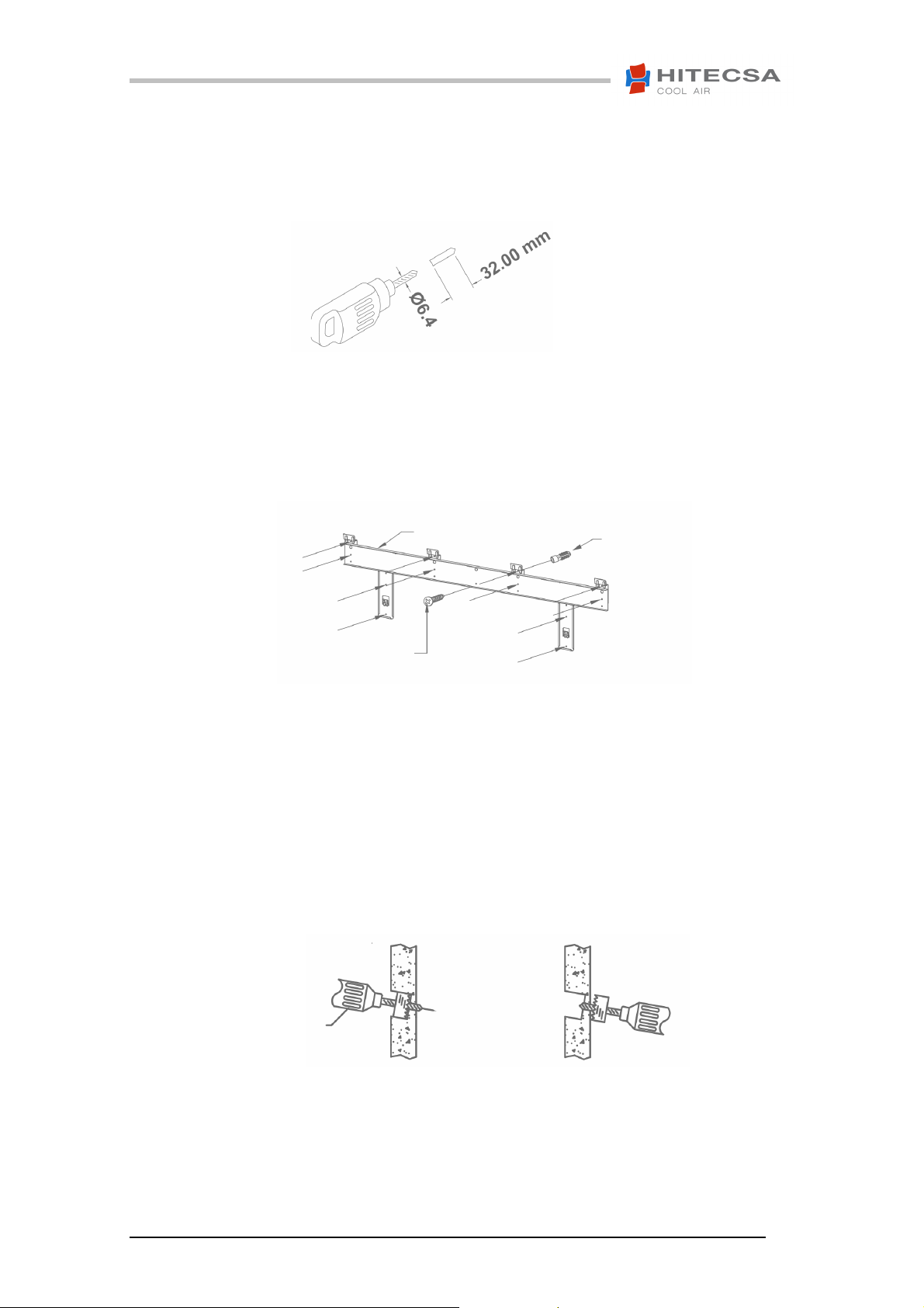
INSTALACIÓN MONTAJE DE PLACA
3. Perforar 6.4 mm de diámetro, 32.0 mm de
profundidad en la pared.
4. Insertar los tacos
5. Fije la placa de montaje y compruebe si
está rígida.
6. Haga un agujero a la tubería de diámetro
70,0 mm, ya sea por la derecha o al lado
izquierdo del fan coil y asegúrese de que
el agujero es ligeramente inclinación hacia
abajo.
7. Si la pared es hueca por favor provea una
manga para el conjunto del tubo para
proteger la línea de drenaje, tuberías y
conexiones de campo.
Interior
Indoor
Tornillo
Screw
Pared
Wall
Placa de montaje
Mounting plate
MOUNTING PLATE INSTALLATION
3. Drill 6.4 mm diameter, 32 mm depht on the
wall.
4. Insert the wall plugs
5. Secure the mounting plate and check for
stiffness.
6. Drill a piping hole 70.0 mm diameter hole
either from the right or to the left fan coil
side and make sure that the hole is slightly
slant downward.
7. If the wall is hollow please provide a
sleeve for tube assembly to protect the
drain line, pipings and field connection.
Pared
Wall
Tacos
Wall Plug
Exterior
Outdoor
04.14 Ref. 200344 Rev. 101
9
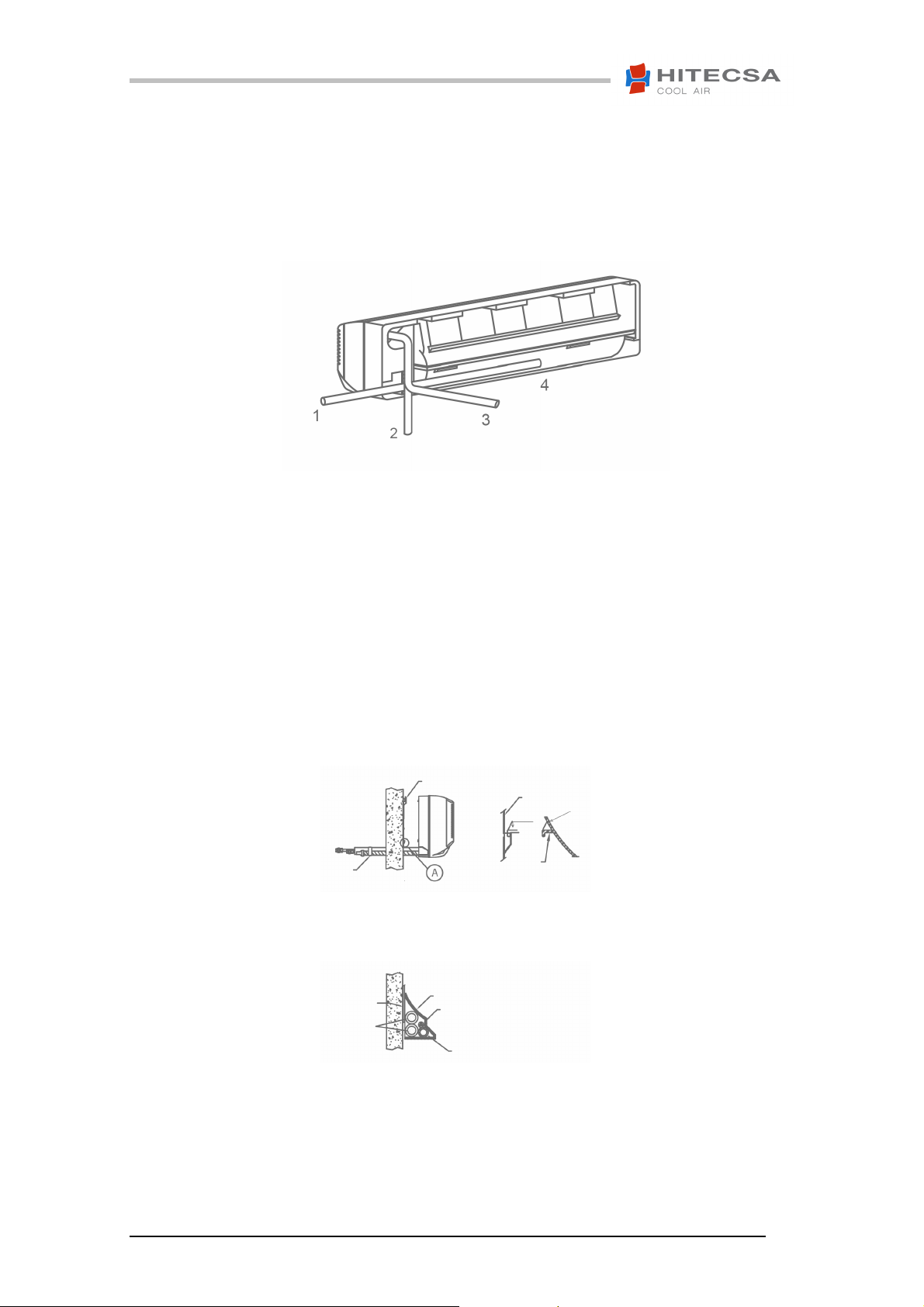
TUBERÍAS Y DRENAJE DE LA UNIDAD
FANCOIL
1. Dirija la tubería fan coil con manguera de drenaje
al agujero. Hay cuatro rutas de tubos posibles.
Por la ruta 1, 2 y 4 cortar la placa para pasar la
tubería a través de él, retire el borde afilado a la
izquierda en la bandeja de la base.
2. Inserte las tuberías y el conducto de drenaje de
la unidad fan coil a través del agujero.
3. Tape la tubería, tubo de desagüe, y el cable de
conexión.
4. Para la tubería horizontal, asegúrese de que se
establecen a lo largo de la ranura en la parte
posterior de la unidad y asegurar la tubería
utilizando la abrazadera de tubería (2 piezas)
antes de fijar la placa de montaje.
5. Asegure la unidad a la placa de montaje.
Lado derecho
Right side
Bajo
Down
PIPING AND DRAINAGE OF FANCOIL
UNIT
1. Route the fan coil tubing with drain hose to the
hole. There are four possible tubing routes. For
the route 1, 2 and 4 cut the plate to pass the pipe
through it, remove sharp edge left on the base
pan.
Lado izquierdo
Left side
Parte trasera
Rear
2. Insert the fan coil unit pipings and drain pipe
through the hole.
3. Tape the tubing, drain hose, and connecting
cable.
4. For the horizontal piping, make sure they are laid
along the groove at the back of unit and secure
the piping using piping clamp (2 pieces) before
fixing to mounting plate.
5. Secure the unit to the mounting plate.
Placa de montaje
Mounting plate
Cinta adhesiva
Scotch tape
Pared
Wall
Placa de montaje
Mounting plate
Tuberías de agua
Water piping
Pared
Wall
Nota: poner la manguera de drenaje como se muestra arriba
Note: Lay the drain hose as shown above
Placa de montaje
Mounting plate
Gancho inferior
Lower hook
Parte de atrás
Back side of the unit
Cable eléctrico
Electric cable
Manguera de drenaje
Drain Hose
Base
Base
DETALLE A
DETAIL A
04.14 Ref. 200344 Rev. 101
10
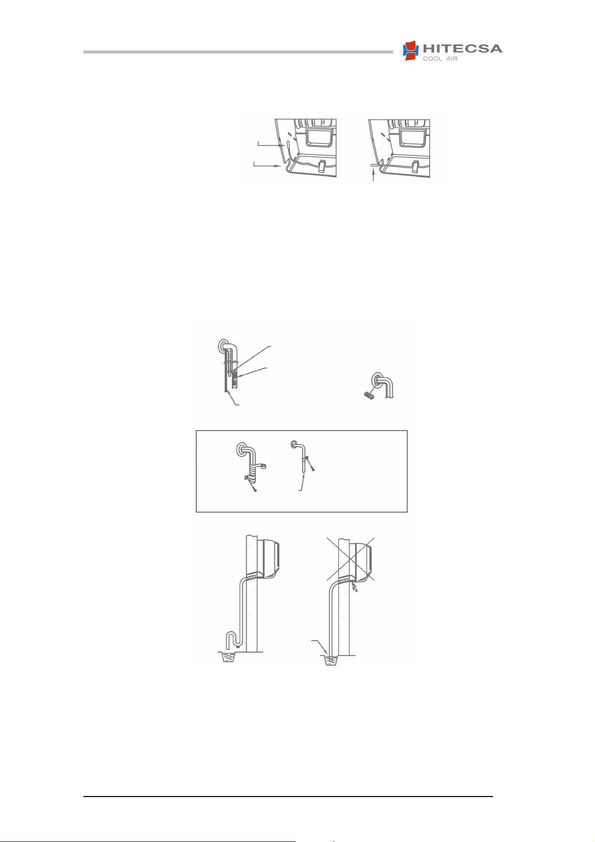
Draw out the room sensor bulb into knockout U
-
hole provision
TUBERÍAS Y DRENAJE DE LA UNIDAD
FANCOIL
Extraiga el sensor de ambiente en la prestación agujero ciego “U”
6. Conecte las tuberías y asegúrese de que las
juntas están instaladas perfectamente.
7. Conecte la manguera de drenaje y póngala sobre
las piezas de conexión.
8. Asegúrese de que el tubo de escape no está
obstruido o tiene depresiones que impiden el
flujo de agua.
ATENCIÓN!
PARA LA INSTALACIÓN DE LAS VÁLVULAS DE
CIERRE / EQUILIBRIO, DE DOS VÁLVULAS DE
CIERRE O DE LA BOMBA DE DRENAJE DE
CONDENSADO HAY QUE INSTALAR UNA CAJA
PREVISTO PARA SISTEMA DE
CLIMATIZACIÓN.
Bulbo sensor de ambiente
Room sensor bulb
Disposición del agujero “U”
Disposal to the hole “U”
Manguera de drenaje
Drain hose
Junta
Coupling
Cableado de interconexión
Interconnecting wiring
PIPING AND DRAINAGE OF FANCOIL UNIT
Bulbo sensor de ambiente
Room sensor bulb
6. Connect the piping and make sure that the
seals are fitted neatly.
7. Connect the drain hose and tape over the
connecting parts.
8. Ensure that the drain hose has no traps or
dips to impede the water flow.
Manguera de drenaje
Drain hose
Cavidad
Dip
ATENTION!
FOR THE INSTALLATION OF SHUT
OFF/BALANCING VALVES, OF TWO SHUT OFF
VALVES OR OF THE CONDENSATE DRAIN
PUMP IT IS NECESSARY TO INSTALL A BOX
FORESEEN FOR CONDITIONING SYSTEM.
Cubrir adecuadamente las tuberías
Cover adequately the piping
04.14 Ref. 200344 Rev. 101
11
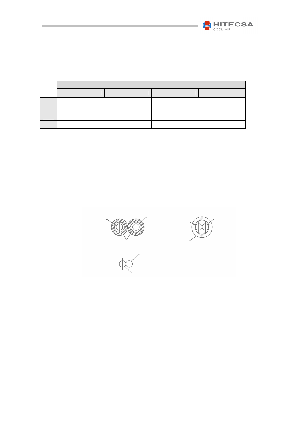
CONEXIÓN DE TUBOS
ATENCIÓN!
Durante la instalación de las tuberías no se
deben crear sifones no deseados.
MOD
20
25
35
40
Entrada agua Water inlet Entrada agua Water inlet
F 1/2" F 1/2"
F 1/2" F 1/2"
F 1/2" F 1/2"
F 1/2" F 1/2"
CONEXIÓN ||||CONNECTION
AISLAMIENTO DE TUBOS
1. El aislamiento de tubos debe cubrirse tanto la
ENTRADA como la SALIDA como se muestra
debajo.
2. Utilice un aislamiento de espuma de polietileno
de 5mm de espesor como mínimo.
Entrada de agua
Water inlet
Aislamiento
Insulation
Salida de agua
Water outlet
Entrada de agua
Water inlet
Salida de agua
Water outlet
PIPING CONNECTION
ATTENTION!
During the installation the piping must not
create undesired siphons.
INSULATION OF PIPES
1. The pipe insulation should cover both INLET and
OUTLET pipes as shown below.
2. Use the insulation of polyethylene foam minimum
of 5 mm in thickness.
Entrada de agua
Water inlet
Aislamiento
Insulation
Salida de agua
Water outlet
04.14 Ref. 200344 Rev. 101
12
 Loading...