

Hitecsa EKWXA 7002.4, EKWXA 8002.4, EKWXBA 7002.4, EKWXA 9002.4, EKWXBA 8002.4 Installation, Operation & Maintenance Manual
...Page 1
Installation, Operation
& Maintena
nce Manual
05.17 207646 Rev.103
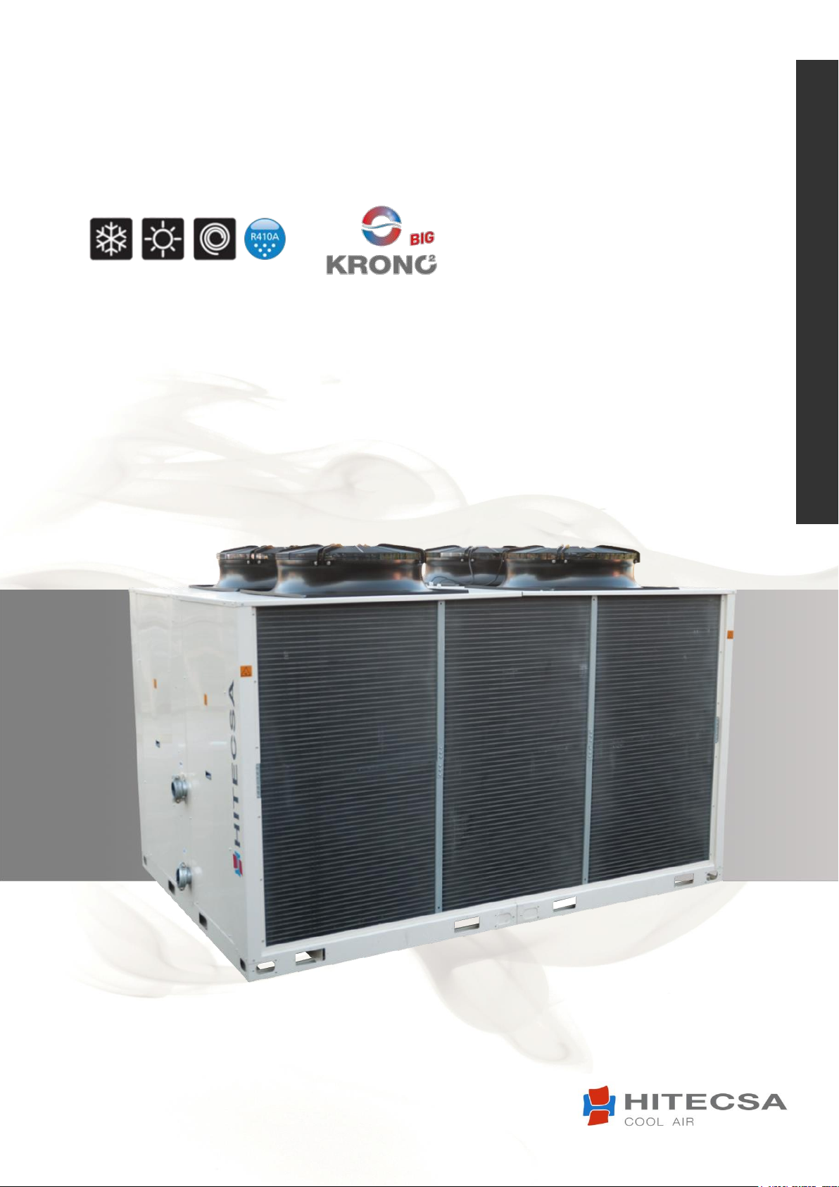
EKWXA │ EKWXBA
AIR-COOLED WATER CHILLERS ─ AXIAL FANS
Models: 7002.4 │ 8002.4 │ 9002.4
Cooling Capacities: from 178,3 kW to 213,6 kW
Heating Capacities: from 194,9 kW to 244,2 kW
ONLY COOLING
HEATING PUMP
Page 2

Thank you for trusting the Hitecsa Products. Our company has been offering the market an extended range of specialized units for
air conditioning and cooling installations for over 35 years. Our approach is based on efficiency, adaptability, usability and practical
solutions. This has been the hallmark of our product catalogue.
The versatility of our factory allows us to contribute solutions, almost tailored to each project’s specifications, in search of a solution
to every problem that arises in design and implementation of air conditioning installations.
From all of us at Hiplus Aire Acondicionado, once again, thank you very much.
Page 3
05.17 207646 Rev.103
EKWXA│EKWXBA
AIR-COOLED WATER CHILLERS
AXIAL FANS
EKWXA – EKWXBA – BIG KRONO II
INDEX
INTRODUCTION ................................................................................................................ 5
CONTENTS ........................................................................................................................... 5
REGULATIONS AND CERTIFICATIONS ................................................................................... 6
SAFETY PRECAUTIONS ...................................................................................................... 6
DESCRIPTION OF THE UNIT ............................................................................................... 7
TECHNICAL DATA ............................................................................................................. 8
RECEPTION ..................................................................................................................... 10
INSPECTION ....................................................................................................................... 10
RIGGING ............................................................................................................................ 10
STORAGE ........................................................................................................................... 10
INSTALLATION ................................................................................................................ 11
DIMENSIONS...................................................................................................................... 11
Model 7002.4 .................................................................................................................. 11
Models 8002.4 │ 9002.4 ................................................................................................. 12
WEIGHT DISTRIBUTION ..................................................................................................... 13
Model 7002.4 .................................................................................................................. 13
Models 8002.4 │ 9002.4 ................................................................................................. 13
INSTALLATION LOCATION .................................................................................................. 14
UNIT SETTLEMENT ............................................................................................................. 14
WATER DRAIN .................................................................................................................... 14
ELECTRICAL CONNECTIONS ............................................................................................... 14
SERVICE AREA .................................................................................................................... 15
Model 7002.4 .................................................................................................................. 15
Models 8002.4 │ 9002.4 ................................................................................................. 15
OPERATION .................................................................................................................... 16
OPERATING LIMITS ............................................................................................................ 16
Modo de Refrigeración 7002.4 │ 5002.4 │ 9002.4.......................................................... 16
Bomba de Calor 7002.4 │ 5002.4 │ 9002.4 ..................................................................... 16
BEFORE START-UP ............................................................................................................. 17
START UP ........................................................................................................................... 17
THERMOSTAT AND CONTROL......................................................................................... 17
MCX-15 CONTROL .............................................................................................................. 17
Main Functions of the Control System ............................................................................ 17
MCX-15 START UP .............................................................................................................. 18
Start Menu ...................................................................................................................... 18
Main Menu ..................................................................................................................... 18
Password Level ............................................................................................................... 19
Inputs/Outputs ............................................................................................................... 19
3
Page 4
05.17 207646 Rev.103
EKWXA│EKWXBA
AIR-COOLED WATER CHILLERS
AXIAL FANS
Model 7002.4 .................................................................................................................. 20
Models 8002.4 │ 9002.4 ................................................................................................. 21
System Parameters ......................................................................................................... 22
Regulation Parameters ................................................................................................... 23
Compressors ................................................................................................................... 23
Alarms ............................................................................................................................. 24
HYDRONIC KIT ................................................................................................................ 26
TECHNICAL DATA ............................................................................................................... 26
OPERATING LIMITS ............................................................................................................ 27
MAINTENANCE ............................................................................................................... 27
CONSERVATION AND CLEANING ....................................................................................... 27
LUBRICANT ........................................................................................................................ 27
REFRIGERANT CHARGE ...................................................................................................... 28
OPTIONAL ...................................................................................................................... 28
ACCESSORIES / OPTIONAL ................................................................................................. 28
APPENDIX: SAFETY DATA R410A .................................................................................... 29
4
Page 5

05.17 207646 Rev.103
EKWXA│EKWXBA
AIR-COOLED WATER CHILLERS
AXIAL FANS
This manual and the instruction documents of refrigeration lines, wiring diagrams and any other attached documents,
have been written to allow a correct installation, set up and maintenance of the unit. Therefore it is essential to read the
instructions with due attention. Verify all the necessary information for the correct installation of the system is included
in the manuals supplied with this unit and / or the rest of the indoor units, accessories, etc. Otherwise, the manufacturer
declines any responsibility for any damage to persons or things, as a result of improper use of the unit and/or failure to
observe these instructions.
Check that electrical network features are in accordance to data shown in the data nameplate of the unit.
The packaging material (plastic bags, insulating materials, nails, etc.) is a potential source of danger and should be kept
out of the reach of children and properly recycled according to local safety regulations. This product should not be mixed
with household waste at the end of its life. Due to the refrigerant, oil and other components contained in this product, it
must be dismantled by professional installers in accordance with current regulations.
Carry out periodic inspections to detect possible damaged or broken pieces. If they are not repaired it could result in
damage to people or stuff. Before executing any maintenance operation, cut off the unit power supply.
All operations must be carried out in accordance with local safety regulations.
Reparations should be always realized for trained personal authorized by the manufacturer using original spares. Failure
to comply with these warnings could affect the safety features of the unit.
INTRODUCTION
CONTENTS
Purpose of the Manual
Preservation Manual
This manual and the electric diagram of the unit must be retained and remain available to the operator for any further consultation.
Updating the Data
The continuous improvement in design and performance to which we are committed gives us the right to modify the specifications of our
products without prior notice.
Electrical Network
Local Safety Regulations
Observe and analyze all possible causes of accidents that may arise in the place or places of installation of the units, check means and
tools to use, etc. It is not possible to anticipate each and every one of the potential circumstances of danger in this manual. Respect the
local security standards during installation.
Principles of Security on Installation
The unit is designed and built in a way that does not pose a risk to the health and safety of people. Appropriate project solutions have
been adopted to eliminate the possible causes of risk in the installation.
Packaging and Replacement of Equipment
Use
The unit will be used only for the reason has been conceived. Any other use does not imply any kind of compromise or link for the
manufacturer.
Incorrect Operation
In case of breakdowns or operation faults, turn off unit.
Periodic Inspections and Maintenance
Repairs
Modifications
All manufacturer responsibility is declined when the warranty has been expired in case of electrical and/or mechanical modifications.
Alterations in general not expressly allowed and not respecting what is instructed here, they cause the warranty expiration.
Refrigerant
This product is hermetically sealed and contains R-410A which is a HFC fluorinated greenhouse gas.
5
Page 6
05.17 207646 Rev.103
EKWXA│EKWXBA
AIR-COOLED WATER CHILLERS
AXIAL FANS
DANGER
ATTENTION!
WARNING!
WARNING!
INTRODUCTION
REGULATIONS AND CERTIFICATIONS
ISO 9001:2008 CERTIFICATION: HILPUS AIRE ACONDICIONADO S.L., trying always to find the customer satisfaction, has obtained
the ISO 9001:2008 Quality System referred to its production activity. This will results in a continuous determination to improve quality and
reliability of all our products; commercial activities, design, raw materials, production and after-sales service, are the means to reach our
goal.
CE MARKING: Our machines have got the CE mark, in conformity with the essential requirements of the applicable EC
directives and their last modifications as well as with the national legislation of each country.
CERTIFICACION EUROVENT: HITECSA participates in the EUROVENT Certification program. Check certified products on the web.
SAFETY PRECAUTIONS
Before starting installation, service or maintenance, turn off the main power switch in order to avoid
electrical shock that may cause personal damages.
To open the electrical panel and access the inside of the machine it is MANDATORY to disconnect the power supply hose from the
machine, it MUST BE FREE OF TENSION for this operation.
Do not touch or adjust the safety elements inside any unit of the system. In the repairs use only original spare parts and install them
properly in the same position where old parts were placed.
Installation and maintenance of air conditioning equipment can be dangerous because the system is under pressure, because some
of its elements have high temperatures and include electrical components.
Do not install the unit in explosive atmosphere.
Only qualified and trained service staff should install, commission and carry out maintenance works. Unqualified staff should only
carry out basic tasks such as cleaning and replacement of filters, etc.
Prevent access to children so they can not play with the appliances.
In every visit, all precautions should be taken into account: those recommended in the Installation, operation and maintenance
instructions, as well as the ones indicated in labels of the unit. Do not forget to strictly follow any other safety codes.
NO objects should be introduced into the air inlets or outlets that can be drawn into the fan, people, etc.
Use safety glasses, work gloves and any other safety accessory necessary.
For brazing operations use a quenching cloth and have at close distance a fire extinguisher.
This product contains fluorinated greenhouse gases, its leakage can cause displacement of air and cause insufficient oxygen to
breathe.
Must follow all safety recommendations.
6
Before starting the equipment, make sure that the water tank is completely full and that the installation
SECURITY OF THE OPTIONAL HYDRONIC KIT WITH ELECTRIC HEATERS.
is perfectly drained of air.
Page 7
05.17 207646 Rev.103
EKWXA│EKWXBA
AIR-COOLED WATER CHILLERS
AXIAL FANS
DESCRIPTION OF THE UNIT
The EKWXA / EKWXBA units are compact reversible WATER / AIR units for the production of hot / cold water. They are designed for
outdoor installation. Supplied with R-410A refrigerant charge, ready for installation.
These units are manufactured under a strict quality control throughout their process and once finished are tested in the factory, verifying
the correct operation of all its components.
The unit is composed by:
Hermetic compressor, alternative, with wide operating limits. It incorporates thermal protection of the windings (without requiring
additional protection), the oil load for its perfect lubrication and internal damping system. The compressor is mounted on the chassis
with shock absorbers and is acoustically insulated. All this guarantees a silent operation and without vibration.
External coils built with copper tube without welds and expanded in aluminum fins. Incorporate distributor with neck and calibrated
orifice (nozzle) to improve distribution of the gas in Cold mode.
Coolant-water exchanger made from stainless steel plates (AISI 316) welded with bronze base. It is perfectly insulated with insulating
heat material to prevent the exchange of heat with the outside. It has built-in electrical heaters as an anti-ice protection to avoid the
risks of breaking it by freezing the water in case of lack of flow.
Fan motor mounted with a square base and circular inlet embouchure suitable for the aerodynamic performance of the flow driven
by the fan itself. Ready for outdoor installation, totally closed, with permanent lubrication. It consists of aluminum blades designed
to obtain a low sound level, inserted into the outer rotor of a high efficiency motor, with IP-54 protection and class F winding
insulation. It has internal thermal probes incorporated for its protection, as well as external security grid.
Thermostatic expansion valve with MOP at the plate exchanger inlet for cooling mode operation. The expansion in the external coil,
when necessary (operation in heating mode), is realized through a hole.
Safety pressure switch connected to the compressor output (maximum pressure point) of manual reset. Its cut is calibrated at a
pressure of 42 bars.
Bidirectional dehydrator filter type mounted on the liquid line. It consists of a solid desiccant core that minimizes vibration and friction
during the operation of the equipment besides absorbing excess moisture and filter any impurities.
Tank to contain the variations of the refrigerant charge required by the machine when changing its operation between Cool/Heat.
Check valves only on Heat Pump units to bypass the expansion system of the secondary exchanger block. Cold mode performs the
bypass to battery, in Heat mode, it is done to the expansion valve.
The sheet metal structure of these equipments is resistant to the weather and is formed by galvanized steel sheet which is applied
an oven painting process by polymerization of powder paint which provides excellent overall coating and especially in corners and
edges. The self-supporting base is constructed with highly rigid steel. The rest of the structure is galvanized steel. The design is
done for an easy maintenance. The finished set has RAL 1013 color.
7
Page 8
05.17 207646 Rev.103
EKWXA│EKWXBA
AIR-COOLED WATER CHILLERS
AXIAL FANS
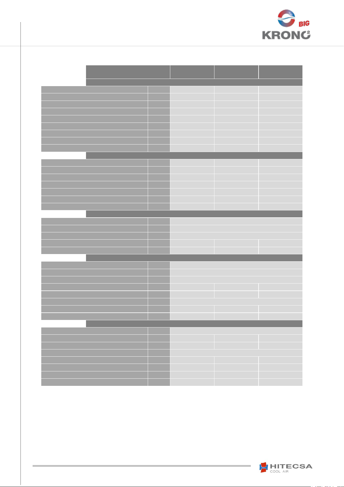
EKWXA/EKWXBA
7002.4
8002.4
9002.4
COOLING MODE
(1)
Cooling capacity
kW
178,3
200,1
213,6
Total absorbed capacity
(3)
kW
61,3
73,8
81,8
Total rated current
A
107,7
123,6
138,2
Compressor absorbed power
kW
54,2
65
72,8
Compressor rated current
A
94,3
111,8
125,2
Evaporator water flow
m³/h
33
35,5
37
Evaporator pressure drop
kPa
63
70,8
77,5
EER
2,91
2,71
2,61
ESEER
- -
-
HEATING MODE
(2)
Cooling capacity
kW
194,9
224,3
244,2
Total absorbed capacity
(3)
kW
60,7
74,5
86,9
Total rated current
A
112,1
129,1
142,4
Compressor absorbed power
kW
56,7
65,8
73,2
Compressor rated current
A
98,1
112,1
125,6
COP
3,21
3,01
2,81
SCOP
- -
-
REFRIGERANT
Number of circuits
2
Type
R-410A
Global warming potential (GWP)
(4)
2088
Refrigerant charge cooling only (no optional)
Kg
2 x 23
2 x 22
2 x 23
Refrigerant charge heating pump (no optional)
Kg
2 x 23
2 x 23.5
2 x 24
COMPRESSOR
Type
SCROLL
Number of compressors
4
Number of power stages
4
Maximum current for operating circuit
A
71
80
89
Locked rotor current
A
249
264
309
Oil type
POE 160 SZ
Oil volume
L
2 x (6,7 + 6,7)
2 x (6,7 + 6,7)
2 x (6,7 + 6,7)
Crankcase strength
W
2 x (75 + 75)
2 x (75 + 75)
2 x (75 + 75)
FANS
Type
AXIAL
Number of total fans
4 6
6
Rated air flow
m3/ h
91690
105398
105398
Available static pressure
Pa
0
Diameter
mm
800
710
710
Absorbed power (by fan)
kW
2,06 / 1,33
1,52/ 0,97
1,52/ 0,97
Rated current (by fan)
A
3,8 3 3
Speed
r.p.m.
910
914
914
TECHNICAL DATA
Note:
(1) COOLING MODE: Outdoor temperatura 35ºC, Water inlet temperature 12ºC, Water outlet temperature 7ºC.
(2) HEATING MODE: Outdoor temperature 7ºC D.B. / 6ºC W.B., Inlet temperature 40ºC, Water outlet temperature 45ºC.
(3) TOTAL ABSORBED CAPACITY: Absorbed power by the equipment in Cold or Heat conditions indicated above according to UNE-EN-14511-2: 2013.
(4) GWP: Global warming potential (climatic) of 1 kg of greenhouse gas relative to 1 kg of CO2, calculated in terms of 100-year warming potential.
(5) Measurement conditions on the free field, directivity 2 and 1,5 meters above the floor.
8
Page 9
05.17 207646 Rev.103
EKWXA│EKWXBA
AIR-COOLED WATER CHILLERS
AXIAL FANS
EKWXA/EKWXBA
7002.4
8002.4
9002.4
OUTDOOR HEAT EXCHANGER
Type
Aluminum fin coil and copper tubing
Quantity
2
Front surface of the exchanger
m2
5,18 + 5,18
INDOOR HEAT EXCHANGER
Type
PLATES (Water / Refrigerant)
Quantity
2
Evaporator water flow
m3/ h
33
35,5
37
Evaporator pressure drop
KPa
63
70,8
77,5
Water volume
L
8,4
8,4
8,4
Anti-ice resistance
W
100
WATER CONNECTIONS
Type
SLOTTED – Victaulic type
External diameter
(‘’)
3 ''
3 ''
3 ''
ELECTRIC SPECIFICATIONS
Supply voltage
V / ~F / Hz
400V - 3+N 50Hz
Maximum intensity
A
156,2
178,2
196,6
Starting current (AC)
A
334,7
362,1
416,3
SOUND LEVEL
Sound power
dB(A)
92,8
94,7
94,8
Sound pressure (5m)
(5)
dB(A)
71
72,9
73
WEIGHT AND DIMENSIONS
Large
mm
3200
Width
mm
2250
High
mm
2150
Net weight of heat pump units - EKWXBA
kg
1720
1753
1759
Net weight of cooling only units - EKWXA
kg
1686
1719
1725
TECHNICAL DATA
Note:
(1) COOLING MODE: Outdoor temperatura 35ºC, Water inlet temperature 12ºC, Water outlet temperature 7ºC.
(2) HEATING MODE: Outdoor temperature 7ºC D.B. / 6ºC W.B., Inlet temperature 40ºC, Water outlet temperature 45ºC.
(3) TOTAL ABSORBED CAPACITY: Absorbed power by the equipment in Cold or Heat conditions indicated above according to UNE-EN-14511-2: 2013.
(4) GWP: Global warming potential (climatic) of 1 kg of greenhouse gas relative to 1 kg of CO2, calculated in terms of 100-year warming potential.
(5) Measurement conditions on the free field, directivity 2 and 1,5 meters above the floor.
9
Page 10
05.17 207646 Rev.103
EKWXA│EKWXBA
AIR-COOLED WATER CHILLERS
AXIAL FANS
RECEPTION
INSPECTION
At the time of equipment delivery it is advisable to examine it carefully.
Check that the equipment has not been damaged during transport and has been supplied complete with all parts specified in the
order and/or with the optionals specified in the order. If this is not the case contact the transport company immediately. (First 48h).
Verify the correct voltage of the nameplate and make sure it’s in accordance with local power supply.
In case of any flaw or anomaly detected, please contact HITECSA.
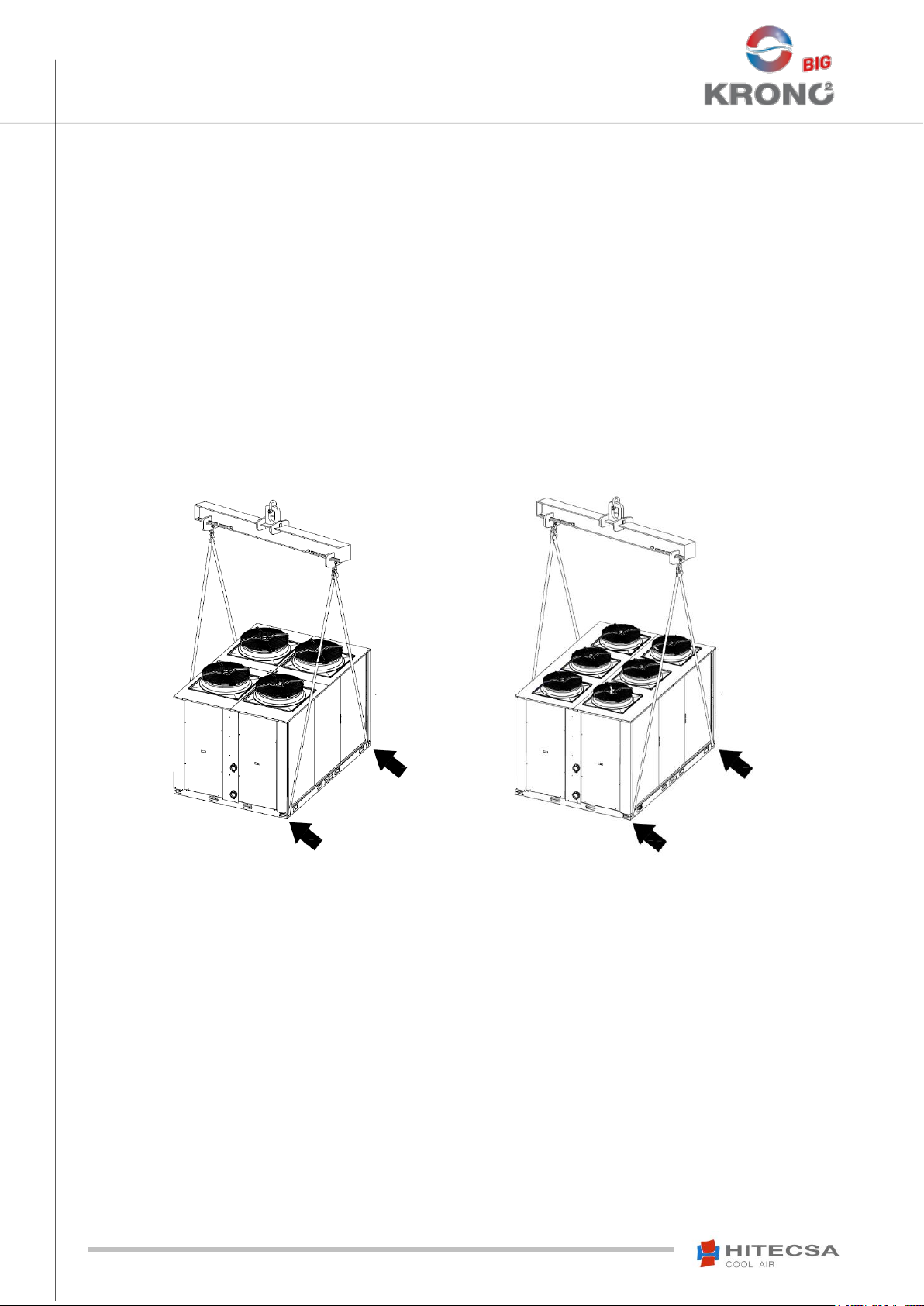
RIGGING
Before moving the unit, make sure that all panels are well fixed.
Raise and set down the equipment carefully.
Do not tilt the unit more than 15 degrees during transportation.
When lifting the unit, make sure that it’s balanced and stable; bear in mind that the heaviest part is where the compressor is installed.
Always transport the unit in its original packaging to the place of installation.
Lifting through crane.
STORAGE
If the equipment is going to be stored please follow the instructions below in order to avoid damages, corrosion or deterioration:
Do not place the machine in places exposed to ambient temperature above 50ºC and preferably keep the unit away from direct
sunlight.
Avoid prolonged storage, before installation, water inlet, dust and objects in general due to invasion or biological, meteorological
and/or human inclemencies.
Minimum storage temperature is 5ºC.
Maximum Relative Humidity: 90%.
It is also recommended:
10
Move it carefully.
Avoid placing other objects on top of the unit (unless it is done within the limits of the overlap planes indicated on the packaging).
Avoid placing the unit with heat-shrink protection under the sun, as the pressure of the circuits could assume values that could lead
to the intervention of the safety valves.
Page 11

05.17 207646 Rev.103
EKWXA│EKWXBA
AIR-COOLED WATER CHILLERS
AXIAL FANS
1. Water inler Ø 3”
INSTALLATION
DIMENSIONS
Model 7002.4
2. Water outlet Ø 3”
3. Electrical panel
4. Main switch
5. Electrical connection input
6. Optional electrical connection input
7. Water inlet with Hydronic Kit Ø 3”
11
Page 12

05.17 207646 Rev.103
EKWXA│EKWXBA
AIR-COOLED WATER CHILLERS
AXIAL FANS
1. Water inler Ø 3”
INSTALLATION
DIMENSIONS
Models 8002.4 │ 9002.4
2. Water outlet Ø 3”
3. Electrical panel
4. Main switch
5. Electrical connection input
6. Optional electrical connection input
7. Water inlet with Hydronic Kit Ø 3”
12
Page 13

05.17 207646 Rev.103
EKWXA│EKWXBA
AIR-COOLED WATER CHILLERS
AXIAL FANS
WEIGHT DISTRIBUTION (kg)
R1
R2
R3
R4
R5
R6
R7
R8
TOTAL
7002.4
Heating
pump
233
246
194
181
185
187
248
246
1720
Cooling
only
234
247
181
173
176
184
244
247
1686
WEIGHT DISTRIBUTION (kg)
R1
R2
R3
R4
R5
R6
R7
R8
TOTAL
8002.4
Heating
pump
229
241
206
185
189
195
249
259
1753
Cooling
only
228
241
195
178
181
192
244
259
1719
9002.4
Heating
pump
229
242
206
185
189
196
250
262
1759
Cooling
only
229
242
195
178
181
193
246
262
1725
INSTALLATION
WEIGHT DISTRIBUTION
Model 7002.4
Models 8002.4 │ 9002.4
13
Page 14

05.17 207646 Rev.103
EKWXA│EKWXBA
AIR-COOLED WATER CHILLERS
AXIAL FANS
WARNING!
Recommended siphon measures
INSTALLATION
INSTALLATION LOCATION
Consult and respect the rules and local regulations which regulate the installation of air conditioning systems.
Choose a site without dust and debris.
Respect the appropriate service area for the equipment wich will be installed.
Verify that the ground or structure on which the unit will be installed is able to support its weight in operation.
Fit shock absorbers throughout the installation to prevent the transmission of noise and vibration.
Check that the direction of the sound level is not going to disturb anyone.
UNIT SETTLEMENT
Be sure unit is correctly leveled.
The bed frame should have sufficient strength to support unit weight.
Be sure that after settlement the unit drain is working properly.
WATER DRAIN
The indoor drain (of condensate water) has connection 3/4’’ MPT.
Condensate evacuation line diameter should be equal or larger than unit drain
connection depending on the line length and general building configuration.
The condensate line should be pitched a minimum 2% for proper water evacuation.
When drain line is exposed to air temperatures below 0 grades is necessary to provide
thermal insulation or electrical heating wire to avoid water freezing and tube damage.
It is convenient to install the trap with proper dimensions.
ELECTRICAL CONNECTIONS
Before starting any type of operations put in position off main power switch.
Unit current supply should be within 10% of Volts indicated on the unit nameplate.
Unit star-up at incorrect voltage and resulted from its damages are not covered by Hitecsa guarantee.
When making electrical connections always use the unit wiring diagram.
Be sure that the compressor crankcase heater can be energized before unit start.
Do not operate at any different current from that is shown on the unit’s nameplate.
The installer has to install the line protection elements according to the local laws.
The interconnecting wires have to be in the protection tube or inside the groove channel.
14
Page 15

05.17 207646 Rev.103
EKWXA│EKWXBA
AIR-COOLED WATER CHILLERS
AXIAL FANS
INSTALLATION
SERVICE AREA
Be sure to respect the measures for a proper operation of the unit.
Model 7002.4
Models 8002.4 │ 9002.4
15
Page 16

05.17 207646 Rev.103
EKWXA│EKWXBA
AIR-COOLED WATER CHILLERS
AXIAL FANS
OPERATING LIMITS
7002.4
8002.4
9002.4
Nominal Water Flow
m3/h
33
35,5
37
Minimum Water Flow
m3/h
21,9
23,6
24,6
Maximum Water Flow
m3/h
49,5
53,3
55,5
Minimum Volume of Water
l
455
510
550
EKWXA - EKWXBA
6025 30 35 40
45
50
55
-15
-10
-5
0
5
10
15
20
LWT (°C)
Temperatura exterior / Outdoor temperature / Témperature éxterieur (°C)
-7
-10
-5
0
5
10 15 20 25
-20
-10
0
10
20
30
40
55
LWT (°C)
Temperatura exterior / Outdoor temperature / Témperature éxterieur (°C)
25
46
-20
-10
-5
0
5
-15
-10
0
10
20
30
40
46
LWT (°C)
Temperatura exterior / Outdoor temperature / Témperature éxterieur (°C)
55
18
-7
EKWXA - EKWXBA
+ Glicol
+ Glycol
EKWXA - EKWXBA
+ Control de condensación
+ Condensation Control
+ Contrôle de la Condensation
EKWXA - EKWXBA
EKWXA - EKWXBA
+ Glicol
+ Glycol
-15
OPERATION
OPERATING LIMITS
Modo de Refrigeración 7002.4 │ 5002.4 │ 9002.4
Bomba de Calor 7002.4 │ 5002.4 │ 9002.4
16
Page 17

05.17 207646 Rev.103
EKWXA│EKWXBA
AIR-COOLED WATER CHILLERS
AXIAL FANS
Check the following points:
BEFORE START-UP
OPERATION
Electrical connections are well tightened.
Panels are firmly secured with screws.
There are no oil or refrigerant leaks.
The unit is correctly leveled.
There is enough space for service and maintenance.
Drainage is not blocked.
Check that the crankcase heater of each compressor is in operation for 24 hours prior to commissioning.
Air filters are cleaned and correctly mounted.
Grilles, air diffusers, air ducts and flexible connections are in good condition.
Electrical power source is in accordance with what is said in the nameplate.
Fans rotate in the right direction.
START UP
Start up has to be performed by a qualified service person.
It is necessary to take notes of the air inlet and outlet temperatures to the internal coil, the volts and amps of the compressor and
motor fan, as well as the suction and discharge pressure of each compressor.
It should be remembered that it is necessary to clean the air filters after the first 4 hours of operation.
Observe at least, 3 cooling cycle operations.
Due to the unit equips frequency converters, it is essential that the power is at least 300mA to prevent power cuts caused by the
activation of the circuit breaker.
THERMOSTAT AND CONTROL
MCX-15 CONTROL
The control is composed of a user interface and an electronic board.
Power supply 20/30 Vdc – 24 Vac.
Panel mounting type.
Screen with display that allows the inputs and outputs to be visualized.
Operating mode: 4 compressors, cooling only and heat pump.
Defrosting by pressure transducers.
Management of water circulating pump and hydraulic module.
Clock programming.
Programmable controller with 3 access levels: User, Maintenance and
Manufacturer.
Main Functions of the Control System
Regulates water temperature.
Service hour counter for compressors and water pumps
(optional).
Intake and outlet water temperature reading displays, as well
as, pressure reading displays in evaporator and condenser
stages.
Compressor start timers.
Pressure overload safety protection.
Electronic compressor protection.
External fan protection.
Water flow protection.
Anti-freeze active protection.
Remote ON/OFF.
Remote COOL/HEAT mode toggle
Condensing and evaporating pressure control by incorporating
2 ventilation stages
Check valve for cycle reversion (only available for Heat Pump
units)
Anti-frost feature. Anti-frost start and stop settings through
pressure readings.
Anti-frost duration time control.
17
Page 18

05.17 207646 Rev.103
EKWXA│EKWXBA
AIR-COOLED WATER CHILLERS
AXIAL FANS
(UP) By pressing and holding this key for, at least, 3 seconds the unit will start up if it was shutdown or it shuts down
if it is running.
(DOWN) By pressing and holding this key, at least, 3 seconds the unit will toggle between cooling and heating mode.
If the unit is running, it needs to stop prior to switching modes and then it must be started up once again.
(ESC) Pressing this key leads to a shortcut to the ALARMS menu.
(RETURN) This key takes the user to the MAIN MENU screen if it is pressed in the START MENU screen. It is also
used to enter menus for other selected options.
(UP) Used to scroll UP between highlighted options.
(DOWN) Used to scroll DOWN between highlighted options.
(ESC) Returns to the previous screen of a highlighted
option.
(RETURN) Advances to the next screen or sublevel of a
highlighted option.
THERMOSTAT AND CONTROL
MCX-15 START UP
Start Menu
Keypad utility
Main Menu
Keypad utility
ON
Starts up the unit using the last settings.
OFF
Shuts off the unit according to the established time parameters.
HEAT/COOL
Toggles between operating modes.
18
Page 19

05.17 207646 Rev.103
EKWXA│EKWXBA
AIR-COOLED WATER CHILLERS
AXIAL FANS
DISPLAY “A” DISPLAY “B” ALARMS/WARNINGS
COMPRE
SSOR
WATER PUMP
OUTDOOR FAN
ANTI-FREEZE HEATER
COOL/HEAT/ ANTI
- FROST MODE
DIGITAL OUTPUTS
1=ON
ANALOG
OUTPUTS
DIGITAL INPUTS
1= Acti
ve
ANALOG INPUTS
THERMOSTAT AND CONTROL
MCX-15 START UP
Password Level
There are 3 clearance levels for different parameters or system setting options.
Level L0: User Access, no password required.
Level L1: User-Maintenance Access.
Level L2: Manufacturer authorized Access ONLY.
Inputs/Outputs
0=No Active
0=OFF
19
Page 20

05.17 207646 Rev.103
EKWXA│EKWXBA
AIR-COOLED WATER CHILLERS
AXIAL FANS
POSITION
ANALOG INPUTS
DIGITAL INPUTS
ANALOG OUTPUTS
DIGITAL OUTPUTS
1
Water inlet temperature
Differential pressure
switch/ Flow switch
Fans circuit 1
Compressor 1 circ.1
2
Water outlet temperature
circuit 1
Thermal Compressor 1
Fans circuit 2
Compressor 2 circ.1
3
Water outlet temperature
circuit 2
Thermal Compressor 2
4 ways valve, circuit 1 (only
heat pump)
4
Cond./evap pressure.
Cool/Heat circuit 1
Thermal outdoor fans
circuit 1
Antifreeze resistance circuit
1
5
Evap./cond pressure.
Cool/Heat circuit 1
Safety high pressure
switch circuit 1
Compressor 1 circ.2
6
Cond./evap pressure.
Cool/Heat circuit 2
Remote Start/Stop
Compressor 2 circ.2
7
Evap./cond pressure.
Cool/Heat circuit 2
Remote Cool/Heat selector
Water pump (KIT 1 pump)
8
Second SETPOINT
Antifreeze resistance circuit
2
9
Thermal Compressor 3
10
Thermal Compressor 4
11
Thermal outdoor fans
circuit 2
Fans circuit 1
12
Safety high pressure
switch circuit 2
Fans circuit 2
13
Thermal pump
14
4 ways valve, circuit 2 (only
heat pump)
15
THERMOSTAT AND CONTROL
MCX-15 START UP
Model 7002.4
20
Page 21

05.17 207646 Rev.103
EKWXA│EKWXBA
AIR-COOLED WATER CHILLERS
AXIAL FANS
POSITION
ANALOG INPUTS
DIGITAL INPUTS
ANALOG OUTPUTS
DIGITAL OUTPUTS
1
Water inlet temperature
Differential pressure
switch/ Flow switch
Fans circuit 1
Compressor 1 circ.1
2
Water outlet temperature
circuit 1
Thermal Compressor 1
Fans circuit 2
Compressor 2 circ.1
3
Cond./evap pressure.
Cool/Heat circuit 1
Thermal Compressor 2
4 ways valve, circuit 1 (only
heat pump)
4
Evap./cond pressure.
Cool/Heat circuit 1
Thermal outdoor fans
circuit 1
Antifreeze resistance circuit
1
5
Cond./evap pressure.
Cool/Heat circuit 2
Safety high pressure
switch circuit 1
Compressor 1 circ.2
6
Evap./cond pressure.
Cool/Heat circuit 2
Remote Start/Stop
Compressor 2 circ.2
7
Water outlet temperature
circuit 2
Remote Cool/Heat selector
4 ways valve, circuit 2 (only
heat pump)
8
Second SETPOINT
Antifreeze resistance circuit
2
9
Thermal Compressor 3
10
Thermal Compressor 4
11
Thermal outdoor fans
circuit 2
Fans circuit 1
12
Safety high pressure
switch circuit 2
Fans circuit 2
13
Thermal pump
14
Water pump (KIT 1 pump)
15
THERMOSTAT AND CONTROL
MCX-15 START UP
Models 8002.4 │ 9002.4
21
Page 22

05.17 207646 Rev.103
EKWXA│EKWXBA
AIR-COOLED WATER CHILLERS
AXIAL FANS
OFF: No reading shown.
IdOF: ON/OFF state.
Set: Set point value for current operating mode.
reg: (Varies according to the model of the unit)
AI1: Intake water temperature. (Default setting)
AI2: Outlet water temperature.
OFF: No reading shown.
IdOF: ON/OFF state.
Set: Set point value for current operating mode. (Default setting)
reg: (Varies according to the model of the unit)
AI1: Intake water temperature.
AI2: Outlet water temperature
OFF: The unit is set to Standby or OFF mode.
ON: The unit starts up.
EQUA: The unit resumes operation under the same settings as the last
time it was running before loss of power.
THERMOSTAT AND CONTROL
MCX-15 START UP
System Parameters
Display Screens
Display screen “A”.
Select the Reading to be shown in Display screen A when the unit is running. By default, the reading shown on Display screen A when
the unit is shut down is “OFF”.
Display screen “B”.
Select the Reading to be shown in Display screen B when the unit is running.
Password
Displays Installer-Maintenance password.
Setup
System ON/OFF.
Indicates whether the unit is running (ON) or if it is shutdown (OFF), it also allows starting up or shutting down the unit by selecting
ON/OFF.
Restart After Disconnection Mode.
Following a sudden power outage, this indicates the operational mode for restart.
System HEAT / COOL
Indicates current operating mode HEAT/COOL and, it also allows switching between modes.
If the unit is running, it stops before switching operating modes and then it is started up in the new mode.
Scheduler enable.
Enables/Disables Programming Mode.
22
Page 23

05.17 207646 Rev.103
EKWXA│EKWXBA
AIR-COOLED WATER CHILLERS
AXIAL FANS
AI1: Regulation of INTAKE water.
AI2: Regulation of OUTLET water.
THERMOSTAT AND CONTROL
MCX-15 START UP
Regulation Parameters
Configuration
Temperature Regulation Entry
This is used to tell the system whether regulation will be applied to IN or OUT water temperature.
Calibration of the Regulation Probes.
Adjusts probe regulation values in the range between -99,9 and 99,9.
Set Point
Cooling Set point Temperature.
Sets the value of the operating Cooling Set point temperature in ºC, by default this value is set to 7ºC. Values can range between 6,0
and up to 17,0ºC.
Lower Limit Set point Temperature.
This is used to set the lowest limit of the Set point temperature in cooling more.
By default this value is 6,0ºC.
High Limit Set point Temperature.
This is used to set the highest limit of the Set point temperature in cooling more.
By default this value is 17,0ºC.
Heating Set point Temperature.
Sets the value of the operating Cooling Set point temperature in ºC, by default this value is set to 45ºC. Values can range between
35,0 and up to 55,0ºC.
Lower Limit Set point Temperature.
This is used to set the lowest limit of the Set point temperature in heating more.
By default this value is 35,0ºC.
High Limit Set point Temperature.
This is used to set the highest limit of the Set point temperature in heating more.
By default this value is 55,0ºC.
Compressors
Activation
Activation of compressor 1
Activates or disables compressor 1.
Activation of compressor 2
Activates or disables compressor 2.
23
Page 24

05.17 207646 Rev.103
EKWXA│EKWXBA
AIR-COOLED WATER CHILLERS
AXIAL FANS
CODE
DESCRIPTION
RESET
TYPE
COMPRESSOR
WATER
PUMP
CONDENSER
FAN
ANTIFREEZE
HEATER
A03
Evaporator flow switch
Manual
OFF
OFF
OFF
OFF
A09
High temperature
Notification
- - -
-
A10
Evaporator pump service time limits
exceeded
Notification
- - -
-
A11
Evaporator pump 2 service time
limits exceeded
Notification
- - -
-
A12
Condenser fan service time limits
exceeded
Notification
- - -
-
A13
Maximum time of defrost exceeded
Notification
- - -
-
A50
General fan thermal protection
Automatic
OFF - OFF
-
A61
Maximum service hours for
compressor 1 exceeded
Notification
- - -
-
A62
Maximum service hours for
compressor 2 exceeded
Notification
- - -
-
A63
Service Hours For Compressor 3
Exceeded
Notification
- - -
-
A64
Service Hours For Compressor 4
Exceeded
Notification
- - -
-
A7A
Intake water probe
Automatic
OFF
OFF
OFF
OFF
A7B
Outlet Water Probe Circuit 1
Automatic
OFF C1
OFF
OFF
OFF
A7C
Outlet Water Probe Circuit 2
Automatic
OFF C2 - -
-
A7G
Discharge Transducer Probe Circuit
1
Automatic
OFF C1
OFF
OFF
OFF
A7H
Discharge Transducer Probe Circuit
2
Automatic
OFF C2 - -
-
A7V
Intake Transducer Probe Circuit 1
Automatic
OFF C1
OFF
OFF
OFF
A7W
Intake Transducer Probe Circuit 2
Automatic
OFF C2 - -
-
AC0
General Thermal Compressor Alarm
Manual
OFF - -
-
AC1
Thermal compressor 1 circuit 1
Manual
OFF - -
-
AC2
Thermal compressor 2 circuit 1
Manual
OFF - -
-
AC3
Thermal compressor 1 circuit 2
Manual
OFF - -
-
AC4
Thermal compressor 2 circuit 2
Manual
OFF - -
-
AE1
Anti-freeze circuit 1
Manual
OFF C1
ON - -
AE2
Anti-freeze circuit 2
Manual
OFF C2
ON - -
THERMOSTAT AND CONTROL
MCX-15 START UP
Alarms
24
Page 25

05.17 207646 Rev.103
EKWXA│EKWXBA
AIR-COOLED WATER CHILLERS
AXIAL FANS
CODE
DESCRIPTION
RESET
TYPE
COMPRESSOR
WATER
PUMP
CONDENSER
FAN
ANTIFREEZE
HEATER
AF1
Thermal Protection Fan Circuit 1
Manual
OFF C1
-
OFF C1
-
AF2
Thermal Protection Fan Circuit 2
Manual
OFF C2
-
OFF C2
-
AH0
General High Pressure
Manual
OFF - -
-
AH1
High Pressure Circuit 1
Manual
OFF C1 - -
-
AH2
High Pressure Circuit 2
Manual
OFF C2 - -
-
AL0
General low water pressure
protection
Manual
OFF - -
-
AL1
Low Pressure Protection Circuit 1
3 times in 1
hour
OFF C1 - -
-
AL2
Low Pressure Protection Circuit 2
3 times in 1
hour
OFF C2 - -
-
AP0
General Evaporator Pump
Manual
OFF
OFF
OFF
OFF
AP1
Thermal protection water pump 1
Automatic
-
OFF - -
AP2
Thermal protection water pump 2
Automatic
-
OFF - -
AP9
Operation reserved pump
Notification
- - -
-
E10
EEV Connection Alarm Circuit 1
Manual
OFF C1 - -
-
E12
EEV Reheat Temperature Alarm
Circuit 1
Manual
OFF C1 - -
-
E14
EEV Evaporation Pressure Alarm
Circuit 1
Manual
OFF C1 - -
-
E16
EEV Refrigerant Not Selected Alarm
Circuit 1
Manual
OFF C1 - -
-
E17
EEV Valve Operation Alarm Circuit 1
Manual
OFF C1 - -
-
E18
EEV Low Battery Alarm Circuit 1
Manual
OFF C1 - -
-
E19
CAN EEV Communication Alarm
Circuit 1
Manual
OFF C1 - -
-
E20
EEV Connection Alarm Circuit 2
Manual
OFF C2 - -
-
E22
EEV Reheat Temperature Alarm
Circuit 2
Manual
OFF C2 - -
-
E24
EEV Evaporation Pressure Alarm
Circuit 2
Manual
OFF C2 - -
-
E26
EEV Refrigerant Not Selected Alarm
Circuit 2
Manual
OFF C2 - -
-
E27
EEV Valve Operation Alarm Circuit 2
Manual
OFF C2 - -
-
E28
EEV Low Battery Alarm Circuit 2
Manual
OFF C2 - -
-
E29
CAN EEV Communication Alarm
Circuit 2
Manual
OFF C2 - -
-
THERMOSTAT AND CONTROL
MCX-15 START UP
Alarms
25
Page 26

05.17 207646 Rev.103
EKWXA│EKWXBA
AIR-COOLED WATER CHILLERS
AXIAL FANS
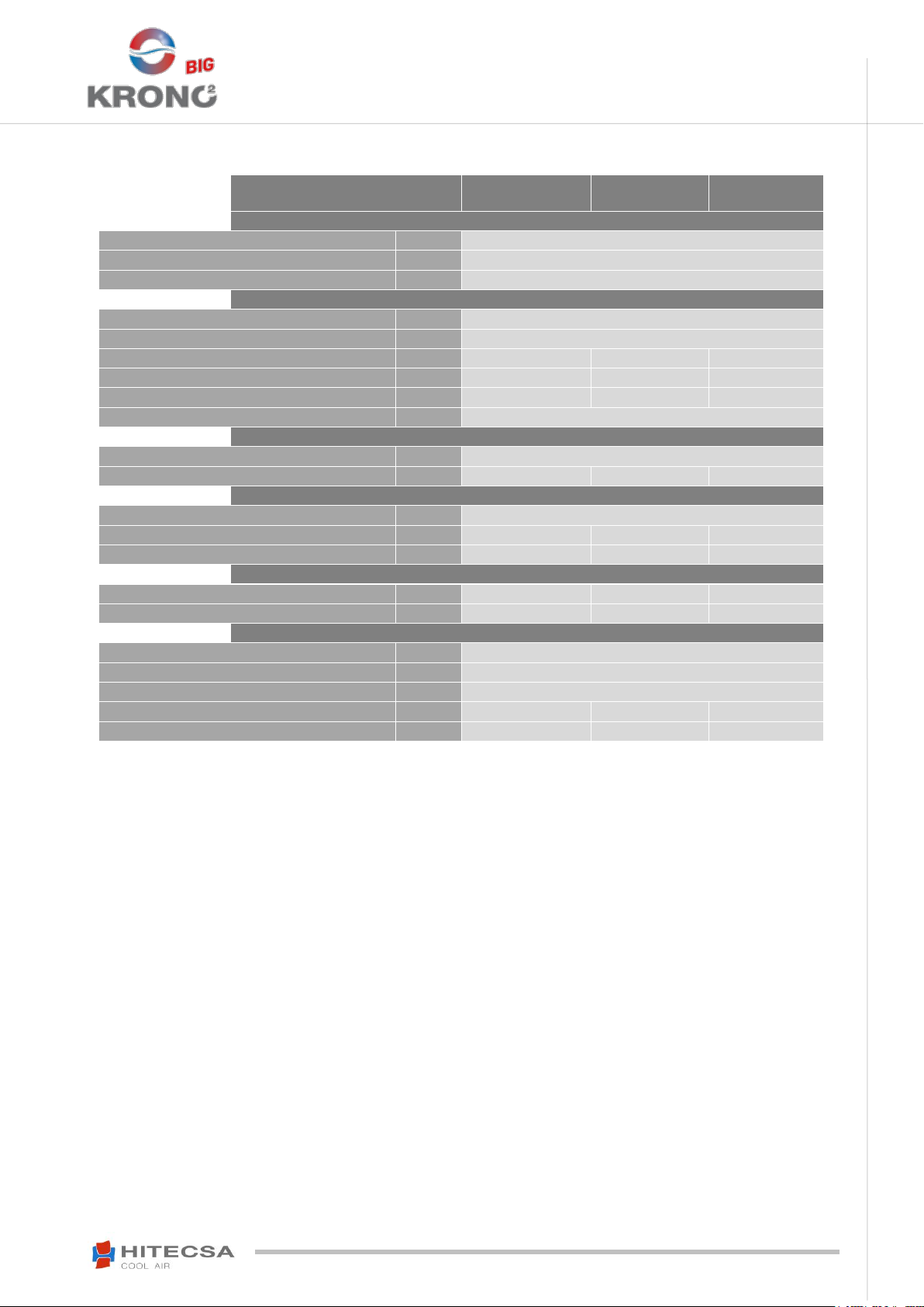
KRONO 2 series
7002.4
8002.4
9002.4
HYDRONIC KIT
Expansion Vessel Volume
l
50
Deposit Inertia Volume
l
300
Available Pressure Machine + H.K. Without Tank
kPa
104,2
118,4
129,2
Available Pressure Machine + H.K. With Tank
kPa
114
129,8
141,6
Water Flow
m3/h
33
35,5
37
Connection Type
Slotted - Victaulic
Connection Diameter
(“)
3
HEAT PUMP OPTION
Power Supply
V/~/Hz
400/3/50
Number of Heat Pump
2
Reserve Heat Pump Option
SI
Maximum weight: Heat Pump + H.K. (full of water)
kg
2245
2278
2284
LOW PRESSURE PUMP
Model
CEA 370/2
Rated Power (per unit)
kW
1,5
Maximum Current (One Pump Operation)
A
3,4
Locked Rotor Current (One Pump)
A
28
Available Pressure Machine + H.K. Without Tank
kPa
66
46,4
32,2
Available Pressure Machine + H.K. With Tank
kPa
56,2
35,1
19,9
HIGH PRESSURE PUMP
Model
CEA 370/5
Rated Power (per unit)
kW
3
Maximum Current (One Pump Operation)
A
5,9
Locked Rotor Current (One Pump)
A
51,2
Available Pressure Machine + H.K. Without Tank
kPa
157,9
139,2
125,5
Available Pressure Machine + H.K. With Tank
kPa
148,1
127,8
113,2
HYDRONIC KIT
TECHNICAL DATA
26
Page 27

05.17 207646 Rev.103
EKWXA│EKWXBA
AIR-COOLED WATER CHILLERS
AXIAL FANS
OPERATING LIMITS
7002.4
8002.4
9002.4
Coefficient of thermal expansion Water between 7-50°C / 2 bar
ΔV/V
0,0125
Coefficient of thermal expansion Water between 7-55°C / 2 bar
ΔV/V
0,015
Expansion vessel
l
50
Maximum water volume (7-50)ºC
l
1992
Maximum water volume (7-55)ºC
l
1672
WARNING!
HYDRONIC KIT
OPERATING LIMITS
MAINTENANCE
CONSERVATION AND CLEANING
Before performing any service or maintenance of the unit, it is mandatory to disconnect and lock the system
main switch to prevent anyone other than the technician from connecting the unit and causing personal
It is advisable to do maintenance works every 1.000 operating hours as well as at the beginning of each cooling season.
Coils: At least once a year, clean condenser coils with water and detergent, then dry with air at a low pressure. Never clean with wire
brush.
Drainage system: Verify condition and good operation of the drainage tray and siphon.
Refrigeration circuit: Check for oil refrigerant leaks, noises or system’s vibrations. Take measurements of temperatures and
pressures of components and record them on the maintenance form.
Electrical circuit: Make sure that all electrical connections -wires, contactors and terminals- are properly tight. Record the readings
for volts and amperes of each compressor and fan motor. Verify the starting current. Check the good operation of all relays, pressure
switches and phase sequence relay of Scroll compressor.
injury.
LUBRICANT
R-410A refrigerant compressors use synthetic polyolester oil. Each compressor manufacturer has a specific oil for your product.
The compressor or system should not remain open to atmosphere for more than 15 minutes.
Synthetic ester-type lubricants (POE, Polyol Ester) having high solubility with R-410A are used. Since these types of oils are very
hygroscopic, it should be more careful handling them than with conventional ones. Moreover, when these synthetic oils are mixed with
minerals or alkylbenzenes, they deteriorate causing capillary blockage or failure in the compressor.
Do not mix under any circumstances.
27
Page 28

05.17 207646 Rev.103
EKWXA│EKWXBA
AIR-COOLED WATER CHILLERS
AXIAL FANS
CONDENSATION CONTROL
STANDARD, IC y SIL: Outdoor AC fan with variable speed drive
SS: Serial Built-in Speed Control
POWERED FAN
Incorporation of EC Electronic Fans of bionic profile with higher available pressure
With this accessory is included the control of condensation of the equipment
SOFT STARTER
Soft starter to minimize peak currents at the compressor start
ELECTRONIC EXPANSION
Expansion of electronic injection valve
HYDRONIC KIT
Option 1: Pump + Tank + Expansion vessel
Option 2 : Pump + Tank with electrical heater + Expansion vessel
In HEAT mode for low outdoor temperatures, the electric heater is activated as a compressor
support, as long as the compressor is operational
Option 3 : Pump + Expansion vessel
WATER MANOMETERS
Incorporation of manometers for reading the inlet and outlet pipes
AGGRESSIVE
ENVIRONMENTS
Coils with Blygold coating of finned pack
Coils with Aluzinc flap type
Coils with copper fins
COIL PROTECTION
Incorporation of protection grids to prevent impact on the condenser coils
SUPERVISION
External monitoring system
MULTIPLE UNITS
MANAGEMENT
Modular control system via master/slave
WARNING!
WARNING!
MAINTENANCE
REFRIGERANT CHARGE
Never use oxygen to pressurize system or purge lines for leak test. Oxygen reacts violently with
oil, which can cause an explosion resulting in damage, personal injury or death.
In case it is necessary to add or recover refrigerant, use an electronic scale that is suitably reinforced and prepared to withstand the
handling of the refrigerant bottle.
The charge must be made in LIQUID condition.
The inlet of liquid refrigerant R-410A in the empty tubes causes temperatures below 0ºC until the internal pressure reaches 7 bars.
If it is necessary to make brazing operation, first fill the circuit with dry nitrogen. Burning
refrigerant 410A results in toxic gas emissions.
Leaks should be repaired immediately.
Never overcharge the system.
Never use compressor as vacuum pump.
If leakage symptoms appear during the operation, it is necessary to leak test.
To find small leaks, you will need a detector for HCF.
If gas leak is detected is necessary to remove and recuperate complete refrigerant charge. Pressurize system with dry nitrogen. If
leakage has been not detected break a vacuum, dehydrate and charge with refrigerant.
Do not reintroduce used refrigerant, send it to an authorized recycling location.
OPTIONAL
ACCESSORIES / OPTIONAL
* In addition to these optional consult with our Commercial department for any other configuration or function not described as available.
28
Page 29

05.17 207646 Rev.103
EKWXA│EKWXBA
AIR-COOLED WATER CHILLERS
AXIAL FANS
Refrigerant Data
Safety Data: R410A
Toxicity
Low
Contact with Skin
R410A vapours can irritate the skin and eyes. In liquid form, it can freeze skin on
contact. If contact with skin occurs, flush the exposed area with lukewarm water until
all of the chemical is removed. If there is evidence of frostbite, bathe in lukewarm
water.
Contact with Eyes
If contact with eyes occurs, immediately flush with large amounts of lukewarm water
for at least 15 minutes, lifting eyelids occasionally to facilitate irrigation. Seek medical
attention as soon as possible.
Ingestion
Very unlikely - should something happen, it will cause frost burns. Do not induce
vomiting. Only if the patient is conscious, wash out mouth with water and give some
250 ml of water to drink. Then, obtain medical attention.
Inhalation
Inhalation of the R410A vapour may cause irritation. Vapour inhalation at high
concentrations may result in asphyxiation or the heart may become sensitized,
causing cardiac arrhythmia. When concentration of R410A reach levels which reduce
oxygen to 14-16% by displacement, symptoms of asphyxiation will occur. An
individual exposed to high concentrations of R410A must be given medical attention
immediately. Adequate ventilation must be provided at all times.
Recommendations
Semiotics or support therapy is recommended. Cardiac sensitisation has been
observed that, in the presence of circulating catecholamines such as adrenalin, may
cause cardiac arrhythmia and accordingly, in case of exposure to high
concentrations, cardiac arrest.
Prolonged Exposure
R410A: a study on the effects of exposure to 50,000 ppm during the whole life of rats
has identified the development of benign testicle tumour.
This situation should therefore be negligible for personnel exposed to concentrations
equal to or lower than professional levels.
Professional Levels
R410A: Recommended threshold: 1000 ppm v/v - 8 hours TWA.
Stability
R410A: is stable under normal operating conditions.
Conditions to Avoid
Do not use in the presence of high temperatures, flames, burning surfaces and
excess humidity.
Hazardous Reactions
Contact with certain red-hot metals may result in exothermic or explosive reactions
and yield toxic and/or corrosive decomposition products. Specific materials to avoid
include freshly abraded aluminium surfaces and active metals such as sodium,
potassium, calcium, powdered aluminium, magnesium and zinc.
Hazardous Decomposition
Products
R410A: Halogen acids produced by thermal decomposition and hydrolysis.
APPENDIX: SAFETY DATA R410A
29
Page 30

05.17 207646 Rev.103
EKWXA│EKWXBA
AIR-COOLED WATER CHILLERS
AXIAL FANS
Refrigerant Data
Safety Data: R410A
General Precautions
Do not inhale concentrated vapours. Their concentration in the atmosphere should
not exceed the minimum preset values and should be maintained below the
professional threshold. Being weightier than the air, the vapour concentrates on the
bottom, in narrow areas. T here fore, the exhaust system must work at low level.
Respiratory System Protection
If you are in doubt about the concentration in the atmosphere, it is recommended to
wear a respirator approved by an accident prevention Authority, of the independent
or oxygen type.
Storage
Cylinders must be stored in a cool, dry and properly ventilated storage area away
from heat, flames, corrosive chemicals, flumes, explosives and be otherwise
protected from damage. Keep a temperature below 52°C.
Protective Clothing
Wear overalls, protective gloves and goggles or a mask.
Accidental Release Measures
IIt is important to wear protective clothing and a respirator. Stop the source of the
leak, if you can do this without danger. Negligible leaks can be left evaporating under
the sun, providing that the room is well ventilated. Considerable leaks: ventilate the
room. Reduce the leak with sand, earth or other absorbing substances. Make sure
that the liquid does is not channelled into gutters, sewers or pits where the vapours
are likely to create a stuffy atmosphere.
Disposal
The best method is recovery and recycling. If this method is not practicable, dispose
according to an approved procedure, which shall ensure the absorption and
neutralization of acids and toxic agents.
Fire Fighting Information
R410A: Not flammable in the atmosphere.
Cylinders
The cylinders, if exposed to fire, shall be cooled by water jets; otherwise, if heated,
they may explode.
Protective Fire Fighting Equipment
In case of fire, wear an independent respirator and protective clothing.
APPENDIX: SAFETY DATA R410A
30
Page 31

05.17 207646 Rev.103
EKWXA│EKWXBA
AIR-COOLED WATER CHILLERS
AXIAL FANS
We reserve the right to add modifications without prior notice.
31
 Loading...