

Hitecsa ECVBZ, CCVBZ, ECVZ, CCVZ, ACVBZ Installation, Operation And Maintenance Instructions
...Page 1
IOM 3.2 / HE OCT 2002
HITECSA
ISO 9002
EN29002
UNE66902
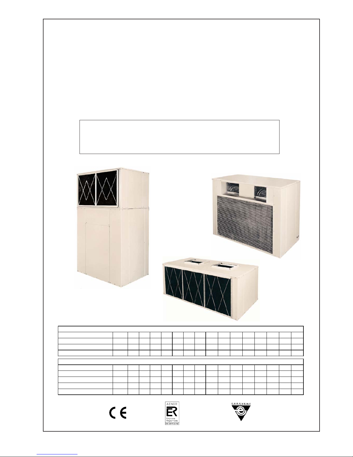
VERTICAL AIR COOLED AIR CONDITIONERS
& AIR TO AIR HEAT PUMPS
Self Contained (ACVZ, ACVBZ series)
& Split Systems (CCVZ/ECVZ, CCVBZ/ECVBZ series)
Installation, operation
and maintenance instructions
Self Contained ACVZ 351 401 501 701 721 751 801 1001 1002 1201 1402 1502 2002 2302 2402
Split, outdoor sectio CCVZ 351 401 501 701 721 751 801 1001 1002 1201 1402 1502 2002 2302 2402
Split, indoor section ECVZ 351 401 501 701 721 751 801 1001 1002 1201 1402 1502 2002 2302 2402
Nominal cooling capacity kW
10,0 11,5 14,9 18.7 19,5 22,2 23,4 30,0 29,8 36,0 37,4 44,4 60,0 67,0 72,0
Self Containe ACVBZ 351 401 501 701 721 751 801 1001 1201 1402 1502 1602 2002 2302 2402
Split, outdoor section CCVBZ 351 401 501 701 721 751 801 1001 1201 1402 1502 1602 2002 2302 2402
Split, indoor sectio ECVBZ 351 401 501 701 721 751 801 1001 1201 1402 1502 1602 2002 2302 2402
Nominal cooling capacity kW
9,8 11,5 14,7 18.6 19,4 22,1 23,2 29,7 35,0 37,2 44,2 46,4 59,4 66,0 70,0
Nominal heating capacity kW
10,4 12,7 15,6 19.6 20,6 23,5 24,4 31,7 37,0 39,2 46,6 48,8 63,4 70,0 74,0
COOLI NG MODELS
HEAT PUMP MODELS
Page 2
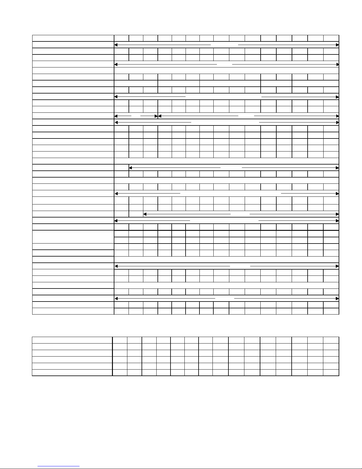
ELECTRICAL DATA
+ Models 230/3/50 are available on special request.
++ D-Direct; B-Belt drive.
+++ V- Expansion Valve.
(*) Based on an outdoor air dry bulb temperature of 35ºC and an indoor air wet bulb
temperature of 19ºC.
(**) Based on an outdoor air dry bulb temperature of 46ºC and an indoor air wet bulb
temperature of 21ºC.
MODEL ACVZ
NOMINAL POWER INPUT kW
* NOMINAL CURRENT A
MAXIMUM POWER INPUT kW
** MAXIMUM CURRENT A
UNIT STARTING AMPS A
351 401 501 701 721 751 801 1001 1002 1201 1402 1502 2002 2302 2402
4,7 5,2 6,4 7,0 8,8 9,4 10,2 12,4 12,7 17,3 14,0 18,4 25,9 27,4 32,9
8,0 8,8 10,9 11,9 14,9 16,0 17,3 21,1 21,6 29,4 23,9 31,2 44,0 46,5 56,0
5,6 6,2 7,6 8,4 10,5 11,2 12,2 14,8 15,2 20,6 16,8 22,0 30,9 32,6 39,3
9,6 10,5 13,0 14,2 17,8 19,1 20,7 25,2 25,8 35,1 28,5 37,3 52,5 55,4 66,8
46 50 56 82 100 101 94 122 63 154 91 114 144 170 170
MODEL ACVZ
Unit Operating Weight kg
Refrigerant Charge kg
Control Circuit Voltage V
OUTDOOR SECTION CCVZ
Operating Weigh t kg
COMPRESSOR Type
Quantity
Face Area sq.m
Rows
Fins / meter
FAN
Quantity
Nominal Air Flow l/s
Transmission ++
MOTOR
Voltage
Nominal HP
INDOOR S ECTION ECVZ
Operating Weigh t kg
COIL
Face Area m
2
Rows
Fins / meter
FAN
Quantity
Power supply +
COIL
Nominal Air Flow l/s
Transmission ++
MOTOR
Voltage
Nominal HP
Expansion System +++
AIR FILTER
Quantity
Thickness mm
Width ea. mm
Height ea. mm.
Model
351 401 501 701 721 751 801 1001 1002 1201 1402 1502 2002 2302 2402
235 254 282 344 360 372 380 485 555 495 564 620 895 904 920
2,5 3,0 3,6 4,7 5,1 5,7 5,9 6,0 2x3,6 8,2 2x4,7 2x4,8 2x7,8 2x8,6 2x9,0
165 172 215 225 235 250 253 350 345 360 488 506 591 616 616
111111112122222
0,360 0,400 0,450 0,720 0,720 0,720 0,720 1,260 1,260 1,260 1,260 1,260 1,757 1,757 1,757
455445533555666
111111122222222
10/10 12/12 12/12 15/15 15/15 15/15 15/15 15/11 15/11 15/11 15/11 15/11 18/18 18/18 18/18
DD SS SS SS SS SS SS G2L G2L G2L G2L G2L G2L G2L G2L
944 1055 1222 2111 2111 2277 2333 3111 3472 3472 3472 3888 5000 5000 5277
DBBBBBBBBBBBBBB
230/1
1/3 3/4 1,0 1,5 1,5 2,0 2,0 2,0 2,0 3,0 3,0 4,0 5,5 5,5 5,5
85 89 95 126 126 133 133 160 210 170 266 268 304 304 304
0,252 0,310 0,350 0,540 0,540 0,540 0,540 0,840 0,840 0,840 0,840 0,840 1,202 1,202 1,202
444444433444555
476 555
111111122222222
400/3/50
24
Reciprocating
3/8"Copper tubes/aluminum fins
555 476
Reciprocating Scroll Reciprocating Scroll
Double Suction Centrifugal
400/3
3/8" Copper tubes/aluminum fins
476
Double Suction Centrifugal
10/10 10/10 10/10 12/12 12/12 12/12 12/12 12/12 12/12 12/12 12/12 12/12 15/11 15/11 15/11
DD DD SS SS SS SS SS G2L G2L G2L G2L G2L G2L G2L G2L
639 667 944 1167 1222 1333 1444 1944 1944 2222 2278 2444 3111 3333 3444
DDBBBBBBBBBBBBB
1/3 1/3 3/4 1,0 1,0 1,5 1,5 1,5 1,5 2,0 2,0 2,0 4,0 4,0 4,0
R R R V V V V V V(2) V V(2) V(2) V(2) V(2) V(2)
111222233333333
650 650 730 486 486 486 500 500 500 500 500 500 633 633 633
528 528 528 587 587 587 587 590 590 590 590 590 635 635 635
400/3
10
PHYSICAL AND ELECTRICAL DATA
COOLING MODELS
2
Page 3
3
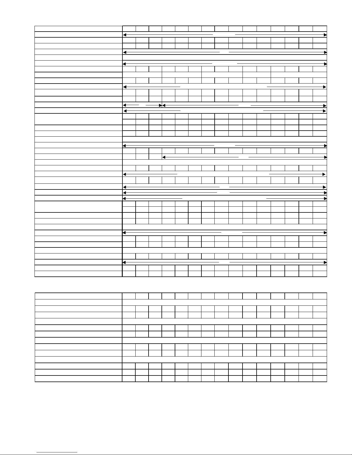
ELECTRICAL DATA
+ Models 230/3/50 are available on special request.
++ D-Direct; B-Belt drive.
+++ V- Expansion valve; C- Capillary tubes; R- Restrictor.
(*) Based on an outdoor air dry bulb temperature of 35ºC and an indoor air wet bulb temperature of 19ºC.
(**) Based on an outdoor air wet bulb temperature of 6ºC and an indoor air dry bulb temperature of 20ºC.
(***) Based on an outdoor air dry bulb temperature of 46ºC and an indoor air wet bulb temperature of 21ºC.
(****) Based on an outdoor air wet bulb temperature of 18ºC.
MODEL ACVBZ
NOMINAL POWER INPUT kW
COOLING *
HEATING**
NOMINAL CURRENT A
COOLING *
HEATING**
MAXIMUM POWER INPUT kW
COOLING ***
HEATING****
MAXIMUM CURRENT A
COOLING ***
HEATING****
UNIT STARTING AMPS A
351 401 501 701 721 751 801 1001 1201 1402 1502 1602 2002 2302 2402
4,7 5,2 6,4 7,0 8,8 9,4 10,2 12,4 17,3 14,0 18,3 22,6 25,9 27,4 32,9
3,9 4,3 5,5 6,7 7,7 8,8 9,1 11,4 12,6 13,3 17,3 19,8 23,7 26,2 26,7
8,0 8,8 10,9 11,9 14,9 16,0 17,3 21,1 29,4 23,9 31,1 38,5 44,0 46,5 56,0
6,7 7,3 9,4 11,4 13,1 14,9 15,5 19,3 21,4 22,5 29,4 33,6 40,3 44,5 45,3
5,6 6,2 7,6 8,4 10,5 11,2 12,2 14,8 20,6 16,8 22,0 27,0 30,9 32,7 39,3
4,6 5,0 6,5 7,9 9,1 10,4 10,7 13,4 15,1 15,6 20,4 23,3 27,9 30,8 31,5
9,6 10,5 13,0 14,2 17,8 19,1 20,7 25,2 35,1 28,5 37,3 45,9 52,5 55,6 66,8
7,9 8,6 11,1 13,4 15,4 17,6 18,3 22,8 25,7 26,5 34,6 39,6 47,4 52,4 53,5
44 48 54 82 98 100 93 121 151 86 109 103 136 170 168
MODEL ACVBZ
Powe r supply +
Unit Operating Weight kg
Refriger ant Charge kg
Control Circuit Voltage V
OUTDOOR SECTION CCVBZ
Voltage
Operating Weight kg
COMPRESSOR Type
Quantity
COIL
Face Ar ea
m
2
Rows
Fins / meter
FAN
Nominal Air Flow l/s
Transmission ++
MOTORS
Voltage
Nominal HP
Expansion System +++
INDOOR SECTION ECVBZ
Operating Weight kg
COIL
Face Ar ea
m
2
Rows
Fins / meter
FAN
MODEL
Nomi nal A ir Flo w l/s
Transmission ++
MOTORS
Voltage
Nomi nal H P
Expansion System +++
AIR FLITER
Quantity
Thickness mm
Width ea. mm
Height ea. mm
MODEL
10/10 10/10 10/10 12/12 12/12 12/12 12/12 12/12 12/12 12/12 12/12 12/12 15/11 15/11 15/11
DD SS SS SS SS SS SS G2L G2L G2L G 2L G2L G2L G 2L G2L
639 778 944 1167 1222 1333 1444 2000 2222 2333 2555 2666 3111 3333 3555
DBBBBBBB B B B B B B B
1/3 3/4 3/4 1,0 1,0 1,5 1,5 1,5 2,0 2,0 3,0 3,0 4,0 4,0 4,0
RRRVVVVV VV(2)V(2)V(2)V(2)V(2)V(2)
1112222 2 2 3 3 3 4 4 4
650 650 730 486 486 486 486 647 722 500 500 500 633 633 633
528 528 528 587 587 587 587 610 610 590 590 590 635 635 635
400/3
10
351 401 501 701 721 751 801 1001 1201 1402 1502 1602 2002 2302 2402
251 276 290 367 392 423 440 553 585 730 810 820 1080 1115 1135
3,0 3,2 3,8 5,2 5,9 6,7 6,7 7,6 8,1 2x5,8 2x6,7 2x6,7 2x7,0 2x8,3 2x8,3
172 189 200 253 272 297 304 373 397 477 538 548 747 782 802
1111111 1 1 2 2 2 2 2 2
0,360 0,400 0,450 0,720 0,720 0,720 0,720 1,125 1,260 1,440 1,440 1,440 2,200 2,200 2,200
4554455 4 5 4 5 5 5 5 5
10/10 12/12 12/12 15/15 15/15 15/15 15/15 15/11 15/11 15/15 15/15 15/15 18/18 18/18 18/18
DD SS SS SS SS SS SS G2L G2L (2) SS (2) SS (2) SS (2) SS (2) SS (2) SS
944 1055 1222 2111 2111 2278 2333 3111 3472 3777 4333 4444 6111 6111 6528
DBBBBBBB B B B B B B B
0,6 3/4 1,0 1,5 1,5 2,0 2,0 2,0 3,0 2x1,5 2x2 2x2 2x3 2x4 2x4
RRR
92 95 99 126 126 136 136 197 199 253 272 272 333 333 333
0,252 0,310 0,350 0,540 0,540 0,540 0,540 0,750 0,840 0,840 1,050 1,050 1,600 1,610 1,610
400/3/50
24
400-3-50
Reciprocating
3/8"COPPER TUBES/ALUMINUM FINS
555 476
Reciprocating Scroll Reciprocating Scroll
DOUBLE SUCTION CENTRIFUGAL
400/3
C
3/8 COPPER TUBES / ALUMINUM FINS
4
476
DOUBLE SUCTION CENTRIFUGAL
PHYSICAL AND ELECTRICAL DATA
HEAT PUMP MODELS
Page 4
4
GENERAL
This manual reviews general rules which must be respected during the installation and maintenance of air
conditioning systems.
Before starting the system installation read this
whole manual. Also please refer to the technical
manual and to the model being installed for more
details about its characteristics and accessories.
SAFETY PRECAUTIONS
Installation and maintenance of air conditioning equipment can be dangerous because the system is under
pressure and includes electrical components.
Only qualified and trained service technicians
should be permitted to proceed with the installation, start up and provide maintenance and
service for this equipment.
Untrained personnel can perform only basic operations
such as cleaning of air filters.
All other operations have to be made by qualified and
technically trained personnel.
During every visit follow recommendations contained
in this manual, on stickers on the unit, and take general safety precautions.
Strictly follows all safety codes. Use safety glasses and
work gloves.
Use a quenching cloth for brazing and unbrazing operations.
WARNING:
- Before starting service or maintenance, turn off the
main power switch to avoid electrical shock and injury.
- When repairing the unit, use original spare parts and
install them in the same place as the old parts.
- During the system operation, some elements of refrigeration cycle can reach temperatures above 70°C and
for this reason only qualified and trained technicians
should have access to the units components.
- Never install the units in explosive atmosphere.
EQUIPMENT RECEPTION
1. Inspect the packing. Inspect the unit. If it is damaged, or if the shipment is incomplete, immediately
file a claim with the shipping company.
2. Check that the local power supply agrees with the
specification on the unit nameplate.
INSTALLATION LOCATION
Check the following points:
1. The construction must be able to support the unit
operating weight.
2. Allow sufficient space for servicing and air flow access around the outdoor units.
3. Select a location free of dust or foreign matter which
may cause coils clogging.
4. When the outdoor unit is installed on the ground,
be sure to choose a location which cannot be flooded. It
is important to ensure at all time water evacuation
out of the unit (rain water, condensation water and
water from coil defrost in the case of heat pump system).
5. Consult and respect all regulations concerning installation of air conditioning equipment.
6. Vibration isolators pads should be provided to prevent noise transmission.
UNIT SUPPORT
Due to the size and the weight of air conditioning units
their base frame requires a support which should meet
the following conditions:
1. Support surface has to be large enough to distribute
unit weight on the building construction.
2. When the unit base has fixation holes they should
be used to keep it firmly fastened to the support.
3. The structure should support the units operational
weight.
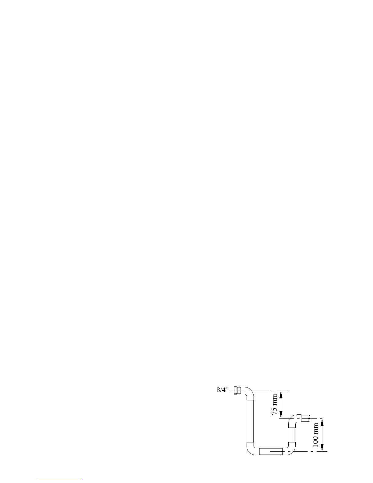
CONDENSATE AND RAIN
WATER EVACUATION
CONDENSING UNITS: Units with centrifugal fans,
heat pump models, have a drain tube connection to
remove condensate and defrost water.
INDOOR UNITS: They have a drain pan to collect condensation water with drain tube connection.
DRAIN TUBE:
1. Use only galvanized steel, copper or plastic tube. Do
not use garden hose.
2. It is necessary to provide a flexible connection in
the drain piping to eliminate possible vibrations.
Fig. 1 - Exemple of
the trap to be
made by the installer.
Page 5

5
ATTENTION: To avoid electrical shock, injury or
equipment damage, be sure that the ON-OFF power
switch is in OFF position. Field wiring must comply
with all local regulations and codes. Special attention
has to be made when making earth connections.
Supply voltage and the current has to be within 10%
of values indicated on the unit nameplate. If supply is
incorrect contact local power company.
Never operate a unit if the voltage unbalance exceeds
3%. The following formula must be used to determine
the percentage of voltage unbalance:
voltage unbalance % = largest deviation from
average voltage / average voltage.
EXAMPLE:
Nominal supply: 400.3.50
Measured voltage:
XY = 407V, YZ = 396V, ZX = 391V
Average voltage: (407+396+391)/3 =
398 V
Determine maximum deviation from average
voltage:
XY: 407-398 = 9V (= maximum deviation)
YZ: 398-396 = 2V
ZX: 398-391 = 7V
Percentage voltage unbalance: (9/398)x100 =
2.26%, <3%, therefore acceptable unbalance.
THERMOSTAT CONNECTION: Connection between the thermostat and the unit should be made
using flexible tube and to be in accordance with the
unit wiring diagram.
ATTENTION: If the unit operates at another voltage
from the specified it will loose the warranty.
ATTENTION: Compressors are mounted on
antivibration isolators. Do not remove fixing screws.
3. Provide a trap properly sized for correct water evacuation (see Fig. 1).
4. Drain piping should be located below the drain connection and should have inclination to assure proper
water flow.
AIR DUCTS
Ducts should be sized taking in consideration nominal
air flow and external static pressure of the unit.
1. Regardless of the type of the air ducts used they
cannot be flammable and cannot produce toxic gases
in the case of fire. They should have smooth inside
surface and not contaminate the air passing through
them. It is advisable to use sheet metal ducts with thermal insulation to avoid condensation on the ducts and
excessive loss of energy.
2. Connect air ducts to the unit using flexible connections so as to absorb vibrations, avoid noise transmission and make easy unit access.
3. If possible avoid installing duct elbows close to the
air outlet of the unit. If it is necessary use large radius
elbows and inside air deflectors if duct size is large
enough.
NOTE: All duct design has to be made by technicians
experienced in this matter.
ELECTRICAL
CONNECTIONS
IMPORTANT: In order to be sure that unit power supply is correct (wire entry, wires cross section, protection devices, etc..) consult electrical data table, the wiring diagram attached to the unit and check local standards concerning the installation of air conditioning
equipment.
Page 6

6
Min. 3.4 m
RIGGING
Min. 3.4 m
Min. 2 m
Outdoor section
Indoor section
1. Use spreaders to prevent
damage to the panels and coils.
2. Avoid violent movements of the
unit.
3. Never tip or roll the unit more
than 15º.
4. Check if all panels are in
correct location and are firmly
fastened with the screws.
Self contained unit
Page 7

7
RECOMMENDED SERVICE SPACE (mm)
WEIGHT DISTRIBUTION
1300
1300
1300
1300
1300
1300
1300
1300
1000
500
1000
700
Self-contained units Outdoor units
MODEL 1 2 3 4
351 63 88 38 63
401 69 97 41 69
501 73 102 44 73
701 92 128 55 92
721 98 137 59 98
751 106 148 63 106
801 110 154 66 110
1001 166 166 111 111
1201 176 176 117 117
1402 219 219 146 146
1502 246 246 164 164
1602 243 243 162 162
2002 335 335 223 223
2302 341 341 227 227
2402 341 341 227 227
Y
Z
X
1 2
3 4
WEIGHT DISTRIBUTION (kg)
MODEL 1 2 3 4
351 43 60 26 43
401 47 66 28 47
501 50 70 30 50
701 63 89 38 63
721 68 95 41 68
751 74 104 45 74
801 76 106 46 76
1001 112 112 75 75
1201 119 119 79 79
1402 146 146 97 97
1502 171 171 114 114
1602 169 169 113 113
2002 237 237 158 158
2302 242 242 161 161
2402 242 242 161 161
3002 283 283 188 188
Page 8

8
SPLIT SYSTEMS VERSION
REFRIGERANT LINES
CONNECTIONS AND
REFRIGERANT CHARGE
Units are shipped from the factory with nitrogen
charge and soldered piping connections. Piping connections should be made by qualified installer.
IMPORTANT
To connect outdoor with indoor unit always use
degreased and deoxidized copper refrigerant grade
tubes.
When making refrigerant pipes connections it is necessary to respect the following:
- Avoid small radius curves.
- Take away the nitrogen holding charge from the
refrigerant circuit.
- Select the diameter of the copper tubing taking in
consideration the distance between the indoor and
outdoor units and the unit type.
- For soldering, use silver alloy rod and be sure that
it is done in a nitrogen atmosphere.
- Insulate the refrigerant lines to avoid damage and
oxydation.
- Pull a vacuum in the refrigerant circuit till obtaining a pressure of 0.7 mm water gauge (6.9 Pa) and
maintain it for at least 2 hours.
- Charge the refrigerant circuit with the necessary
amount of refrigerant. Refrigerant charge indicated
in the technical manual is sufficient for the outdoor
and indoor units, you have to add the refrigerant quantity needed for the piping, using table 1 in accordance
with the piping length and diameter.
- Check for refrigerant leaks.
ATTENTION
For correct unit performance and longevity never under or overcharge refrigerant.
IMPORTANT
- Never use a compressor as a vacuum pump.
- Liquid refrigerant must never be introduced into the
suction line.
REFRIGERANT LINES SELECTION
When designing refrigerant lines you have to consider
different piping arrangements:
LAYOUT ACCORDING TO FIGURE 2
Suction / discharge line - Vertical run
- A trap at the base of the vertical pipe run and in-
termediate traps every 8 meters.
- Suction line, vertical run: gas velocity should be
more than 6 m/s.
LAYOUT ACCORDING TO FIGURE 3
Indoor
unit
Outdoor
unit
Heat pump Heat pump (discharge line)
Liquid line Gas line
Cooling Cooling (suction line)
Fig. 3 - Outdoor unit is below the indoor unit.
Heat pump Heat pump
(discharge line)
Gas line Liquid line
Cooling Cooling
(suction line)
Fig. 2 - Outdoor unit is installed above the indoor unit.
Outdoor
unit
Indoor
unit
Table 1:ADDITIONAL REFRIGERANT CHARGE (g/m)
Diameter 1/4" 5/16" 3/8" 1/2" 5/8" 3/4" 7/8" 1-1/8" 1-3/8" 1-5/8"
Liquid line 15 25 40 75 120 180 250 420 645 965
Suction line - - 6 14 23 34 47 81 123 185
Page 9

9
Nominal cooling capacity (kW) of one circuit
Pressure drop per 10 m. of equivalent length
Suction / discharge line. Vertical
pipe run - Fig. 3
- For heat pump systems use a trap
at the base of the vertical pipe run.
- There is no need for intermediate
trap.
- For cooling only systems traps are
not required.
- For heat pump systems keep velocity in the vertical run of suction or
discharge line more than 6 m/s.
For both options the following conditions should be observed:
- The maximum allowable speed in all
gas lines is 15 m/s.
- The suction line must have insulation and a slope of 1-2% toward the
compressor in the horizontal pipe
run.
- For long piping run it may be necessary to adjust oil charge (see table
2). For each trap and for 10 m. of
pipe above 20 m. add oil.
- In the case of downward liquid flow
with a height exceeding 10 m. it is
necessary to install a manual pressure equalization valve.
- Keep liquid subcooling at least 1°C
at the restrictor inlet. If the liquid
line has upward flow and pipe
length exceeding 15 m., for each 3.5
m. above this value provide 1°C
subcooling. In the cooling systems
subcooling can be obtained by the
contact of liquid and suction line (on
a max. length of 15 m.) creating the
heat exchange.
- For every meter of piping installed
add refrigerant according with the
table 1.
Graph 1 - Suction line
Nominal cooling capacity (kW) of one circuit
Diameter
Speed m/s
Pressure drop per 10 m. of equivalent length
Graph 2 - Discharge line
Speed m/s
Diameter
Table 2: ADDITIONAL OIL CHARGE
Diam. 3/8" 1/2" 5/8" 3/4" 7/8" 1-1/8" 1-3/8" 1-5/8"
cm³/10m 1.5 3 5 9 16 35 54 80
Page 10

10
LINE DIAMETER
DIAMETER OF GAS LINES
In the cooling operation suction line
hold gas refrigerant and in the heat
pump operation discharge line is also
gas line. Line diameter is selected in the
most unfavourable conditions. It is necessary to check for both cases.
In the case of the layout shown on figure 2 the suction line velocity will produce the worse conditions and gas line
diameter selection is for suction line. It
is necessary to check also the discharge
line. The suction and discharge calculations are done in the same way using
graphs 1 and 2 where pressure are referred to 10 meters of equivalent length
for each diameter.
For larger or smaller equivalent lengths
pressure drop is obtained in the direct
proportion. The line total pressure drop
(horizontal plus vertical pipe runs) must
never be higher than 20 kPa.
DIAMETER OF LIQUID LINES
To determine the liquid line diameter
use graph 3, the pressure drop in this
line should be below 68 kPa.
Nominal cooling capacity (kW) of one circuit
Pressure drop per 10 m. of equivalent length
Diameter
Graph 3 - Liquid line.
START UP
PRELIMINARY CHECK UP
It is very important to check the following points before first unit start up:
1. All the electrical connections are well tight.
2. Unit is level installed and has proper supporting
structure.
3. Air ducts have been not damaged during the installation.
4. Air filters are correctly mounted and are clean.
5. All panels are at their place and the screws tights.
6. Unit has easy maintenance and service access.
7. Openings and/or drain connections for rain and defrost (heat pumps) water evacuation are not blocked.
8. Check if there are no refrigerant leaks.
9. Electrical power source agrees with the unit nameplate rating.
10. Check for proper fan rotation.
ATTENTION: The compressors are mounted on vibration isolators. Check if mounting bolts have been not
loosen or removed by mistake.
UNIT START UP
Start up must be performed by qualified and
trained service personnel.
ATTENTION, CRANKCASE HEATER: to avoid refrigerant condensation in the compressor(s) and refrigerant absorbtion in oil when not operating, compressors are fitted with a crankcase heater. This electrical
resistance is connected on normally closed contacts
from the compressor(s) contactor(s), thus when main
power of the unit is live the heating is effective only
when the conpressor(s) is(are) not running.
Make sure that this heating element is under power
for at least 24 hours before the first start up of the compressor (thermostat on "OFF" position).
At start up time a check list of all parameters must be
established. Consult, and eventually modify, this check
list when servicing the unit and for maintenance operations.
Page 11

11
DEFROST (Heat pump systems)
At low outdoor temperature during heating cycle and
depending on air humidity, frost will appear on the
outdoor coil. It is necessary to remove the ice for proper
continuation of the heating cycle. This is done automatically with a device, operating in function of time
and temperature of the surface of the heat exchanger,
producing defrost by hot gas injection.
During this cycle, the auxiliary electrical heating coil
(option) is connected to compensate for heating. For
units with two compressors, the automatic defrost is
independent for each refrigeration circuit.
FANS
When static pressure and air flow requirements differ
from nominal ratings, centrifugal fan speed can be
adjusted to obtain specific air flow and static pressure.
Consult fan curves shown in the technical manual.
For proper and reliable operation of the system, air
flow should within ± 10% of the nominal air flow indicated on the fan curves.
To change fan speed:
1- Slide the motor along it's track to remove the transmission belt.
2- Loose the motor pulley set screws 2 and rotate pulley flanges as necessary.
3- Tighten set screws 2.
4- Replace transmission belt(s) in the pulley channel.
5- If needed, tighten the belt(s) using tension screw
nut and washer 6. Refer to Fig. 4.
1- Motor support 5- Transmission belt
2- Motor pulley 6- Tensor screw
3- Set screw 7- Fan pulley
4- Motor 8- Fan scroll
Fig. 4 - Fan speed adjustment
1- Fixed flange
2- Set screw
3- Movable flange
4- Ruler straight edge must be parallel with the belt.
5 + 7- Motor and fan shafts has to
be parallel
6- Pulleys
In order to align motor and fan pulleys:
1- Loose fan pulley set screw, slide it along the pulley
shaft and align with the motor pulley using a ruler to
check that is in parallel position to transmission belt
(see Fig. 5).
2- Tighten fan pulley screws.
Fig. 5 - To align motor and fan pulleys.
Page 12

12
MAINTENANCE
It is advisable to make maintenance visits every 1000
hours of the system operation, or every cooling season.
During every visit check the following
DRAIN: If drain pan is clean, water drain is not obstructed, and water can flow from the drain pan, drain
pipe and the trap.
AIR FILTERS: Clean the filters after 4 hours of system operation and every 3 months, or more often depending on the application. Clean filters elements by
immersing in warm water detergent solution, rinse
with clean water and carefully dry before installing
them in their place.
CENTRIFUGAL FANS: Check and adjust belt transmission every 15 days during the first month from the
start up and later every 1000 hours. Motor and fan
have self lubricating bearings and do not need additional lubrication.
REFRIGERATION CIRCUIT: Check for refrigerant
and oil leaks in the system, or for vibrations and compressor unusual noises. Take note of operating pressures.
When the system is running and that symptoms of refrigerant charge loss are detected (abnormal low cooling capacity or low pressure pressostat tripping), it is
necessary to make a leak test. If result is not satisfactory follow with gas tightness test using compressed
nitrogen. It has to be performed by an experienced
service technician. First all refrigerant must be removed from the circuit and stored in a tank.
IMPORTANT: Never use the compressor as a vacuum
pump. If more refrigerant is needed add gas very slowly
via the suction line. Liquid refrigerant must never be
introduced into the suction line. Fill in the refrigerant
charge indicated in the nameplate, plus the required
charge for the refrigerant lines, if the system is a split
system.
ELECTRICAL CIRCUIT: Make sure that there are
no faulty terminals or contactors, etc..
Be sure that all electrical connections are properly
tightened. Take measurements of the tension and
amperage of each phase and check if they are within
operation limits of the unit. Check the operation of all
the relays, high and low pressure pressostat, etc..
When unit has scroll compressors check if phases sequence safety relay is working properly.
CONDENSER COILS: Once a year clean condenser
coils (use water detergent solution, dry with air at the
pressure of around 6 bars). Never use for coil cleaning
the wire brush.
ATTENTION
Never switch off or disconnect the power supply of the compressors
crankcase heaters.
If, for any reason it is necessary to shut down the complete installation, first stop the compressors operation by selecting the "OFF" position on the thermostat, then disconnect the main power supply.
After a shut down period of some days it is mandatory to energise
the crankcase heater for a period of at least 24 hours before new
compressor start up.
Page 13

13
REMOTE CONTROL OPERATION
CONTROL SYSTEM
The unit is controlled from a remote room thermostat.
Type of thermostat is indicated in the following table:
RTR 7007 and RTR 7035
CONTROL BUTTONS
c ON/OFF SWITCH
d TEMPERATURE SELECTOR
e FAN OPERATING MODE SELECTOR: fan oper-
ate only when system is operating in cooling or heating, or continuous fan operation.
f COOLING AND HEATING MODE SELECTOR:
thermostat is controlling room temperature when the
system is operating in cooling or heating mode.
USER'S SETTING POSSIBILITIES
STARTING UP THE SYSTEM - Displace the ON/OFF
selector c to position "I".
COOLING - Select "COOL" position with selector f.
Adjust required room temperature with knob d. If this
temperature is below the effective room temperature
the compressor will operate after a time delay.
HEATING - Select "HEAT." position with selector f.
Adjust required room temperature with knob d.
Cooling systems with auxiliary heater: If this temperature is above the effective room temperature the
contactor will energize the heating element.
Heat pump systems: If this temperature is above the
effective room temperature the compressor will operate after a time delay. Auxiliary heater is controlled
by the outdoor thermostat.
FAN - Select fan operating mode with switch e: "AUTO"
(fan activated when the system is operating in cooling
or heating mode) or continuous "CONT." (not depend-
ant on system compressor operation).
SWITCHING DOWN THE SYSTEM - Displace the ON/
OFF selector c to position "0".
DSL-450, DSL-600 and DSL-700
Includes the following functions:
• Selector mode: "Cooling", "Heating", "Automatic" and
"Off".
• An electronic thermostat is controlling the room temperature in cooling and heating modes.
• An indoor fan operating mode selector.
• Two different room temperature settings.
• Optional room temperature remote sensor which allow to locate the thermostat in a distant area (by example outside the air conditioned space).
• The operating mode and selected temperature may
be locked to prevent tampering.
• Indoor temperature display.
• The selected setpoints are unaffected by power failures of any duration.
CONTROL BUTTONS
3
4 1 2
5 6
2
1
4
3
MODEL THERMOSTAT TYPE
ACV/CCV
351-501
RTR 7007
1 stage cooling / 1 stage
heating
ACV/CCV
701-3502
DSL-700
2 stages cooling / 2 stages
heating (auxiliary electric
heating)
ACVB/CCVB
351-501
RTR 7035
1 stage cooling / 1 stage
heating *
ACVB/CCVB
701-1201
DSL-450
1 stage cooling / 2 stages
heating (heat pump and
auxiliary electric heater)
ACVB/CCVB
1402-3502
DSL-600
2 stage cooling / 3 stages
heating (heat pump and
auxiliary electric heater)
* Heat pump units ACVB/CCVB 351 to 501 are delivered
with an outdoor thermostat controlling (if supplied) the
optional auxiliary electric heater contactor.
Page 14

14
c OPERATING MODE SELECTION:
Cooling Heating
Automatic OFF Disables controller
d FAN OPERATION
Show continuous fan operation.
e OUTDOOR TEMPERATURE DISPLAY (With optional sensor).
f DAY/NIGHT BUTTON
Day temperature, Night temperature.
g LOWER and h RAISE the setpoints.
USER'S SETTING POSSIBILITIES
COOLING - Select the mode with button c, cooling
symbol is blinking. Adjust the temperature with buttons g and h. Temperature setpoint display will blink
for 5 seconds. If this temperature is below the effective room temperature the compressor will start after
a time delay (or for two compressors models, if necessary the second compressor will be energized after the
first one).
HEATING - Select the mode with button c, heating
symbol is blinking. Adjust the temperature with buttons g and h. Temperature setpoint display will blink
for 5 seconds.
Cooling systems with auxiliary heater: If this temperature is above the effective room temperature the
contactor will energize the heating element. Then, if
necessary the second stage is also energized.
Heat pump systems: If this temperature is above the
effective room temperature the compressor will operate after a time delay (or for two compressors models,
if necessary the second compressor will be energized
after the first one). If necessary, as a second step (one
compressor models) or third step (two compressors
models) the auxiliary heater (electric or hot water) is
activated.
AUTO CHANGEOVER MODE - The thermostat will
automatically switch from cooling or heating mode
based on the temperature established for both modes.
FAN - Button d will select the automatic mode (fan
will operate when the system is activated in cooling or
heating mode) or continuous (not depending on the
system operation).
OFF MODE - To turn off the cooling or heating system press the button c until the word "OFF" appears
on the LCD. Fan operation is still possible in this mode.
OUTDOOR TEMPERATURE - If an outdoor remote
sensor has been installed, outdoor temperature can be
displayed by pressing the button e.
DAY/NIGHT BUTTON - By pressing the button f it
is possible to select a second (alternate or night) setting temperature. The thermostat can be alternated
between the two temperatures setpoints manually or
automatically, using any relay-based controller or clock
timer (not supplied).
CELSIUS / FAHRENHEIT - Simultaneously press g
and h to switch between Celsius (°C) and Fahrenheit
(°F) display.
Page 15

15
START-UP CHECK LIST
Equipment sold by: ................................................... Start-up date: ...........................................................
Installed by: ..............................................................
Site address: ...........................................................................................................................................................
Equipment type and serial number: ......................................................................................................................
ELECTRICAL DATA
Supply voltage Ph 1: ..................... Volts Ph 2: ..................... Volts Ph 3: ..................... Volts
Nominal voltage: ......................................... Volts % network voltage: ...........................
Currant draw: Ph 1: ..................... A Ph 2: ..................... A Ph 3: ..................... A
Control circuit voltage: ............................... Volts Control circuit fuses: .................................................. A
Main circuit breaker rating: ...................................................................................................................................
PHYSICAL DATA
CONDENSER EVAPORATOR
Entering air temperature: .............................. °C Entering air temperature: .............................. °C
Leaving air temperature: ............................... °C Leaving air temperature: ............................... °C
Pressure drop (air): ........................................ Pa Pressure drop (air): ......................................... Pa
Discharge air pressure: .................................. Pa Discharge air pressure: ................................... Pa
Fan motor input: Fan motor input:
1: ....... A 2: ....... A 3: ....... A 4: ....... A Ph. 1: ....... A Ph. 2: ....... A Ph. 3: ....... A
SAFETY DEVICE SETTINGS - CIRCUIT 1 / CIRCUIT 2 (for 2 circuits models)
High pressure switch Cut-out: ................/............... kPa Cut-in: ................/............... kPa
Low pressure switch Cut-out: ................/............... kPa Cut-in: ................/............... kPa
Oil level: ................................................................................./................................................................................
Oil visible in sight glass ?: .................................................................../...................................................................
ACCESSORIES • Low ambient kit
• Electric heating - kW: .................................................................................
• Hot water heating: ......................................................................................
Commissioning engineer (name): ..........................................................................................................................
Customer signature: Name: ...............................................
Date: .................................................
Remarks: ............................................................................................................................................................
............................................................................................................................................................
............................................................................................................................................................
............................................................................................................................................................
............................................................................................................................................................
............................................................................................................................................................
Note: Complete this start-up list at the time of installation.
Page 16

16
Subject to change without notice.
 Loading...