

Hitecsa ACVIBA HE, ACVIBA HE 40i, ACVIBA HE 45i, ACVIBA HE 55i, ACVIBA HE 80i Installation, Operation & Maintenance Manual
...Page 1
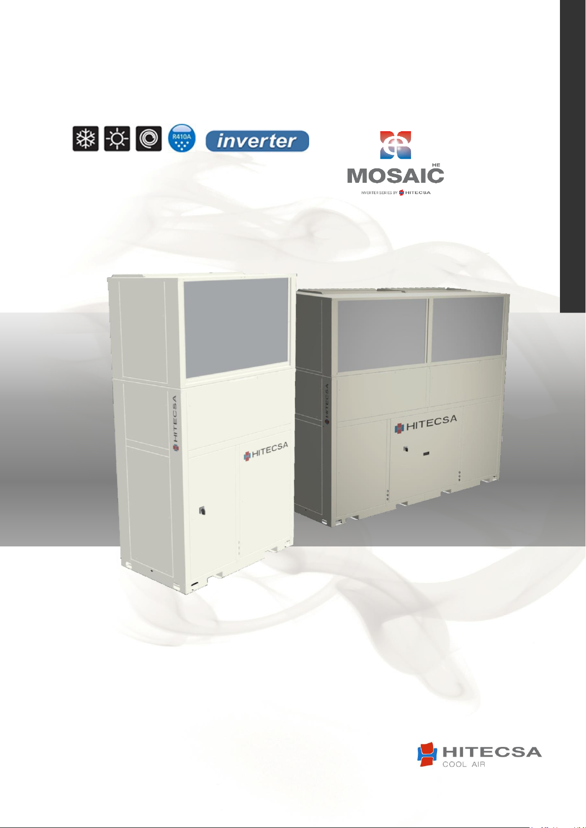
ACVIBA HE
PACKAGED AIR-AIR – COMPACT VERTICAL INVERTER
INSTALLATION, OPERATION & MAINTENANCE MANUAL
IOM_ACVIBA HE_35ia80i_207910_190501_EN
Models: 35i │ 40i │ 45i │ 55i │ 70i │ 80i
Cooling capacities: from 7.3 kW to 82.3 kW
Heating capacities: from 6.5 kW to 70.2 kW
Page 2

ACVIBA HE
IOM_ACVIBA HE_35ia80i_207910_190501_EN
Thank you for trusting the Hitecsa Products. Our company has been offering the market an extended range of specialized units for air
conditioning and cooling installations for over 35 years. Our approach is based on efficiency, flexibility and on practical solutions. This
has been the hallmark of our product catalogue.
The versatility of our factory allows us to deliver solutions that can meet any requirement and we endeavour solving any problem that
may arise in designing and implementing air conditioning installations.
From all of us at Hiplus Aire Acondicionado, once again, thank you very much.
2
Page 3

ACVIBA HE
IOM_ACVIBA HE_35ia80i_207910_190501_EN
INDEX
INTRODUCTION ................................................................................................................ 5
REGULATIONS AND CERTIFICATIONS ................................................................................ 6
SAFETY PRECAUTIONS ...................................................................................................... 7
TECHNICAL SPECIFICATIONS ............................................................................................. 9
DIMENSIONS................................................................................................................... 11
ACVIBA HE 35I – 40I ........................................................................................................ 11
ACVIBA HE 45I – 80I ........................................................................................................ 11
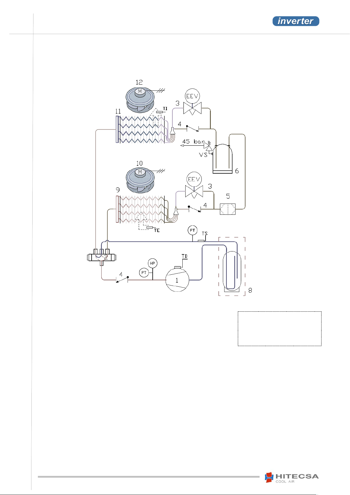
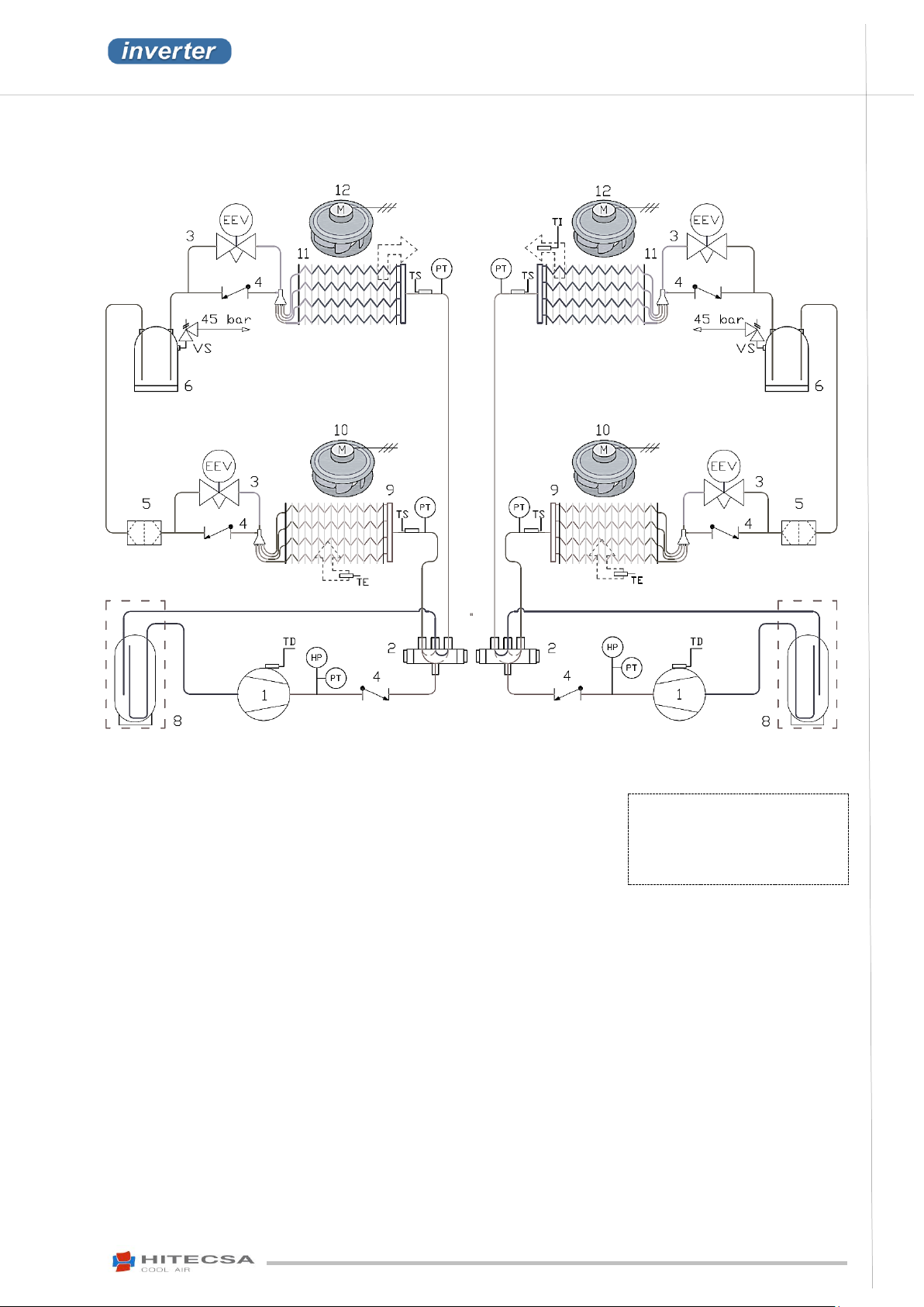
REFRIGERATION DIAGRAM ............................................................................................. 12
ACVIBA HE 35I – 40I ........................................................................................................ 12
ACVIBA HE 45I – 80I ........................................................................................................ 13
TRANSPORT .................................................................................................................... 14
INSPECTION AT RECEPTION ............................................................................................ 14
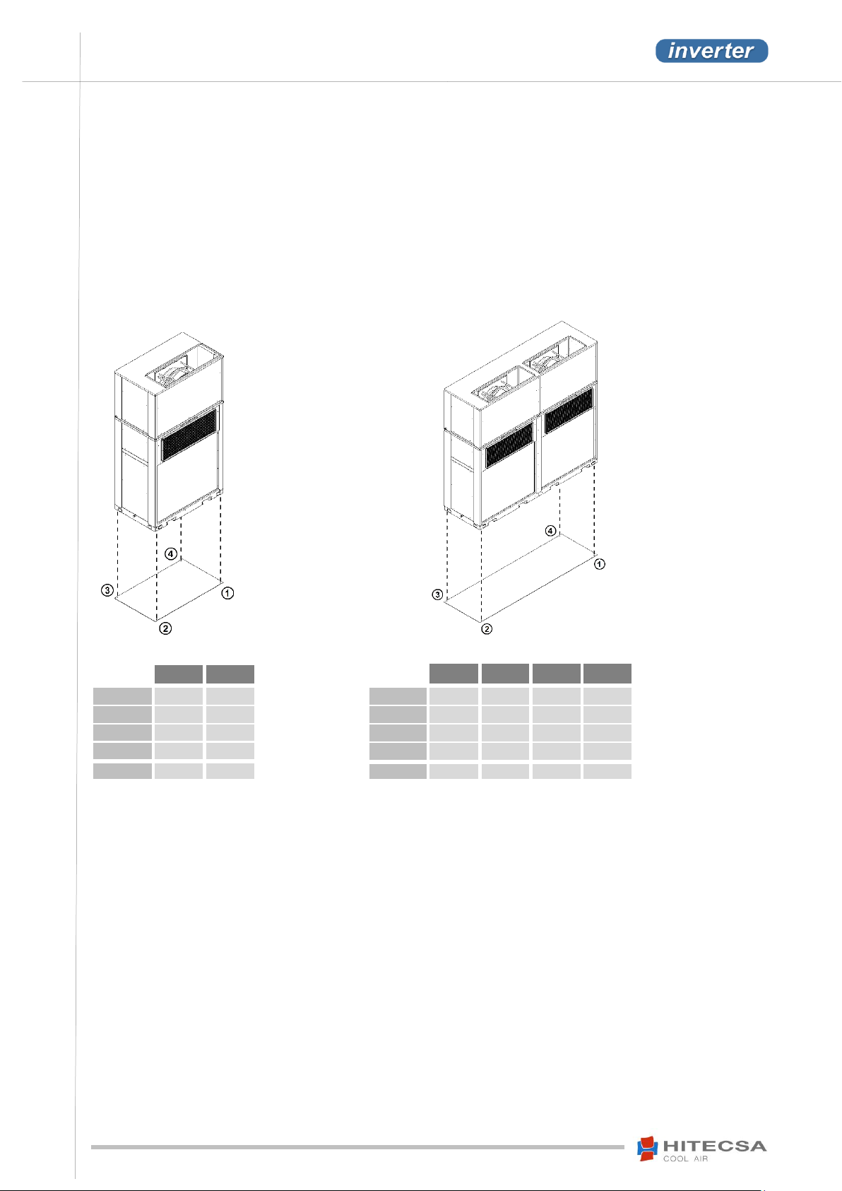
WEIGHT DISTRIBUTION (KG) ........................................................................................... 14
RIGGING ......................................................................................................................... 15
STORAGE ........................................................................................................................ 16
INSTALLATION ................................................................................................................ 17
INSTALLATION SITE ........................................................................................................ 17
SERVICE AREA (MM) ........................................................................................................ 17
UNIT SETTLEMENT ......................................................................................................... 17
DRAINAGE ...................................................................................................................... 17
AIR DUCTS ...................................................................................................................... 18
ELECTRICAL INSTALLATION ............................................................................................ 19
ELECTRICAL SPECIFICATIONS .................................................................................... 19
ELECTRICAL CONNECTIONS ...................................................................................... 19
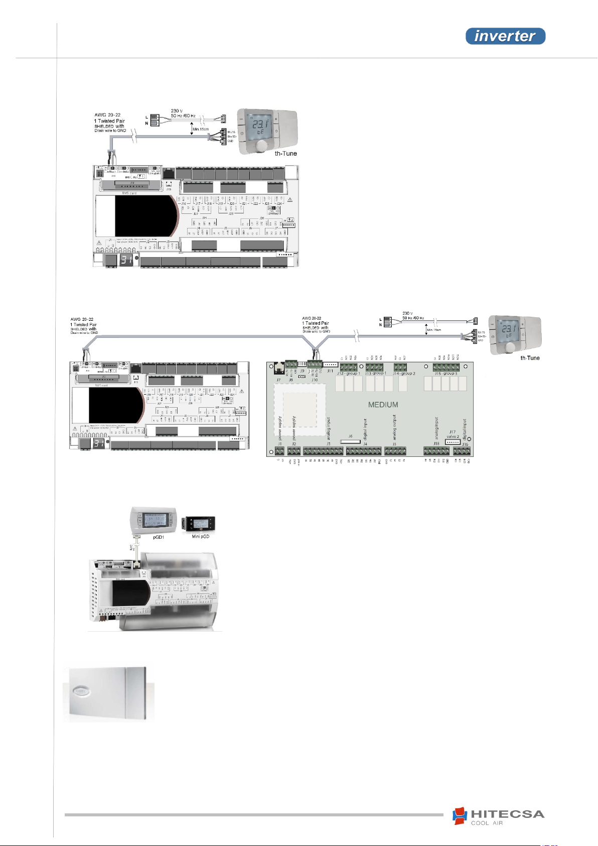
THERMOSTAT CONNECTION .................................................................................... 19
OPERATION .................................................................................................................... 21
BEFORE START-UP .......................................................................................................... 21
START-UP ....................................................................................................................... 22
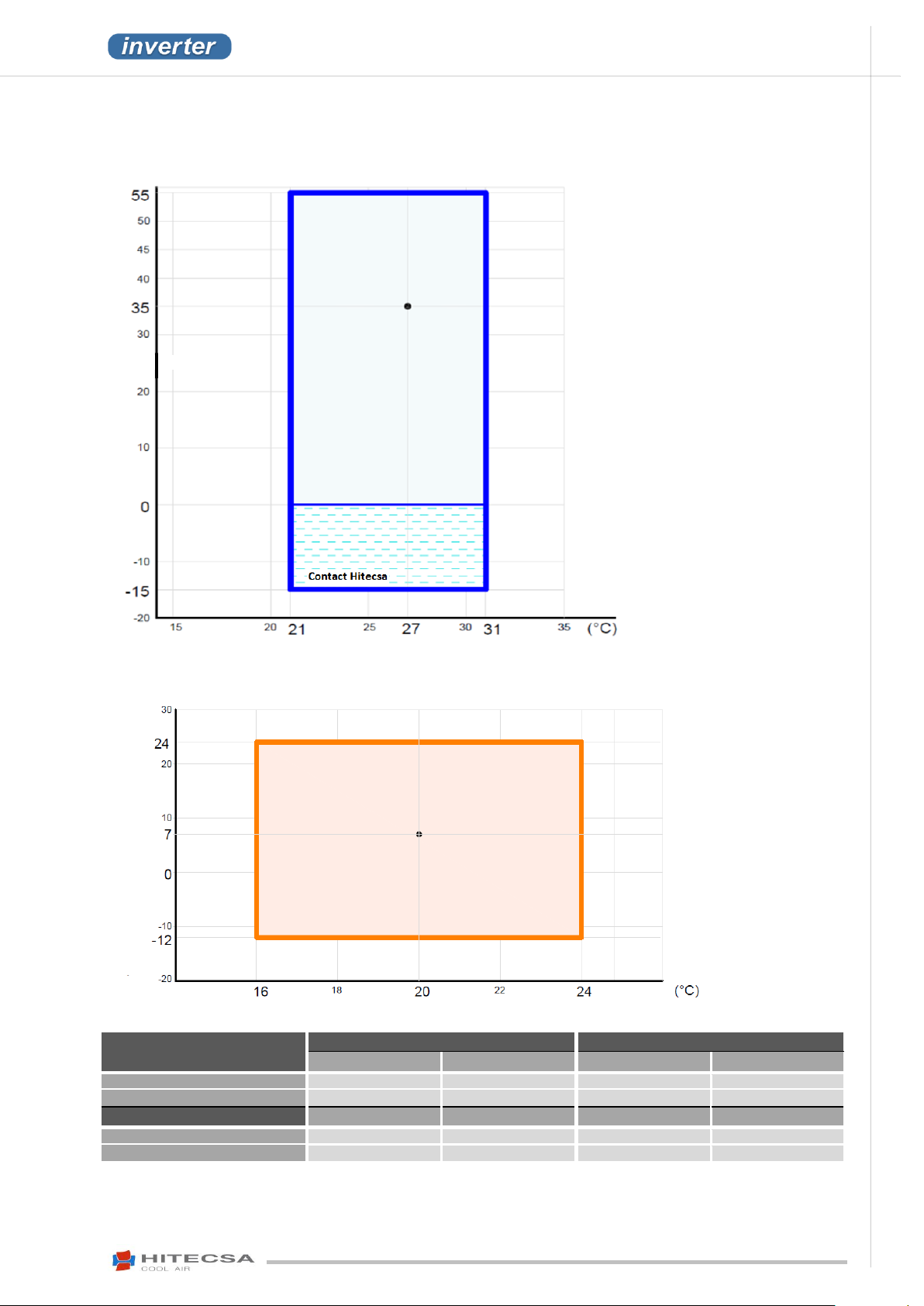
OPERATION LIMITS......................................................................................................... 23
Cooling Mode ........................................................................................................... 23
Heating Mode .......................................................................................................... 23
3
Page 4

ACVIBA HE
IOM_ACVIBA HE_35ia80i_207910_190501_EN
TH TUNE CONTROLLER ................................................................................................... 24
Display: ..................................................................................................................... 24
Start / Stop ............................................................................................................... 24
Setpoint Temperature Adjustment ........................................................................... 24
Calibration of the Th-Tune internal temperature probe ........................................... 24
Operation modes ...................................................................................................... 24
Indoor Fan Modes: ................................................................................................... 24
Time schedule ........................................................................................................... 25
Alarms ...................................................................................................................... 26
DIAGNOSIS OF THE ALARMS ........................................................................................... 26
TH TUNE - Description of the alarm codes ............................................................... 26
EC MOTOR FANS ................................................................................................................. 28
Diagnosis / Failure .................................................................................................... 28
MAINTENANCE ............................................................................................................... 30
REFRIGERANT CHARGE ................................................................................................... 30
COMPRESSOR LUBRICATION .......................................................................................... 30
CONSERVATION AND CLEANING .................................................................................... 31
REPAIRS .......................................................................................................................... 32
OPTIONS ......................................................................................................................... 33
APPENDIX: SAFETY DATA R410A ..................................................................................... 34
4
Page 5
ACVIBA HE
AIR-AIR PACKAGED UNITS
COMPACT VERTICAL INVERTER
IOM_ACVIBA HE_35ia80i_207910_190501_EN
The present manual together with any other technical document such as refrigeration or
hydraulic lines drawings, electrical diagrams among others have been issued to provide the
necessary information for the proper installation, start-up and maintenance of the unit. Therefore
it is essential to read the instructions very carefully.
Make sure that all the necessary information for the proper installation of the system is included
in the manuals supplied together with this unit and/or the rest of the indoor units, accessories,
etc. Otherwise the manufacturer declines any responsibility in case of people or animals injuries
or material damages, that may be entailed by an incorrect use of the unit and/or the noncompliance with these instructions.
In case of different interpretations and/or errors, the priority order of validity of the given
documents will be: 1. Name plate of the unit stating the specifications. 2. IOM (the present
document), 3. EDM, technical catalogue, 4. UM user manuals.
Check that the electrical network features comply with the data shown in the data nameplate of the unit.
The material of the packaging (plastic bags, insulating materials, nails, etc.) is a potential source of danger.
Therefore, it should be kept out of the reach of children and be recycled properly according to the valid
local safety regulations.
This product shall not be mixed with household waste at the end of its life. Due to the refrigerant, oil and
other components contained in this product, it must be dismantled by professional installers. Depending
on their specifications, all waste should be sent to recycling, composting or treatment plants, or to an
authorized waste management agent in accordance with the current local legislations.
INTRODUCTION
Purpose of this Manual
Storage of the Manual
This manual and the electrical diagram of the unit must be preserved and remain available to the operator for any further
consultation.
Updating the Data
The continuous improvement in design and performance to which we are committed to gives us the right to modify the
specifications of our products without prior notice.
Electrical Supply
Local Safety Regulations
Observe and analyse all possible causes of accidents that may arise in the place or places of installation of the units,
check means and tools to use, etc. It is not possible to consider every one of the potential circumstances of danger in this
manual. Respect the valid local security standards during installation.
Principles of Security on Installation
The unit has been designed and manufactured to avoid any risk for the health and safety of people. Appropriate solutions
for the project have been adopted to eliminate the possible causes of risk in the installation.
Packaging and Replacement of Equipment
5
Page 6
IOM_ACVIBA HE_35ia80i_207910_190501_EN
ACVIBA HE
AIR-AIR PACKAGED UNITS
COMPACT VERTICAL INVERTER
Carry out periodic inspections to detect possible damaged or broken parts. If these parts are not repaired
it could cause people injuries or material damages. Cut off the power supply to the unit before carrying out
any maintenance operation.
Make sure to leave the maintenance areas open. If these areas have to be necessarily invaded by the
construction of air supply and/or lateral return ducts, verify that the design of the ducts allows the access
to the fans and the change of the filters or that these are accessible from the other side.
All operations should be carried out in accordance with local safety regulations.
The reparation operations shall always be carried out by trained personal exclusively and authorized by
the manufacturer using original spare parts. The safety devices of the unit could be damaged in case of
non-compliance with these warnings.
INTRODUCTION
Utilization
The unit will be used only for the purpose it has been designed for. Any other use does not imply any kind of liability or
responsibility from the manufacturer.
Incorrect Operation
In case of breakdowns or operation faults, turn the unit off.
Periodic Inspections and Maintenance
Repairing Operations
Modifications
The manufacturer will not respond possible warranty claims and to possible damages of the unit in case of electrical and/or
mechanical modifications. The unauthorized manipulation, reparation or modification of the unit will automatically
invalidate the warranty.
Refrigerant
This product is hermetically sealed and contains R-410A which is a HFC fluorinated greenhouse gas.
REGULATIONS AND CERTIFICATIONS
ISO 9001 CERTIFICATION: HIPLUS AIRE ACONDICIONADO S.L., by endeavouring to always gain the maximum
satisfaction from their customers, obtained the ISO 9001: Quality System for its production activity. That result shows our
continuous determination to improve quality and the reliability of all our products. Our commercial activities, design, raw
materials, production processes and after-sales service represent the means to reach our goal.
CE MARKING: Our products are CE marked according to the essential requirements of the applicable EC directives and
their last modifications and comply with the national legislation of each country.
6
Page 7
ACVIBA HE
AIR-AIR PACKAGED UNITS
COMPACT VERTICAL INVERTER
IOM_ACVIBA HE_35ia80i_207910_190501_EN
DANGER
SAFETY PRECAUTIONS
Before starting any installation, service or maintenance operation, turn the main power switch off in
order to avoid electrical shock that may cause personal damages.
In case of folding electrical panels, before folding them up in order to access to the interior of the machine, it is
MANDATORY to disconnect the power supply hose from the electrical voltage, THE LINE MUST ALWAYS BE
FREE OF VOLTAGE for this operation.
It is absolutely forbidden to carry out work on electrical live parts. The protection class of the opened unit is IP00!
Check the safe isolation from the supply using a two-pole voltage detector.
Do not touch or adjust the safety elements inside any unit. For repairs use only original spare parts and install them
properly in the same position of the replaced parts.
The installation and maintenance of air conditioning equipment may be dangerous due to the pressure of the
system, the high temperature of some of its parts and the electrical components.
Do not install the unit in an explosive atmosphere.
If the motor of the fan runs independently after the unit has been switched off because it is pushed by airflow,
dangerous voltage of more than 50 V may be present in some of the internal connections of the motor. In that case
the fan is working as a generator.
When there are EC motors or motors with variable speed control, the protective earthing is conducting high
discharge currents (depending on the switching frequency, the current source voltage and the motor capacity).
Earthing in compliance with EN specifications shall therefore be observed even for testing and trial operations (EN
50 178, Art. 5.2.11). Without earthing, dangerous voltages may be present in the motor housing.
Due to the use of capacitors, danger of death exists even after switching the device off in case of direct contact with
conductive parts or with parts that carry voltage due to fault conditions. To remove or to open the housing of the
controller and the terminal box for example is only allowed after the power supply cable has been disconnected for 3
minutes.
7
Page 8
IOM_ACVIBA HE_35ia80i_207910_190501_EN
ACVIBA HE
AIR-AIR PACKAGED UNITS
COMPACT VERTICAL INVERTER
ATTENTION!
The responsibility of all personal and material damages caused by an unplanned or inappropriate
WARNING
SAFETY PRECAUTIONS
Only qualified and trained service staff (technical service) is authorized to carry out installation, commissioning and
maintenance. Unqualified personnel will carry out basic tasks only such as cleaning and replacement of filters, or
filter cleaning (excluding refrigerant filters), etc.
Prevent access to children so that they cannot play with the appliances.
For each visit, all precautions must be taken into account: those recommended in the installation, operation and
maintenance instructions, as well as the ones indicated in the stickers placed on the unit. Do not forget to strictly
follow any other legal safety precautions.
DO NOT introduce objects into the air inlets or outlets that can be drawn into the fan, people, etc.
The fan / motor may start and stop automatically due to functional reasons.
After a power failure or a main disconnection an automatic restart of the fan takes place when power supply returns!
Never approach the fan until it has stopped completely as it may be rotating even though it is not connected to the
power supply! Strong airflow could push it.
When the motor is provided with an external rotor, the rotor rotates during operation.
Use safety glasses, work gloves and any other safety accessory that may be necessary for the operation.
For brazing operations use a quenching cloth and make sure you have fire extinguisher close to you.
This product contains fluorinated greenhouse gases. In case of leakage air may be displaced which may cause lack
of oxygen when breathing.
The decomposition of fluorinated gases when being burned during brazing operations for example may cause the
presence of highly toxic and corrosive gases.
use will be born by the person or the operating company of the unit and not by the manufacturer.
All the safety recommendations must be followed carefully.
8
Page 9
ACVIBA HE
AIR-AIR PACKAGED UNITS
COMPACT VERTICAL INVERTER
IOM_ACVIBA HE_35ia80i_207910_190501_EN
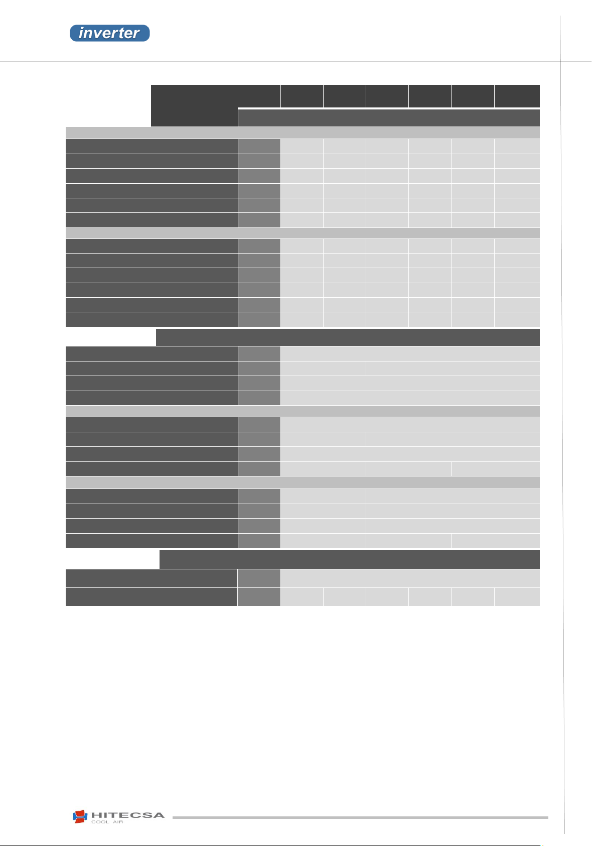
MOSAIC HE RANGE
35i
40i
45i
55i
70i
80i
ACVIBA HE
CAPACITIES
Max. cooling capacity (120 Hz)
(1)
kW
35.3
41.0
45.7
56.1
70.7
82.3
Total absorbed power input (120 Hz)
(2)
kW
15.1
20.9
17.7
23.8
30.1
41.7
Min. cooling capacity (20 Hz)
(1)
kW
7.3
9.6
2.4
5.8
7.3
9.6
EER (120 Hz)
-
2.35
1.96
2.59
2.36
2.35
1.98
Seasonal coefficient SEER
(3)
%
4.68
4.13
4.44
4.41
4.65
4.09
Seasonal performance (ηs,c)
(3)
-
184.3
162.3
174.6
173.4
183.1
160.5
Max. heating capacity (120 Hz)
(4)
kW
30.3
35.3
41.2
48.8
60.7
70.2
Total absorbed power input (120 Hz)
(2)
kW
10.2
12.9
12.6
16.2
20.4
25.7
COP (120 Hz)
2.97
2.74
3.26
3.01
2.97
2.73
Min. heating capacity (20Hz)
(4)
kW
6.5
7.7
3.7
4.8
6.5
7.7
Seasonal coefficient SCOP
(3)
3.33
3.21
3.38
3.21
3.37
3.23
Seasonal performance (ηs,h)
(3)
%
130.1
125.3
132.2
126.2
131.7
126.4
REFRIGERATION CIRCUIT
Refrigerant type
R-410A
Number of circuits
1
2
Power stages
Variable
Global Warming Potential (GWP)
(5)
2088
CIRCUIT 1
Compressor type
Scroll - BLDCM
Number of compressors
1
1
Oil type
PVE - FV50S
Oil volume L 2.3
1.7
2.3
CIRCUIT 2
Compressor type
-
Scroll - BLDCM
Number of compressors
-
1
Oil type -
PVE - FV50S
Oil volume L -
1.7
2.3
ELECTRICAL SPECIFICATIONS
Power supply
V / ~ / Hz
400 / 3+N /50
Max. operation current
A
33
49
55
68
66
99
TECHNICAL SPECIFICATIONS
(1).
Calculated according to the UNE-EN-14511 standard, for indoor temperature conditions of 27ºC B.S. / 19ºC B.H. and 35ºC
outdoor temperature. Frequency of the compressor as stated above.
(2).
Nominal consumption of the entire equipment (compressors and fans) in nominal conditions, calculated according to the EN-
14511 standard.
(3).
The seasonal coefficient for the cooling season (SEER) or the heating season (SCOP) has been calculated according to the EN-
14825 standard.
The seasonal area cooling performance ratio (ηs,c) has been calculated according to the (EU) 2281 regulation.
(4).
Nominal heating capacity calculated according to the UNE-EN-14511 standard for indoor temperature of 20ºC and outdoor
temperature of 7ºC B.S. / 6ºC BH. Frequency of the compressor as stated above.
(5).
GWP: Global warming potential (climatic) of 1 kg of greenhouse gas for 1 kg of CO2, calculated over a period of 100 years.
9
Page 10
IOM_ACVIBA HE_35ia80i_207910_190501_EN
ACVIBA HE
AIR-AIR PACKAGED UNITS
COMPACT VERTICAL INVERTER
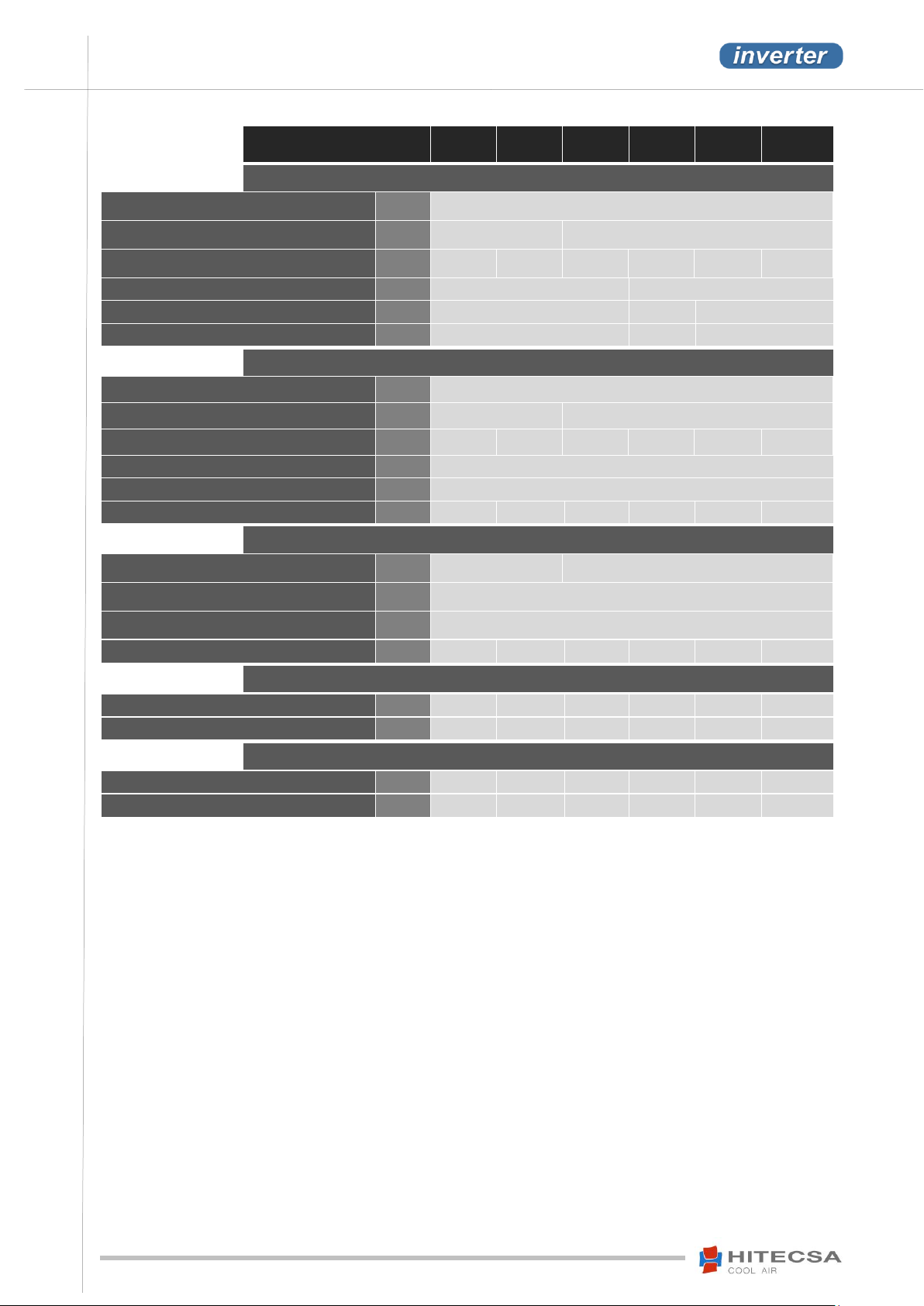
MOSAIC HE RANGE
35i
40i
45i
55i
70i
80i
INDOOR FAN
Type
Plug fan EC
Total number 1
2
Nominal airflow
m³/ h
6,500
8,500
9,600
11,000
13,000
17,000
Available pressure according to standard
(1)
Pa
150
200
Available static pressure (Nominal flow)
Pa
500
450
500
Available high pressure
(2)
(Max. flow)
Pa
1000
900
1000
OUTDOOR FAN
Type
Plug fan EC
Total number 1
2
Max. airflow
m³/ h
13,000
15,000
18,400
22,000
26,000
30,000
Available pressure according to standard
(1)
Pa
60
Available static pressure (Max. flow)
Pa
Up to 60 Pa
Available high pressure
(2)
(Max. flow)
Pa
250
200
550
550
250
200
DIMENSIONS AND WEIGHT
Length
mm
1,423
2,800
Width
mm
854
Height
mm
2,491
Weight
kg
517
523
972
972
1007
1024
SOUND POWER LEVEL (Lw)
Exterior radiation Standard unit
dBA
86.5
90.8
74.6
85.3
89.2
93.7
Exterior radiation Unit running at 50%
(4)
dBA
83.0
82.1
64.4
72.5
86.0
86.0
SOUND PRESSURE LEVEL at 5 m
(3)
(Lp)
Exterior radiation Standard unit
dBA
65.1
69.4
53.1
63.8
67.7
72.3
Exterior radiation Unit running at 50%
(4)
dBA
61.5
60.6
43.0
51.1
64.6
64.6
TECHNICAL SPECIFICATIONS
(1)
According to the EN 14511 standard.
(2)
Option
(3)
Directivity = 2 (in semi-sphere)
(4)
The unit is running with the fan at the 2nd speed level with a partial charge of 50% of its capacity.
10
Page 11
ACVIBA HE
AIR-AIR PACKAGED UNITS
COMPACT VERTICAL INVERTER
IOM_ACVIBA HE_35ia80i_207910_190501_EN
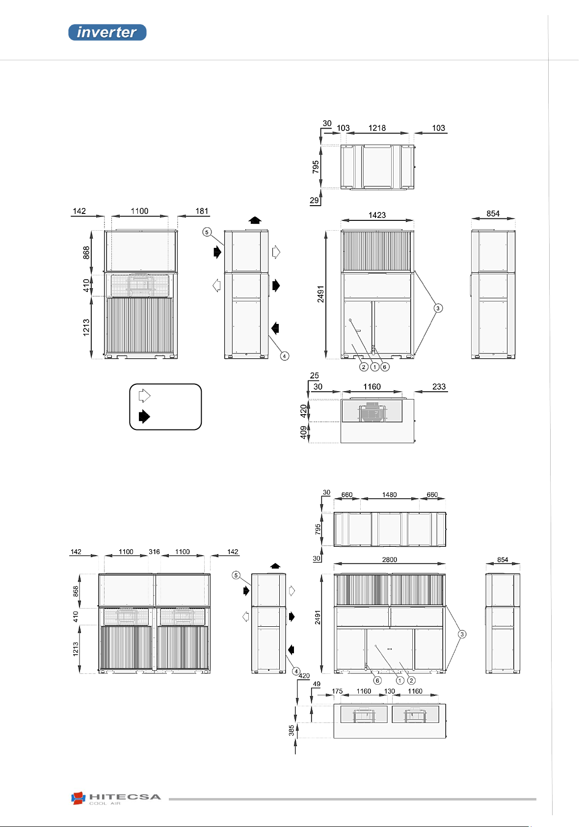
1. Main switch
2. Electrical box
3. Drainage ¾”
4. Outdoor coil
5. Indoor coil
6. Electrical connection plug
Option
Standard
DIMENSIONS
ACVIBA HE 35i – 40i
Units with 1 circuit
ACVIBA HE 45i – 80i
Units with 2 circuits
11
Page 12
IOM_ACVIBA HE_35ia80i_207910_190501_EN
ACVIBA HE
AIR-AIR PACKAGED UNITS
COMPACT VERTICAL INVERTER
1. Compressor
2. 4-way valve
3. Electronical expansion valve (EEV)
4. Check valve
5. Filter
6. Liquid container
9. Outdoor coil
10. Outdoor fan
11. Indoor coil
12. Indoor fan
HP. High pressure switch
PT. Pressure transductor
TD. Discharge temperature
TE. Outdoor air temperature
TI. Supply air temperature
TS. Temperature probe
VS. Security valve
OPTIONS:
8. Suction accumulator
REFRIGERATION DIAGRAM
ACVIBA HE 35i – 40i
Units with 1 circuit
12
Page 13
ACVIBA HE
AIR-AIR PACKAGED UNITS
COMPACT VERTICAL INVERTER
IOM_ACVIBA HE_35ia80i_207910_190501_EN
1. Compressor
2. 4-way valve
3. Electronical expansion valve (EEV)
4. Check valve
5. Filter
6. Liquid container
9. Outdoor coil
10. Outdoor fan
11. Indoor coil
12. Indoor fan
HP. High pressure switch
PT. Pressure transductor
TD. Discharge temperature
TE. Outdoor air temperature
TI. Supply air temperature
TS. Temperature probe
VS. Security valve
OPTIONS:
8. Suction accumulator
REFRIGERATION DIAGRAM
ACVIBA HE 45i – 80i
Units with 2 circuits
13
Page 14
IOM_ACVIBA HE_35ia80i_207910_190501_EN
ACVIBA HE
AIR-AIR PACKAGED UNITS
COMPACT VERTICAL INVERTER
35i
40i
1
129
130
2
135
137
3
129
131
4
124
125
TOTAL
517
523
45i
55i
70i
80i
1
233
233
244
250
2
238
238
248
254
3
253
253
260
262
4
248
248
255
258
TOTAL
972
972
1007
1024
TRANSPORT
INSPECTION AT RECEPTION
It is advisable to examine the equipment carefully upon reception.
Check that the equipment has not been damaged during transport and that it is complete with all the parts
specified in the order and/or the options stated in the order. If this is not the case please contact the transport
company immediately (within 48h).
Verify the correct voltage of the nameplate and make sure it is in accordance with local power supply.
In case of any flaw or anomaly detected, please contact HITECSA.
WEIGHT DISTRIBUTION (kg)
14
Page 15
ACVIBA HE
AIR-AIR PACKAGED UNITS
COMPACT VERTICAL INVERTER
IOM_ACVIBA HE_35ia80i_207910_190501_EN
TRANSPORT
RIGGING
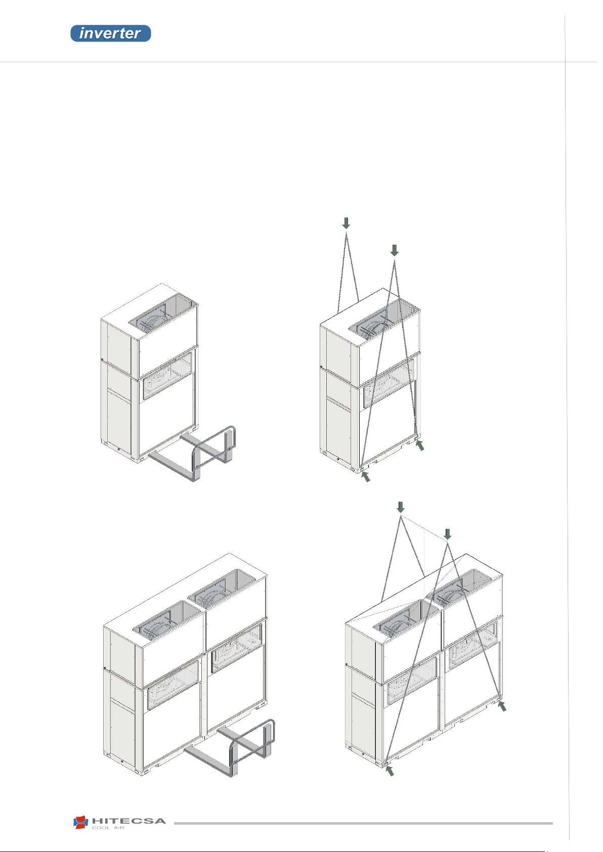
Before moving the unit, make sure that all panels are fixed properly.
Raise and put the equipment down carefully.
Do not tilt the unit more than 15 degrees during transportation.
Always transport the unit in its original packaging to the place of installation.
All units come with a particular rigging diagram of that model similar to the one shown below. Be sure to hoist
the machine through the points indicated in the diagram.
Make sure that the unit is balanced, stable and without any deformations during lifting operations.
ACVIBA HE 35i – 40i
ACVIBA HE 45i – 80i
15
Page 16
IOM_ACVIBA HE_35ia80i_207910_190501_EN
ACVIBA HE
AIR-AIR PACKAGED UNITS
COMPACT VERTICAL INVERTER
The warranty will not cover any damage caused frozen water.
WARNING
TRANSPORT
STORAGE
If the equipment is going to be stored before the installation, please follow the following instructions in order to avoid
damages, corrosion or deterioration:
Move it carefully.
Do not place the machine in places exposed to ambient temperatures above 50ºC and preferably keep the unit away
from direct sunlight.
The sun radiation may cause a very high temperature increase that can make the refrigerant pressure reach such high
levels that the security valves would be activated.
1. Moreover, when temperatures decrease water condensation may occur inside the machine or between the machine
and the plastic wrap.
Avoid placing objects on top of the unit (unless this is permitted according to the drawings or the overlap diagrams
indicated on the packaging, etc. Follow these indications).
In case of prolonged storage before installation avoid the penetration of water, dust and objects in general caused by
invasion or biological, meteorological and/or human impacts.
Minimum storage temperature: -10ºC.
2. If some components contain water, it is compulsory to empty them or to add an antifreeze solution to make sure that
the freezing point will always be lower than the ambient temperature.
Maximum relative humidity: 90%.
16
Page 17
ACVIBA HE
AIR-AIR PACKAGED UNITS
COMPACT VERTICAL INVERTER
IOM_ACVIBA HE_35ia80i_207910_190501_EN
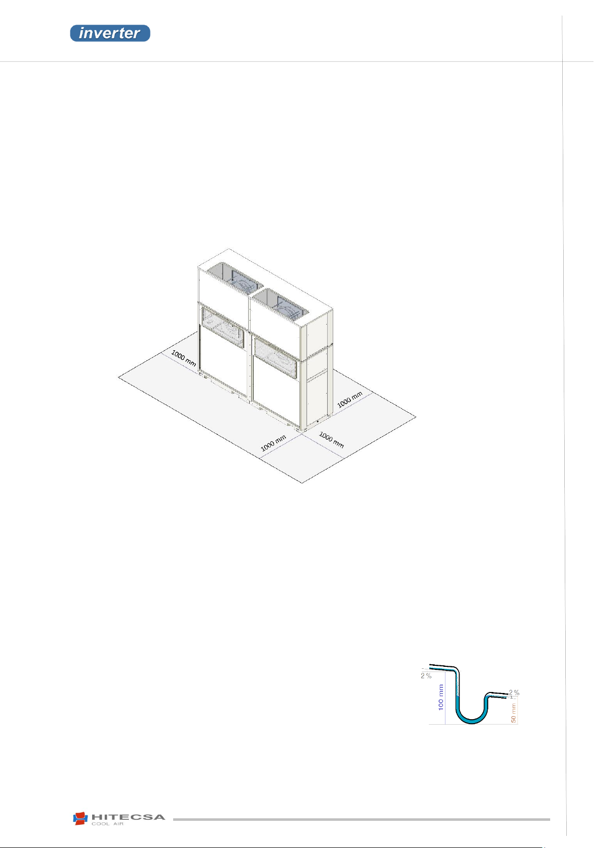
Recommended dimensions
INSTALLATION
INSTALLATION SITE
Read and comply with the local rules and regulations applying to the installation of air conditioning systems.
Choose a clean place without dust nor debris.
Respect the allocated service area prepared for the equipment.
Verify that the ground or the structure prepared for the equipment is strong enough to support its weight during
operation.
Install shock absorbers throughout the installation to prevent the transmission of noise and vibration.
Check that the direction of the sound level will not annoy anybody.
The standard version of this equipment has been designed for installation inside a building (with a roof). It is not
prepared for installation outside. Please check with Hitecsa if you plan to expose the machine to weather conditions.
SERVICE AREA (mm)
UNIT SETTLEMENT
Make sure that the unit is slightly inclined (~2%) following the direction of the drains.
The bed frame shall be big enough and strong enough to support the unit weight.
DRAINAGE
All the drain devices are prepared with a male 3/4” gas connection (ISO 228-1, BSPP).
The unit is equipped as a standard feature with a condensate drain tray to avoid an excessive water accumulation in
the indoor side and the outdoor side.
The condensate drain pipe diameter shall be equal or larger than the unit connection depending on its length and
inclination.
If the drain line is exposed to air temperatures lower than 0 degree, it is necessary to cover it with thermal insulation
material or to use electrical heating devices to prevent water from freezing that would entail tube damage.
The drainage line shall be inclined by 2% minimum for proper water evacuation.
It is convenient to install a drain trap with proper dimensions (see diagram) or a
draining system with a condensate pump to avoid excessive water accumulation
in the indoor side and the outdoor side.
17
Page 18
IOM_ACVIBA HE_35ia80i_207910_190501_EN
ACVIBA HE
AIR-AIR PACKAGED UNITS
COMPACT VERTICAL INVERTER
ACVIBA HE
35i
40i
45i
55i
70i
80i
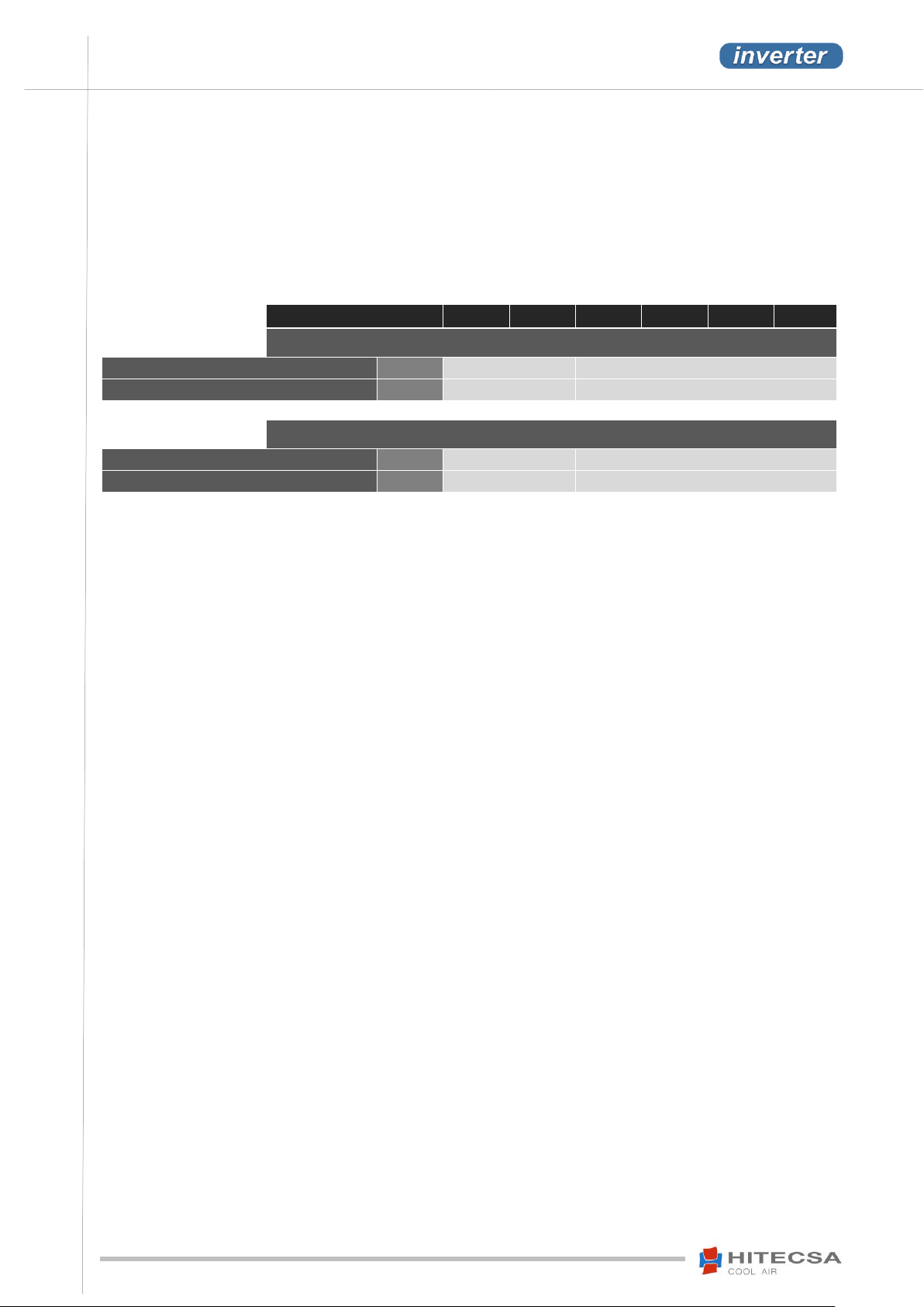
AIR DUCTS – INDOOR SECTION
Supply ducts
Install 1
Install 1 or 2
Return ducts
Install 1
Install 1 or 2
AIR DUCTS – OUTDOOR SECTION
Supply ducts
Install 1
Install 1 or 2
Return ducts
Install 1
Install 1 or 2
INSTALLATION
AIR DUCTS
The air duct dimensions will be determined according to the air flow and the available static pressure of the units.
They shall be designed by qualified technicians. An incorrect design may reduce the unit’s performance and may be
a hindrance when access to the unit for maintenance operations is needed (in particular where there is only one
possible access).
Use ducts made of non-inflammable material in order to avoid any risk of fire as a consequence of the deflagration of
gases. It is advisable to use insulated metal ducts.
Use flexible conduits to connect air ducts to the unit so as to avoid vibration and noise transmission.
18
Page 19
ACVIBA HE
AIR-AIR PACKAGED UNITS
COMPACT VERTICAL INVERTER
IOM_ACVIBA HE_35ia80i_207910_190501_EN
ACVIBA HE
35i
40i
45i
55i
70i
80i
MOSAIC HE RANGE
ELECTRICAL SPECIFICATIONS
Power supply
V / ~ /Hz
400V / 3 Phases + Neutral / 50 Hz.
Max. current
A
33
49
55
68
66
99
Starting current
A
38
54
55
68
76
109
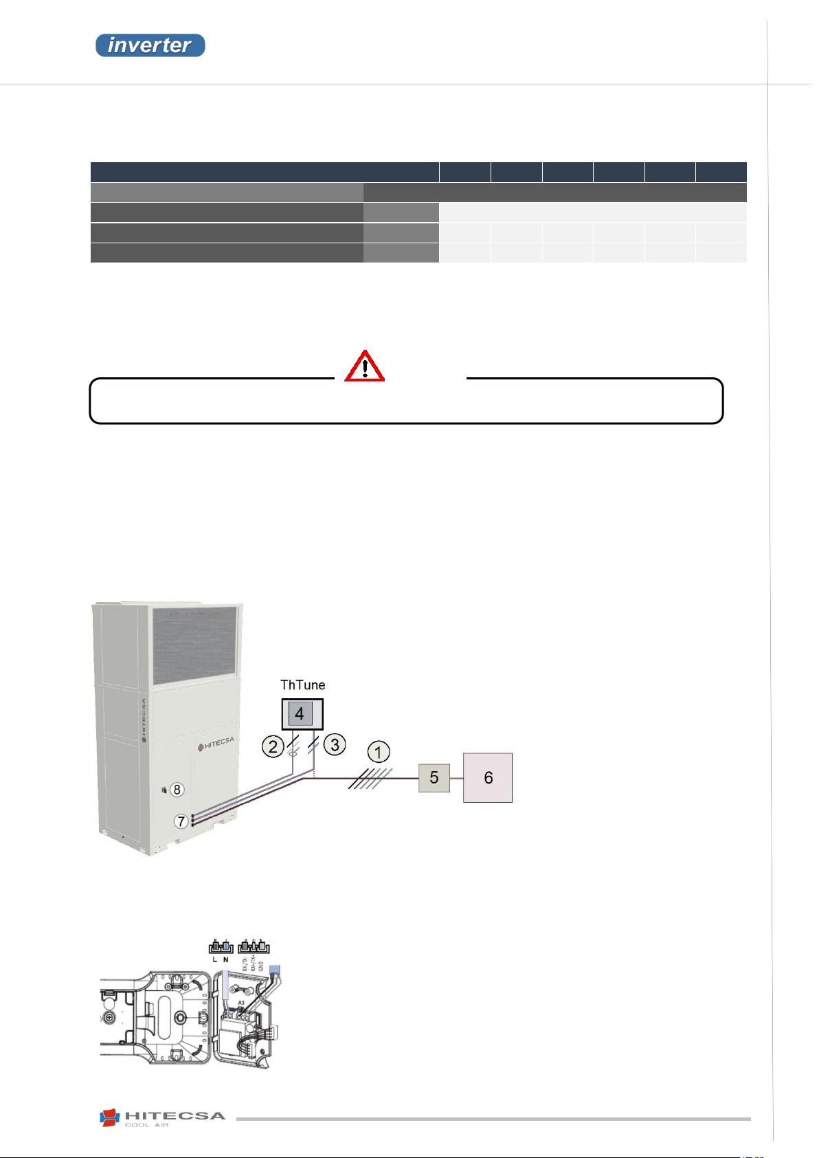
2 wire power supply cable, 230 VAC (L+N)
Control cable, one twisted and shielded pair AWG 20/22 with a drain wire to
GND.
Keep a minimum distance of 15 cm between the control/communication cable
and the 230V power supply cable outside the unit.
WARNING
1. 5 wire supply 400V/3/50Hz (Three-phase + Neutral + Earth)
2. Control cable, twisted and shielded AWG20/22 with drain wire to GND
3. 2 wire power cable 230V 50/60Hz (Phase + Neutral)
The power supply can be either external or coming from the unit.
4. Th Tune remote control (Do not mix the power cables with the control
cables).
5. Time delay fuses or circuit breakers curve D.
6. Main switch of the installation.
7. Cable outlets (The position may vary depending on the model)
8. Main switch of the unit (The position may vary depending on the model)
INSTALLATION
ELECTRICAL INSTALLATION
ELECTRICAL SPECIFICATIONS
The power supply of the unit shall correspond to the required power supply stated on the unit name plate.
The unit is equipped with frequency inverters. A 300mA differential switch or a superimmunized switch shall be installed
to avoid unprogrammed discharges.
ELECTRICAL CONNECTIONS
Before proceeding to any operation disconnect the unit from the power supply.
The unit power supply shall be within 10% of volts indicated on the unit nameplate. Damage caused by the start-up
of the unit with an incorrect voltage line will not be covered by the Hitecsa’s warranty.
Always refer to the unit wiring diagram when completing electrical connections.
The electrical wiring connections and the line protection devices must be installed by the installer according to the
current local laws that apply to the installation site.
The interconnecting wires shall be protected in a tube or an electrical cable conduit, cable tray, etc..
THERMOSTAT CONNECTION
The serial thermostat model is Th Tune. It is a user interface provided with a room temperature probe.
Connection of Th TUNE
19
Page 20
IOM_ACVIBA HE_35ia80i_207910_190501_EN
ACVIBA HE
AIR-AIR PACKAGED UNITS
COMPACT VERTICAL INVERTER
INSTALLATION
Connection of the Th TUNE in units with 1 circuit
Connected to the main controller
Connection of the Th TUNE in units with 2 circuits
Connected to the secondary control board, serial feature with the main controller (Master).
CONNECTION OF THE PGD1 or the Mini PGD controllers (options)
Always connected to the main controller.
CONNECTION of the wall probe (option)
The remote room probe is a NTC thermal resistance placed within a box and connected with 2
copper wires of 0.5mm² to 1,5mm² thickness (the longer the distance is the thicker the wire will
be).
(Refer to the electrical diagram).
20
Page 21

ACVIBA HE
AIR-AIR PACKAGED UNITS
COMPACT VERTICAL INVERTER
IOM_ACVIBA HE_35ia80i_207910_190501_EN
OPERATION
BEFORE START-UP
The installer shall complete various control operations to make sure that the unit operation is correct when commissioning
the unit for the first time. Start-up shall be supervised by an air conditioning qualified technician.
GENERAL INSTALLATION CHECKING
Control that there is space enough for operation, access to the electrical box and for maintenance.
Control that the unit is inclined with 2% following the drain direction.
Control that all the panels are fitted properly with screws.
Control the condition and position of the grilles, diffusers, air ducts, etc…
Control that the air filters are clean and correctly fitted.
Control that the drainage is not blocked.
Electrical installation checking
Check that the electrical wiring diagram is available as it is an essential document to complete the connection
operations.
Check that all the electrical connections are tight.
Check the power supply voltage. The power supply to the unit must be within 10% of the voltage level stated on
the serial plate. In case of three-phases lines, make sure that the three phases are well balanced. Damages
caused by the start-up of the unit with an incorrect voltage line will not be covered by the Hitecsa’s warranty.
Check that the necessary line protection devices are installed and comply with the local valid legislation.
The unit is equipped with frequency converters. Check that the main switch is of minimum 300 mA or is a
superimmunized switch so as to avoid possible power cuts caused when it is activated.
Check that the thermostat is connected and power supplied properly.
Check the remote on/off connection.
Check the rotation direction of the fans.
Check that the electrical interconnecting cables are protected with a tube or a conduit.
21
Page 22
IOM_ACVIBA HE_35ia80i_207910_190501_EN
ACVIBA HE
AIR-AIR PACKAGED UNITS
COMPACT VERTICAL INVERTER
OPERATION
START-UP
Make sure you have access to measuring instruments with their up-to-date calibration certificates.
Thermometer, anemometer, voltmeter, hook-on meter, high and low manometer.
The person/people who will complete the measuring operations or the ones who will participate in the start-up
process must be qualified professionals with the valid certification according to the local regulation.
Please read all the security precaution guidelines.
Before using a hook-on meter make sure that the cable or the cables are connected properly. To disconnect a cable
by using force may damage the equipment and entail people injuries.
It is necessary to register the air inlet and outlet temperatures to the internal coil, the volts and amps of the
compressor and motor fan, as well as the suction and discharge pressure of each compressor.
Remember that it is necessary to clean the air filters after the first 4 hours of operation.
Complete at least 3 cooling cycle operations.
Indoor fan start-up:
- Do not approach the fan while it is rotating even at a very slow rotation speed!
- Beware automatic restart!
The fan / motor may start and stop automatically for functional reasons.
After a power cut or a technical failure the fan will restart as soon as voltage is present again!
- ROTATION CAUSED BY AIR FLOW IN THE WRONG DIRECTION.
If you switch the fan on while it is rotating in the opposite direction the control will reduce the rotations until it
reaches the ‘0’ value (fan stoppage). Then, the control will make a restart in the correct rotation direction.
The higher the number of rotations in the wrong direction, the longer time the control will need to make the fan
stop. If the fan is rotating heavily in the wrong direction the control may not be able to start the fan in the correct
direction.
Do not switch the fan off and restart it again to slow it down!
22
Page 23
ACVIBA HE
AIR-AIR PACKAGED UNITS
COMPACT VERTICAL INVERTER
IOM_ACVIBA HE_35ia80i_207910_190501_EN
OUTDOOR air temperature
INDOOR air temperature
COOLING CYCLE
Dry
Humid
Dry
Humid
Minimum
-15ºC *
-
21ºC
15ºC
Maximum
55ºC - 31ºC
23ºC
HEATING CYCLE
Dry
Humid
Dry
Humid
Minimum
-12ºC
-13ºC
16ºC
-
Maximum
24ºC
18ºC
24ºC
-
Return air temperature (oC)
Return air temperature (oC)
Outdoor temperature (
o
C)
Return air
temperature (
o
C)
OPERATION
OPERATION LIMITS
Cooling Mode
Heating Mode o
Please contact Hitecsa for changes of the controller adjustment.
These units can be running at a maximum altitude of 1500 m above sea level with a performance loss lower than 3%.
They have been designed to work with 100% of recycled air. An installation with 100% of outdoor air is prohibited.
23
Page 24
IOM_ACVIBA HE_35ia80i_207910_190501_EN
ACVIBA HE
AIR-AIR PACKAGED UNITS
COMPACT VERTICAL INVERTER
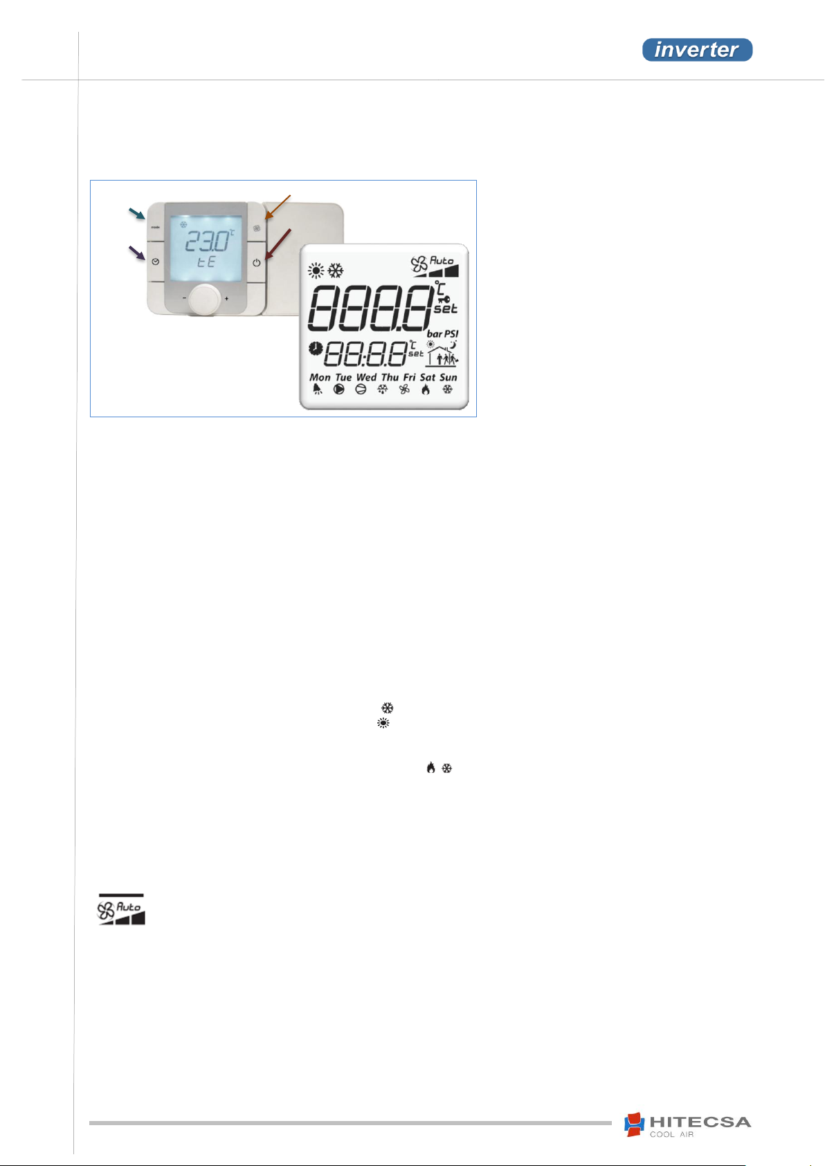
- LCD backlighted display.
- Two alphanumeric strings of 4
characters.
- Complete set of symbols to obtain all
the information about the operation
simultaneously in the same display.
- Central multifunctional button: turn to
move through the menus or
increase/decrease a value and press
to introduce or select.
Mode
Clock
Fan (non-operative)
On /Off
OPERATION
TH TUNE CONTROLLER
Display:
Start / Stop
Press and hold the (On / Off) button for two seconds to turn the thermostat on or off. The word "OFF" will be shown on
the thermostat display when it is off.
NOTE: The thermostat will show "OFFd" if the remote On-Off contact is open and “OFFs” when it is stopped from the
Modbus.
Setpoint Temperature Adjustment
Adjust the SETPOINT temperature by turning the center button.
Calibration of the Th-Tune internal temperature probe
Use a correction value, positive or negative, that shall be added to the value of the probe. A value equal to zero will not
change the value of the probe.
Press the FAN + ON/OFF keys and keep them pressed until a password is required.
Enter password “22” and press for log in. Turn the central button until the option PCAL is displayed and select.
Turn the central button to modify the correction value and press for validation.
Operation modes
Press the (Mode) button to scroll through the available operation modes.
Available Operation Modes:
- Cooling mode – The display will show the icon:
- Heating mode – The display will show the icon: This mode is not available for the Cooling Only units.
- Automatic mode – The display will show “Auto”. This mode is not available for the Cooling Only units. The operating
mode will change between cool and heat depending on the selected temperature Set-point. The currently active mode
will be shown on the lower right corner of the thermostat: .
This mode SHALL NOT be selected with units that are not provided with the condensation control option as it could
cause the failure of the equipment when activating the cooling mode with very low outdoor temperatures.
Indoor Fan Modes:
“Fan / Autofan” with “Auto” or continuous ventilation
- With automatic fan – The Display icon will show "Auto".
The fan works only when there is request for cool or heat in the automactic mode.
24
- Continuous ventilation – The “Auto” icon is not displayed.
The fan Works when there is a request for cool or heat in the automatic mode and when there is no
request of low speed.
Page 25
ACVIBA HE
AIR-AIR PACKAGED UNITS
COMPACT VERTICAL INVERTER
IOM_ACVIBA HE_35ia80i_207910_190501_EN
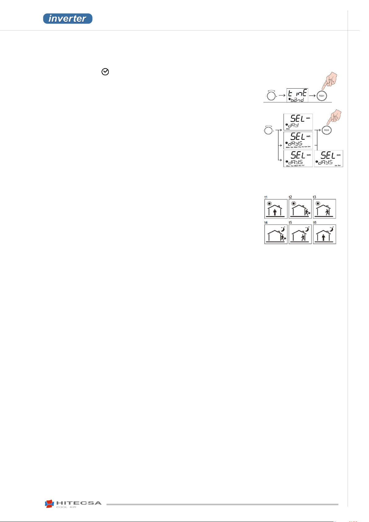
- Keep the button “ ” pressed during 3 seconds minimum until “Cloc” appears (if
the stated hour is not correct you can change it here): turn the central button and
chose “Time band” or select “Esc” to leave.
- In general so as to move through the different displays, turn the central button
and select by pressing it.
Turn the central button to select the desired schedule type:
- Select if you want a different schedule day by day, the same schedule for all week
(displays all days) or one from Monday to Friday and other from Saturday to
Sunday. Press the central button to select the desired day or days.
By turning the button you can select 6 different displays that correspond to 6
different moments of the day (see displays).
- A temperature set-point is set for each display if you want the unit to be operating
or we program “OFF” if we want it to be stopped. We set the hour when it will be
activated. If we select “--:--“ instead of an hour, the display will be deprogrammed
and it will not activate.
- The hour that we can select for each display will always be greater than the hour
of the previous display.
- It is not possible to modify the operation mode.
- Press ESC display to exit.
- The icons on the display are meant as guide symbols only and the user can select
the hours according to his personal needs.
- After the final time section (t6) the next one will be t1 the following day.
OPERATION
TH TUNE CONTROLLER
Time schedule
Examples of time schedule:
Full (working) day Schedule from 9:00am to 9:00pm
t1: Start, “8:45”
t2, t3: without programming, “--:--“
t4: stop, “20:00”
t5, t6: without programming, “--:--“
Split shift schedule 9:00-13:00 and 16:00-20:00
t1: Start, “8:45”
t2: Stop because of midday absence or reduction to a
cheaper set-point.“13:00”
t3: Start or back to the normal set-point because presence.
“16:00”
t4: Stop. End of the day. “20:00”
t5, t6: without programming, “--:--“
Domestic schedule
t1: start, “7:00”
t2: Stop because of absence or decrease to a cheaper setpoint. “8:30”
t3: Start or back to the normal set-point “13:15”.
t4: Stop because of absence or decrease to a cheaper setpoint. “15:30”
t5: Start or back to the main set-point.
t6: Night stop or back to a cheaper set-point. “13:00”
25
Page 26
IOM_ACVIBA HE_35ia80i_207910_190501_EN
ACVIBA HE
AIR-AIR PACKAGED UNITS
COMPACT VERTICAL INVERTER
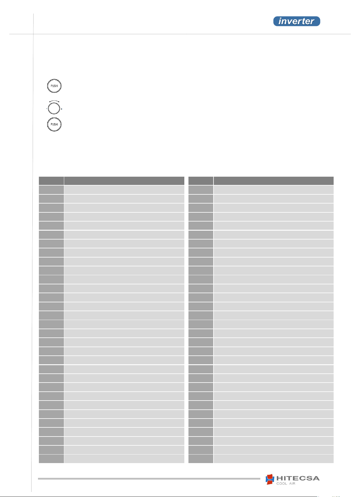
Press several times the central button until ‘RES’
is displayed (only available when there is at least
one active alarm).
All the alarms are cancelled once their causes
have disappeared or when they have been
solved.
Turn the central button to go from 0 to 1.
Press the central button one time to confirm.
When the reset is completed, the text will
change to OK.
Alarm
Description
bt11
Probe U1 P.Condenser
bt13
Probe U2 P.Condenser
bt16
Probe U3 P.Condenser
bt12
Probe U4 P.Condenser
bt15
Probe U5 P.Condenser
bp12
Probe U6 P.Condenser
bp11
Probe U7 P.Condenser
bt14
Probe U8 P.Condenser
bt22
Probe U9 P.Condenser
bh16
Probe U10 P.Condenser
bP22
Probe U11 P.Condenser
bP21
Probe U12 P.Condenser
PA17
High pressure critical C1
Pb17
Low pressure critical C1
Pn17
Min. pressure critical C1
PA27
High pressure critical C2
Pb27
Low pressure critical C1
Pn27
Min. pressure critical C1
bt57
Alarm Probe t TH TUNE
bh57
Alarm Probe HR TH TUNE
SC00
TH TUNE Clock
dF01
Dirty filter 1
dF02
Dirty filter 2
EE10
Alarm Low SH C1 Ext
EE11
Alarm LOP C1 Ext
EE12
Alarm MOP C1 Ext
EE13
Low Suct C1 Ext
EE14
EVOTunes C1 Ext
EE05
HitCond EXT
EE20
Alarm Low SH C2 Ext
EE21
Alarm LOP C2 Ext
Alarm
Description
EE22
Alarm MOP C2Ext
EE23
Low Suct C2 Ext
EE24
EVOTunes C2 Ext
u100
Al_offline inverter C1
u101
Al_Inv_Overcurrent C1
u102
Al_Inv_motor_overload C1
u103
Al_Inv_Overvoltage C1
u104
Al_Inv_Undervoltage C1
u105
Al_Inv_Drive_OverT C1
u106
Al_Inv_Drive_UnderT C1
u107
Al_Inv_Overcurrent_HW C1
u108
Al_Inv_Reserved1 C1
u109
Al_Inv_Reserved2 C1
u110
Al_Inv_Cpu_error C1
u111
Al_Inv_Param_default C1
u112
Al_Inv_DCbus_ripple C1
u113
Al_Inv_Datacoms_Fault C1
u114
Al_Inv_Error_thermistor C1
u115
Al_Inv_Reserved3 C1
dP11
Al_Inv_Reserved4 C1 => Pressure switch C1
u117
Al_Inv_Motor_phase C1
u118
Al_Inv_Reserved5 C1
u119
Al_Inv_Speed_fault C1
u120
Al_Inv_PFC_Module_error C1
u121
Al_power_sup_overvolt C1
u122
Al_power_sup_undervolt C1
u123
Al_Inv_Reserved6 C1
u124
Al_Inv_Reserved7 C1
u125
Al_ground_fault C1
u126
Al_cpu_sync_err1 C1
u127
Al_cpu_sync_err2 C1
OPERATION
TH TUNE CONTROLLER
Alarms
The alarms shown by a code on the thermostat will cause the stoppage of the unit.
Reset of the alarm codes
After resetting is completed the thermostat will automatically go back to its normal state and the room or return air
temperature depending on the configuration will be displayed.
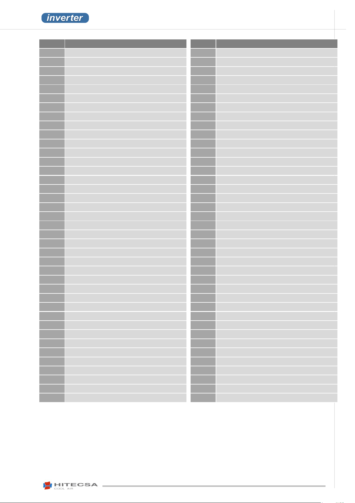
DIAGNOSIS OF THE ALARMS
TH TUNE - Description of the alarm codes
26
Page 27
ACVIBA HE
AIR-AIR PACKAGED UNITS
COMPACT VERTICAL INVERTER
IOM_ACVIBA HE_35ia80i_207910_190501_EN
Alarm
Description
u128
Al_drive_overload C1
u129
Al_Inv_Reserved8 C1
u130
Al_Unexpected_Inv_Stop C1
u200
Al_offline inverter C2
u201
Al_Inv_Overcurrent C2
u202
Al_Inv_motor_overload C2
u203
Al_Inv_Overvoltage C2
u204
Al_Inv_Undervoltage C2
u205
Al_Inv_Drive_OverT C2
u206
Al_Inv_Drive_UnderT C2
u207
Al_Inv_Overcurrent_HW C2
u208
Al_Inv_Reserved1 C2
u209
Al_Inv_Reserved2 C2
u210
Al_Inv_Cpu_error C2
u211
Al_Inv_Param_default C2
u212
Al_Inv_DCbus_ripple C2
u213
Al_Inv_Datacoms_Fault C2
u214
Al_Inv_Error_thermistor C2
u215
Al_Inv_Reserved3 C2
dP21
Al_Inv_Reserved4 C2 => Pressure switchC2
u217
Al_Inv_Motor_phase C2
u218
Al_Inv_Reserved5 C2
u219
Al_Inv_Speed_fault C2
u220
Al_Inv_PFC_Module_error C2
u221
Al_power_sup_overvolt C2
u222
Al_power_sup_undervolt C2
u223
Al_Inv_Reserved6 C2
u224
Al_Inv_Reserved7 C2
u225
Al_ground_fault C2
u226
Al_cpu_sync_err1 C2
u227
Al_cpu_sync_err2 C2
u228
Al_drive_overload C2
u229
Al_Inv_Reserved8 C2
u230
Al_Unexpected_Inv_Stop C2
dt13
Thermal Vint C1
dt24
Thermal Vint C2
dt16
Thermal Vext C1
dt27
Thermal Vext C2
dh00
Smoke detector
Alarm
Description
bt09
Indoor air Quality Probe.
bt13
Air supply Probe
bt22
temp. C2 int.
bt12
Evaporation temp. C1 int.
bt14
return temp. int.
bP12
Evaporation pres. C1 int.
bP22
Evaporation pres. C2 int.
bh07
Indoor humidity Probe
Ei13
Low Suct C1 Int
Ei23
Low Suct C2 Int
Ei10
Alarm Low SH C1 Int
Ei20
Alarm Low SH C2 Int
Ei11
Alarm LOP C1 Int
Ei21
Alarm LOP C2 Int
Ei12
Alarm MOP C1 Int
Ei22
Alarm MOP C2 Int
Ei14
EVOTunes C1 Int
Ei24
EVOTunes C2 Int
Ei05
HitCond Int
td11
High t.Discharge c1
PE11
Low delta pres.C1
PE15
start compressor C1
PE16
al.envelope c1
td21
High t.Discharge c2
PE21
Low delta pres.C2
PE25
start compressor C2
PE26
al.envelope c2
SS00
Alarm Evaporation unit disconnected
nc11
Alarm hour counter comp. C1
nc21
Alarm hour counter comp. C2
nu11
Alarm hour counter VI. C1
nu21
Alarm hour counter VI. C2
nE11
Alarm hour counter VE. C1
nE21
Alarm hour counter VE. C2
PF11
Alarm leakage C1
PF21
Alarm leakage C2
oF00
off digital inlet
oS00
off supervision
on00
off manufacturer
27
Page 28
IOM_ACVIBA HE_35ia80i_207910_190501_EN
ACVIBA HE
AIR-AIR PACKAGED UNITS
COMPACT VERTICAL INVERTER
Type of
failure
Possible cause
Solution
Fan does
not run
(anymore)
Failure line voltage. Failure of one phase.
Under – or overvoltage.
Check line voltage.
Earth fault.
Check motor connection and line voltage.
Short circuit winding.
Replace fan.
The thermal protection of the motor has
triggered (motor is overheated)
Check for free air way; remove foreign bodies if necessary "Impeller
blocked or dirty". Check temperature of supply air. Check voltage.
Impeller blocked or dirty
Switch off power to the motor and secure against switching back
on.
Check safe isolation from supply.
Remove safety grille.
Remove foreign bodies or soiling.
Remount the safety grille.
Fan will not
start
Temperature too low for bearing grease.
Insert bearing with cold greasing.
Air stream wrong direction (Motor turns in
wrong direction at high speed)
Check air stream.
In case of very strong air stream, the fan might not be able to start.
Fan turns
too slowly
Impeller / blade scrapes / brushes.
When indicated clear foreign bodies / dirt from the fan.
Active temperature management effective
(Motor or electronics over-heated).
Check for free air ways; remove foreign bodies if necessary. "Impeller
blocked or dirty". Check temperature of supply air. Check installation space
(air speed overheat sink).
Air flow too
low
Fan turns too slowly
Check “Fan turns too slowly”.
Airways blocked
Check for free air ways (supply/exhaust air vents, filters) “Impeller blocked
or dirty”
Pressure loss different to planned.
Check fan selection.
Vibrations
Imbalance.
Check blades for damage, soiling or ice. “Impeller blocked or dirty”
No or wrong vibration dampers (only in
radial)
Install correct vibration dampers
Unusual
noises
Bearing damaged / worn.
Change bearings.
With the motor size 055“(Z” / “B” with cross flow), replace the fan.
Impeller / blade scrapes / brushes.
When indicated clear foreign bodies / dirt from the fan. “Impeller blocked or
dirty”
Operation beyond stall point (for axial fans)
Check for free air ways (supply / exhaust air vents, filters)
Wrong overlap on nozzle ( for centrifugal
fans)
Observe the installation instructions.
OPERATION
EC motor fans
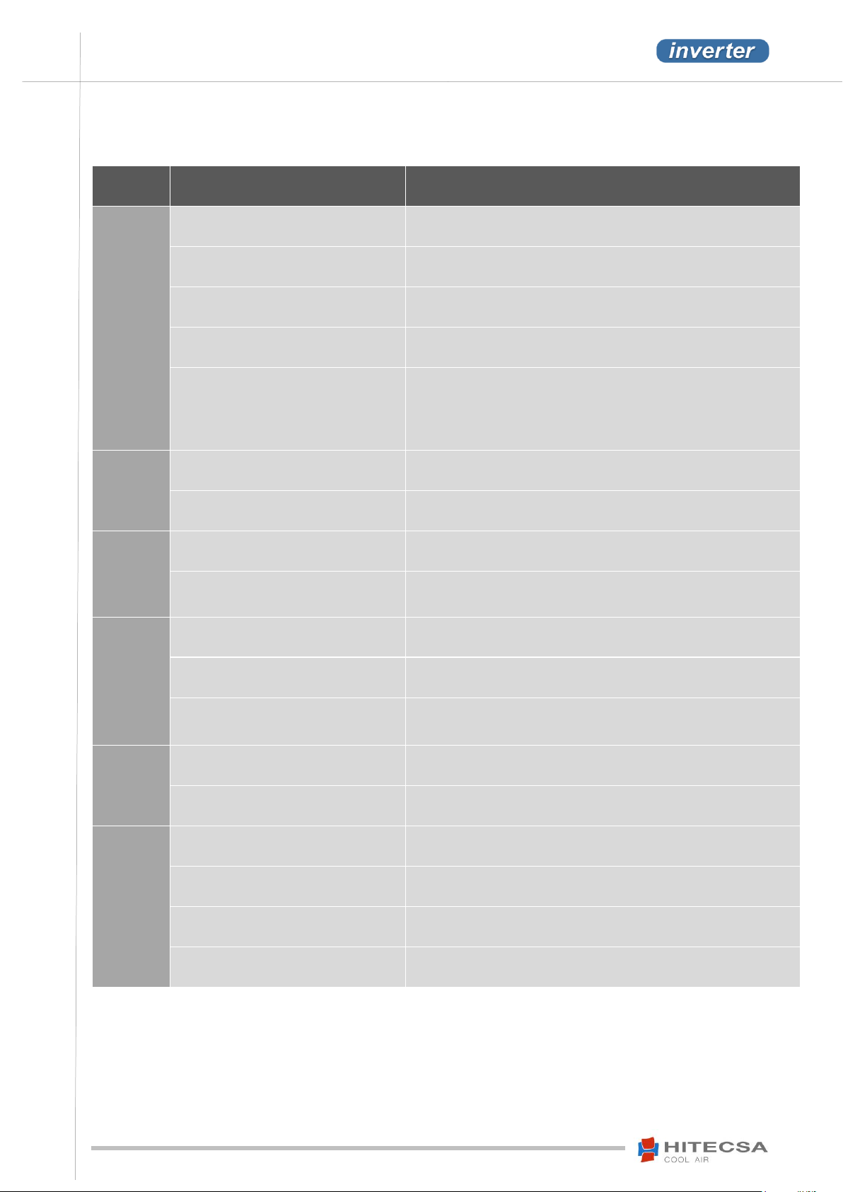
Diagnosis / Failure
OPERATION
VENTILADORES EC
28
Page 29
ACVIBA HE
AIR-AIR PACKAGED UNITS
COMPACT VERTICAL INVERTER
IOM_ACVIBA HE_35ia80i_207910_190501_EN
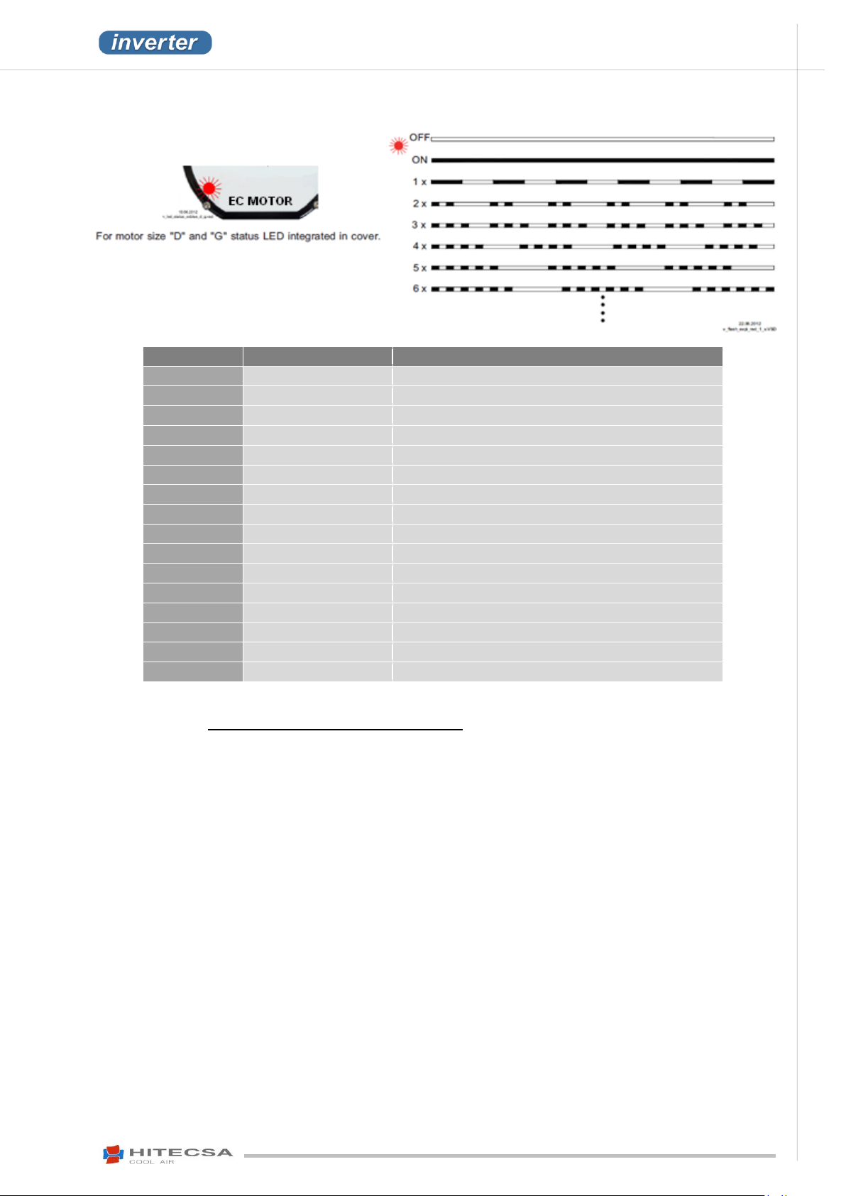
LED Code
Alarm relay *
Cause (Explanation)
OFF
Open
No line voltage
ON
Closed
Normal operation without fault
1x
Closed
Not enable = OFF
2x
Closed
Active temperature management
3x
Open
HALL-IC fault
4x
Open
Line failure (only for 3~ types)
5x
Open
Motor blocked
6x
Open
IGBT fault
7x
Open
DC under voltage
8x
Open
DC overvoltage
9x
Closed
IGBT cooling down period
11x
Open
Fault motor start
12x
Open
Line voltage too low
13x
Open
Line voltage too high
14x
Open
Error peak current
17x
Open
Temperature alarm
Status Out with flash code
* Alarm relay: function programmed by manufacturer: error message not reversed.
The alarm “Serious alarm thermostats interblock security” appears in pGD or Mini pGD.
29
Page 30
IOM_ACVIBA HE_35ia80i_207910_190501_EN
ACVIBA HE
AIR-AIR PACKAGED UNITS
COMPACT VERTICAL INVERTER
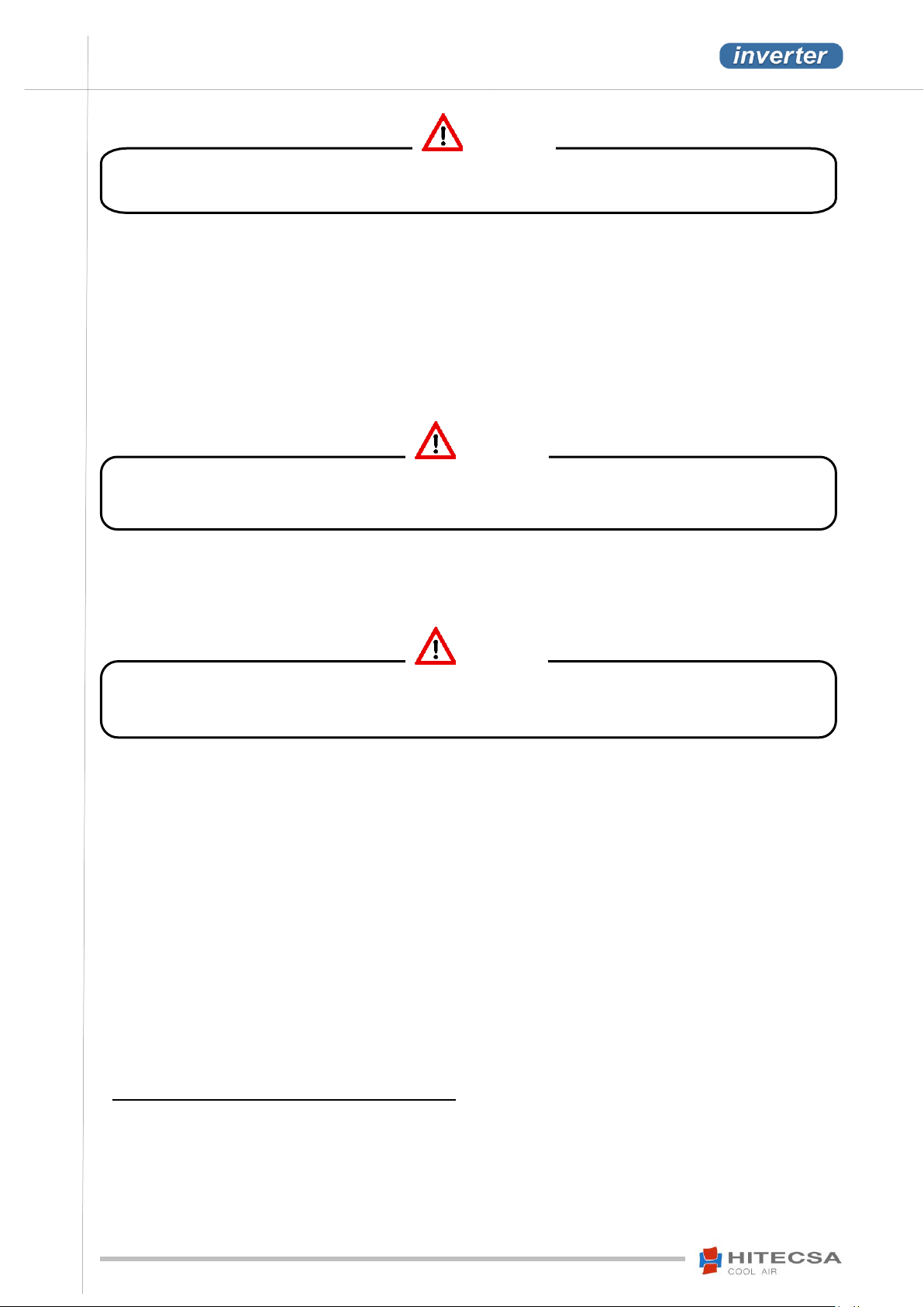
Before completing any service or maintenance operation, turn the main power switch off to avoid any
personal injuries. Lock it so that anybody else than a qualified technician can switch it on.
Never use oxygen to pressurize the system or purge lines for leak test. Oxygen reacts violently with oil
which may entail an explosion that could lead to damages, personal injury or event death.
Should it be necessary to complete brazing operation first of all proceed to filling the circuit with dry
nitrogen. Burning refrigerant produces toxic gas emissions.
WARNING!
WARNING!
WARNING!
MAINTENANCE
It is advisable to schedule maintenance visits every 1,000 operating hours, as well as at the end of summer. Please
keep an updated record of all maintenance operations and readings (maintenance sheet).
Repairing operations must be carried out by trained specialists only.
Wear safety shoes and gloves adapted to each operation!
Please observe the safety regulations and the worker’s protection rules for any maintenance and service operation
(EN 50 110, IEC 364).
In the event of leak any manipulation and/or recovery of refrigerant shall be completed by qualified and authorized
personnel in accordance with the valid regulation. Add the quantity of oil that has been lost.
REFRIGERANT CHARGE
Should it be necessary to add or recover refrigerant use a digital scale that is suitably reinforced and prepared to
withstand the handling of the refrigerant bottle.
Charge to be in the LIQUID state.
Introduction of R-410A refrigerant in the liquid state inside empty tubes produces temperatures below 0ºC until the
internal pressure reaches 7 bars.
Leaks should be repaired immediately.
Never overcharge the system.
Never use the compressor as a vacuum pump.
If leakage symptoms appear during operation proceed to a leak test.
A HCF detector is necessary in case of small leaks.
If a gas leak is detected proceed to removing and recuperating the entire refrigerant charge. Pressurize the system
with dry nitrogen. If no leak is detected proceed to vacuuming the system and refill with refrigerant.
Do not reintroduce the used refrigerant, send it to an authorized recycling plant.
COMPRESSOR LUBRICATION
R-410A refrigerant compressors use synthetic oils. Each manufacturer uses a specific oil for his product.
The compressor or system should not remain open to atmosphere for more than 15 minutes.
The used synthetic oils are of type POE (Polyol Ester) and PVE (Polyvinyl-ether). They have a high solubility level with
the R-410A. These types of oil are very hygroscopic and shall be handled with more care than the conventional oil.
Moreover, when these synthetic oils are mixed with minerals (MO) or alkylbenzenes (AB), they deteriorate causing
capillary blockage or failure in the compressor.
DO NOT MIX THEM UNDER ANY CIRCUMSTANCES.
30
Page 31

ACVIBA HE
AIR-AIR PACKAGED UNITS
COMPACT VERTICAL INVERTER
IOM_ACVIBA HE_35ia80i_207910_190501_EN
MAINTENANCE
CONSERVATION AND CLEANING
Precaution!
Do not use aggressive cleaning products nor varnish solvents.
Avoid water penetration inside the motor or the electronic components (e.g. through the direct contact with joints or
holes of the motor), observe the protection class (IP).
Electrical circuit: Make sure that all the electrical connections –wires, contactors and terminals- are properly tight.
Register the readings of kW and amperes at each compressor and fan motor phase. Check the start current. Check that
all the mechanical components, pressure switches and so on are working properly.
Refrigeration circuit: Check if there is any refrigerant leak, noises or vibration. Proceed to measuring temperatures
and/or pressures of the most important components of the system and register them on the maintenance sheet
(compressor discharge and suction, expansion valve, exchangers’inlet and outlet, etc…).
Compressor: Check regularly the lubricant level, the presence of vibrations or noise and the motor insulation.
Drainage system: Verify the condition and the correct operation of the drainage tray and drain trap. It is necessary to
clean the condensate trays after the first day of operation. Then, clean them at least once a year. Take into account the
meteorological conditions, e.g. in areas where falling leaves or the flight of seeds may obstruct the drain trap. Clean
them also at mid and late spring and autumn. The dates are approximate and will depend on the plants blooming, falling
leaves and seeds seasons. Other factors such as human activities may interfere in the cleanliness conditions.
Air filters: Clean the filters after the first operating hours to remove possible light materials such as pieces of paper or
polystyrene, etc. that may have been dragged through air circulation. Clean again every 3 months (or more often
depending on operation). The filters can be cleaned with soapy water. Then rinse them with clean water and let dry. If
necessary replace the filters before they are in poor conditions (refer to the current legislation, EN 779, UNE-EN
13053…).
Coils: At least once a year clean the coils with water and detergent, then dry with air at low pressure. Never clean with a
wire brush, water and/or air at high pressure (max. 6 bar).
Fans: Check the direction of rotation of the fans, verify the supporting parts. Check the transmission elements and the
operating status.
Before handling the fan make sure that it is disconnected from the main power supply even though it is already stopped
and control that nobody may start it during the intervention.
- A regular inspection of the unit is required to avoid dirt accumulation in propellers, turbines, motors and grids that
could entail risks and significantly shorten their life. The frequency will depend on the working conditions.
- Keep the airways of the fan free – danger because of objects dropping out!
- Check the free flow of the condensation water through the evacuation openings is necessary (if there are any).
- During cleaning operations be very careful not to unbalance the propeller or the turbine.
- In case of incorrect cleaning operations no guarantee is assumed regarding corrosion formation / paint adhesion for
unpainted / painted fans.
- To avoid humidity accumulation in the motor the fan must be operated during at least 1 hour at 80 to 100% of its
maximum speed before cleaning!
- After cleaning, the fan must be operated during 2 hours at 80 to 100% of the maximum speed to dry it!
- Check the fan regularly to detect possible mechanical vibrations (recommended every 6 months). Keep in mind the
limit values indicated the ISO 14694 and perform correction measures in case of exceeding them (e.g. posterior
balance to be completed by trained specialists).
- Check the impeller, in particular weld-seams, for possible cracks.
- The fan or motor is maintenance-free due to the use of ball bearings with “life-long lubrication”. At the end of the
grease life (30-40.000h approx.) it is necessary to replace the bearing. Please contact our Service Department in this
case as for all other damage (e.g. to the coil or electronics).
31
Page 32
IOM_ACVIBA HE_35ia80i_207910_190501_EN
ACVIBA HE
AIR-AIR PACKAGED UNITS
COMPACT VERTICAL INVERTER
MAINTENANCE
REPAIRS
Please observe the safety regulations and the protection rules of the worker for all maintenance and service
operations.
Brazing operations are forbidden to repair the mechanical parts such as the fans, compressors, valves, etc…
Por motivos de seguridad no está permitido realizar por cuenta propia intervenciones ni modificaciones en el
aparato. Todas las modificaciones planificadas deben ser aprobadas por escrito por el fabricante.
Use only spare parts/ wear parts / original accessories from the manufacturer of the fans. These parts have been designed
especially for the unit. If you use parts from other manufacturers it is not guaranteed that they have been manufactured
to resist loads that they will have to support or that they meet the relevant safety requirements.
The parts and any special equipment that have not been supplied by the manufacturer of the fans are not authorized by
these manufacturers and cannot be used for the equipment.
32
Page 33
ACVIBA HE
AIR-AIR PACKAGED UNITS
COMPACT VERTICAL INVERTER
IOM_ACVIBA HE_35ia80i_207910_190501_EN
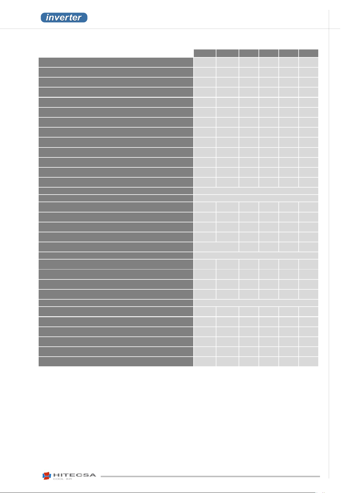
35i
40i
45i
55i
70i
80i
Inverter compressors
● ● ● ● ●
●
Acoustic insulation around compressor
● ● ● ● ●
●
Kit for outdoor installation
○ ○ ○ ○ ○
○
Phase sequencer
● ● ● ● ●
●
Indoor and outdoor Plug-fan with EC motor
● ● ● ● ●
●
Upgraded outdoor fan
○ ○ ○ ○ ○
○
Upgraded indoor fan
○ ○ ○ ○ ○
○
Electronic expansion valve
● ● ● ● ●
●
Circuit-breakers and thermal relays for motors
● ● ● ● ●
●
Suction accumulator
○ ○ ○ ○ ○
○
Liquid container
● ● ● ● ●
●
Anti-corrosion pre-treated coil Condenser
○ ○ ○ ○ ○
○
Anti-corrosion pre-treated coil evaporator
○ ○ ○ ○ ○
○
Free Cooling mixing module 2 dampers
Contact Hitecsa
Thermoenthalpic Free Cooling mixing module 2 dampers
Contact Hitecsa
Th-Tune
● ● ● ● ●
●
Mini PGD
○ ○ ○ ○ ○
○
PGD controller
○ ○ ○ ○ ○
○
2 stage filter
○ ○ ○ ○ ○
○
Electrical heater for defrost
Contact Hitecsa
× × ×
×
Air Quality probe (CO2)
Contact Hitecsa
Smoke detector
○ ○ ○ ○ ○
○
Dirty filter sensor
○ ○ ○ ○ ○
○
Remote room probe
○ ○ ○ ○ ○
○
Modbus
● ● ● ● ●
●
Lonworks
Contact Hitecsa
Bacnet IP
○ ○ ○ ○ ○
○
TCP IP
○ ○ ○ ○ ○
○
Rubber-metal shockabsorbers
○ ○ ○ ○ ○
○
Protection grille for outdoor coils
○ ○ ○ ○ ○
○
Oil separator
× × × × ×
×
Cooling only
× × × × ×
×
●
Standard
○
Option
×
Not available
OPTIONS
*Should you need any other configuration or function please contact our sales department.
33
Page 34
IOM_ACVIBA HE_35ia80i_207910_190501_EN
ACVIBA HE
AIR-AIR PACKAGED UNITS
COMPACT VERTICAL INVERTER
REFRIGERANT DATA
SAFETY DATA: R410A
Toxicity
Low
Contact with Skin
R410 A vapours can irritate the skin and eyes. In liquid form, it can freeze skin on contact. If contact with skin occurs,
flush the exposed area with lukewarm water until all of the chemical is removed. If there is evidence of frostbite, bathe
in lukewarm water.
Contact with Eyes
If contact with eyes occurs, immediately flush with large amounts of lukewarm water for at least 15 minutes, lifting
eyelids occasionally to facilitate irrigation. Seek medical attention as soon as possible.
Ingestion
Very unlikely - should something happen, it will cause frost burns. Do not induce vomiting. Only if the patient is
conscious, wash out mouth with water and give some 250 ml of water to drink. Then, obtain medical attention.
Inhalation
Inhalation of the R410A vapour may cause irritation. Vapour inhalation at high concentrations may result in asphyxiation
or the heart may become sensitized, causing cardiac arrhythmia. When concentration of R410A reach levels which
reduce oxygen to 14-16% by displacement, symptoms of asphyxiation will occur. An individual exposed to high
concentrations of R410A must be given medical attention immediately. Adequate ventilation must be provided at all
times.
Recommendations
Semiotics or support therapy is recommended. Cardiac sensitisation has been observed that, in the presence of
circulating catecholamines such as adrenalin, may cause cardiac arrhythmia and accordingly, in case of exposure to
high concentrations, cardiac arrest.
Prolonged Exposure
R410A: a study on the effects of exposure to 50,000 ppm during the whole life of rats has identified the development
of benign testicle tumour.
This situation should therefore be negligible for personnel exposed to concentrations equal to or lower than professional
levels.
Professional Levels
R410A: Recommended threshold: 1000 ppm v/v - 8 hours TWA.
Stability
R410A: without specifying
Conditions to Avoid
Do not use in the presence of high temperatures, flames, burning surfaces and excess humidity.
Hazardous Reactions
Contact with certain red-hot metals may result in exothermic or explosive reactions and yield toxic and/or corrosive
decomposition products. Specific materials to avoid include freshly abraded aluminium surfaces and active metals such
as sodium, potassium, calcium, powdered aluminium, magnesium and zinc.
Hazardous Decomposition
Products
R410A: Halogen acids produced by thermal decomposition and hydrolysis.
General Precautions
Do not inhale concentrated vapours. Their concentration in the atmosphere should not exceed the minimum preset
values and should be maintained below the professional threshold. Being weightier than the air, the vapour
concentrates on the bottom, in narrow areas. Therefore, the exhaust system must work at low level.
Respiratory System
Protection
If you are in doubt about the concentration in the atmosphere, it is recommended to wear a respirator approved by an
accident prevention Authority, of the independent or oxygen type.
Storage
Cylinders must be stored in a cool, dry and properly ventilated storage area away from heat, flames, corrosive
chemicals, flumes, explosives and be otherwise protected from damage. Keep a temperature below 50°C.
Protective Clothing
Wear overalls, protective gloves and goggles or a mask.
Accidental Release
Measures
It is important to wear protective clothing and a respirator. Stop the source of the leak, if you can do this without danger.
Negligible leaks can be left evaporating under the sun, providing that the room is well ventilated. Considerable leaks:
ventilate the room. Reduce the leak with sand, earth or other absorbing substances. Make sure that the liquid does is
not channelled into gutters, sewers or pits where the vapours are likely to create a stuffy atmosphere.
Disposal
The best method is recovery and recycling. If this method is not practicable, dispose according to an approved
procedure, which shall ensure the absorption and neutralization of acids and toxic agents.
Fire Fighting Information
R410A: Not flammable in the atmosphere.
Cylinders
The cylinders, if exposed to fire, shall be cooled by water jets; otherwise, if heated, they may explode.
Protective Fire Fighting
Equipment
In case of fire, wear an independent respirator and protective clothing.
APPENDIX: SAFETY DATA R410A
34
Page 35
ACVIBA HE
AIR-AIR PACKAGED UNITS
COMPACT VERTICAL INVERTER
IOM_ACVIBA HE_35ia80i_207910_190501_EN
Subject to modifications without prior notice.
35
 Loading...