

Hitecsa ACVA STD 351, ACVBA STD 351, ACVA STD 501, ACVA STD 711, ACVBA STD 401 Installation, Operation And Maintenance Instructions
...Page 1
ACVA - ACVBA
Installation, operation and maintenance instructions
1
Installation, operation and maintenance instructions
ACVA – Cooling Only
ACVBA – Heat Pump
SELF-CONTAINED VERTICAL UNITS
MONOBLOC AIR-AIR
Page 2

ACVA - ACVBA
Installation, operation and maintenance instructions
2
INDEX
INTRODUCTION ................................................................................
3
SAFETY PRECAUTIONS
................................................................................
4
RECEPTION
................................................................................
5
INSTALLATION LOCATION
................................................................................
6
START UP
................................................................................
8
TECHNICAL DATA
................................................................................
11
DIMENSIONS
................................................................................
14
REFRIGERANT CHARGE
................................................................................
18
MAINTENANCE
................................................................................
19
Page 3
ACVA - ACVBA
Installation, operation and maintenance instructions
3
INTRODUCTION
The contents of this manual are designed to assure the correct installation, adjustment and
maintenance of the unit, therefore:
• Read the instructions with due care and attention.
• The appliance must be installed, tested and serviced by properly qualified staff
licensed in accordance with the established legislation.
• The manufacturer declines all liability and warranty coverage is automatically waived,
if electrical and/or mechanical modifications to the unit. Tampering and unauthorized
repairs or modifications to the unit will automatically void the warranty.
• Observe the safety regulations in force at the time of installation.
• Make sure that the characteristics of the mains network conform to the data on the
serial number plate placed on the unit.
• Keep this manual and the wiring diagram with care and make sure that they are
available for consultation by the operator whenever necessary.
• Packing materials (plastic wrappings, expanded polystyrene, etc) are potentially
hazardous and must be kept out of reach of children. Recycle packing materials in
accordance with local legislation.
• The units must be used only for the purpose for which they are designed .The
manufacturer bears no responsibility in the case of applications other than the
specified use.
• Disconnect the unit in the event of breakdowns or malfunctions.
• If repairs are necessary, use only HITECSA approved service centres and always insist
on original spare parts. The use of non-original parts and/or unauthorized service
centres may result in unsafe operation of the unit.
REGULATIONS AND CERTIFICATIONS
ISO 9001:2008 certification: HITECSA AIRE ACONDICIONADO S.L.U., trying always to find the
customer satisfaction, has obtained the ISO 9001:2008 Quality System referred to its
production activity. This will results in a continuous determination to improve quality and
reliability of all our products; commercial activities, design, raw materials, production and
after-sales service, are the means to reach our goal.
CE marking: our machines have got the CE mark, in conformity with the essential requirements
of the applicable EC directives and their last modifications as well as with the national
legislation of each country.
Page 4

ACVA - ACVBA
Installation, operation and maintenance instructions
4
SAFETY PRECAUTIONS
• Installation and maintenance of air conditioning equipment can be dangerous because the
system is under pressure, because some of its elements have high temperatures and
include electrical components.
• Only qualified and trained service staff should install,commission and carry out
maintenance works. Unqualified staff should only carry out basic tasks such as cleaning
and replacement of filters, etc.
• In every visit, all precautions should be taken into account: those recommended in the
Installation, operation and maintenance instructions, as well as the ones indicated in labels
of the unit. Do not forget to strictly follow any other safety codes.
• Use safety glasses, work gloves and any other safety accessory necessary.
• For brazing operations use a quenching cloth and have at close distance a fire extinguisher.
WARNING!
Before starting installation, service or maintenance, turn off the main power switch in order
to avoid electrical shock that may cause personal damages.
• When repairing the unit, use only original spare parts and install them properly in the
same position where old parts were placed.
These units are designed to work with 100% recirculated air. The installation with 100% outdoor air
is prohibited. See application limits.
•
Do not install the unit in explosive atmosphere.
•
Page 5
ACVA - ACVBA
Installation, operation and maintenance instructions
5
RECEPTION
INSPECTION UPON RECEIPT
• Units are delivered with special protective packing; therefore when it arrives, please
inspect it carefully to check that no damage has occurred during transport and that the
unit has been supplied complete with all parts specified in the order. If any damage is
found, immediately file a claim with the transport company.
• Verify the correct voltage of the nameplate and make sure it’s in accordance with local
power supply.
• In case of any flaw or anomaly detected, please contact HITECSA
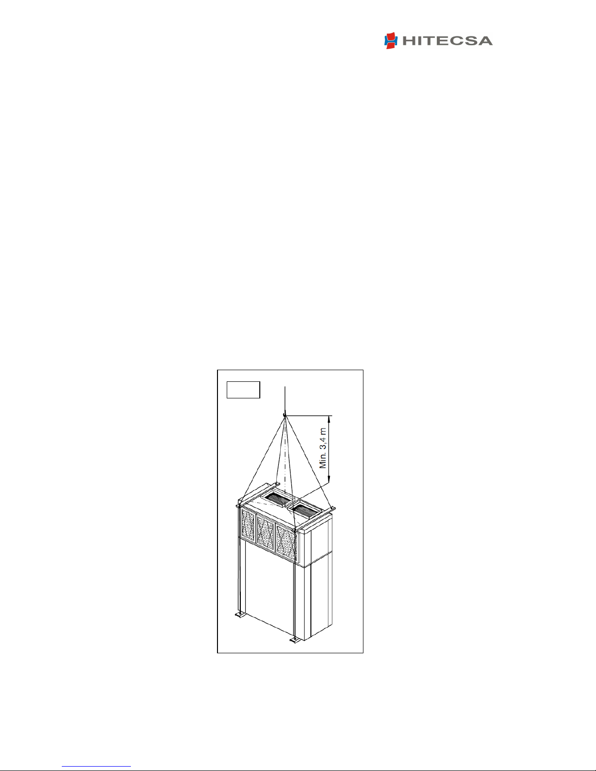
RIGGING
• Before moving the unit, make sure that all panels are well fixed.
• Raise and set down the equipment carefully.
• Do not tilt the unit more than 15 degrees during transportation.
• When lifting the unit, make sure that it’s balanced and stable; bear in mind that the
heaviest part is where the compressor is installed.
• Check minimum length of wire raising (Fig.1)
Fig
.1
Page 6
ACVA - ACVBA
Installation, operation and maintenance instructions
6
STORAGE
If the equipment is going to be stored please follow the instructions below in order to avoid
damages, corrosion or deterioration:
• Keep the unit away from direct sunlight, rain, sand, wind or temperatures above 50ºC
• Storage temperature: maximum 50ºC, minimum -10ºC
• Maximum humidity: 90%
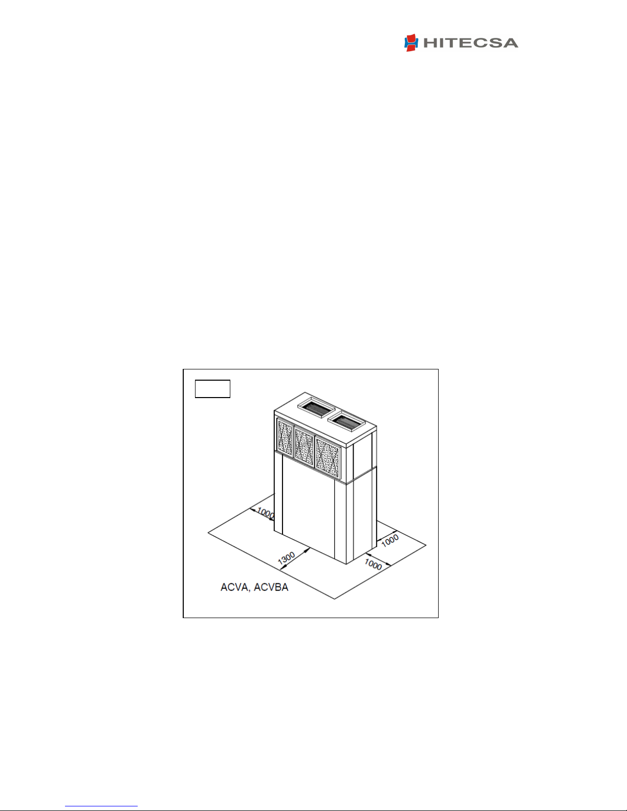
INSTALLATION LOCATION
• Check if the base is able to support the weight of unit during operation.
• Reserve a minimum service area according to Fig. 2.
• Choose a place free of dust or any other foreign material that could clog or damage the
condenser coil. The location should also be a place that cannot be flooded.
• Consult and respect all regulations concerning installation of air conditioning systems.
• Check if sound waves do not disturb anyone.
SERVICE AREA (mm)
Fig
.2
Page 7

ACVA - ACVBA
Installation, operation and maintenance instructions
7
UNIT SETTLEMENT
• Make sure that the unit is correctly levelled.
• The bed frame should be strong and solid enough to support the weight of the machine.
• Verify that the indoor drain is working properly.
WEIGHT DISTRIBUTION (Kg)
Page 8

ACVA - ACVBA
Installation, operation and maintenance instructions
8
BEFORE START UP
• Check the following points:
o Wires are well tightened.
o Panels are firmly secured with screws.
o There are no oil or refrigerant leaks.
o The unit is correctly levelled.
o There is enough space for service and maintenance.
o Drainage is not blocked.
o Crankcase heater has been working at least 24 hours prior to the start-up.
o Air filters are clean and correctly mounted.
o Grilles, air diffusers, air ducts and flexible connections are in good condition.
o Electrical power source is in accordance with what is said in the nameplate.
o Fans rotate in the right direction.
.
START UP
• Start up should be performed by qualified technical people.
• Use a start up check list: record inlet and outlet temperatures and pressures, outdoor air
temperature, volts and amps of each compressor and each fan motor, suction and
discharge pressure of each compressor.
• Use a similar check list for service and maintenance works.
• Remember that after 4 hours of operation, it is necessary to clean the filters.
• Monitor at least 3 cooling cycle operations.
OPERATION LIMITS
COOLING MODE
TEMPERATURE MINIMUM MAXIMUM
Outdoor ambient 19ºC 46ºC
Indoor dry bulb 19ºC 32ºC
Indoor wet bulb 15ºC 23ºC
HEATING MODE
TEMPERATURE MINIMUM MAXIMUM
Indoor dry bulb 18ºC 26ºC
Outdoor wet bulb -7ºC 18ºC
*For temperatures of less than 19ºC it is necessary
to use the condensation control optional.
*
Page 9

ACVA - ACVBA
Installation, operation and maintenance instructions
9
ELECTRIC CONNECTIONS
Legend
1. Main power 400/3/50 + neutral
2. Earth
3. Crankcase heater (230/1/50)
4. Time-delay fuses or circuit breaker (MCB) curve D
5. Main power switch
6. Remote control
WARNING!
Before starting installation, service or maintenance, turn off the main power switch in order
to avoid electrical shock that may cause personal damages.
• Main power supply of the unit should agree with the data shown on the nameplate.
HITECSA will not be held responsible for damages resulted from non observance of the
above.
• Always use the wiring diagram sent with the unit to make electrical connections.
• Check that the crankcase heater has been working at least 24 hours prior to the start up of
the unit.
• Current supply should be within 10% of Volts and Amperes indicated on the unit
nameplate.
• Do not operate the unit at different current from that shown on the unit nameplate.
• The installer should put line protection elements in compliance with current legislation.
• The interconnecting wires should be protected with a tube or put inside a groove channel.
2
1
4
5
3
6
Page 10

ACVA - ACVBA
Installation, operation and maintenance instructions
10
DRAINAGE
• Indoor drainage (of condensate water) has a 3/4” MPT connection.
• Condensate drain line diameter should be equal or larger than the unit connection
depending on line length and general building configuration.
• Drainage line should have a minimum inclination of 2% for proper water evacuation.
• When drainage line is exposed to temperatures below 0ºC, it is necessary to provide
thermal insulation or electrical heating wire to avoid water freezing and tube damages
•
It is advisable to install a trap with proper dimensions.
Page 11

ACVA - ACVBA
Installation, operation and maintenance instructions
11
TECHNICAL AND ELECTRIC DATA
CAPACITIES
Cooling capacity
kW
9,8
12,5
14,4
18,9
19,6
Heating capacity
kW
10,4
13,7
15,0
20,0
21,0
EER efficiency
2,2
2,2
2,0
2,3
2,1
COP efficiency
2,5
2,7
2,3
2,6
2,6
Number of refrigerant circuits
11111
REFRIGERANT
Charge
Kg
3,50 4,20 4 6,20 5,80
COMPRESSOR
Type
Rotary
Scroll
Scroll
Scroll
Scroll
Quantity
11111
Type of oil
PVE
PVE
PVE
PVE
PVE
Volume of oil
l
1,3
1,7
1,7
1,7
2,8
Type
FV60S
FV68S
FV68S
FV68S
FV68S
OUTDOOR FAN
Type
Nominal airflow
m3/h
4300
3950
4900
6800
6800
Available static pressure
Pa5050505050Model
10/10 SS
12/12 SS
12/12 SS
15/15 SS
15/15 SS
Capacity
kW
0,75
0,55
0,75
1,1
1,1
Speed
r.p.m.
1083
825
829
746
746
INDOOR FAN
Type
Nominal airflow
m3/h
2315
2600
3540
4720
4720
Available static pressure
Pa4350605555Model
10/10 DD
10/10 SS
10/10 SS
12/12 SS
12/12 SS
Capacity
kW
0,25
0,55
0,55
0,75
0,75
Speed
r.p.m.
872
870
1032
809
809
Voltage
Total input power cooling
kW
4,6
5,7
7,3
8,4
9,27
Total input current cooling
A
9,2
10,5
13,3
16,0
17,8
Total input power heating
kW
4,2
5,1
6,5
7,9
8,16
Total input current heating
A
8,4
9,7
11,8
14,7
15,8
Max. Input power cooling
kW
5,4
7,3
9,5
11,0
11,10
Max. Input current cooling
A
9,7
12,3
15,0
19,3
19,5
Max. Input power heating
kW
5,0
6,3
7,5
9,0
9,21
Max. Input current heating
A
8,9 10,9 12,6 15,6 16,5
Starting current
A
48,0
63,0
66,0
67,0
102,0
DIMENSIONS AND WEIGHT
Lenght
mm
937
937
1087
1130
1130
Width
mm
750
750
750
800
800
Height
mm
1603
1603
1603
1900
1900
Weight
Kg
251
276
290
367
392
400V-~3N-50Hz
GENERAL SPECIFICATIONS FOR ELECTRIC INSTALLATION
Centrífugal, double suction
R-410A
1725
Type
Global warming potential (GWP)
Centrífugal, double suction
701 721
ACVA STD
351 501
ACVBA STD
401
Page 12

ACVA - ACVBA
Installation, operation and maintenance instructions
12
CAPACITIES
Cooling capacity
kW
22,7
24,2
30,1
34,9
37,8
Heating capacity
kW
23,9
25,3
31,7
38,2
39,5
EER efficiency
2,1
2,2
2,3
2,4
2,3
COP efficiency
2,3
2,6
2,6
2,9
2,6
Number of refrigerant circuits
11112
REFRIGERANT
Charge
Kg
7,20
7,70
9,50
10,50
2 x 6,5
COMPRESSOR
Type
Quantity
11112
Type of oil
PVE
PVE
PVE
POE
PVE
Volume of oil
l
2,8
2,8
2,8
3,3
2 x 1,7
Type
FV68S
FV68S
FV68S
160SZ
FV68S
OUTDOOR FAN
Type
Nominal airflow
m3/h
7400
7714
10000
12500
13600
Available static pressure
Pa5057505088Model
15/15 SS
15/15 SS
15/11 G2L
15/11 G2L
2 x 15/15 SS
Capacity
kW
1,5
1,5
1,5
2,2
2 x 1,1
Speed
r.p.m.
834
808
686
760
718
INDOOR FAN
Type
Nominal airflow
m3/h
5133
5125
6277
8000
8000
Available static pressure
Pa53837391
130
Model
12/12 SS
12/12 SS
12/12 G2L
12/12 G2L
12/12 G2L
Capacity
kW
1,1
1,1
1,1
1,5
1,5
Speed
r.p.m.
891
910
800
896
862
Voltage
Total input power cooling
kW
10,9
10,9
13,4
14,4
16,6
Total input current cooling
A
20,2
20,4
24,5
27,8
31,0
Total input power heating
kW
10,3
9,6
12,4
13,2
15,9
Total input current heating
A
19,3
18,3
22,3
25,6
28,4
Max. Input power cooling
kW
13,8
13,6
16,5
17,8
14,2
Max. Input current cooling
A
23,5
23,2
28,0
30,9
37,4
Max. Input power heating
kW
12,3
12,0
15,8
16,4
18,3
Max. Input current heating
A
21,2
20,5
26,0
28,5
30,1
Starting current
A
102,0
102,0
102,0
158,0
67,0
DIMENSIONS AND WEIGHT
Lenght
mm
1130
1130
1700
1700
2000
Width
mm
800
800
870
870
939
Height
mm
1900
1900
1900
1900
1997
Weight
Kg
423
440
553
558
730
Scroll
400V-~3N-50Hz
GENERAL SPECIFICATIONS FOR ELECTRIC INSTALLATION
1201 1402
ACVBA STD
Type R-410A
ACVA STD
751 801 1001
Centrífugal, double suction
Global warming potential (GWP) 1725
Centrífugal, double suction
Page 13

ACVA - ACVBA
Installation, operation and maintenance instructions
13
CAPACITIES
Cooling capacity
kW
49,6
50,2
63,1
73,6
78,5
Heating capacity
kW
51,2
51,9
65,5
81,9
81,9
EER efficiency
2,6
2,5
2,4
2,6
2,3
COP efficiency
3,0
2,9
2,9
3,0
2,8
Number of refrigerant circuits
22222
REFRIGERANT
Charge
Kg
2 x 6,3
2 x 6,6
2 x 8,0
2 x 10,3
2 x 9,0
COMPRESSOR
Type
Quantity
22222
Type of oil
PVE
PVE
PVE
POE
POE
Volume of oil
l
2 x 2,8
2 x 2,8
2 x 2,8
2 x 2,3
2 x 3,3
Type
FV68S
FV68S
FV68S
160SZ
160SZ
OUTDOOR FAN
Type
Nominal airflow
m3/h
15600
16000
22000
23000
23000
Available static pressure
Pa
110
110
123
142
142
Model
2 x 15/15 SS
2 x 15/15 SS
2 x 18/18 SS
2 x 18/18 SS
2 x 18/18 SS
Capacity
kW
2 x 1,5
2 x 1,5
2 x 2,2
2 x 3
2 x 3
Speed
r.p.m.
808
808
671
734
787
INDOOR FAN
Type
Nominal airflow
m3/h
10000
10000
11000
12000
12000
Available static pressure
Pa
145
145
175
160
160
Model
12/12 G2L
12/12 G2L
15/11 G2L
15/11 G2L
15/11 G2L
Capacity
kW
2,2
2,233
3
Speed
r.p.m.
913
913
734
787
734
Voltage
Total input power cooling
kW
19,8
20,8
27,0
28,3
34,2
Total input current cooling
A
36,0
37,0
48,1
56,1
57,2
Total input power heating
kW
17,5
18,6
23,7
27,0
28,9
Total input current heating
A
34,8
35,8
44,1
52,7
52,7
Max. Input power cooling
kW
25,4
26,6
33,2
33,5
42,7
Max. Input current cooling
A
41,9
43,0
55,0
58,8
63,9
Max. Input power heating
kW
21,3
22,6
30,2
30,6
36,2
Max. Input current heating
A
38,2
39,3
51,4
55,0
58,7
Starting current
A
102,0
102,0
158,0
179,0
158,0
DIMENSIONS AND WEIGHT
Lenght
mm
2000
2000
2600
2600
2600
Width
mm
939
939
980
980
980
Height
mm
1997
1997
2174
2174
2174
Weight
Kg
810
820
1080
1115
1135
400V-~3N-50Hz
Scroll
GENERAL SPECIFICATIONS FOR ELECTRIC INSTALLATION
Centrifugal, double suction
R-410A
Global warming potential (GWP)
Centrifugal, double suction
ACVA STD
1502 1602 2002 2302 2402
ACVBA STD
Type
(1) COOLING: Outdoor temperature: 35 °C. Indoor WB temperature 19 °C.
DIMENSIONS
(1) COOLING: Outdoor temperature: 35
°
C. Indoor WB temperature 19
°
C.
(2) HEAT PUMP: WB outdoor temperature.: 6 °C. Indoor temperature: 20 °C.
Page 14

ACVA - ACVBA
Installation, operation and maintenance instructions
14
DIMENSIONS
ACVA
–
ACVBA
351 -
501
Page 15

ACVA - ACVBA
Installation, operation and maintenance instructions
15
ACVA
–
ACVBA
701 - 801
Page 16

ACVA - ACVBA
Installation, operation and maintenance instructions
16
ACVA
–
ACVBA
1001
- 1201
Page 17

ACVA - ACVBA
Installation, operation and maintenance instructions
17
ACVA
–
ACVBA
1
402 – 1502
-
1602
Page 18

ACVA - ACVBA
Installation, operation and maintenance instructions
18
ACVA
–
ACVBA
2002
– 2302 - 2402
Page 19

ACVA - ACVBA
Installation, operation and maintenance instructions
19
REFRIGERANT CHARGE
WARNING!!!
Never use oxygen to carry out leak tests. Oxygen reacts violently when in contact with oil
and could cause an explosion resulting in damage, personal injuries or even death.
• Should it be necessary to add or recover refrigerant, do it always in LIQUID phase, never in
gas or vapour phase since this would cause wrong mixing conditions.
• Due to its high pressure and quick evaporation, refrigerant R410A cannot be kept in liquid
phase inside charge cylinder because bubbles would form, making reading difficult.
WARNING!!!
If it’s necessary to make welding operations, you must fill the circuit with dry nitrogen.
Combustion of R410a refrigerant generates toxic gases.
• Repair immediately any refrigerant leak.
• Never overcharge the system.
• Never use compressor as a vacuum pump.
• If symptoms of refrigerant loss appear during operation, it’s necessary to carry out a leak
test. Leak detectors usually employed with CFC and HCFC cannot be used with R410a, due
to chlorine in its composition. A leak detector for R134a may be used but the sensibility
will be lower (when sensibility is 1 for R134a, it falls to 0,6 for R410a).
• To find small leaks, you will need a detector for HCF. Sensibility for R410A is approx. 23
grams per year.
• If a gas leak is found, it will be necessary to remove and completely recover the refrigerant
charge. Pressurize the system with dry nitrogen. If no leakage is detected, then do the
vacuum and charge again with refrigerant.
Page 20

ACVA - ACVBA
Installation, operation and maintenance instructions
20
MAINTENANCE
WARNING!!!
Before performing any service or maintenance operation, turn off the main power switch of
the system to avoid any personal injuries. Block the power switch so that nobody other than
a qualified technician can switch on electrical power.
• It is advisable to do maintenance works every 1.000 operating hours as well as at the
beginning of each cooling season.
• Coils: at least once a year, clean condenser coils with water and detergent, then dry
with air at a pressure of 600 kPa. Never clean with wire brush.
• Fans and motors: adjust transmission belt at least twice during the first month of
operation and then check every 1.000 hours. Fan and motors do not need additional
lubrication.
• Drainage system: verify condition and good operation of the drainage tray. Make sure
that holes at the base of the unit are not blocked so that evacuation can be properly
done.
• Refrigeration circuit: check for oil refrigerant leaks, noises or system’s vibrations. Take
measurements of temperatures and pressures of components and record them on the
maintenance form.
•
Electrical circuit: make sure that all electrical connections -wires, contactors,
terminals- are properly tight. Record the measurements (volts and amperes) of each
compressor and fan motor. Verify the starting current. Check the good operation of all
relays, pressostats and phase sequence relay of Scroll compressor.
Page 21

ACVA - ACVBA
Installation, operation and maintenance instructions
21
www.hitecsa.com
HITECSA AIRE ACONDICIONADO S.L.U.
Masia Torrents, 2
08800 Vilanova i la Geltrú (Barcelona)
SPAIN
Tel. +34 93 893 49 12
Fax. +34 93 893 96 15
info@hitecsa.com
 Loading...