


C5
Installation and Operation
Guide
Version 1.2
February, 2010

© Copyright 2009 Hi-Tech Solutions, Inc.

C5 Installation and Operation Guide Table of Contents 1
Table of Contents
About This Guide.................................................................................................................... 5
List of Acronyms ......................................................................................................................... 5
Safety Symbols .......................................................................................................................... 6
Other Symbols ............................................................................................................................ 6
LED Safety Compliance ............................................................................................................. 6
Related Resources ..................................................................................................................... 6
Chapter 1. Introduction ........................................................................................................ 7
C5 Overview ............................................................................................................................... 7
C5 Modes of Operations ........................................................................................................ 7
Typical Installation ...................................................................................................................... 8
Typical Access Control Installation ........................................................................................ 8
Typical Monitoring Mode Installation ..................................................................................... 8
Sample Installation ................................................................................................................ 9
Installing Secondary Camera ................................................................................................ 9
Installing Dual Camera ......................................................................................................... 9
Chapter 2. System Components ....................................................................................... 11
C5 System Components .......................................................................................................... 12
System Software ...................................................................................................................... 12
Software Integration in a Network ........................................................................................ 12
Host PC .................................................................................................................................... 13
Chapter 3. Installation and Initial Configuration ............................................................. 15
Physical Installation .................................................................................................................. 15
Installation Location Considerations .................................................................................... 15
Step 1 – Determining C5 Location ....................................................................................... 15
Step 2 – Installing C5 ........................................................................................................... 17
Step 3 – Installing a Loop Detector ...................................................................................... 21
Step 4 – Performing Electrical Connections ........................................................................ 21
Step 5 – Fine Tuning the Loop Detector .............................................................................. 21
Initial Configuration ................................................................................................................... 21
Connecting C5 to the Network ............................................................................................. 21
Initial C5 Setup .................................................................................................................... 22
Chapter 4. Using the C5 Portal .......................................................................................... 23
Accessing the C5 Portal ........................................................................................................... 24
Logging Off the C5 Portal ......................................................................................................... 24

2
Chapter 5. C5 Setup ........................................................................................................... 27
Selecting a Camera .................................................................................................................. 27
Selecting an Illumination Level ................................................................................................. 28
Setting System Date and Time ................................................................................................. 29
Editing Motion Detection Settings ............................................................................................ 30
Restarting C5 ........................................................................................................................... 31
Shutting Down C5 .................................................................................................................... 31
Chapter 6. Managing the Authorized Cars List ............................................................... 32
Editing the Authorized Cars List ............................................................................................... 32
Adding a Car to the Authorized Cars List ............................................................................ 32
Editing the Details of a Car .................................................................................................. 33
Removing a Car from the Authorized Cars List ................................................................... 34
Viewing the License Plate Recognitions Log ........................................................................... 35
Chapter 7. Real Time Monitoring ...................................................................................... 37
Viewing Real Time Images ....................................................................................................... 37
Editing the Browser Capture Settings .................................................................................. 37
Chapter 8. Viewing and Changing the C5 Configuration File ........................................ 39
Viewing and Changing General Parameters ............................................................................ 39
Viewing and Changing Monitoring Parameters ........................................................................ 40
Viewing and Changing Local Camera Parameters .................................................................. 41
Viewing and Changing Remote Camera Parameters .............................................................. 42
Viewing and Changing Network Client Parameters ................................................................. 42
Chapter 9. Changing Network Connection Settings ...................................................... 45
Changing LAN Connection Settings ......................................................................................... 45
Changing Wireless Connection Settings .................................................................................. 46
Chapter 10. Camera Adjustment ....................................................................................... 47
Chapter 11. Acceptance Test ............................................................................................ 49
Chapter 12. Troubleshooting and Support ...................................................................... 51
Viewing the Event Log .............................................................................................................. 51
Contact Information .................................................................................................................. 52
Appendix A. Equipment Specifications Data sheets ................................................... 53
Ground Loops Specifications ................................................................................................... 53
Came SMA Datasheet ......................................................................................................... 53
Matrix Ground Loop User guide ........................................................................................... 53
Appendix B. Enclosure Wiring ...................................................................................... 60
Appendix C. Sample Bill of Material ............................................................................. 63
Appendix D. Installation Verification Checklist ........................................................... 65

C5 Installation and Operation Guide Table of Contents 3
Appendix E. Software Update ....................................................................................... 67
Updating C5 Software .............................................................................................................. 67
Appendix F. Document History ..................................................................................... 69


C5 Installation and Operation Guide e About This Guide 5
About This Guide
This guide is intended for Compact Camera-Based Car Controller (C5) installers and
operators, and provides all the information required for installing and operating the C5.
List of Acronyms
Acronym Meaning
BW Black and white
DLL Dynamic Link Library
GUI Graphic User Interface
HTS Hi-Tech Solutions
HW Hardware
ID Identification
IO Input/Output
LED Light Emitting Diodes
LPR License Plate Recognition
MSMQ Microsoft Message Queuing Services
OS Operating system
PC Personal computer
PS Power Supply
SCH SeeCarHead
SDK Software Development Kit
SSH Secure Shell (Port forwarding TCP traffic)
SW Software
TBL Terminal Block
TOS Terminal Operating System
6 Safety Symbols
Safety Symbols
Observe all safety statements to help prevent loss of service, equipment damage,
personal injury, and security problems. This guide uses the following safety symbols:
Important: An Important statement calls attention to information important
to the reader.
WARNING: A warning statement calls attention to a situation that can result
in harm to hardware or equipment.
HAZARD: A hazard statement calls attention to a situation that could cause
personal injury if the hazard is not avoided by following the instructions
provided.
Other Symbols
A Note statement calls your attention to additional information.
LED Safety Compliance
The C5 illumination unit complies with International Standard IEC 60825-1, for Class 1
LED (light emitting diodes) products containing Class 1 LED’s. This Class 1 LED product
poses no hazard to the user or to any other person present near the illumination unit. Use
of the illumination unit is totally safe and needs no specific precautions.
WARNING: Do not look directly into the camera for more than a few
seconds.
Related Resources
For more information on C5 and related systems, see the following guides. You can
download them from http://www.htsol.com
.
♦ SeeData – Provides interfacing information.
♦ SeeLane – Describes a PC-based solution similar to C5.

C5 Installation and Operation Guide Introduction 7
Chapter 1
Introduction
This chapter provides an overview of C5, its modes of operation, and how it is typically
used.
C5 Overview
C5 is all in one highly integrated unit, containing a computer, one or two cameras camera,
and illumination, which performs all the functions of a License Plate Recognition (LPR)
system with its embedded microprocessor and HTS SeeCar recognition package. C5 is a
versatile stand-alone unit that can be used either for access control in parking installations
or as a license plate sensor to report license plate numbers.
C5 identifies the license plate number, compares it with the vehicle database, and can
automatically open a gate for authorized vehicles. The system can also be used in traffic
surveillance and monitoring applications to track passing vehicles and automatically
generate a vehicle list.
For applications involving multiple LPR points, several individual C5 units can be
networked together to a single server. Authorized vehicle numbers are stored in the unit’s
database, and pre-registered users can access and modify it via the internal web server
interface, using a network (LAN) or Internet connection. C5 can transmit the recognized
plate number to other systems via TCP/IP over the LAN or using a wireless connection.
The unit is triggered either by its internal software trigger based on motion detection, or by
an external trigger such as a loop detector.
Note that a basic configuration is without VMD. Customers who interested in full
system (with VMD) should contact HTS for upgrade system to full version.
C5 Modes of Operations
C5
can operate in either of the following modes:
♦ Access Control Mode – The unit opens a gate for an authorized vehicle listed in its
local database. It can also optionally send the result via the network to SeeData.
♦ Monitoring Mode – The unit reports the recognized license plate numbers via the
network using SeeData.
The operation mode is specified using a configuration parameter. It is pre-configured at
the factory according to the order, but can be changed using the C5 internal web portal.

8 Typical Installation
Typical Installation
C5 is typically installed at the entrance to a secured area or parking lot, requiring only a
power supply and, optionally, a gate.
Typical Access Control Installation
The following figure illustrates how the system is typically installed at the entrance to a
secured area. A sensor, such as the internal motion detector or a hardware loop detector,
indicates the presence of a vehicle. The sensor signals the C5 unit, located behind the
gate’s boom, to start a new recognition sequence. C5 identifies the vehicle’s license plate
number, and if is authorized, C5 opens the gate.
Figure 1: Typical Access-control Installation
For most secured areas, the system can control only the entrance. The exit is
automatically opened for the vehicles exiting the secured area via a direct connection
from the sensor to the gate.
Typical Monitoring Mode Installation
In a monitoring mode installation, C5 is used to report on passing vehicles.
In this mode, the unit can be connected to other units via a local network (intranet) that
reports the recognition results, including the captured image, to a central server. The data
is transmitted via TCP/IP over a wired or wireless connection.

C5 Installation and Operation Guide Equipment Specifications Data sheets 9
Sample Installation
The following photo shows a sample access control installation in a secured office area.
This unit operates with an internal software trigger (motion detection) and opens the
barrier for vehicles that match its “white list”. It sends the recognition results via TCP/IP
over a wired or wireless connection.
Figure 2: Sample C5 Installation
Installing Secondary Camera
Secondary camera is an optional ad on camera for improving recognition coverage. In
Stereo mode, the main idea is using two different points of view for recognition. Additional
to the primary C5 camera installation, a secondary camera (SCH-3 camera) is installed in
order to improve recognition rates.
Installing Dual Camera
In dual mode, dual cameras – a primary camera and a secondary camera are installed
side by side in the same enclosure. The secondary camera can be use for one of the two
reasons:
i. Provide a second point of view for improving field of view and recognition coverage.
ii. Presents overview image.
Consult marketing and sales for ordering information


C5 Installation and Operation Guide System Components 11
Chapter 2
System Components
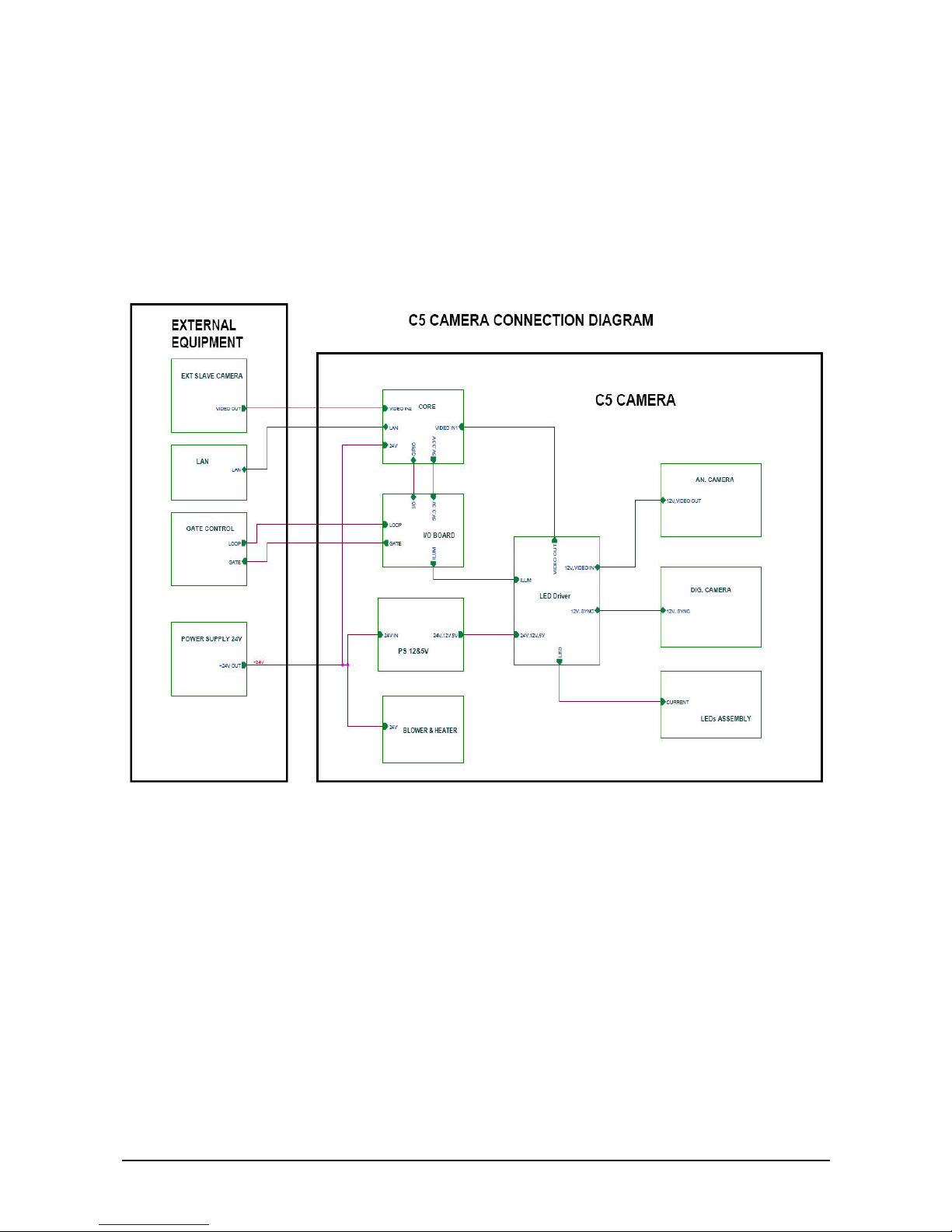
The C5 system architecture is illustrated in the following diagram. The inputs are a DC
adapter connected to the mains, and an optional dry-contact sensor indicating vehicle
presence, such as a loop detector. You can optionally use the unit’s internal motion
detection instead of an external trigger.
The optional output is the gate relay open signal, which can be used to open the gate for
authorized vehicles.
Figure 3: Block Diagram of C5 System

12 C5 System Components
C5 System Components
The C5 system contains the following main components:
♦ C5 unit.
♦ Power supply – 15 VDC, 50W, 110-220VAC power supply.
♦ External vehicle detector – Optional. A standard dry-contact sensor, such as a loop
detector. You can optionally use the C5 internal motion detector.
♦ Gate control – Optional. Controlled by the C5 output relay. The gate is opened for an
authorized vehicle only. This component is required only in an access control
installation.
System Software
C5 is shipped with pre-installed software components. The main pre-installed software
components include:
♦ C5 – Main application.
♦ cars.txt – Authorized cars database file. You can update the list of authorized cars, as
described in Editing the Authorized Cars List
.
♦ Format.ini – Country-specific license plates recognition information.
♦ C5.config – C5 configuration settings. You can edit the settings of the C5
configuration file, as described in Viewing and Changing the C5 Configuration File
.
C5 is an FTP server and can work with any FTP client, such as WinSCP. C5 is also an
SSH server and can work with any SSH client, such as PuTTY.
Software Integration in a Network
C5 can either operate as a standalone unit, or can connect to a central server using
“SeeData”, an HTS utility that is used for network connectivity.
SeeData can be installed on a central server. Each C5 unit can interface with SeeData.
When the unit is connected to a central server, the recognition result, including the image,
is sent over the network as a TCP/IP packet. It is intercepted by SeeData and converted
to a MSMQ message, which is supported by other HTS recognition systems, such as
SeeLane.
Each message contains:
♦ Recognition string.
♦ Date and time.
♦ Lane number – a unique ID for the lane, given by the user.
♦ Authorization information.
♦ Authorized Yes /No.
♦ Driver name if available.
♦ Optional image file path.

C5 Installation and Operation Guide Equipment Specifications Data sheets 13
Source code for sample client applications is available in VC++ and C# and can be
downloaded from the HTS support website. To test your client, refer to SeeData Interface
control document.
Host PC
The PC host is used for ongoing operations, such as updating the authorized cars list or
receiving results, and for installation and maintenance. Use any standard PC or laptop,
loaded with the necessary applications, connected via network communications.


C5 Installation and Operation Guide Installation and Initial Configuration 15
Chapter 3
Installation and Initial Configuration
Physical Installation
This section describes the physical installation of a single lane C5 system.
Installation Location Considerations
You can install C5 so that it will capture an image of either the front or rear of a vehicle.
The probable reasons for a rear installation include:
♦ Front installation is not possible due to traffic lane limitations. For example, the front
area is located in a public area in which no installation is permitted.
♦ Vehicles carry only rear license plates. This is true for most of the United States.
♦ Additional installation of a secondary camera in order to increase the recognition
coverage. In this case, two cameras are installed per lane. One is a C5, designated
the primary. The second camera has no internal CPU and is designated the
secondary. Typically, the secondary camera is the SCH3-IR for reflective plates and
the SCH3-Yellow for non reflective plates.
The dual-camera option (primary and secondary in dual enclosure) is not currently
supported.
Step 1 – Determining C5 Location
The location of C5 depends on whether you are installing it to capture an image of the
front of a vehicle or its rear.
Determining Front Installation Distances
♦ Install C5 2.5 meters from the barrier, in the direction of traffic, at the side of the lane
as near as possible to the lane. For non-reflective plates and USA size plates, install
C5 2 meters from the barrier (B in Figure 4).
♦ The distance from C5 to the license plate of the car should be 7.5 meters for a plate
length of 50 cm, or 6.5 meters for a plate length of 30 cm (A in Figure 4).
WARNING: A possible problem is that the barrier blocks the effective recognition
view zone, which is the area from the start of detection. In most gates, the
barrier’s height is 0.80 to 1.20 meters, so no blocking occurs. However, this
should be tested and avoided if necessary.

16 Physical Installation
♦ Try to install C5 as close as possible to the traffic lane, within 0.4 to 0.5 meters (C in
Figure 4). Do not install C5 so close that it can get damaged. You can install C5 on
either side of the traffic lane.
Figure 4: Front Installation Distances
If motion detection is used instead of a loop detector, the loop area in the
illustration indicates the desired area of detection.

C5 Installation and Operation Guide Equipment Specifications Data sheets 17
Determining Rear Installation Distances
♦ Install C5 4 meters from the loop detection line (B in Figure 5). This translates to about
9 meters or more from the front of the car since a typical vehicle is about 4 meters
long.
♦ Try to install C5 as close as possible to the traffic lane, within 0.0 to 0.5 meters (C in
Figure 5).
Figure 5: Rear Installation Distances
Step 2 – Installing C5
The recommended angle between C5 and the car is 15-16 degrees. The angle should not
exceed 30 degrees.
The camera should face downwards in order to minimize the sun effect. Since most plates
are mounted at a height of 0.20 to 1.25 meters, the recommended height for the C5 unit is
between 1 to 1.2 meters.
The maximum height at which the C5 should be installed is 3 meters. In this case, the
camera should be positioned such that the center of the vertical field of view is the trigger
area. For higher installations, consult Hi-Tech Solutions.

18 Physical Installation
You can mount the C5 unit on a wall, or install it on a pole or tripod. The following sections
provide installation instructions.
Mounting C5 on a Wall
Follow the instructions as indicated in the following illustrations:
Figure 6: Mounting C5 on a Wall

C5 Installation and Operation Guide Equipment Specifications Data sheets 19
Figure 7: Adjusting C5 Position and Direction
Figure 8: Location of Wall Mounting Holes for a C5 Camera

20 Physical Installation
Mounting a C5 Secondary Unit on a Wall
The secondary camera is typically the SCH3. Its mounting instructions are identical to the
instructions for mounting a C5 camera (see Mounting C5 on a Wall
). The only difference is
the location of the wall mounting holes (see Figure 9
).
Figure 9: Location of Wall Mounting Holes for a Secondary Camera
Mounting C5 on a Pole
To mount C5 on a pole, use the BR-20 pole adapter. The pole adaptor includes two straps
of different sizes to accommodate various pole circumferences.
1. Attach the pole adapter to the pole using one of the straps. Tighten the strap.
Figure 10: BR-20 Pole Adapter
2. Connect the bracket base of C5 to the pole adapter board. Use the three screws and
nuts provided in the pole adapter kit.
Figure 11: Screw Locations in the Pole Adapter

C5 Installation and Operation Guide Equipment Specifications Data sheets 21
Step 3 – Installing a Loop Detector
This step is relevant for an access-control system installation in which a loop detector is
used. Skip this step if you are installing an access-control system using the C5 internal
motion detector, or if you are installing a monitoring mode system.
It is assumed that the loop detector is a magnetic-loop detector type, about 1 m x 2 m.
Consult with HTS for recommended loop detectors. Follow the specific loop detector
instructions for exact installation instructions.
It is also advised to use speed bumps to slow down the traffic and to avoid bumper-tobumper cases which might cause detection failures. Consult HTS for a solution in these
cases.
Step 4 – Performing Electrical Connections
Perform the following electrical connections. Refer to Enclosure Wiring for details.
♦ Sensor/gate (optional input and output) – Connects to the sensors and gate. The two
pairs of connections are for the gate (output) and for the sensor (dry contact input).
♦ P/S Power Supply (input) – Gets 15 VDC from the power supply unit, which feeds
from the 100-200 VAC mains.
♦ LAN
– A wire or wireless network connection. Connects C5 to the network and
enables access to the C5 web-server and secure shell.
Step 5 – Fine Tuning the Loop Detector
It is recommended to use loop detectors with a fast response time of under 50 msec. For
details, refer to Ground Loops Specifications
.
Factory default settings are normally set to medium sensitivity. To fine tune the detector to
the size of the plate, increase and decrease the sensitivity.
♦ Increasing the sensitivity causes the loop detector to detect the vehicle when it is
relatively far. The result is that the plate looks relatively small in the captured image.
To decrease the plate size, increase the sensitivity.
♦ Decreasing the sensitivity causes the loop detector to detect the vehicle when it is
relatively close. The result is that the plate looks relatively large in the captured image.
To increase the plate size, decrease the sensitivity.
Initial Configuration
Connecting C5 to the Network
You should connect C5 to the network via a LAN or wireless connection, or both. This
section describes how to set up the initial connection to the network. If you wish to
subsequently change the network connection settings, refer to Changing Network
Connection Settings.
Regardless of the method you use to connect to the network, by the end of the process,
C5 will have an IP address. Write down the IP address since you will need it each time
you access the C5 portal to change C5 settings, such as to modify the authorized cars list.

22 Initial Configuration
Initial LAN Connection Configuration
f To connect C5 to the LAN for the first time:
1. Connect the PC/laptop to C5 using a LAN cable.
2. Set your PC/laptop LAN connection to IP address
192.168.0.54, mask
255.255.255.0.
3. Open any internet browser on your PC/laptop.
4. In the Web Address text box, enter the following:
192.168.0.55:4000/C5
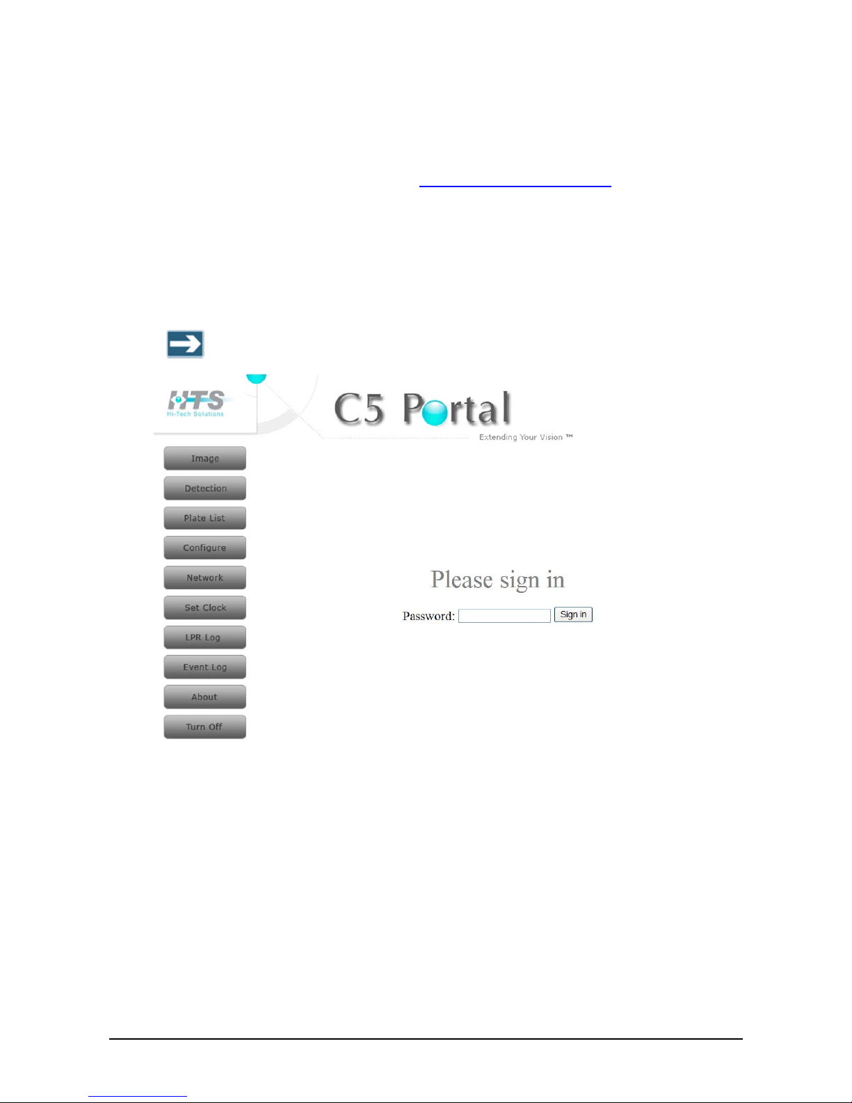
The C5 Portal home page appears (Figure 12).
5. Enter
1234 in the Password field, and click Sign in.
6. Click Network in the navigation pane on the left side of the C5 Portal home page. The
Network page appears (Figure 28).
7. In the Wired Network section, check the LAN checkbox to use static IP.
8. If you checked the LAN checkbox in the Wired Network section, perform the following
in that section:
a. Enter the C5 IP address in the IP field.
b. Enter a mask in the MASK field.
c. Enter an address for the gateway in the GATEWAY field.
9. Restart C5, as follows:
a. Click Turn Off in the navigation pane on the left side of the C5 Portal home page.
The Turn off page appears (Figure 13).
b. Click Restart. C5 shuts down and restarts.
10. Change the IP address of your PC/laptop LAN back to its original settings.
Initial Wireless Configuration
f To achieve wireless connection for the first time:
1. Set up a wireless network named C5WIRELESS.
2. Connect C5 to power.
3. Wait two minutes and try to ping C5.
Initial C5 Setup
C5 is configured using the C5 internal portal, which you can access using any internet
browser (see Accessing the C5 Portal
). Refer to C5 Setup for instructions on performing
the initial setup of the camera, its motion detection settings, etc.

C5 Installation and Operation Guide Using the C5 Portal 23
Chapter 4
Using the C5 Portal
The C5 Portal application is an integral part of the C5
supporting software and runs
internally in C5, and not on your PC/laptop. The C5
Portal is an intranet “web site”, which
can be viewed using any internet browser such as IE, Netscape, or Mozilla.
Using the C5 Portal, you can perform the following operations:
♦ In a dual-camera installation, specify which camera’s image to show in the C5 Portal
window.
♦ Specify an illumination level.
♦ Edit the Authorized Cars list.
♦ View the License Plate Recognitions log.
♦ Edit motion detection settings.
♦ View C5 images in real time.
♦ Change the C5 configuration file.
♦ Set C5 system time.
♦ View the C5 event log.
♦ Change C5 network connection settings.
♦ Restart or shutdown C5.
Using the portal is not recommended during normal operation
24 Accessing the C5 Portal
Accessing the C5 Portal
f To access the C5 Portal:
1. Make sure that you have already configured the C5 IP address and mask, and that it is
network-connected, as described in Connecting C5 to the Network
.
2. In a PC/laptop connected to the same network as C5, open any internet browser.
3. In the Web Address text box, enter the following:
http://<C5 IP address>:4000/C5
Where
<C5 IP address> is the IP address of C5.
The C5 Portal home page appears, with the main menu on the left.
The C5 Portal is best viewed at a screen resolution of 1024×768 pixels.
Figure 12: C5 Portal Home Page
4. Enter 1234 in the Password field, and click Sign in.
Logging Off the C5 Portal
f To log off the C5 Portal:
1. In the C5 Portal home page, click Turn Off. The Turn Off page appears
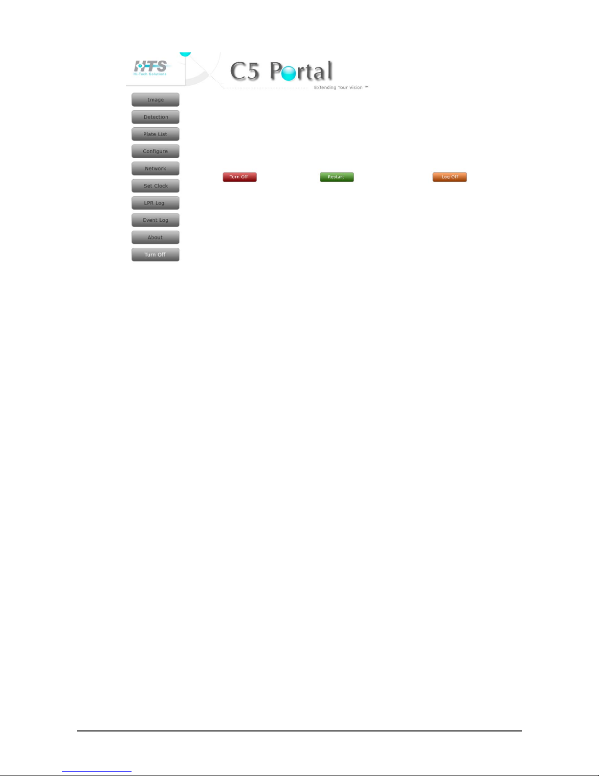
C5 Installation and Operation Guide Equipment Specifications Data sheets 25
Figure 13: Turn Off Page
2. Click Log Off. You are logged out of the C5 Portal.

C5 Installation and Operation Guide C5 Setup 27
Chapter 5
C5 Setup
This chapter describes basic C5 setup tasks.
Selecting a Camera
In a single-lane installation, the Image page displays the image taken by the single
camera.
In a dual-camera system, two cameras, a primary and a secondary, are installed in the
same lane. By default, the C5 Image page displays the image from the primary (local)
camera. You can specify which camera’s image to show.
f To specify which camera’s images are displayed in the Image page:
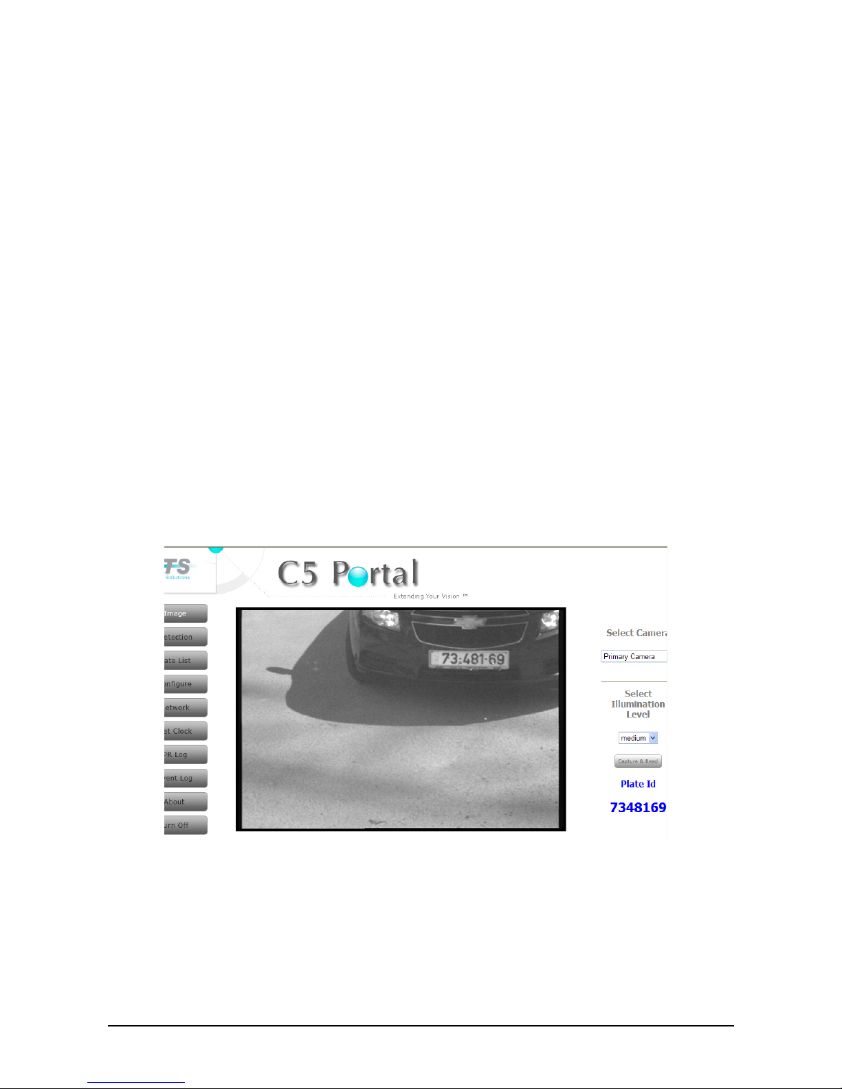
1. In the C5 Portal home page, click Image.
The Image page appears.
Figure 14: C5 Portal – Image Page
2. Select which camera’s images to show:
♦ Primary (local) Camera – local C5 camera.
♦ Secondary (remote) Camera –C5 second camera in dual enclosure configuration
or SCH-3 camera in stereo configuration when two cameras are separated to
supply a second point of view.

28 Selecting an Illumination Level
The secondary camera option is supported from application version1.0.0.1 and
O.S. Linux version 2.6.24 or higher.
The page option is available if VMD is disabled
Selecting an Illumination Level
Four levels of illumination are available.
f To specify the illumination level:
1. In the C5 Portal home page, click Image.
The Image page appears (Figure 14).
2. Select the illumination level: off – no illumination, low, medium or high illumination.
The illumination level option is supported only on the secondary camera, for the
primary camera it is not currently supported the illumination level is fixed.
C5 Installation and Operation Guide Equipment Specifications Data sheets 29
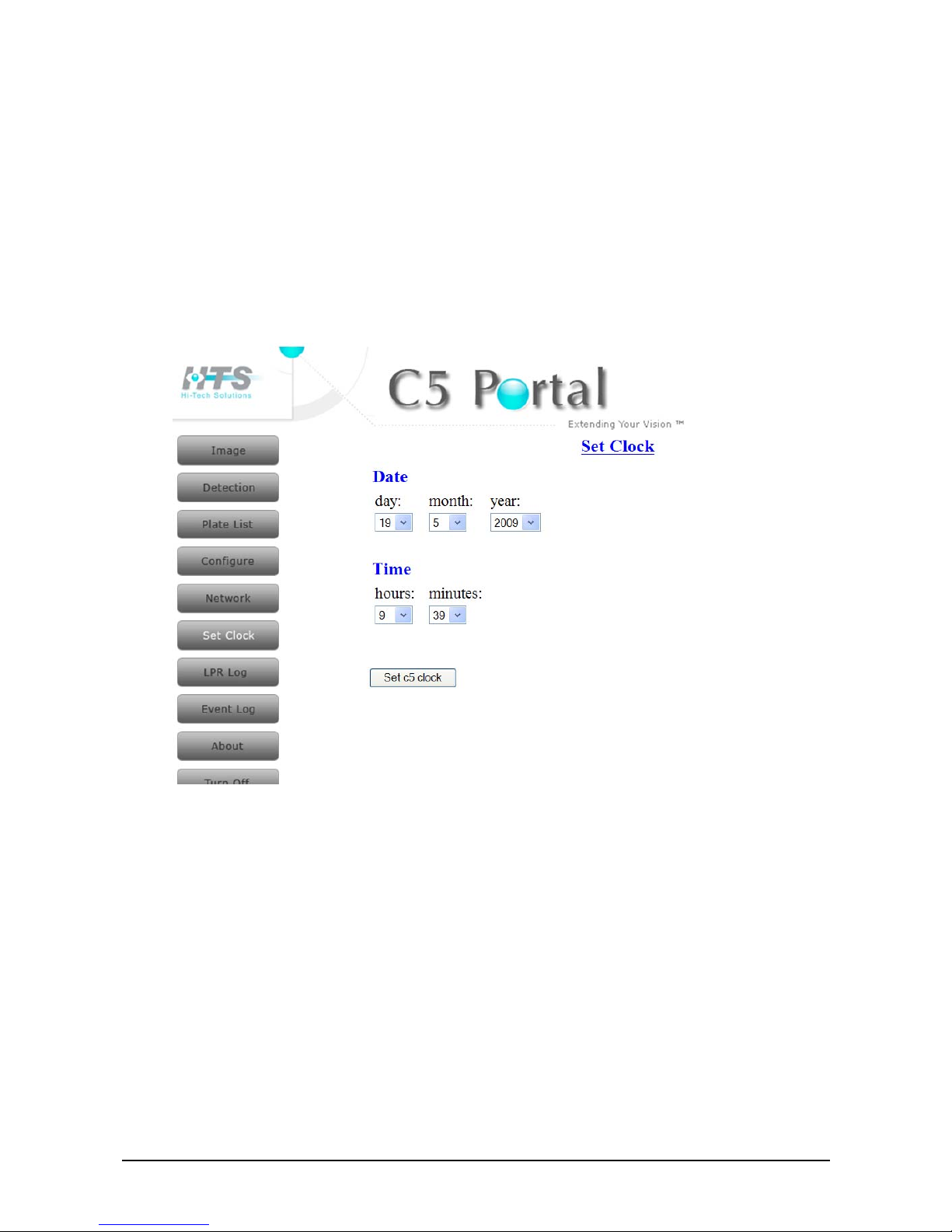
Setting System Date and Time
f To set the system date and time:
1. In the C5 Portal home page, click Set Clock.
The Set Clock page appears
Figure 15: Set Clock Page
2. Enter the desired date and time.
3. Click Set C5 clock.
The date and time are immediately updated.

30 Editing Motion Detection Settings
Editing Motion Detection Settings
This page is applicable only if you are using the C5 internal motion detector and not a
loop detector .
The Motion Detection page shows an image from the C5 camera with a red rectangle
representing the hot rectangle where Video Motion Detection (VMD) searches for
movement. Use the Motion Detection page to fine tune the location of the hot rectangle.
f To fine tune the hot rectangle for motion detection:
1. In the C5 Portal home page, click Detection. The Motion Detection page appears.
Figure 16: Motion Detection Page

C5 Installation and Operation Guide Equipment Specifications Data sheets 31
2. Specify the VMD settings as described in the following table:
Parameter Description
Enabled
Select this option if the system uses the internal motion detector to
detect motion.
Do not select this option if the system uses a loop detector to detect
motion.
Sensitivity The sensitivity level of the VMD algorithm.
Top
The distance in pixels from the top of the image, defining the top of the
hot rectangle.
Left
The distance in pixels from the left edge of the image, defining the left
edge of the hot rectangle.
Right
The distance in pixels from the right edge of the image, defining the
right edge of the hot rectangle.
Bottom
The distance in pixels from the bottom of the image, defining the
bottom of the hot rectangle.
Important: VMD settings take effect only after restarting C5.
Refer to Restarting C5
.
Restarting C5
f To restart C5:
1. In the C5 Portal home page, click Turn Off. The Turn Off page appears (Figure 13).
2. Click Restart. C5 shuts down and restarts. After about 2 minutes it is up again.
Note that any change in parameters requires application restart.
Click "Restart" button on each relevant page.
Shutting Down C5
f To shut down C5:
1. In the C5 Portal home page, click Turn Off. The Turn Off page appears (Figure 13).
2. Click Turn Off. C5 shuts down.
To start C5, disconnect and reconnect it to the mains.

32 Editing the Authorized Cars List
Chapter 6
Managing the Authorized Cars List
This chapter describes how to manage the Authorized Cars list.
Editing the Authorized Cars List
The Cars List page of the C5 portal shows the list of authorized cars. You can add a new
member to the list, edit the details of an existing member in the list, or remove members
from the list.
Figure 17: Cars List Viewer & Editor Page
Adding a Car to the Authorized Cars List
f To add a car to the Authorized Cars list:
1. In the C5 Portal home page, click Plate List.
The Cars List page appears (Figure 17).
2. Click Add Member. The Add Member dialog box appears.

C5 Installation and Operation Guide Equipment Specifications Data sheets 33
Figure 18: Cars List Page – Add Member Dialog Box
3. In the Add Member dialog box, enter the relevant data for the car you are adding, as
described in the following table. You must at least enter the car’s license plate number
in the Car License Number field.
Parameter Description
Car Number The car’s license plate number, as it appears on the license plate.
First Name The first name of the person owning the car.
Last Name The last name of the person owning the car.
4. Click Add to list. The new record appears in the Authorized Cars list.
Editing the Details of a Car
f To edit car details in the Authorized Cars list:
1. In the C5 Portal home page, click Plate List.
The Cars List page appears (Figure 17).
2. Click Edit Member. The Edit Member dialog box appears.
Figure 19: Cars List Page – Edit Member Dialog Box
3. Select a record from the Choose a record drop-down list.
4. In the Edit Member section, edit the data of the car you selected, as described in the
following table.
Parameter Description
Car Number The car’s license plate number, as it appears on the license plate.
First Name The first name of the person owning the car.
Last Name The last name of the person owning the car.
5. Click change. The revised record appears in the Authorized Cars list.

34 Editing the Authorized Cars List
Removing a Car from the Authorized Cars List
f To remove a car from the Authorized Cars list:
1. In the C5 Portal home page, click Plate List.
The Cars List page appears (Figure 17).
2. Click Remove Member. The Remove Member dialog box appears.
Figure 20: Cars List Page – Remove Member Dialog Box
3. Select a record from the Choose a record drop-down list.
4. Click Remove. The specified car is removed from the Authorized Cars list.
License plate is primary DB key; hence same plate number cannot be
added twice. However it is possible to add same person name with
several plate numbers.

C5 Installation and Operation Guide Equipment Specifications Data sheets 35
Viewing the License Plate Recognitions Log
The LPR log file saves license plate recognitions up to a log file size of 50Kb. Once the
size of 50Kb is reached, a new log file is created, and the old one is saved as history.
f To view the License Plate Recognitions log:
1. In the C5 Portal home page, click LPR Log.
The LPR Log page appears, enabling you to view the content of the old LPR log and
the new LPR log.
Figure 21: LPR Log Page
To clear the LPR log, click Clear Log.
To refresh the LPR log, click Refresh.


C5 Installation and Operation Guide Real Time Monitoring 37
Chapter 7
Real Time Monitoring
This chapter describes how to monitor the lane by viewing C5 images in real time.
Viewing Real Time Images
f To view C5 real time images:
1. In the C5 Portal home page, click Image.
The Image page appears, showing real time images from the camera (Figure 14).
f To check license plate recognition:
1. Click Capture & read. A new image is taken and the license plate string is processed
for identification. The identified license plate string appears under Plate Id in the lower
right corner of the page.
If your browser doesn’t change the image on the page when you click Capture &
read, follow the instructions in Editing the Browser Capture Settings
to change the
browser settings so that a new image is loaded every time you click Capture &
read.
Editing the Browser Capture Settings
If your browser doesn’t change the image on the page when you click Capture & read in
the Image page, change the browser settings. Otherwise, you must refresh the Image
page every time you capture an image.
f To change the browser settings:
1. Select Tools Æ Internet Options in your browser. The General tab appears.

38 Viewing Real Time Images
Figure 22: General tab of the Internet Options Page (in the local browser)
2. Click Settings in the Temporary Internet files section. The Settings dialog box
appears.
Figure 23: Temporary Internet Files – Settings Page (in the local browser)
3. In the Settings dialog box, select on every visit to the page.
Now, every time you click Capture & read a new image is taken and displayed in the
window.
C5 Installation and Operation Guide Viewing and Changing the C5 Configuration File 39
Chapter 8
Viewing and Changing the C5
Configuration File
The C5.config file is the C5 configuration file. You can edit the parameters in the file
using the C5 Portal. The changes take effect immediately after submitting them. Most of
the parameters are pre-limited to the correct range, but there are some “open” parameters
that should be configured only as described in this section.
Viewing and Changing General Parameters
f To view and change general C5 parameters:
1. In the C5 Portal home page, click Configure.
The Configure page appears.
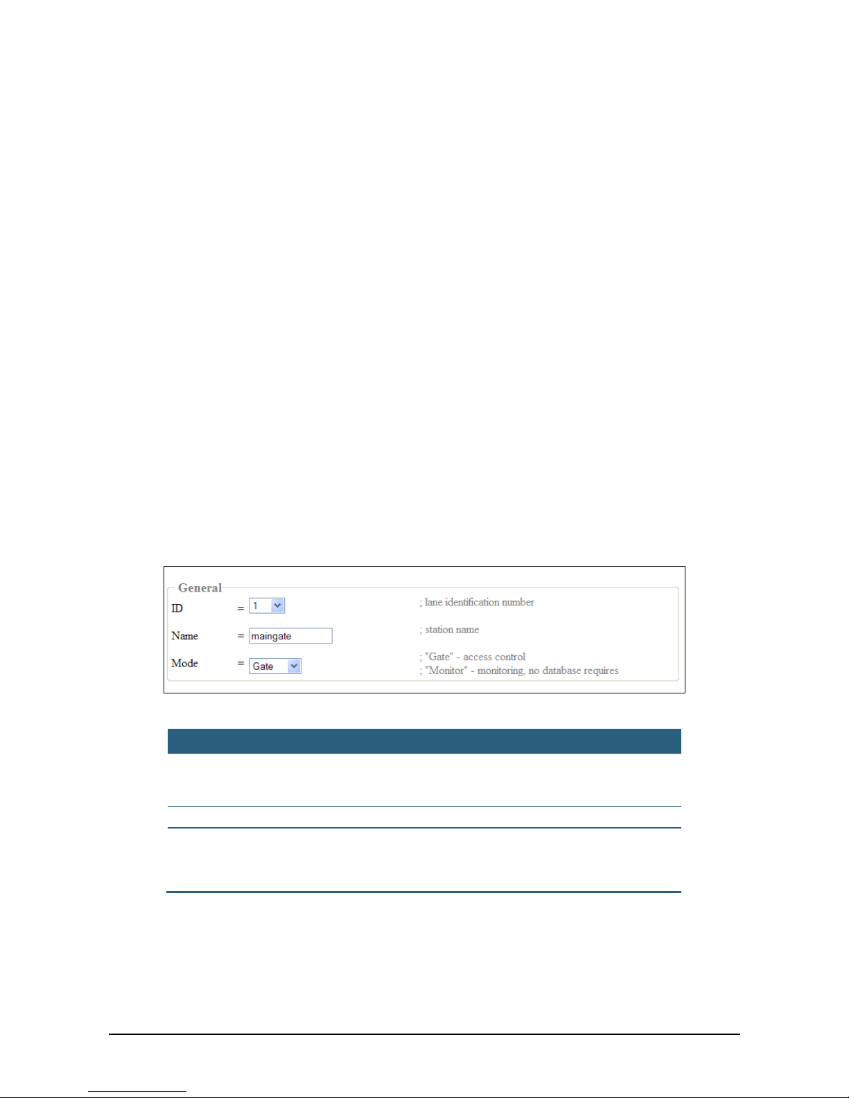
2. In the General section, view or change the settings, as described in the table below.
Figure 24: Configure Page – General Parameters
Parameter Description
ID The ID number of the lane.
This field is intended for multi C5 installation sites. In such
installations, assign a different ID to each C5 unit.
Name A free text field. Generally used to describe the C5 location.
Mode The mode of operation:
♦ Gate – Access Control with gate.
♦ Monitor – Report only.

40 Viewing and Changing Monitoring Parameters
Viewing and Changing Monitoring Parameters
This section is relevant for a system in monitoring mode.
f To view and change C5 monitoring parameters:
1. In the C5 Portal home page, click Configure.
The Configure page appears.
2. In the Monitoring section, view or change the settings, as described in the table below.
Figure 25: Configure Page – Monitoring Parameters
Parameter Description
Confidence
The minimal recognition confidence level allowed for the entire
license plate string.
Range: 50 – 100.
minMark
The minimal recognition confidence level allowed for each
individual character. Below this percentage of confidence in the
recognition, the individual character is replaced by “.”.
Range: 0 – 100.
C5 Installation and Operation Guide Equipment Specifications Data sheets 41
Viewing and Changing Local Camera
Parameters
The local camera is the primary camera in a dual-camera installation.
In a single-camera installation, local camera refers to the single C5.
f To view and change local camera parameters:
1. In the C5 Portal home page, click Configure.
The Configure page appears.
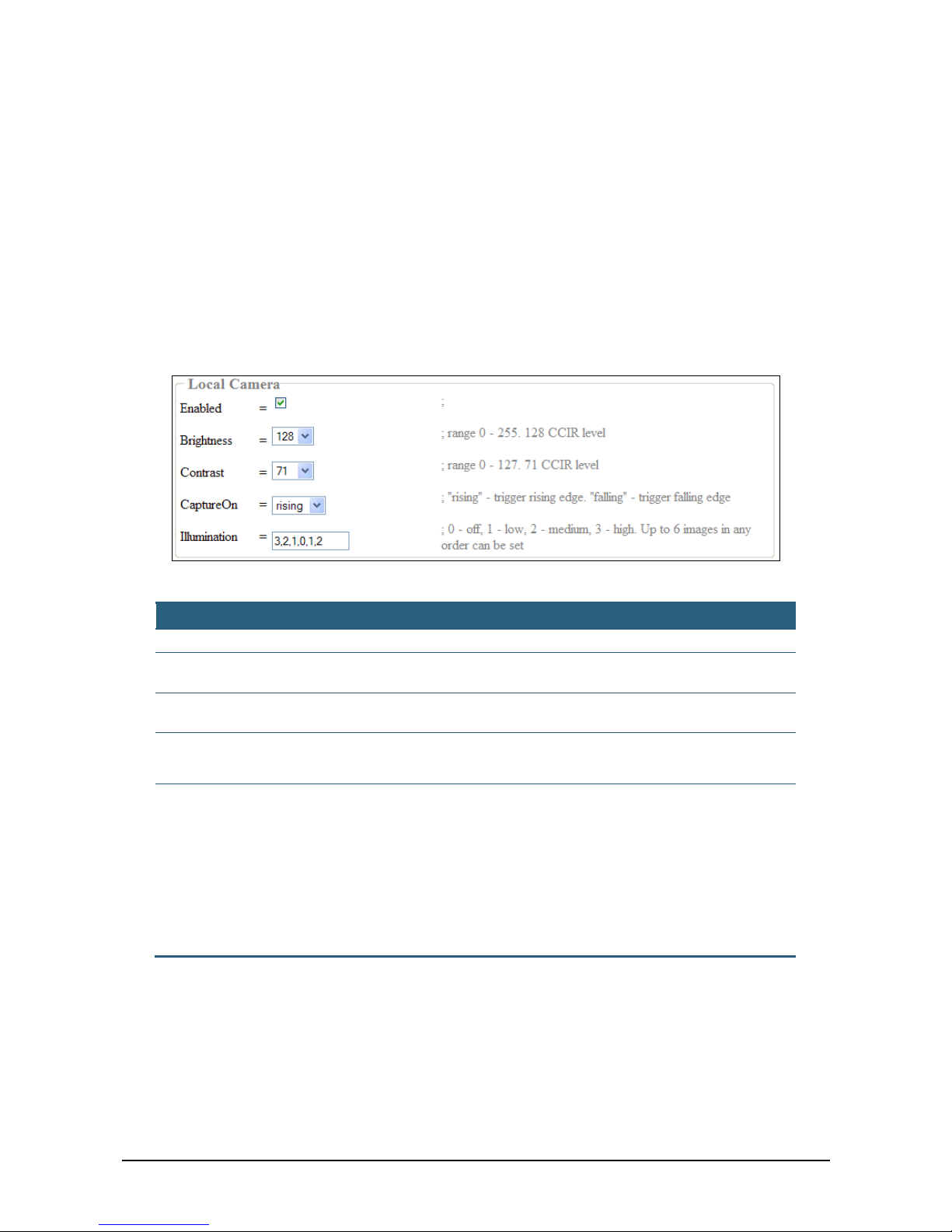
2. In the Local Camera section, view or change the settings, as described in the table
below.
Figure 26: Configure Page – Local Camera Parameters
Parameter Description
Enabled Select this option if there is a Local camera (primary camera).
Brightness
Range: 0-255.
Default: 128.
Contrast
Range: 0-127.
Default: 71.
Capture On
♦ Rising – Trigger on rising edge.
♦ Falling – Trigger on falling edge.
Illumination
Set the number of images the camera will capture. Each image is
represented by its illumination level (0-3):
♦ 0 – Off.
♦ 1 – Low.
♦ 2 – Medium.
♦ 3 – High.
Up to 6 images separated by commas in any illumination order can be set. If
the field is empty, six images will be captured as follows: 3,3,2,2,1,1.

42 Viewing and Changing Remote Camera Parameters
Viewing and Changing Remote Camera
Parameters
The remote camera is the secondary camera in a dual-camera installation.
The option for dual-camera enclosure is not currently supported.
f To view and change remote camera parameters:
1. In the C5 Portal home page, click Configure.
The Configure page appears.
2. In the Remote Camera section, view or change the settings, as described in Viewing
and Changing Local Camera Parameters. The only difference is that the Enabled
checkbox refers to the remote camera, not the local camera.
Viewing and Changing Network Client
Parameters
f To view and change C5 network client parameters:
1. In the C5 Portal home page, click Configure.
The Configure page appears.
2. In the Net Client section, view or change the settings, as described in the table below.
Figure 27: Configure Page – Net Client Parameters
Parameter Description
Enabled
If this option is selected, the result and the best image will be sent
to the SeeData application on a PC/laptop connected to the same
network.
ServerIP The IP address of the PC/laptop that runs the SeeData application.
Port The TCP/IP port to connect to the PC/laptop.
In the case of changing network parameters (IP address) the whole
system must be restarted and it will cause current portal session
disconnection.

C5 Installation and Operation Guide Viewing and Changing the C5 Configuration File 43


C5 Installation and Operation Guide Changing Network Connection Settings 45
Chapter 9
Changing Network Connection
Settings
You can change your network connection settings whether C5 is connected to the
network via a LAN or via a wireless connection.
Changing LAN Connection Settings
f To change the LAN connection settings:
1. In the C5 Portal home page, click Network. The Network page appears.
Figure 28: C5 Portal – Network Page
2. Change the settings in the Wired Network section according to the explanations in the
table below.
Parameter Description
Lan
Select this option if you wish to use the IP, MASK, and GATEWAY
settings for network connectivity.
If this option is not selected, DHCP is used.
IP The IP address.
MASK The mask.
GATEWAY The address of the gateway.

46 Changing Wireless Connection Settings
Changing Wireless Connection Settings
f To change the wireless connection settings:
1. In the C5 Portal home page, click Network. The Network page appears (Figure 28).
2. Change the settings in the Wireless Network section according to the explanation in
the table below.
Parameter Description
Wireless
Select this option if you wish to use the wireless settings for
network connectivity.
If this option is not selected, DHCP is used.
Net Name The wireless network name
Important: Any change in network properties will affect the system only after a
restart.

C5 Installation and Operation Guide Camera Adjustment 47
Chapter 10
Camera Adjustment
After the system is installed, you must adjust the camera. The adjustments ensure that the
cameras are aimed at the desired field of view, the video displays high quality images,
and the system recognizes the license plates at a high success rate.
f To adjust the camera:
1. Use a vehicle with a front plate for front LPR and a vehicle with a rear plate for rear
LPR. For front LPR, position the vehicle before the ground loop. To pinpoint vehicle
location, ask the driver to drive slowly until you see the trigger LED in the ground loop
controller. Make sure the vehicle is in the center of the loop’s width.
If you are using the C5 internal motion detector, the vehicle position for the test should
be the same location as the one you would use for a ground loop.
2. Log into the C5 Portal as described in Accessing the C5 Portal
.
3. View real time images as described in Viewing Real Time Images
.
4. Adjust the camera so that the plate is in the center of the image. Since the vehicle
moves and we want to capture the plate in the second, third, …., N images, adjust the
camera as follows:
♦ For front LPR – In the first image, the plate should appear at the top of the image.
♦ For rear LPR – In the first image, the plate should appear at the bottom of the
image.
Figure 29: Plate Location in the First Image for Front and Rear LPR
5. If you are using vari-focal lens, zoom the lens to a distance where the plate is covered
by 150 pixels. Make sure the width of the field of view is at least 1.8 m.
6. Make sure the characters on the plate are focused.
7. In the C5 portal Image page (Figure 14), click Capture & read. The system captures
an image and recognizes the plate number. Make sure the recognition is correct.
Repeat the process several times.
If you installed more than one camera per lane, perform the same test for the
secondary camera. Select the secondary camera (remote camera) in the Image page,
and perform the same test steps.

48 Changing Wireless Connection Settings
8. In the SeeData application, open Settings and check File Transfer. The system will
now save all the captured images. You can also optionally change the location of the
saved images.
9. Instruct the driver to drive the vehicle on the left side of the lane, on the right side, and
in the middle. Instruct the driver to repeat this at different speeds.
After each drive, check the images in the images folder. The goal is to capture as
many images as possible which show the license plate clearly. If the system is
configured to capture six images, all six should include the plate.
It is recommended to configure the system to capture images with different illumination
intensities. Check the images to see the plate in different light conditions.
If the camera is installed on a gantry and the system is set up for front LPR, then when
the vehicle is driven down the middle of the lane you should get x images with closer
and closer plates:
Figure 30: LPR When C5 Installed on a Gantry
If the camera is installed on a pole and the system is set up for front LPR, then when
the vehicle is driven down the middle of the lane you should get x images with closer
and closer plates moving diagonally:
Figure 31: LPR When C5 Installed on a Pole
10. Once the results are satisfactory, run a large-scale test. Use as many different
vehicles as you can. Drive them 20-30 times at different speeds and in different lane
positions. Check the results, and fix any problems found.

C5 Installation and Operation Guide Acceptance Test 49
Chapter 11
Acceptance Test
Perform the tasks listed in Installation Verification Checklist to verify that the site is
properly installed.

C5 Installation and Operation Guide Troubleshooting and Support 51
Chapter 12
Troubleshooting and Support
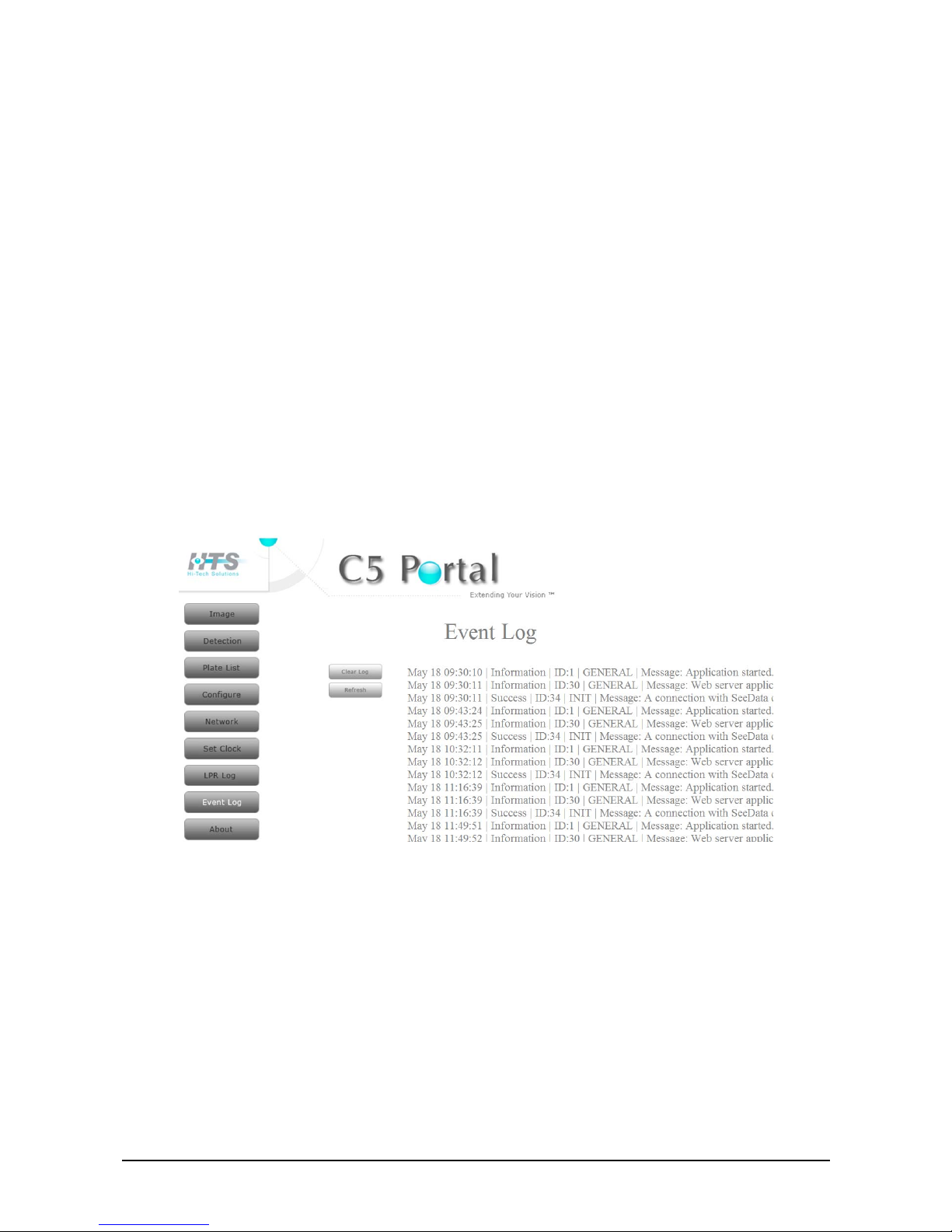
Viewing the Event Log
The C5 event log is an important troubleshooting tool. If an error occurs, the event log is
helpful in analyzing the reason and solving the problem.
f To view the event log:
11. In the C5 Portal home page, click Event Log.
The Event Log page appears, displaying the event log content.
Figure 32: Event Log Page
Every event message has the following format:
< Month >< Day >< Hour >|< Event Type >|< Event ID >|< Event Type >|< Message >

52 Contact Information
Contact Information
You can contact us for more information and assistance at:
R&D and Support Marketing and sales
6 Tikshoret St.
Ramat Gavriel Industrial Park
Migdal HaEmek 23100
Israel
Tel:+972-4-6441869
Fax: +972-4-6441870
s
upport@htsol.com
3 Shimon Israeli St.
New Industrial Zone
Rishon Le-Zion 75144
Israel
Tel: +972-3-9634601
Fax: +972-3-9634576
info@htsol.com
C5 Installation and Operation Guide Equipment Specifications Data sheets 53
Appendix A
Equipment Specifications Data sheets
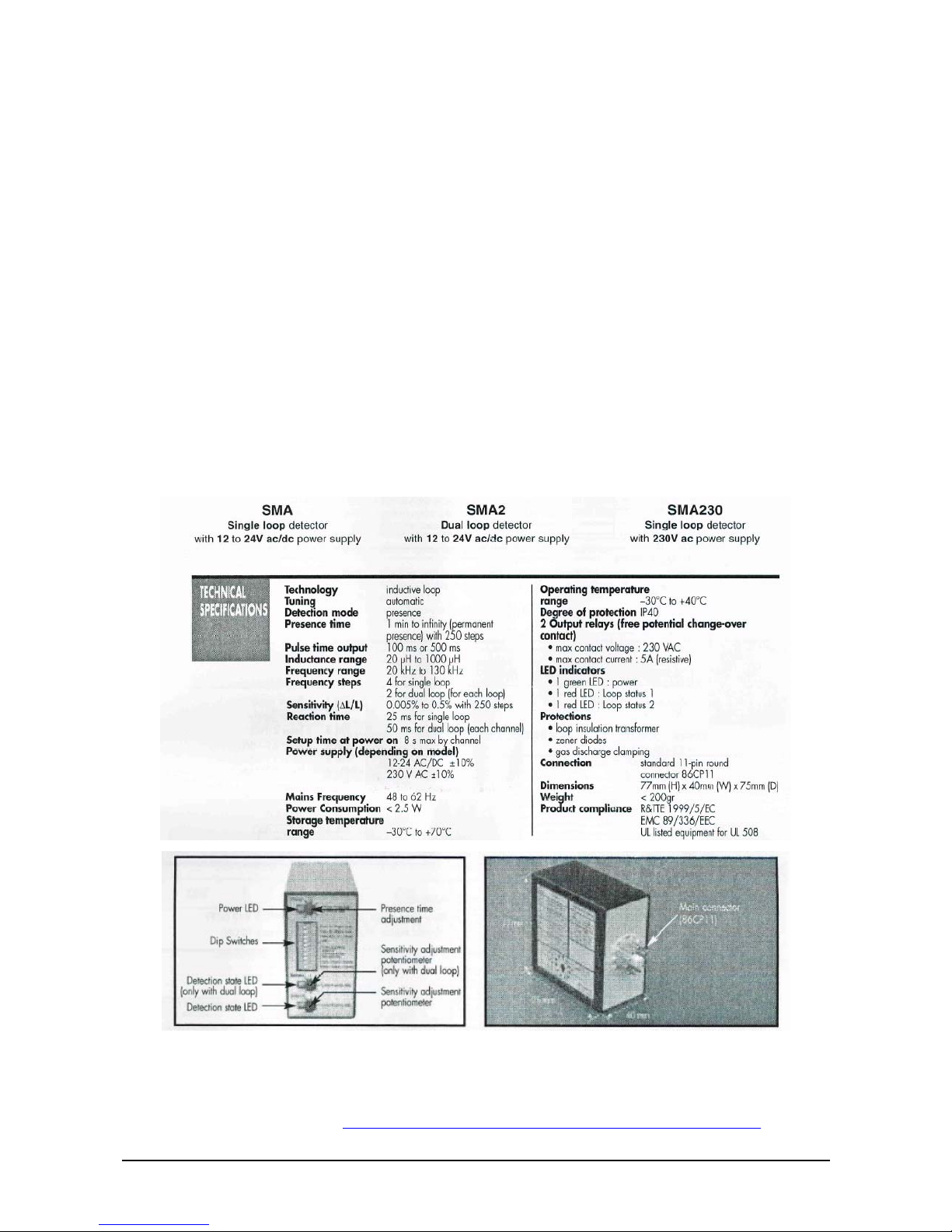
Ground Loops Specifications
The following sections provide details about the Came SMA loop detector and the Matrix
loop detectors.
Came SMA Datasheet
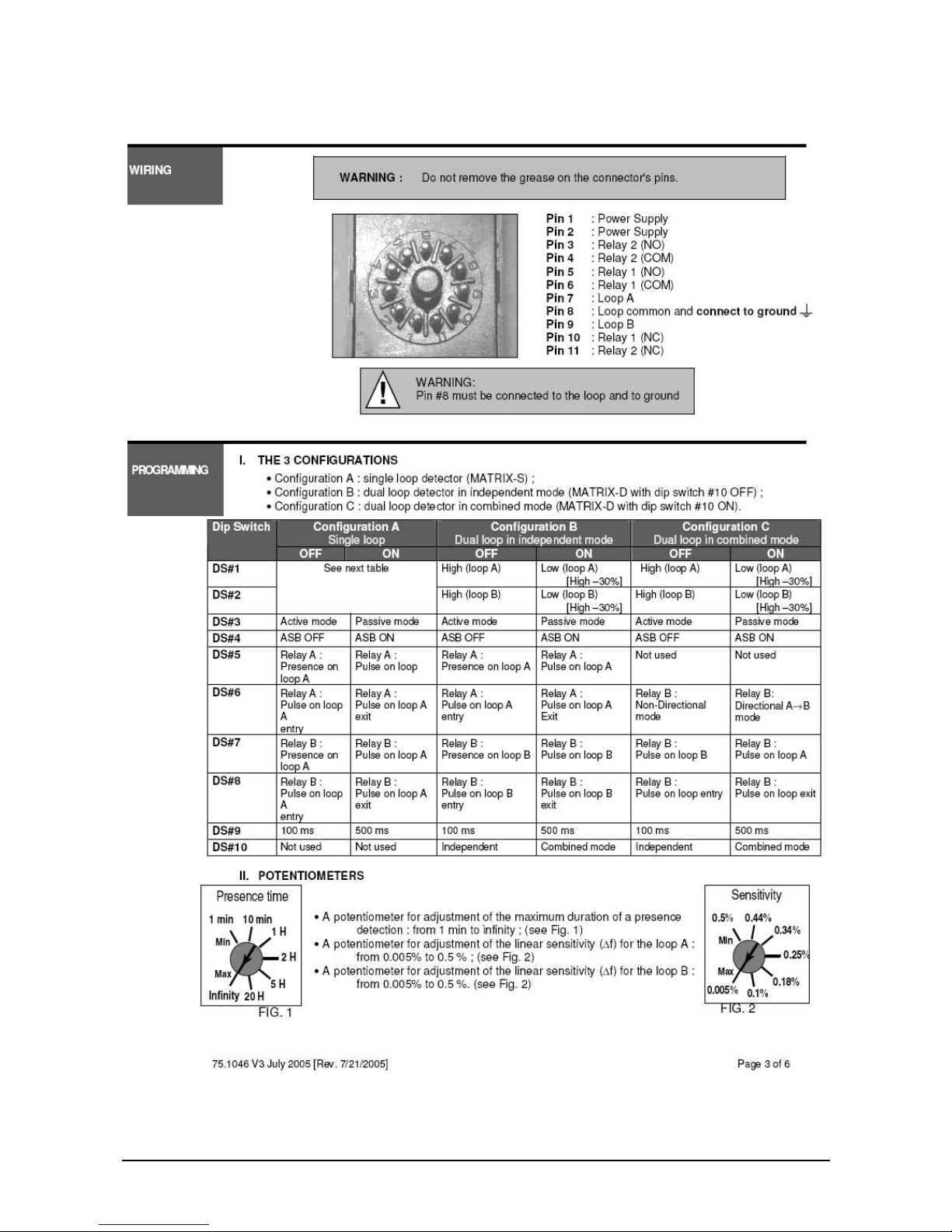
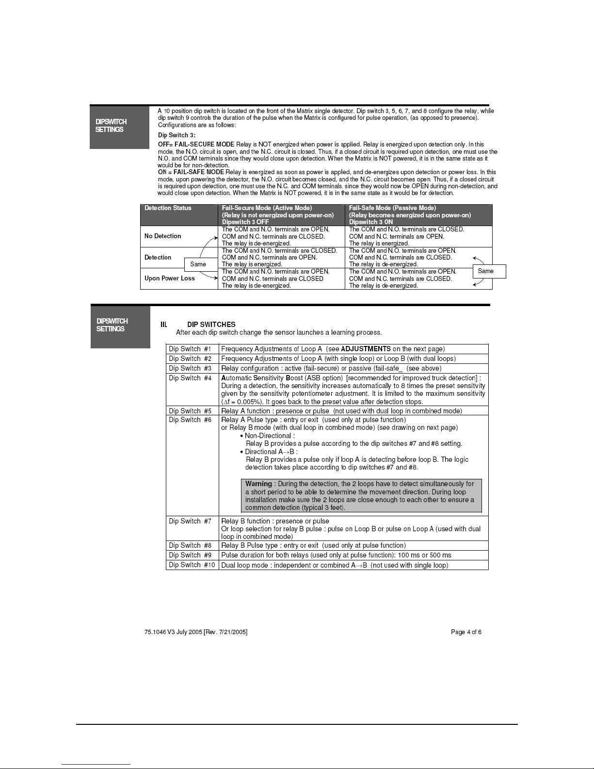
Matrix Ground Loop User guide
The following pages are datasheets pages of the Matrix ground loops user guide. For
more details, refer to: http://www.beainc.com/beainc/Downloads/Products/Matrix/
.

54 Ground Loops Specifications

C5 Installation and Operation Guide Equipment Specifications Data sheets 55
56 Ground Loops Specifications
C5 Installation and Operation Guide Equipment Specifications Data sheets 57

58 Ground Loops Specifications

C5 Installation and Operation Guide Equipment Specifications Data sheets 59

60 Ground Loops Specifications
Appendix B
Enclosure Wiring
Connecting C5 secondary camera
The C5 unit is supplied with external cables; connect each cable to his function as follows:
i. Utility cable for C5 (Power, Loop, and Gate), 5m length includes:
a) Power Supply
Red wire for +15VDC
Black Wire for Ground
b) Gate Relay output:
Brown fir for common Gate(COM)
Blue wire for Normally Close (N.C.)
Yellow for Normally Open (N.O.)
c) Loop connector input:
Green wire for LOOP Common
White wire for LOOP
ii. Ethernet LAN Cable (RJ45 male connector), 5m length Shielded.
Connecting secondary camera in stereo mode
Additional 3 wire cable for external secondary camera is connected to the Secondary
camera (connect VIA terminal block) includes Illumination control input:
White wire connect to secondary LSB white wire
Green wire connect to Secondary MSB Green wire
Black wire connect to Secondary Black wire
Power supply (secondary camera has its own power supply) use the same terminal
block for connecting the two wires:
Red wire for +15VDC
Black Wire for Ground shared with the Black wire connect to Secondary Black
wire
It is important to connect all ground wires together.
C5 Installation and Operation Guide Enclosure Wiring 61
The following diagram shows C5 wiring.
Figure 33: C5 Wiring


C5 Installation and Operation Guide Sample Bill of Material 63
Appendix C
Sample Bill of Material
The following table shows the operational bill of materials for a typical basic installation
with IR illumination.
Component HTS Part #
Camera C5 IR C5000016500SK
Power Supply 15V Set (including Cable and adaptor) PS15VSETUSA / EUR
Utility cable for C5 (Power, Loop, and Gate), 5m length 511015
Ethernet Cable (RJ45, Shielded), 5m length 560229
Null modem cable, DB9 (F) TO RJ11, 2m, p/n 504F010030
(optional)
511067
The following table shows the operational bill of materials for a typical basic installation
with yellow illumination.
Component HTS Part #
Camera C5 Yellow C5000016500EL
Power Supply 15V Set (including Cable and adaptor) PS15VSETUSA / EUR
Utility cable for C5 (Power, Loop, and Gate), 5m length 511015
Ethernet Cable (RJ45, Shielded), 5m length 560229
Null modem cable, DB9 (F) TO RJ11, 2m, p/n 504F010030
(optional)
511067
The default BOM is for customers who purchased basic system (without
VMD). Customers who purchased basic system should Contacts HTS for
upgrade the system to full version (with VMD).


C5 Installation and Operation Guide Installation Verification Checklist 65
Appendix D
Installation Verification Checklist
# Group Test or Verify Test Methods and
Expected Results
Pass /
Fail
Comments
1 Power
The power supply is installed
and running.
Visual observation.
Verify that the power LEDs
are ON on the power supply
and inside the camera
housing power board.
The UPS is installed,
powered, and connected.
Unplug the UPS power cord
and verify that C5 is awake.
Optional
Loop Controllers are wired
and powered by the main
power in the cabinet and on
the I/O Board.
Visual observation.
Verify power LEDs are ON
the power supply and inside
the camera housing I/O
board.
All cameras are connected to
the power supply.
Visual observation.
Verify that the camera power
LEDs are on.
All cameras are connected to
the LAN connection inside the
camera.
Visual observation.
Verify that the camera power
LEDs are on.
2 Software C5 Portal is up.
Operate the C5 portal by
navigating to the web site.
3
Ground Loop
and
Ground Loop
Controllers
Loop Controller
Activate it by driving on the
ground loop.
The ground loop is installed
according to manufacturer
datasheet (number of turns,
dimensions, etc.).
Optional
The ground loop controller
shows activity (LED) when it
is activated.
The ground loop controller is
working in presence mode.
4 I/O Card
Wires have labels and are
tightened to enclosure at I/O
board.
Function
Click image and check the
two green LEDs on I/O
board lighting per
illumination levels operating.
5 Camera For each camera:
Go to image page in the
Portal main page option.
Camera is on.
Camera is mounted to the
wall or to a pole with correct
bolts.

66 Ground Loops Specifications
# Group Test or Verify Test Methods and
Expected Results
Pass /
Fail
Comments
To control the illumination
intensity, right-click and
change levels.
The test should be done
against a reflecting plate.
Camera is looking towards
the middle of the loop.
Video quality is good.
Smooth video stream with
no noise.
All illumination intensities
work properly.
6 Network Net client connectivity
Write in the configure
section net client (checked)
for enable add IP number
(1368 is our default) restart
and check in data center the
IP is connected.

C5 Installation and Operation Guide Software Update 67
Appendix E
Software Update
This chapter describes how to update C5 software.
Updating C5 Software
f To update the C5 software:
1. Use an FTP client, such as WinSCP, to transfer the upgrade files to
/home/hts.
2. Open an SSH connection to C5, using an SSH client such as PuTTY.
3. In the terminal window, enter the following commands:
cd /home/hts
chmod 777 *
chown root:root *
shutdown –rF now
The software upgrade will take effect after C5 restarts.
Contact support before updating C5 Software or operating system


C5 Installation and Operation Guide Document History 69
Appendix G
Document History
Versi
on
#
Version Date Technical
Writer
Document
Author
Comment
Sections
Affected
Reviewed
By
1.0 9‐ June, 2009 Yael Klein
IFN solutions
Doron Almagor New document
All
Review by
R&D
1.1 29‐ Sept, 2009 Yael Klein
IFN solutions
Doron Almagor 1. Led safety warning symbol
2. Update images 14, 16,
3. update for dual camera
4. change terms of master & slave cameras to
primary & secondary cameras;
5. Updating drawings for vehicle positioning
6. Update loop drawing
7. Add doc. History appendix.
Page 6
Chapter 5
Appendix G
Review by
R&D
1.2 2‐Feb, 2010 Doron Almagor Doron Almagor
1. Explains on two available (version)
configurations: basic (without VMD) and full.
2. PC host must be removed from C5 System
components, page 12.
3. Software Integration chapter DDE replaced
within MSMQ
4. Note using web portal is not recommended
during system normal operation.
5. Add note system must be restarted and it will
cause current portal session disconnection.
6. In "Adding a Car to the Authorized Cars List –
“same plate cannot be added twice”
7.update appendix "Enclosure Wiring".
8. Update "Sample Bill of Material" appendix.
9. Review "Installation Verification Checklist"
All
Review by
R&D and
Support
 Loading...