

Page 1
NEON-SS FM
INSTRUCTION MANU AL
FM
www.hitecrcd.com
Page 2
1 Introduction
Congratulations, you now own one of the most unique and revolutionary radio control systems in the w orld.
The Neon 3 was created for the beginner and seasoned R/C enthusiast to grow with your needs and skill level.
The basic Neon can be upgraded with a variety of features like;
- A 4th channel three position switch - Dual Rates on channels 1 and 2
- ATV's on channel 1, 2 and 3 - A trainer port and switch package
Any way you choose to customize your Neon, y ou are sure to be satisfied with the performance on this unique system.
T able of contents
1. Introduction
2. Features and Specifications
Page 2
Page 3
Page 4
Page 5
Page 6
Page 7
Page 8
Transmitter
Options
3. System Components
Receiver
Servo (Standard version, Micro version)
Accessories, all systems
4. Set-up and Operation
Transmitter
Reading the LED Battery Indicators
Recharging Nicad batteries
Installing Transmitter Batteries
To install or change the batteries in your NEON
Transmitter antenna
Elevon/V-tail mix
Servo Reversing
Gimbal stick length adjustment
Gimble stick tension adjustment
Throttle Function
5. Installation of Receiver and Servos
Turning on your system
Servo trim settings
Range check
Checking servo operation
6. NEON Transmitter Option Installation Directions
Trainer Port and Switch Installation
ATV Board Installation
Dual Rate Switch Installation
4th Channel Three Position Switch Accessory Installation
2 Fea tures and Specifications
T ransmitter
- Single Stick 3 channel, (upgradeable to
4 channel) FM proportional system
- Dual axis precision gimbal
- Adjustable gimbal stick length
- Adjustable gimbal stick tension
- 3 LED battery status indicators
- Charging jack for optional internal Nicad battery
- Servo rev ersing for all channels
- Elevon or V -tail mixing function
- Proportional 3rd. channel slide switch
- Channel 1 and 2 trim levers
Options
- Channel 4 three position switch, part # 54301
- Channel 1,2 and 3 ATV function, part # 54302
- Trainer plug and switch, part # 54303
- Channel 1 and 2 Dual Rate function part # 54304
(Must use optional part# 54304, ATV function in
addition to this option)
2
Page 3
3 System Components
Receiver
Currently there are two popular receivers used in the Neon 3 packages.
Deluxe Version includes : Electron 6 channel Dual Conversion 6 channel FM receiver
-Size:45.5x22.5x15.0(mm)/1.79x0.88x0.59(inch)
- Weight : 17g(0.6oz) without X-tal
Micro version includes : HFS-04MG 4 channel Single Conversion 4 channel FM receiver
- Size: 25 x 37.5 x 16 (mm) / 0.98 x 1.47 x 0.62 (inch)
- Weight : 15.9g (.55oz)
Servo
Currently there are two popular servos choices offered in the Neon 3 packages.
Deluxe Version includes : (2) HS-81 micro servos
- Speed : .11(4.8V) /.10sec(6.0V)
- Torque : 2.6(kg/cm) / 36oz at 4.8V
3.0(kg/cm) / 41oz at 6.0V
-Size : 30x12x30(mm)/1.2x0.47x1.2(inch)
- Weight : .58oz/16.6g
Micro version includes :(2) HS-55 sub-micro servos
- Speed : .17(4.8V) /.14sec(6.0V)
- Torque : 1.1(kg/cm) / 15oz at 4.8V
1.3(kg/cm) /18oz at 6.0V
-Size : 23x12x24(mm)/0.90x0.45x0.94(inch)
- Weight : .28oz/8.0g
Accessories
One CG-25 or CG-22A overnight wall charger, part # 43025 or # 43022
One Switch harness, part # 54403
One AAA receiver battery box, part # 54402
4 Set-up and Operation
T ransmitter
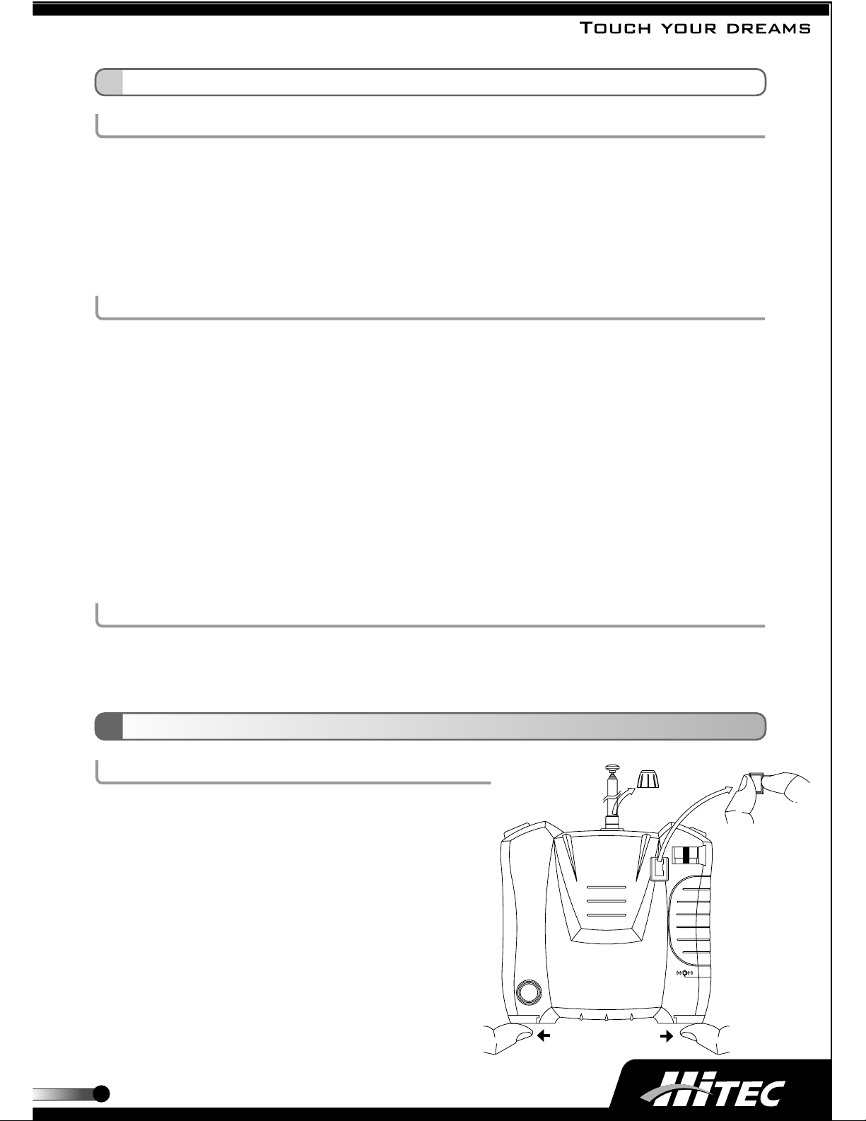
Opening the case
The case of your Neon is unique because it does not have
the traditional screws holding it together.
Instead, we have created a "pull apart" case to facilitate
access to the inside components.
To open your case, unscrew the antenna and remove it,
slide the tabs located at the bottom corners off and gently pull
the bezel at the base of the antenna up, and then remove the
crystal (See Image). Now, separate the two case half's while
being careful of the internal wiring harness to the throttle switch,
unplug the wires leading to the throttle switch, and you can
now access the internal components to add optional feature
packages, reverse your servos, or change the battery out.
OPEN
OPEN
3
Page 4

Reading the LED Battery Indicators
There are three indicator lights on the face of the radio marked High (green), Mid (amber) and Low (red).
These relate to the condition of your transmitter battery. Please pay attention to these LEDs and stop flying when
the red "Low" light is on.
Full Power : Green
HIGH
HIGH
HIGH
MID
LOW
Normal : Amber
MID
LOW
MID
LOW
Warning : Flashing Red
Recharging Nicad batteries
The Deluxe NEON version transmitter is supplied with rechargeable Nicad batteries.
Before using the radio, plug the supplied 110V . CG-25 or 220V. CG-22A overnight wall charger into a normal
household AC wall socket.There are two leads on the CG-25 or CG-22A, the round one plugs into the socket
on the lower left side of the transmitter. The green light on the CG-25 or CG-22A should glow , confirming
charging is taking place; leave it on charge for at least 18 hours. Once fully charged, the transmitter should
operate for about 120 minutes. Typically you will charge the radio up overnight before flying the next day.
Do not leave the radio connected to the wall charger for over 36 hours or permanent damage to the transmitter
battery pack may occur.
CG-25 or CG-22A
#54403 MICRO S/W HARNESS
#54402 AAA size RX Battery box
#57401 RX Nicad (Not included)
Installing T ransmitter Batteries
Hitec offers the NEON in several versions, some complete with rechargeable transmitter batteries and some
"dry" using "alkaline" (non-rechargeable) batteries. Should your system come "dry", consider the option of
adding individual NiCad cells to your battery holder or replacing the battery holder with the optional Hitec
NiCad battery pack, part number 58207. Both packs can be charged with Hitec's overnight wall chargers
as noted above.
T o install or change the batteries in your NEON
Split the case as described in section 4, Set-up and Operation on page 3,
Remove the battery holder.
Install batteries as shown in image.
Reinstall the battery holder.
Note:The NEON transmitter charging circuitry uses a Diode.
This means Hitec cannot recommend the use of "peak" chargers
to charge your NiCad pack within the NEON case.
4
Page 5

T ransmitter antenna
Always have the antenna screwed in securely and fully extended when the transmitter is on,
except when doing a range check.
Elevon/V-tail mix
Your Neon transmitter has a "built-in" channel 1 and 2 mix for flying wing
"elevon" controls and "V-tail" ruddervator controls.
This function is activated with the slide switch on the face of the radio.
There are two factors that determine what direction the servo will
move when the Elevon or V-tail mixing is selected.
- Whether the servo is plugged into the channel 1 or 2 port on the receiver
- The servo "direction of rotation", selectable within the transmitter case.
Using these two functions it is possible to have the two servos move
in the directions required for Elevon or V-tail/Ruddervator control.
If your ailerons and elevator controls are reversed you will need to reverse one or both of the servo reversing
plugs on the main PC board (described below) . If only one of the controls is reversed and you cannot get it set
right with the servo reversing function, you will need to swap the servo leads in the receiver. I.E. plug the servo
in channel #1 into channel #2 and channel #2 into channel #1.
Servo Reversing
After removing the back of the case you will find four plugs
(there are four plugs if you have the optional 4th channel feature).
Simply unplug and rotate the connector 180 degrees, plug it back onto
the board and the servo throw for that servo, is now reversed.
Gimbal stick length adjustment
The gimbal stick is adjustable to suit your personal preference.
Hold the bottom half of the knurled knob and twist the top half
counterclockwise to loosen, adjust the length to your satisfaction
and twist the two pieces to lock them together.
Gimbal stick tension adjustment
The spring tension of the gimbal is also adjustable. Remove the back
of the transmitter case to expose the gimbal mechanism. Note the two
screws associated with the springs. To soften the effect of the springs,
turn the screws counterclockwise, to tighten the "feel" of the gimbal stick,
turn the screws clockwise.
Throttle Function
The Neon 3 features a slide switch located on the back of the transmitter,
it is adjusted with your left index finger as your hand naturally wraps around
the radio case. Use this switch to get proportional control of your throttle
servo, or ESC, (Electronic Speed Control.)
Note: All ESC's connect to your receiver in the channel 3 port.
AB
SERVOREVERSE
NORMAL
G
GYO GYO GYO
YO
CH1 CH2 CH3 CH4
REVERSE
GYO
GYO GYO GYO
CH1 CH2 CH3 CH4
Colors denoteconnector wire colors
Green Yellow Orange
GYO
5
Page 6

ELECTRON 6
ELECTRON 6
5 Installation of Receiver and Servos
HFS-04MGHFS-04MG
Please refer to the aircraft manufacturers instructions on servo , receiver and battery placement within your aircraft.
Channel 1 is Aileron or Rudder / Channel 2 is Elevator / Channel 3 is Throttle / Channel 4 is optional
Deluxe version
ELECTRON 6
-MICRO RECEIVER -DUAL CONVERSION-MICRO RECEIVER -DUAL CONVERSION
FM
Micro Version
X-TAL
HFS-04MG
BATT/CH6
CH5
CH4
CH3
CH2
CH1
#54403 MICRO S/W HARNESS
CH4 : Optional
Throttle Servo
Channel #3
Elevator Servo
Channel #2
Aileron or Rudder Servo
Channel #1
#54402 AAA size RX Battery box
Optional throttle servo or Optional Electronic Speed Control
Turning on your system
Before turning on your transmitter when at a flying field, ask about frequency control. If you turn on your
transmitter when another person is flying on the frequency your radio is on, the other plane will crash and you
will be responsible.
Always turn the transmitter on first, then turn on the receiver. Do the opposite to power down your system, doing this
will avoid damage to your servos and linkages.
Servo trim settings
There are two trim levers on the face of the transmitter
associated with channel 1, the aileron or rudder and
channel 2, elevator. Center these trim lev ers before
installing your servos.These trim levers are used to
make minor trim adjustments while in flight, so the
aircraft can fly straight and level. Do not use these trims to center a flight control surface while the plane is on the
ground or before the first flight, those adjustments should be made with the control linkages before the plane flies.
Range check
Before flying your model, conduct a range check. T urn everything on and collapse the transmitter antenna so
that one section remains exposed. While holding the
-When your plane does this - Move trim like below
transmitter , walk away from the model, you should have full
control over the model without any glitching at least 65 to 75
feet awa y. If your range is less than this, do not fly, as there
would appear to be a problem! Contact the Hitec service
department and we will try to help you.
Checking servo operation
Proper servo linkage geometry is important, all control rods
should be at a 90 degree angle to the servo case.
6
Page 7

6 NEON Transmitter Option Installation Directions.
T rainer P ort and Switch Installation
1. Open the case as instructed on page 3 and disconnect the throttle
switch harness plug from the main board.
2. Disconnect the power from the radio by removing the battery holder
or unplugging and removing the Nicad battery pack.
3. Twist out and remove the plastic cover from the back side of the case
so the trainer plug can be accessed after the case is closed.
Clean up the edges with a hobby knife.
4. Plug the 6 wire plug into the port marked "trainer" and route the
wires so they will not be pinched when the case is re-assembled.
5. Pop the plastic plug out from the top right of the Tx case and
install the switch by removing both small nuts, sliding the switch
Trainer
jack
up through the hole and securing both nuts so the top nut "jams"
the bottom one tight. T aking care to orient the switch so when the Tx is resting in your hand in the flying position,
the switch is pulled towards you and snaps back away from you when released.
6. Route the wires so they will not be pinched when the case is re-assembled.
7. Place the plug port PC board on the four screw posts and use the four screws to secure it.
8. Re-install the battery.
9. Plug the throttle back in.
10. T aking care not to pinch any wires, slide the top of the case half's together then snap the bottom together.
Reinstall the antenna, antenna bezel, crystal and the lower case tabs.
11. All done? Range check your radio and go fly!
Trainer
switch
ATV Board Installation
1. Open the case as instructed on page 3 and disconnect the throttle
switch harness plug from the main board.
2. Disconnect the power from the radio by removing the battery holder
or unplugging and removing the Nicad battery pack.
Screws
3. Remove the four screws holding in the large brown PC board in the
illustration.
4. Without unplugging anything on the board, you should be able to shift
the board up out of the way about 1 inch.
Note: slide the white wire next to the antenna screw post out of the slot.
5. P op the "cover" out from the three small holes and place the ATV board
on the two screw posts. Secure the board with the two supplied screws, be sure to tighten the screws up snug.
6. Taking care to route the wires under the boards as much as possible, re-install the four screws holding down
the large brown PC board.
7. Slide the white wire next to the antenna screw post into the slot and out of the way of the antenna as it is reinserted.
8. Re-install the battery .
9. Plug the throttle back in.
10. Taking care not to pinch any wires, slide the top of the case half's together then snap the bottom together.
Reinstall the antenna, antenna bezel, crystal and the lower case tabs.
11. All done? Range check your radio and go fly!
7
Page 8

Dual Rate Switch Installation
Note: ATV board component must be installed prior to adding the
Dual Rate Switch.
1. Open the case as instructed on page 3 and disconnect the throttle
switch harness plug from the main board.
2. Disconnect the power from the radio by removing the battery holder or
Dual rate switch
unplugging and removing the Nicad battery pack.
3. Remove the four screws on the front of the radio that hold the gimbal in.
4. Remove the plug in the hole marked, D/R
5. Slide the Dual Rate Switch into the hole and secure with the lock nut.
6. Reinstall the gimbal.
7. Route the wire and attach the white connector into the plug marked
DR S/W on the large brown PC board.
8. Re-install the battery .
9. Plug the throttle back in.
10. Taking care not to pinch any wires, slide the top of the case half's together then snap the bottom together.
Reinstall the antenna, antenna bezel, crystal and the lower case tabs.
11. All done? Range check your radio and go fly!
4th Channel Three Position Switch Accessory Installation
1. Open the case as instructed on page 3 and disconnect the throttle
switch harness plug from the main board.
2. Disconnect the power from the radio by removing the battery holder
or unplugging and removing the Nicad battery pack.
3. Remove the plug in the hole marked, AUX.
4. Slide the Switch into the hole and secure with the lock nut.
5. Route the wire and attach the connector into the plug marked CH-4
G
CH1 CH2 CH3 CH4
CH1 CH2 CH3 CH4
SERVO REVERSE
NORMAL
GYO GYO GYO
YO
REVERSE
GYO
GYO GYO GYO
Colors denote connector wire colors
Green Yellow Orange
GYO
on the large brown PC board.
6. Re-install the battery .
7. Plug the throttle back in.
8. Taking care not to pinch any wires, slide the top of the case half's together then snap the bottom together.
Reinstall the antenna, antenna bezel, crystal and the lower case tabs.
9. All done? Range check your radio and go fly!
Austria, Belgium, Denmark, Finland,
France, Germany, Greece, Iceland,
Ireland, The Netherland, Italy, Spain,
Norway, Portugal, United Kingdom,
Luxembourg, Sweden, Switzerland
NEON-SS FM
optional version
www.hitecrcd.com
 Loading...