

Page 1
Page 2

INTRODUCTION
LAYOUT DIAGRAM
FEATURES AND SPECS
SETTING AND OPERATION
1. Transmitter
■ Loading batteries
■ Reading the LED battery indicators
■ Recharging NiCad batteries
■ Transmitter antenna
■ Changing x-tals
2. Installation of Receiver and Servos
CONTENTS
■ Using separate power source for the receiver
■ Battery Eliminator Circuitry (B.E.C.) with mechanical speed controls
■ Connection with electronic speed control.
3. Transmitter, Receiver and Servo Settings
■ Checking operation of the servo
■ Steering Servo Settings
■ Steering Rate Override switch (S.R.O.)
■ Steering Rate Adjustment (S.R.A.)
■ Steering servo trim setting
■ Throttle Servo Settings
■ Using mechanical speed control
■ Using electronic speed control
■ Using throttle servo for gas powered vehicles
■ Setting End Point Adjustment (E.P.A.)
1
Page 3
23456789012345678901234567890121234567890123456789012345678901212345678901234567890123456
7
7
7
7
7
23456789012345678901234567890121234567890123456789012345678901212345678901234567890123456
INTRINTR
INTR
INTRINTR
ODUCTIONODUCTION
ODUCTION
ODUCTIONODUCTION
Thank you for purchasing the LYNX 2 Channel FM Radio System. The LYNX 2 FM Radio is
made of high quality, technically advanced components designed to achieve top performance
from you RC Vehicle. Team up with Hitec Racing and see that quality and performance doesn’t
have to cost a fortune!
23456789012345678901234567890121234567890123456789012345678901212345678901234567890123456
23456789012345678901234567890121234567890123456789012345678901212345678901234567890123456
23456789012345678901234567890121234567890123456789012345678901212345678901234567890123456
LALA
YY
LA
LALA
Y
YY
OUT DIAOUT DIA
OUT DIA
OUT DIAOUT DIA
GRAMGRAM
GRAM
GRAMGRAM
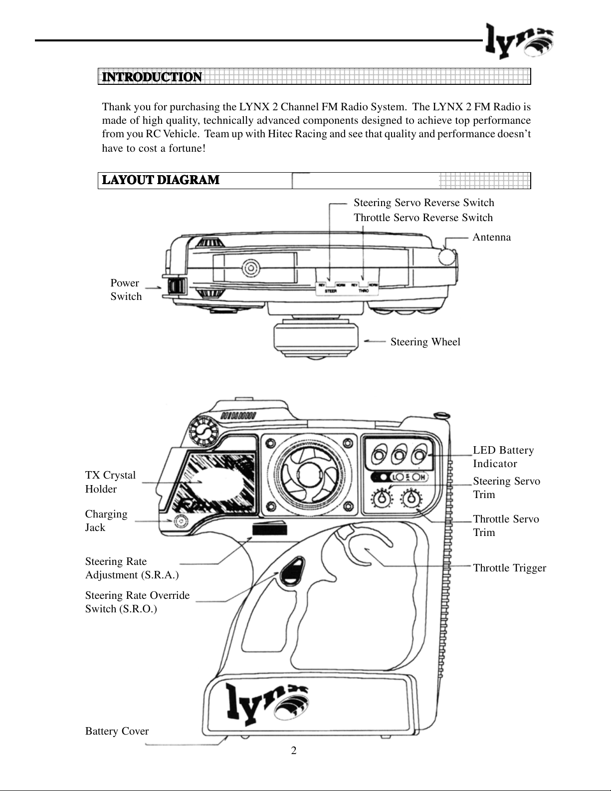
Steering Servo Reverse Switch
Throttle Servo Reverse Switch
Antenna
Power
Switch
Steering Wheel
TX Crystal
Holder
Charging
Jack
Steering Rate
Adjustment (S.R.A.)
Steering Rate Override
Switch (S.R.O.)
Battery Cover
LED Battery
Indicator
Steering Servo
Trim
Throttle Servo
Trim
Throttle Trigger
2
Page 4
23456789012345678901234567890121234567890123456789012345678901212345678901234567890123456
7
7
7
7
7
23456789012345678901234567890121234567890123456789012345678901212345678901234567890123456
23456789012345678901234567890121234567890123456789012345678901212345678901234567890123456
FEAFEA
FEA
FEAFEA
TURESTURES
TURES
TURESTURES
AND SPECSAND SPECS
AND SPECS
AND SPECSAND SPECS
Pistol Grip 2 Channel FM Proportional System
Servo Reversing Switches (Both Channels)
Steering Rate Adjustment. Thumb Controlled (40% - 100%)
Adjustable Steering Rate Override button (40% - 100%)
End Point adjustment (E.P.A.) Throttle and Brake
3 LED Battery Status Indicators
Power Output: 500mW
Current Drain: 180mA
23456789012345678901234567890121234567890123456789012345678901212345678901234567890123456
23456789012345678901234567890121234567890123456789012345678901212345678901234567890123456
SETTINGSSETTINGS
SETTINGS
SETTINGSSETTINGS
AND OPERAAND OPERA
AND OPERA
AND OPERAAND OPERA
TIONTION
TION
TIONTION
1. TRANSMITTER
Loading batteries:Loading batteries:
■
Loading batteries:
Loading batteries:Loading batteries:
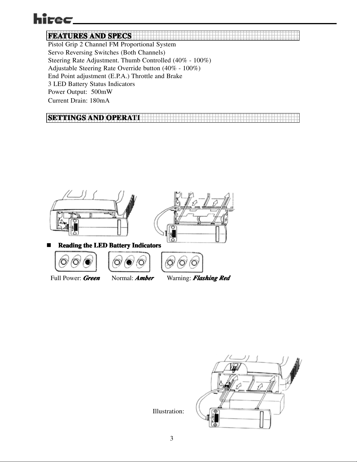
You may us either NiCad batteries or Alkaline “AA” size batteries (NiCad recommended)
✷ Push the bottom battery cover in the direction of the arrow then lift up the cover.
✷ Load 8 “AA” batteries (be sure the polarity is correct).
✷ Reinstall battery case with installed “AA” batteries with connections to the top left.
✷ NiCads should be charge before use.
Reading the LED Battery IndicatorsReading the LED Battery Indicators
Reading the LED Battery Indicators
Reading the LED Battery IndicatorsReading the LED Battery Indicators
GrGr
eeneen
Gr
een
Full Power:
GrGr
eeneen
Normal:
With new alkaline or freshly charged NiCads the
AmberAmber
light will turn to
Amber
AmberAmber
. If the
AmberAmber
Amber
AmberAmber
Warning:
RedRed
Red
light begins to flash, operation should be stopped and the
RedRed
Flashing RedFlashing Red
Flashing Red
Flashing RedFlashing Red
GrGr
eeneen
Gr
een
light should be lit. With use the
GrGr
eeneen
batteries should be recharged or replaced immediately.
■ Optional NiCad Battery Installation (part # 58207).
1. Plug the white battery plug into the receptacle in the bottom of the pistol grip handle.
(Refer to Illustration)
2. Push the pack up into the battery bay.
3. Replace the cover.
4. Check the power level.
5. Charge if needed. (Refer to illustration below)
Illustration:
GrGr
Gr
GrGr
eeneen
een
eeneen
3
Page 5

■ ■
■ Recharging NiCad Batteries
■ ■
The LYNX is equipped with an external charging jack so there is no need to remove the
battery pack from the transmitter. The Hitec CG-22 or 25A are made to charge these types
of batteries overnight or the approximately 12-15 hours. Please refer to the following
diagram, check to see that the charge light lights up after the connection is complete.
CG-22 or CG-25A
#7201 Battery
Holder
#7401 RX NiCad
Battery
■ ■
■ Transmitter Antenna
■ ■
You must attach the transmitter antenna by screwing it into the hole located at the top left/
center of the transmitter. You may take the antenna out to store it. This storage area is
located on the backside of the transmitter. Always attach your antenna before use or you
will experience sever shortage of operating range that could result in damage to your vehicle
and or injuries to yourself and others.
4
Page 6

■ ■
■ Changing X-tals
■ ■
Changing the x-tal to void conflicts with other vehicles is possible where permitted. (You must
check your local rules before doing so. For example, in the US, the FCC prohibits the changing
of transmitter x-tals on 72 and 75MHz). If you are eligible to change the x-tals, both the
transmitter and receiver x-tals must be changed together. You must change within the same
band, i.e. 75MHz to 75MHz, 27MHz to 27MHz, different bands can not be intermixed if your
radio is on 75MHz then 27MHz x-tals cannot be used. Use only Hitec x-tals when changing
frequencies.
Rx Crystal
Tx Crystal
2. Installation of Receiver and Servos
■ ■
■ Using separate power source for the receiver
■ ■
When using a separate power pack for the receiver instead of sharing the main power source,
please refer to the following diagram. After installation, turn on the power to the transmitter
first then turn the receiver on. (Always turn the transmitter ON first and OFF last.) This will
prevent the receiver from picking up stray signals and going out of control. Now, move the
controls to see if the servos are moving properly. If not, Check your wiring, battery charge or xtals if the servos do not move at all.
Throttle
Servo
Steering
Servo
■ ■
■ Battery Eliminator Circuitry (B.E.C.) Included in AM Model Only.
■ ■
5
Page 7

■ ■
Connection with ElectrConnection with Electr
■
Connection with Electr
■ ■
Connection with ElectrConnection with Electr
onic Speed Contronic Speed Contr
onic Speed Contr
onic Speed Contronic Speed Contr
olol
ol
olol
Electronic Speed Controls such as the Hitec HFX have a built in B.E.C. system inside the
speed control circuit. (Please verify whether your ESC has a built in B.E.C. circuit.) Plug
the receiver connector from the speed control into the “THROTTLE” or #2 channel on the
receiver, and the steering servo into the “STEERING” or #1 channel on the receiver. Now
you can connect the main power to the speed control and when the power switch is turned
on the speed control will regulate the power that the receivers can use.
Motor
Electronic Speed
Control
Main Power Pack
Steering
Servo
3.T3.T
rr
3.T
3.T3.T
r
rr
ansmitteransmitter
ansmitter
ansmitteransmitter
,,
Recei Recei
,
Recei
,,
Recei Recei
vv
er and Serer and Ser
v
er and Ser
vv
er and Serer and Ser
vv
o Settingso Settings
v
o Settings
vv
o Settingso Settings
Now we come to the critical part, as proper installation of these three main components
is essential.
■ ■
ChecChec
■
■ ■
king operking oper
Chec
king oper
ChecChec
king operking oper
✷ After the installing of the servo and receiver into your model, turn the transmitter
aa
tion of the sertion of the ser
a
tion of the ser
aa
tion of the sertion of the ser
vv
oo
v
o
vv
oo
power “ON” and fully extend the antenna, now turn on the receiver. (It is advisable to
remove the pinion gear from your car so that the wheels do not engage for this test).
✷ Check to see if either servos or speed control are working properly. If not check the
connections and make sure the main battery pack is charged.
6
Page 8

✷
Check to see if the servos are moving in the correct direction. If not, change the
position of the servo-reversing switch located on the top of the transmitter to achieve
the correct direction.
✷ If everything checks out then turn the receiver “OFF” first then the transmitter. (Always
remember; never have the receiver “ON” without the transmitter also being “ON”).
WW
arar
ning!!!:ning!!!:
W
ar
ning!!!:
WW
arar
ning!!!:ning!!!:
ee
xcess wirxcess wir
e
xcess wir
ee
xcess wirxcess wir
yy
ourour
self and otherself and other
y
our
self and other
yy
ourour
self and otherself and other
Do not shor Do not shor
Do not shor
Do not shor Do not shor
ee
..
TT
his will sehis will se
e
.
T
his will se
ee
..
TT
his will sehis will se
s.s.
s.
s.s.
ten the length of the rten the length of the r
ten the length of the r
ten the length of the rten the length of the r
vv
erer
elel
y afy af
ff
v
er
el
vv
erer
elel
ect the operect the oper
y af
f
ect the oper
y afy af
ff
ect the operect the oper
aa
ting rting r
a
ting r
aa
ting rting r
eceiecei
vv
er antenna ber antenna b
ecei
v
er antenna b
eceiecei
vv
er antenna ber antenna b
angang
e and could re and could r
ang
e and could r
angang
e and could re and could r
y cutting ofy cutting of
y cutting of
y cutting ofy cutting of
esult in injuresult in injur
esult in injur
esult in injuresult in injur
f anf an
f an
f anf an
y toy to
y to
y toy to
yy
y
yy
No
■ ■
SteerSteer
Steer
SteerSteer
ing Raing Ra
ing Ra
ing Raing Ra
ing Sering Ser
ing Ser
ing Sering Ser
■
■ ■
-Steer-Steer
-Steer
-Steer-Steer
The most notable feature in the LYNX is the “Steering Rate Override (SRO) Switch”.
This feature allows you to override the dual rate and use from 40% - 100% steering travel
with one touch. Selectable via the screw adjustment on the face of the transmitter, this can
be used in situations where your dual rates are set so the car does not “Oversteer” on the
majority of the track but is set low to get around the hairpin. By pushing the “SRO” switch
as you approach the hairpin turn, you will get the preprogram amount of throw immediately
and be able to get around the turn faster. If you are stuck against the hose/board/wall/etc.
and don’t have enough steering throw to get you out, the “SRO” button on the LYNX can
get you out when other radios can’t. Experiment with this feature you will find it very
beneficial.
vv
o Settingso Settings
v
o Settings
vv
o Settingso Settings
te Ovte Ov
te Ov
te Ovte Ov
erer
rr
ide Switcide Switc
er
r
ide Switc
erer
rr
ide Switcide Switc
h (Sh (S
h (S
h (Sh (S
.R.O.R.O
.R.O
.R.O.R.O
.).)
.)
.).)
7
No Yes
Page 9

- Steer- Steer
- Steer
- Steer- Steer
ing Raing Ra
ing Ra
ing Raing Ra
tete
Adjustment (SAdjustment (S
te
Adjustment (S
tete
Adjustment (SAdjustment (S
.R.A.).R.A.)
.R.A.)
.R.A.).R.A.)
Dual rates for the steering servo can adjusted via the thumbscrew on the pistol grip. This
adjustment is critical for racers fine-tuning their cars handling “On the Fly”. The rate can
be selected from 40% - 100%. If your car is loose or “Oversteering”, dial the adjustment
back. If your car is pushing or “Understeering”, then dial the adjustment forward. This
adjustment is a must for setting up your car to perform at its best. Adjust the servo so at
100% of travel (the dial will be all the way forward), the servo does not bind. If the servo
binds, adjust the linkage to compensate. (Consult your vehicle’s instruction manual for
proper instructions on the linkage setup)
A
B
40% 100%
A: Normal
B: Steering Rate Override Switch “ON”
Max. 100%
Min. 40%
- Steer- Steer
- Steer
- Steer- Steer
ing Sering Ser
ing Ser
ing Sering Ser
vv
oo
TT
rr
o
T
vv
oo
TT
im Settingim Setting
r
im Setting
rr
im Settingim Setting
v
After verifying that the steering direction is correct, set the knob to the center. The servo
horn or arm should be a 90 degrees and the wheels should be straight. If not then make the
horn or arm 90 degrees by removing it and replacing it correctly. If the arm is at 90
degrees and the wheels are not straight, adjust the linkage to compensate. Once you have
these two settings correct, use the steering trim for fine-tuning. Note: Always trim your
car before you run or race. This is a common mistake made by beginners. If you have to
steer your car to go straight, you are fighting a loosing battle. Make sure it tracks straight
before you run it and driving will become much easier.
8
Page 10

Fine Tuning
Tilting Left Tilting Right
Steering
Trim
• •
TT
hrhr
ottle Serottle Ser
•
T
hr
ottle Ser
• •
TT
hrhr
ottle Serottle Ser
Using Mec Using Mec
Using Mec
Using Mec Using Mec
Tilting Left
Trimming
Throttle
Trim
vv
o Settingso Settings
v
o Settings
vv
o Settingso Settings
hanical Speed Contrhanical Speed Contr
hanical Speed Contr
hanical Speed Contrhanical Speed Contr
A
A
AB
Steer
olol
ol
olol
C
B
Tilting Right
Trimming
Steer
B
C
B
A
Adjust the servo link rod so that point “B” will arrive at the neutral position. When the
trigger is pulled to the maximum point, “C” should be as illustrated and at point “A” when
the trigger is pushed to the limit. Check to see if the vehicle moves forward when the
trigger is pulled. If the vehicle moves backwards the “Throttle” reversing switch will need
to be switched. If the model moves forward or reverse at the neutral position, use the
throttle servo trim to fine tune. If the servo moves the speed control farther than is needed
use the “EPA” adjustments to limit the travel to the proper distance.
- Using a Electr- Using a Electr
- Using a Electr
- Using a Electr- Using a Electr
✷ Set the throttle trim in the center then adjust the ESC neutral point. Use the trim for
onic Speed Contronic Speed Contr
onic Speed Contr
onic Speed Contronic Speed Contr
olol
ol
olol
fine-tuning adjustments.
Hint:Hint:
Set a little dr Set a little dr
Hint:
Set a little dr
Hint:Hint:
Set a little dr Set a little dr
drdr
aa
g brg br
dr
drdr
car will crcar will cr
car will cr
car will crcar will cr
ff
orworw
f
orw
ff
orworw
ff
orworw
f
orw
ff
orworw
to alloto allo
to allo
to alloto allo
akak
a
g br
ak
aa
g brg br
akak
arar
d to kd to k
ar
d to k
arar
d to kd to k
arar
d onld onl
ar
d onl
arar
d onld onl
w them to carw them to car
w them to car
w them to carw them to car
e or a little e or a little
e or a little
e or a little e or a little
aa
wl fwl f
a
wl f
aa
wl fwl f
y ESCs).y ESCs).
y ESCs).
y ESCs).y ESCs).
aa
g brg br
a
g br
aa
g brg br
“cr“cr
“cr
“cr“cr
orworw
arar
orw
orworw
eeee
p the car frp the car fr
ee
p the car fr
eeee
p the car frp the car fr
d wd w
ar
d w
arar
d wd w
TT
T
TT
rr
y mory mor
r
y mor
rr
y mory mor
akak
e in care in car
ak
e in car
akak
e in care in car
eeee
p”p”
ee
p”
eeee
p”p”
hen the thrhen the thr
hen the thr
hen the thrhen the thr
om moom mo
om mo
om moom mo
his fhis f
eaea
his f
ea
his fhis f
eaea
e speed into and thre speed into and thr
e speed into and thr
e speed into and thre speed into and thr
s thas tha
s tha
s thas tha
f f
or caror car
f
or car
f f
or caror car
ving wving w
ving w
ving wving w
turtur
e is used with 4-we is used with 4-w
tur
e is used with 4-w
turtur
e is used with 4-we is used with 4-w
t art ar
e Undere Under
t ar
e Under
t art ar
e Undere Under
s thas tha
t ot o
s tha
s thas tha
ottle is in neutrottle is in neutr
ottle is in neutr
ottle is in neutrottle is in neutr
vv
t o
v
t ot o
vv
hen stoppedhen stopped
hen stopped
hen stoppedhen stopped
steersteer
steer
steersteer
erer
steer into the corsteer into the cor
er
steer into the cor
erer
steer into the corsteer into the cor
heel drheel dr
heel dr
heel drheel dr
ough the corough the cor
ough the cor
ough the corough the cor
ing into the coring into the cor
ing into the cor
ing into the coring into the cor
al,al,
so y so y
al,
al,al,
. (T. (T
. (T
. (T. (T
ou mou m
so y
ou m
so y so y
ou mou m
his can onlhis can onl
his can onl
his can onlhis can onl
ii
vv
e sedan care sedan car
i
v
e sedan car
ii
vv
e sedan care sedan car
nerner
ner
nerner
.
nerner
s and set nos and set no
ner
s and set no
nerner
s and set nos and set no
nerner
s.s.
TT
ner
nerner
ust push the trust push the tr
ust push the tr
ust push the trust push the tr
..
..
his means thehis means the
s.
T
his means the
s.s.
TT
his means thehis means the
y be done withy be done with
y be done with
y be done withy be done with
s quite frs quite fr
s quite fr
s quite frs quite fr
igig
gg
ig
g
igig
gg
equentlequentl
equentl
equentlequentl
erer
er
erer
yy
y
yy
9
Page 11

* Set the thr* Set the thr
* Set the thr
* Set the thr* Set the thr
✷
Adjust the full power position of the ESC (forward only) when the trigger is pulled
ottle trottle tr
ottle tr
ottle trottle tr
im in the centerim in the center
im in the center Adjust Neutral Point
im in the centerim in the center
approximately 90% of the way. If the vehicle does not move forward when the trigger
is pulled and does when the trigger is pushed, check the motor connection first. If that
is correct then switch the throttle reversing switch to the opposite direction.
✷ Adjusting the full power position of the ESC (reversible version) is the same as the
forward only, except you must make sure you are adjusting the forward not the reverse.
If the trigger is pulled and the full power adjustment does not affect the speed but does
when the trigger is pushed, the servo reversing switch for the throttle needs to be changed
to the opposite direction. After this is determined, use the same 90% as discussed
previously for forward. Reverse on most speed controls is not adjustable.
Brake or Reverse
Throttle Trigger
Neutral Position
- Using thr- Using thr
- Using thr
- Using thr- Using thr
ottle serottle ser
ottle ser
ottle serottle ser
90%
Full Forward
vv
o fo f
or gor g
v
o f
or g
vv
o fo f
or gor g
as poas po
as po
as poas po
ww
w
ww
erer
er
erer
ed ved v
ed v
ed ved v
ehicehic
ehic
ehicehic
lele
le
lele
Adjust Full Power Position
Gas powered vehicles require the throttle servo to be set up to operate the carburetor and
brakes together. The EPAs are used in these cars to set the proper throw for the throttle
and brakes. Setups are different for individual applications so consult the manufactures
manual for the proper setup procedure.
- Using thr- Using thr
- Using thr
- Using thr- Using thr
ottle End Pottle End P
ottle End P
ottle End Pottle End P
ointoint
Adjustments (E.PAdjustments (E.P
oint
Adjustments (E.P
ointoint
Adjustments (E.PAdjustments (E.P
.A.).A.)
.A.)
.A.).A.)
Throttle (EPA) can be used in conjunction with electronic and mechanical speed controls
as well as gas powered cars. Use the EPA to select the proper amount of travel for the
throttle and brake.
FCC INFORMAFCC INFORMA
FCC INFORMA
FCC INFORMAFCC INFORMA
TRANSMITTER FREQUENCIES CAN ONLY BE CHANGED BY AN AUTHORIZED HITEC RCD SERVICE CENTER. CHANGING
FREQUENCIES BY THE CONSUMER WILL VOID THE WARRANTY AND IS A VIOLATION OF FCC REGULATIONS.
TIONTION
TION
TIONTION
10
Page 12

FM
PISTOL TYPE 2 CHANNEL AM RADIO
CONTROL SYSTEM
 Loading...