

Page 1

OPERATION MANUAL
Page 2

MANUAL: SECTION 1
Table of Contents
Section 1: Introduction
Introduction.................................................................................................................................................................................04
Safety Precaution........................................................................................................................................................................04
Lynx 4S Layout.............................................................................................................................................................................06
Changing the Position of the Steering Wheel........................................................................................................................11
Modifying for Left-Hand Users................................................................................................................................................13
Rubber Grip and Neck Strap...................................................................................................................................................13
Receiver.........................................................................................................................................................................................14
Receiver Installation...................................................................................................................................................................16
Receiver Connection Diagrams...............................................................................................................................................17
Charging........................................................................................................................................................................................17
Main Display..................................................................................................................................................................................19
Sub Menus.....................................................................................................................................................................................20
Section 2: Model Programming
R.E.V (Servo Reverse).................................................................................................................................................................21
E.P.A (End Point Adjust)..............................................................................................................................................................21
A.T.L (Brake Rate)......................................................................................................................................................................22
A.B.S (Anti-Lock Brake)............................................................................................................................................................22
ST-EXP (Steering Exponential)..................................................................................................................................................23
BK-EXP (Brake Exponential).....................................................................................................................................................24
TH-EXP (Throttle Exponential)...............................................................................................................................................24
ST-D/R (Steering Dual Rate).....................................................................................................................................................25
S-TRIM (Sub Trim).......................................................................................................................................................................25
Fail-Safe..........................................................................................................................................................................................26
BOOST (Auto Boost)................................................................................................................................................................27
ST-SPD (Sterring Servo Speed).................................................................................................................................................27
TH-SPD (Throttle Servo Speed)..............................................................................................................................................28
TH-MOD (Throttle Mode).......................................................................................................................................................28
IDL-UP (Idle Up/Down).............................................................................................................................................................29
Timer (Race Timer).....................................................................................................................................................................29
Countdown Timer.......................................................................................................................................................................30
Lap Timer........................................................................................................................................................................................31
Lap List (Lap Time Listings)........................................................................................................................................................31
Switch (Switch Functions, Assignments & Settings).............................................................................................................32
Assignable Switch List.................................................................................................................................................................33
Function of Switch.......................................................................................................................................................................34
Dial (Radio Dial Functions & Settings)....................................................................................................................................35
Dial Function................................................................................................................................................................................36
Mix (Channel Mixing)..................................................................................................................................................................37
Type of Mixing...............................................................................................................................................................................37
4WS (4 Wheel Steering).............................................................................................................................................................38
Crawler...........................................................................................................................................................................................38
P2
Page 3

MANUAL: SECTION 1
Table of Contents
Section 3: System Programming
ST-ADJ (Steering Adjustments)................................................................................................................................................39
TH-ADJ (Throttle Adjustments).............................................................................................................................................39
RX-Bind (Receiver Binding)......................................................................................................................................................40
RF-Scan (Radio Frequency Scanning).......................................................................................................................................41
Servo (Servo Monitoring)........................................................................................................................................................42
Sensor (Telemetry Sensor Setup)...........................................................................................................................................42
Management (Radio System Management Settings)............................................................................................................47
Telemetry (Telemetry Display)................................................................................................................................................48
Vibration.......................................................................................................................................................................................49
Battery (Battery Type Settings)................................................................................................................................................49
Section 4: Model Management
Name (Model Naming)............................................................................................................................................................50
Delete (Model Delete)............................................................................................................................................................50
Copy (Model Copy)....................................................................................................................................................................51
Change (Active Model Selection)...........................................................................................................................................51
Section 5: SD Card Management
SD-Name (SD Card Model Naming))....................................................................................................................................52
SD-Delete (SD Card Model Delete)......................................................................................................................................52
SD-Import (SD Card Model Import).....................................................................................................................................53
SD-Export (SD Card Model Export).....................................................................................................................................53
Voice (Voice Function)...............................................................................................................................................................54
Music (Music Play)........................................................................................................................................................................54
Warning & Error Messages.......................................................................................................................................................55
P3
Page 4

MANUAL: SECTION 1
Introduction
Thank you for purchasing the Lynx 4S Radio by Hitec!
As Hitec’s latest contribution in outstanding surface radio technology, the four-channel Lynx 4S is equipped
with lightning fast 4ms response, 4096 resolution, and Hitec’s unique bi-directional, AFHSS (Advanced Frequency Hopping Spread Spectrum) function for use with all popular R/C-operated models. Feature-packed with
an easy-to-use interface, the Lynx 4S design promises a more enjoyable and safer R/C experience than ever
before.
Prior to using your Lynx 4S 2.4GHz system, it is highly recommended that you read this manual carefully and in
full to ensure operation of the unit as intended. It’s also a good idea to keep these instructions with your Lynx
4S for easy reference at all times.
Please note that Hitec reserves the right to make production changes during the life of our product lines
which may impact the information in this manual.
For the most up-to-date information on this and any other Hitec product, visit our web site at www hitecrcd.com.
Safety Precaution
Flying models can be dangerous if proper safety precautions are not followed as described. Here are a few critical safety suggestions to keep you and others safe.
Do not operate the Lynx 4S during inclement weather.
Do not operate under conditions of poor visibility.
Do not operate your model in close proximity to others wherever their presence could result in personal
injury or property damage.
Do not operate R/C boats where passenger boats are present or where swimmers, bathers, or others participating in water activity may be in danger.
Please note that Radio Control Systems are susceptible to interference when high tension power lines, power
transmission towers, or power transmission sites are near.
Minors under 19 years of age are encouraged to operate their model under adult supervision.
We strongly recommend that anyone new to R/C solicit guidance from seasoned users or their local R/C shop.
Do not store your R/C system in places exposed to extreme heat (over 40°) or cold (below 10°), or where it
can be compromised by direct sunlight, dust, or jarring.
Prior to activating your model, always check your Lynx 4S for a normal response. Double check that your settings are as desired and that your radio is functioning as it should.
P4
Page 5

MANUAL: SECTION 1
Safety Precaution (cont.)
Always check the transmitter’s throttle trigger to be sure it rests in a neutral position before powering “ON”
your system. Make sure your model’s engine is not running when powering down.
Always turn the transmitter power switch on rst before turning on either the receiver or speed control. Reverse the order when powering down: be sure to turn off the receiver and speed control rst, then power off
your transmitter.
Always set up the fail safe function. The fail safe function is a safety feature that minimizes damage by moving
the servos to a preset position when reception fails.
When the Lynx 4S is not being used, always remove or disconnect the battery to prevent personal injury or
property damage.
Do not drop the battery or subject it to jarring vibrations or extreme temperatures.
Do not leave the radio system or models within the reach of small children.
Leakage from the battery may potentially result in skin burn, loss of sight, and other injures. If exposed, thoroughly rinse the affected area and contact your doctor for proper treatment response.
Use approved transmitters, receivers, servos, ESCs (electronic speed controls), Ni-MH/Ni-CD batteries and
other optional accessories ONLY. Hitec is not responsible for issues that arise from the use or misuse of
equipment not specied in this instruction manual or our catalog.
Always exercise proper care in the use and storage of your Hitec product. Exposure to vibration, dust, or extreme temperatures may affect its functionality and your safety.
P5
Page 6
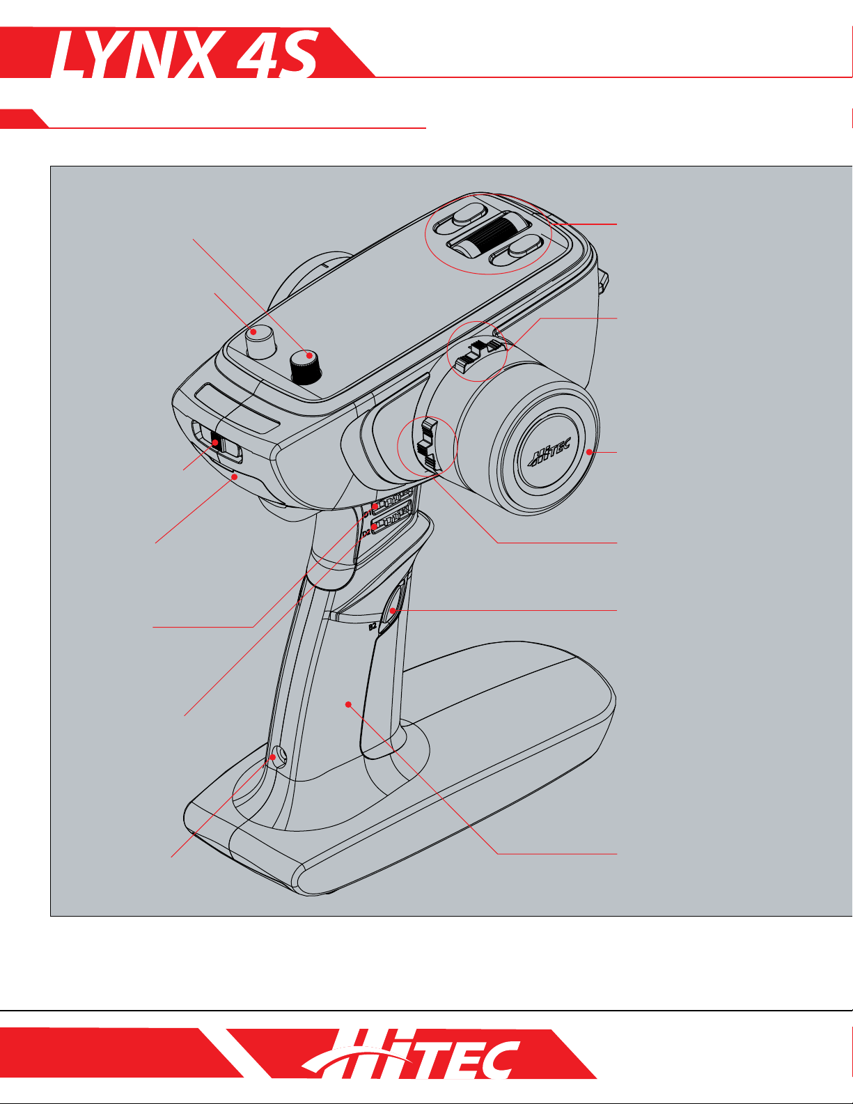
LYNX 4S Layout
MANUAL: SECTION 1
M. Dial /Push Button D3
L. Push /Lock Button B1
K. Power Switch /
Display
J. Protection Cover
(Earphones Port, PC Port)
C. Dial D1
(Steering Dual Rate)
A. Programming Button
(Main Dial, ESC)
B. Digital Trim T1
(Steering Trim)
F. Steering Wheel
B. Digital Trim T2
(Steering Trim)
G. Digital Button B2
(4CH : AUX 2)
C. Dial D2
(Actual Travel Length)
I. Charging Port
The Switch, Dial, and Digital Trim output on the diagram may differ slightly from those of your own radio. The default settings are
pictured above.
H. Grip Handle
P6
Page 7
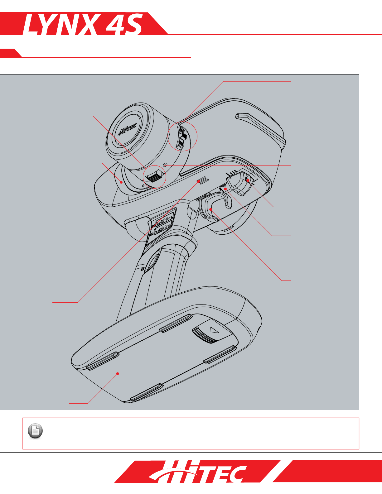
LYNX 4S Layout
Note
P. 3-Position Slide Switch
MANUAL: SECTION 1
B. Digital Trim T3
O. LED Lamp
Q. Speaker
D. Steering Tension
Adjustment
E. Brake Limiter
S. Throttle Tension
Adjustment
R. Throttle Trigger
N. Battery Cover
Should you change the function set-up for the Digital Button, Digital Trim, or Dial, turn off the power switch ONLY
AFTER waiting several seconds. Powering down too quickly may result in your changes being lost.
P7
Page 8
MANUAL: SECTION 1
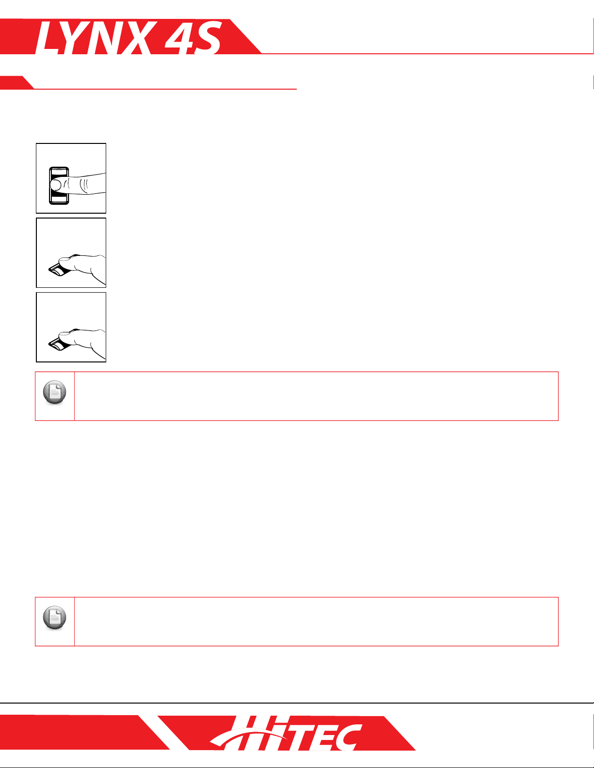
[Scroll] [Short Click] [Long Click]
Note
Note
LYNX 4S Layout (cont.)
A. Programming Buttons:
Main Dial: Use the main dial to scroll through menu options or to change the value of programmable functions.
Scroll:
Move through all function and display menus. When a function with user-specied values
(TEMP, VOLT, SPEED, etc.) is highlighted, use the scroll feature of the Main Dial to view the
range of possible values for that function.
Short Click:
Select the menu or set value.
Long Click:
Revert to the original default set value by holding down the Main Dial for a one second count.
Adjust the servo horn or use the S-TRIM set-up feature if your R/C model fails to drive in a straight line even after
programming the trim to its max setting.
C. Dial D1 / D2:
Through the fast dial control of the Lynx 4S, you can adjust set-up values quickly for 22 different functions. For
more details, please refer to Page 38.
D. Steering Tension Adjustment:
For the convenience of the user, you can adjust the steering tension on your Lynx 4S steering wheel to your
preference with the use of a 1. 5mm hex wrench. To stiffen the resistance of the steering wheel, turn the
wrench clockwise. To make the tension of the steering wheel smoother, turn the wrench counterclockwise.
E. Brake Limiter:
For the convenience of the user, you can adjust the brake’s maximum travel range to your preference with the
use of a 2.5mm hex wrench. To shorten the brake’s travel range, turn your wrench clockwise. To lengthen the
brake’s travel range, turn your wrench counterclockwise.
Please review and adjust as necessary the set-up values for neutral servo position, throttle, EPA, EXP and so on
whenever you alter the brake’s travel range.
F. Steering Wheel:
Control the direction of the model.
P8
Page 9
MANUAL: SECTION 1
Note
Note
Note
LYNX 4S Layout
G. Digital Button B2:
Through the push/lock-style Digital Button, you can initiate or close 18 different Lynx 4S menu screens.
For more details, please refer to Page 35.
H. Grip Handle:
The ergonomic design of the Lynx 4S grip handle allows you to comfortably and condently maintain stable
control of your R/C model.
I. Charging Port:
Requires the use of Hitec’s Lynx 4S overnight charger via the radio’s own built-in charging port.
Please note that other non-Hitec chargers are neither tested nor approved for compatibility with your Lynx 4S.
Depending on the country of purchase, some versions of the Lynx 4S radio system do not include overnight chargers.
J. Protection Cover (earphone port, PC port):
Connecting your earphones or headphones to the Lynx 4S enhances the user experience by adding an audio
component with telemetry voice data or music. By connecting the Lynx 4S to your PC with an HPP-22 add-on
option, you can update the rmware of your Lynx 4S as it becomes available.
Depending on the country of purchase, some versions of the Lynx 4S radio system do not include overnight chargers.
K. Power Switch / Display:
With a 3-position switch, the user navigates through PWR ON, OFF, and DISP ON positions as desired.
To turn on the transmitter and RF module together, move the power switch to the right. Moving the power
switch to the left position activates the display menu only, without the RF module.
Please power “ON” your transmitter before your receiver and power “OFF” your receiver before the transmitter to
avoid accident or unintended consequences.
L. Push/Lock Button B1:
Through the push/lock- style Digital Button, you can initiate or pause 9 different menus on your Lynx 4S. For
more details, please refer to Page 35.
M. Dial & Push Button D3:
With a combined dial /push button, you can control each dial and push input separately.
The D3 dial button allows for the adjustment of 22 different Lynx 4S set-up values. The D3 push button
controls the set-up values for 18 different Lynx 4S functions. For more details, please refer to Page 35.
N. Battery Cover:
The battery cover offers outer protection from shock vibrations and dust particles. Please ensure that the
cover is on securely any time you replace the battery.
P9
Page 10
MANUAL: SECTION 1
Note
LYNX 4S Layout cont.
O. LED Lamp:
The LED Lamp has a lighting scheme of six different colors that indicate a corresponding status of your Lynx 4S.
P. 3-Position Slide Switch SW1:
With a 3-Position switch, you can adjust the set-up value for 4 different Lynx 4S functions.
This switch is especially useful for Crawler models or those models with individual wheel control.
Q. Speaker:
The built-in speaker emits telemetry voice data and music audio.
R. Throttle Trigger:
The throttle trigger determines forward and reverse acceleration as well as brake control.
S. Throttle Tension Adjustment:
Users are able to adjust throttle tension with a 1.5 mm hex wrench. To create stiffer tension in the
throttle, insert and turn the wrench clockwise. To create a smoother throttle tension, turn the wrench
counterclockwise.
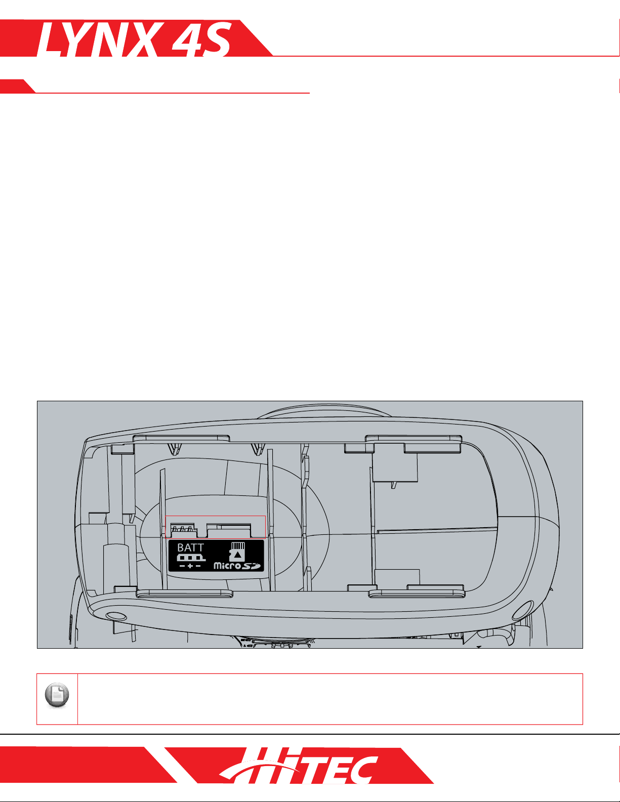
Battery Port and Micro SD Card Port:
Li-Fe, Li-Po, Ni-MH and Ni-CD batteries are supported with your Lynx 4S battery port. By inserting a micro
SD card, you can play music and telemetry voice data or expand the memory capacity for up to 30 models.
This battery port is designed to work with batteries of opposing polarity.
P10
Page 11
MANUAL: SECTION 1
Note
Changing the Position of the Steering Wheel
Installing the Extension Adapter (included) gives you the option of changing the location of the steering wheel.
The adapter improves comfort control for the Lynx 4S by allowing the steering wheel unit and throttle trigger
to be positioned at the same level.
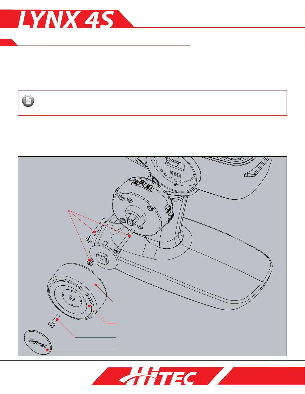
Disassembling the Steering Wheel Unit:
You will need a Phillips screwdriver to complete the following procedure. Do not force the bolts together or apart if
you encounter resistance as you can damage the unit. Work with the bolts until they slide easily into position.
1. Lift the groove under the steering wheel cover to remove it.
2. Loosen the 2.6 x 12mm screw bolt afxed to the steering wheel.
3. Pull the steering wheel adapter apart by hand to separate.
4. Loosen each of the three 28mm screw bolts from the wheel unit.
5. Disconnect the cable attached to the Steering Gimbal unit.
3x28mm Screw Bolt
Wheel Sponge
Steering Wheel
2.6x12mm Screw Bolt
Wheel Cover
P11
Page 12
MANUAL: SECTION 1
Note
Note
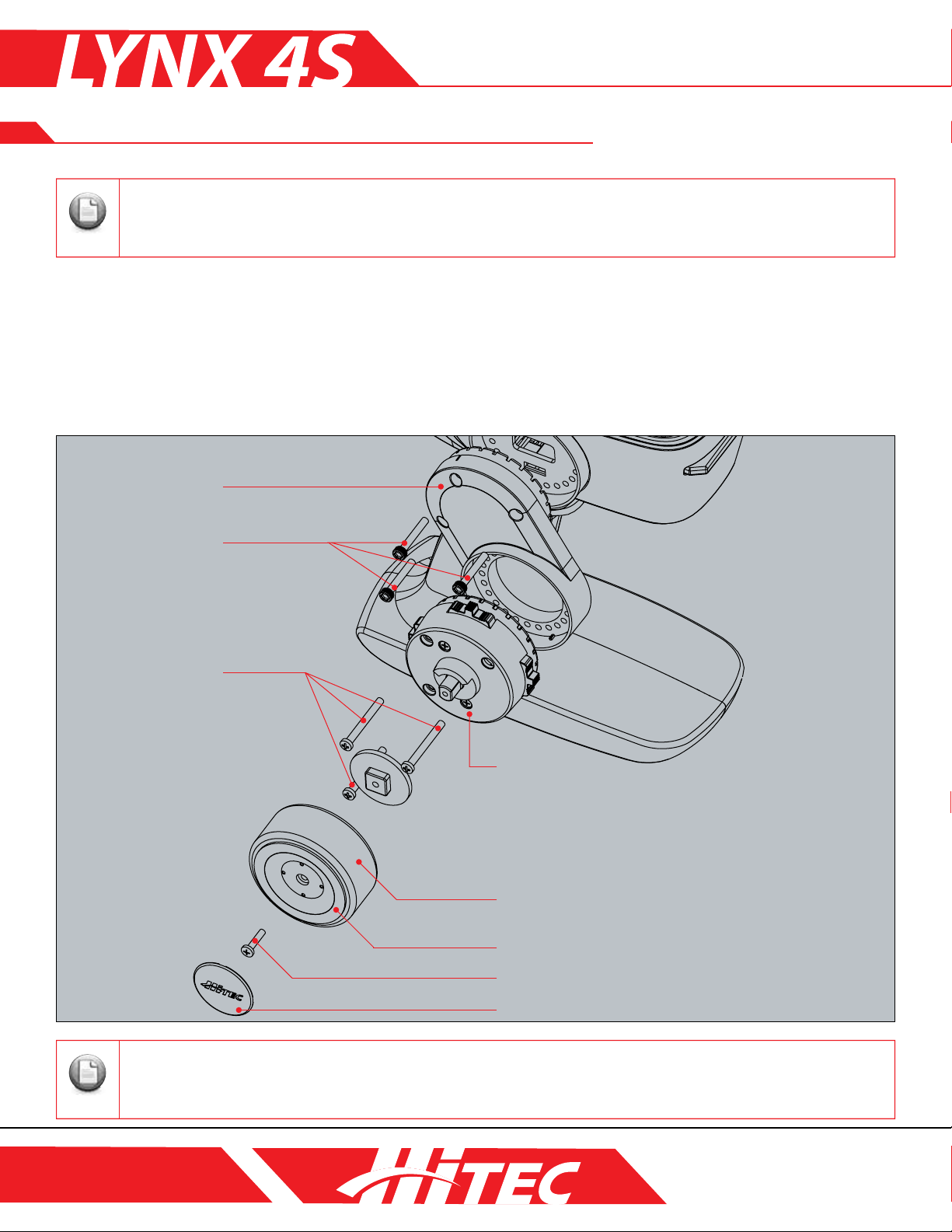
Changing the Position of the Steering Wheel (cont.)
The following procedure requires a Phillips screwdriver and 2.4mm hex wrench.
1. Connect the TX wire to the Steering Gimbal unit by passing the wire through the hole of the extension adapter.
2. Afx the extension adapter to the Lynx 4S by inserting 3 20mm hex bolts into the face of the adapter using
your 2. 5mm hex wrench.
3. Attach the wheel unit using the 3 28mm screw bolts.
4. Attach the steering wheel using the 2.6X12mm screw bolt.
5. Snap the steering wheel cover back in place.
Extension Adapter
3x20mm Hex Bolt
3x28mm Screw Bolt
Wheel Unit
Wheel Sponge
Steering Wheel
2.6x12mm Screw Bolt
Wheel Cover
Be mindful when handling the sharp ends of the wire.
P12
Page 13
MANUAL: SECTION 1
Note
Note
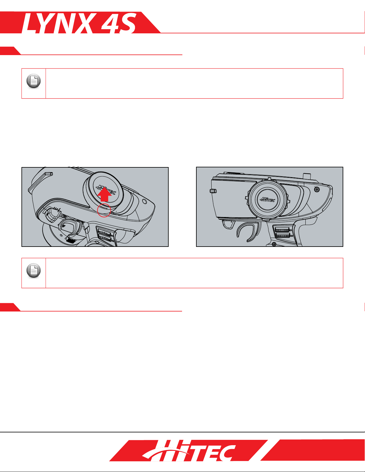
Modifying for Left-Hand Users
The following procedure requires a Phillips screwdriver.
1. Disassemble the steering wheel unit. Refer to Page 11 for a detailed explanation.
2. Lift up on the groove under the steering wheel cover located on the back of the radio to separate. Both
front and back covers should now be removed.
3. Push the wire system exposed in the front of the Lynx 4S back through the rear opening you just uncovered.
4. Put the TX back together in reverse order of disassembly after connecting the wire to the wheel unit.
5. Reattach the battery cover on the opposite side.
Be mindful when handling the sharp ends of the wire.
Rubber Grip and Neck Strap
As the owner of a Lynx 4S, you have the ability to replace the factory grip rubber with one more suitable
to your grip size. You may also choose to install a neck strap holder if you’ve found your R/C experience
necessitates it.
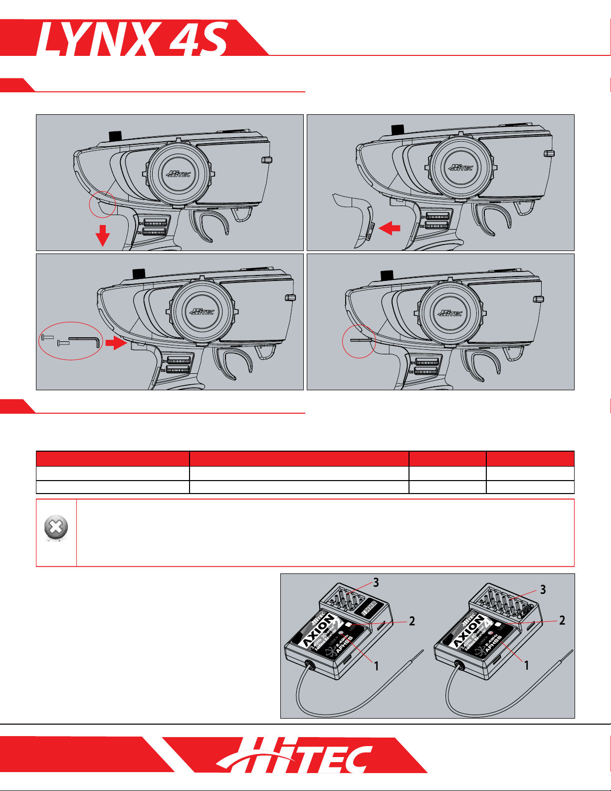
1. Pull down and out on the grip rubber in the direction pictured below.
2. Separate the grip rubber completely.
3. Attach the holder mount with two screws to the underside of the grip rubber as indicated.
4. Push the grip rubber back into place.
5. If you are replacing the grip rubber with a thicker version, simply remove the original as described in steps 1 and 2.
P13
Page 14
MANUAL: SECTION 1
Warning
Note
TipTip
Tip
Caution
Rubber Grip and Neck Strap (cont.)
Receiver
Hitec’s unique AFHSS (Adaptive Frequency Hopping Spread Spectrum) 2.4GHz system achieves new levels of
outstanding performance and stability.
Receiver Model Model Size Weight Stock Number
AXION 2
AXION 4
1. The receiver antenna should never be placed near the engine, metal parts, or high current batteries.
2.To prevent damage to the antenna, do not bend them beyond a 90 degree angle.
3. Adhere Velcro or double-sided tape directly to the bottom of the receiver to absorb shock during use.
4. When the LED indicator blinks irregularly, an unstable frequency environment is indicated. Cease use and assess your
surroundings for the possible cause.
AXION 2 & AXION 4:
1. Function Button
Used for linking the receiver to a transmitter.
2. LED Status Indicator
Indicates the set-up process codes and current
status of AXION receivers.
3. Channel Output and Battery Input Ports
These ports are for batteries, servos, and other
accessories.
1.26 x 0.87 x 0.43in (32 x 22.3 x 11mm)
1.26 x 0.87 x 0.43in (32 x 22.3 x 11mm)
0.25oz (7.0g)
0.25oz (7.0g)
27724
27824
P14
Page 15
Receiver (cont.)
5
MANUAL: SECTION 1
4
1
2
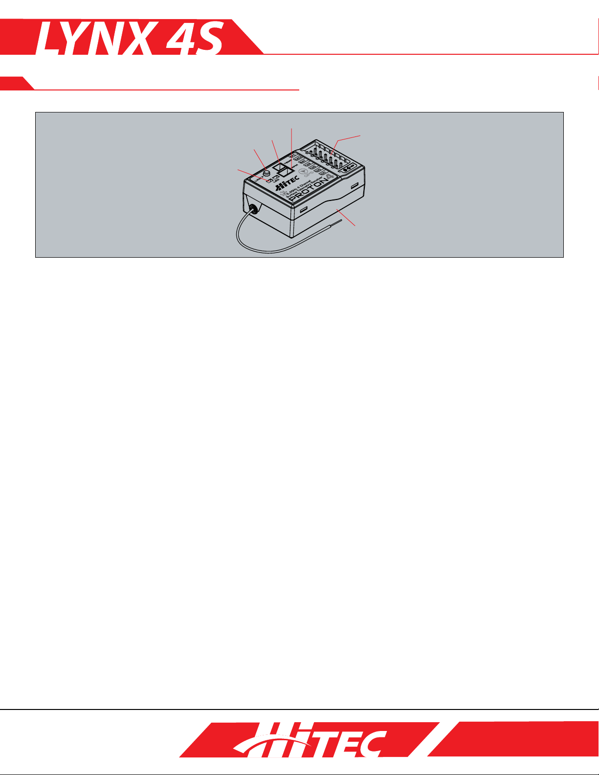
Proton 4:
1. Function Button:
Used for linking the receiver to a transmitter.
2. LED Status Indicator:
Indicates the set-up process codes and the current status of a Proton 4 receiver.
3. Channel Output and Battery Input Ports:
These ports are for batteries, servos and other accessories.
4. Temp Port:
The temperature of your model can be checked via a temperature sensor.
A temperature alarm can also be set.
3
6
5. RPM Port:
Checks RPM and speed with an RPM sensor.
6. GPS Sensor (installed):
A GPS sensor is factory-installed in the Proton 4 to gauge your car speed.
Operating Voltage:
Accepts four to six cell rechargeable NiMH, NiCD, or LiPo batteries (4.8~7.4V).
Selecting the appropriate voltage depends on the capabilities of the servos you intend to use.
HTS-TEMP (Temperature Sensor):
A temp sensor can be used by plugging it into the PROTON 4 receiver without a sensor station. Attach the
sensor to a target surface such as a motor, an ESC, or an engine. Gauge Range: 0~250 degrees C, 32~482
degrees F.
HTS-MRPM (RPM Sensor):
An RPM sensor can be used by plugging it into the Proton 4 receiver without a sensor station. Attach the
sensor to a target surface like a spur gear or y wheel. Gauge Range: 0~99999 RPM.
GPS Sensor (Built-in RX Type):
A GPS speed sensor is factory-installed in the Proton 4 receiver. You can gauge your car speed on the Lynx 4S
screen by using the Proton 4 receiver without any attachments. Range : 0~250km/H. Remember to use your
GPS sensor outdoors only as it will not receive satellite information inside.
P15
Page 16
MANUAL: SECTION 1
Note
Receiver Installation
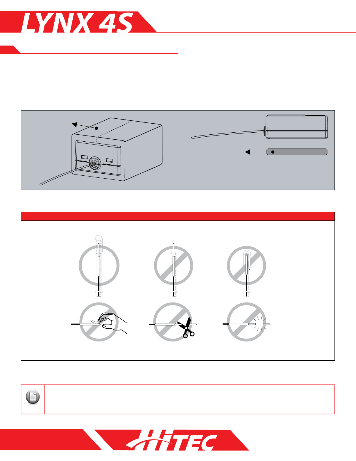
Receivers depend on sensitive technology. Do not expose your receiver to jarring vibrations, shock, or dust.
Remember to take appropriate measures, like using sponge pads or thick, double-sided tape, to insulate your
receiver against damaging forces. Do not bend or cut the ends of the 2.4GHz RX’s antenna wire. Please refer
to the picture below for the proper installation method.
Sponge Pad
Double-Sided Tape
WARNING
You can protect the receiver’s antenna by encasing them in rubber tubing.
Do not bend the antenna. Do not cut the antenna. Do not use broken antenna.
Please install receivers away from batteries, motors, ESCs or engines that generate noise. The receiver’s antenna are
especially susceptible to audio interference.
P16
Page 17
MANUAL: SECTION 1
Note
Note
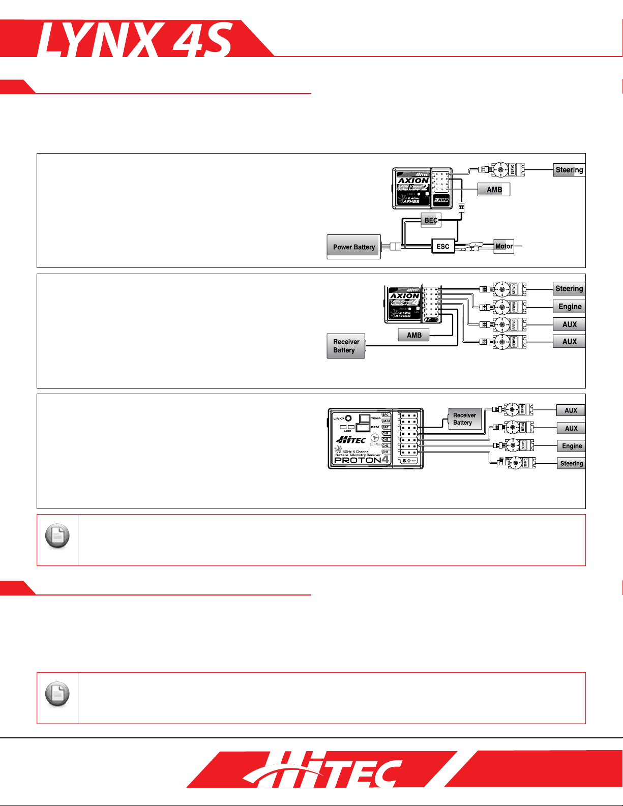
Receiver Connection Diagrams
In the case of an R/C car model, install servos as depicted below. The diagram shown here illustrates proper
installation of 2 servos in a 2-channel car model system which can be changed by installing an ESC or engine.
Receiver Connection Diagrams (AXION 2):
Shown: Electric-powered car with an Electric Speed
Controller. Use this method on electrically-powered
motor vehicles, as the ESC will provide power to the
receiver and servo systems.
Receiver Connection Diagrams (AXION 4):
Shown: In the case of glow, gas, or electric- powered
cars using a separate receiver battery supply,
follow the connection set-up pictured here.
Note: Requires 2-cell LiPo/LiFe batteries or 4.8~7.2V
4-6-cell NiMH/NiCD batteries.
Receiver Connection Diagrams (PROTON 4):
Shown: In the case of glow, gas, or electric- powered
cars using a separate receiver battery supply,
follow the connection set-up pictured here.
Note: Requires 2-cell LiPo/LiFe batteries or 4.8~7. 2V
4-6- cell NiMH/NiCD batteries.
ESC, servos, engines and other items are sold separately. Refer to the MIX menu when using all 4 channels with the
mixing function.
Charging
Charging Your Battery:
The Lynx 4S radio set includes a NiMH 4-cell battery for your convenience. We recommend using Hitec’s
overnight charger (CG-S82 220V/ CG-S85 110V) for your battery charging needs.
Depending on the country of purchase, the CG-S82 (220V) / CG-S85 (110V) overnight chargers may not be included
with your Lynx 4S package. Do not use CG-S83/S85 Hitec overnight chargers with LiPo/LiFe batteries.
P17
Page 18

Charging (cont.)
Note
Note
Note
Although an overnight charger is preferred, you have other options when charging your batteries. If you do not
currently own an overnight charger, remove the battery from your radio and charge the TX battery with a charger
approved for your battery type.
When charging with a charger of your own, set the charging amperage to 1A.
MANUAL: SECTION 1
Charging with CG-S82 (220V)/ CG-S85 (110V):
1. Connect the plug for the overnight charger to the charging port on your Lynx 4S.
2. A red light will glow to indicate active charging.
3. A green light will glow when the device is fully charged.
If your Lynx 4S is turned on at the time you connect your overnight charger to the charging port, power to the radio
will cut automatically.
P18
Page 19

MANUAL: SECTION 1
Note
Main Display
The main display shows general information regarding the operation of the Lynx 4S with your R/C models. The
display is customizable by the user.
1. Model Name 11.Signal
2. Multi-Screen
3. TImer
4. Battery
5. AMB Number 6. [T2] Throttle Trim
1. Model Name:
Indicates the current operating model name and number.
2. Multi-Screen:
Option to change the display to show logo, name of user, timer, etc.
3. Timer:
Total length of usage time after the power has been turned on.
4. Battery:
Displays the voltage of the radio’s battery.
5. AMB Number:
Personal transponder number, which identies your model when racing against other models and allows you to
read your car’s timing and scoring output.
6. [T2] Throttle Trim:
Shows current throttle trim value. Default position is linked with the T2 switch.
10. [D1] Dual Rate Value
9. [D2] ATL_Setting
8. Receiver Type
7. [T1] Steering Trim
7. [T1] Steering Trim:
Shows the current steering trim value. Default position is liked with the T1 switch.
8. Receiver Type:
Shows receiver detail information as well as the status of the BOOST function.
9. [D2] ATL_Setting:
Shows current ATL settings. Default position is linked with the D2 dial.
10. [D1] Dual Rate Value:
Shows the current dual rate value. Default position is linked with the D1 dial.
11. Signal:
Shows the radio’s signal or frequency.
Information on the main display may be saved to memory.
P19
Page 20

MANUAL: SECTION 1
Sub Menus
MODEL PROGRAMING SET 1 [Pages 22 – 27]
From this screen you can program the following items:
Servo Reverse (R.E.V.), Endpoint Adjustments (E.P.A.), Brake Rate (ATL), AntiLock Brake (ABS), Steering Exponential (ST-EXP), Brake Exponential (BKEXP), Throttle Exponential (TH-EXP), Steering Dual Rate (ST-D/R), Sub Trims
(S-TRIM) and FAILSAFE.
MODEL PROGRAMING SET 2 [Pages 28 – 39]
From this screen you can program the following items:
Auto Boost (BOOST), Steering Servo Speed (ST-SPD), Throttle Servo Speed
(TH-SPD), Throttle Mode (TH-MOD), Idle Up/Down (IDL-UP), Race, Lap and
Countdown Timer (TIMER), LAP LISTs, Switch Settings (SWITCH) Radio Dial
Settings (DIAL) and Channel Mixing (MIX).
SYSTEM PROGRAMMING [Pages 40 – 50]
From this screen you can program these system settings:
Steering Adjustment (ST-ADJ), Throttle Adjustment (TH-ADJ), Receiver Binding
(RX-BIND), Radio Frequency Scanning (RF-SCAN), SERVO Monitor, Telemetry
Sensors setup (SENSOR), System MANAGEMENT, TELEMETRY Display,
VIBRATION Setting and BATTERY Type Settings.
MODEL MANAGEMENT [Pages 51 – 52]
From the model management screen do the following:
NAME your model, DELETE a model from the memory, COPY a model to an
empty memory slot, and CHANGE the active model.
SD CARD MANAGEMENT [Pages 53 – 55]
In this section you can perform the following tasks:
NAME the SD card, DELETE model data from the SD card, IMPORT and
EXPORT models from the SD card, setup and adjust the VOICE functions and
play MUSIC from the SD card.
P20
Page 21

MANUAL: SECTION 2
Note
Note
REV (Servo Reverse)
The REV function enables the user to adjust servo direction with changes to steering, throttle, and
maneuvering the 3CH and 4CH models (settings are either clockwise or counterclockwise).
1. From the main screen, press the Main Dial button to enter the function menu.
2. With the “SET 1/2” tab highlighted, press the Main Dial button to access
the function options below. Select REV by pressing the Main Dial again.
3. Scroll through the options using the Main Dial scroll feature and click the
Main Dial once to select your channel.
If you have ne-tuned the direction of your servo with sub-trim adjustments, the sub-trim settings will take affect on
the opposite side when you apply the servo-reverse function.
EPA (End Point Adjust)
This function allows the user to set the maximum operating angle of the servo that is linked to the transmitter.
This option comes in handy if the turning radius of the car varies from left to right due to the condition of the
vehicle. (Note: the setting ranges from a Min. 0~ Max. 120 for each channel.)
1. Press the Main Dial button from the home screen to access the function menu.
2. Select EPA from the SET 1/2 tab by clicking on SET 1/2 rst and then
EPA when highlighted.
3. Use the Main Dial to scroll through your options and click the Main Dial
to select the appropriate channel.
4. After selecting your channel, maneuver the trigger to control steering and throttle.
The EPA function is pre-set to the maximum working angle of the servo. If that setting has been altered, it may affect
EPA functionality. If you wish to set the maximum angle of the servo with EPA settings, it is recommended that you
return the EPA to its default setting. See below.
[ATL] = Page 22: default= 100
[ST-D/R] = Page 26: default= 100
[S-TRIM] = (Page XX): default position for each channel= 0.
P21
Page 22

MANUAL: SECTION 2
Note
Note
ATL (Brake Rate)
The ATL (Adjustable Travel Limiter) affects the braking response of your vehicle. A higher ATL value
corresponds to a rmer braking response (a 100% value is the equivalent of slamming on your brakes), while a
lower setting results in a more gradual stop.
1. The ATL value setting can be adjusted with the D2 Dial [under MIX mode 1] shortcut.
2. Alternatively, you can access the ATL function by pressing the Main Dial from the home screen to view the
function menu.
3. Next, select ATL from the SET 1/2 tab by clicking on the tab and then using the Main Dial button to scroll
and highlight “ATL.”
4. Press the Main Dial button to select. Adjust to the appropriate value.
5. You can check the current ATL value setting on the home screen which is viewable on the right-hand side.
A.T.L. is a supporting function of the Brake EPA settings.
ABS (Anti-Lock Brake)
ABS improves braking sensitivity, cornering, and stability under adverse road conditions.
1. Press the Main Dial to view the function menu.
2. Select “ABS” from the SET 1/2 tab by clicking the Main Dial button when
highlighted.
3. Press the Main Dial button to select the channel.
The user must set a lower CYL value when using low speed servos. Be aware that excessive use of ABS may cause
damage to your servos.
P22
Page 23

MANUAL: SECTION 2
Note
E50%
Steering operation
N50%
Steering operation
LR N
50% 50%
A.B.S operation range
indicated by “*”
A.B.S operation range
indicated by “*”
A.B.S operation range
indicated by “*”
L
R
N
50% 50%
ABS (Anti-Lock Brake cont.)
Terms for ABS Setting:
USE: Indicates the status (ON/OFF) of ABS [default: OFF]
ON: The starting point of ABS operation when maneuvering the brake trigger [default: 30%]
POW: The angle of the ABS brake power [default: 50%]
DLY: Delays the time of ABS operation after setting the ABS starting point [default: 0ms]
CYL: The recurring engagement time of the ABS brake [default: 100ms]
STL: Steering mixing [default position: OFF]
You may change the ON/OFF steering setting while brakes are activated.
See below for the ABS operating range when steering under an N50% and E50% setting:
ST-EXP (Steering Exponential)
Enables the user to set their preferred servo operating conditions for steering, with steering response ranging
from more to less sensitive.
1. Press the Main Dial to enter the function menu.
2. Select ST-EXP from the SET 1/2 tab using your Main Dial button’s scroll and click functions.
3. Press the Main Dial button to select the appropriate option.
ST-EXP may be adjusted with an external switch. Please refer to Page 37 for details.
P23
Page 24

MANUAL: SECTION 2
Note
Note
BK-EXP (Brake Exponential)
Sets the servo operating conditions for brake direction. By adjusting these settings, you can create a more or
less sensitive braking response for your vehicle.
1. Press the Main Dial button to view the function menu.
2. Select BK-EXP from the SET 1/2 tab with the Main Dial button’s scroll and click functions.
3. Press the Main Dial button to select the appropriate option.
BK-EXP may be adjusted with an external switch. Please refer to Page 37 for details.
TH-EXP (Throttle Exponential)
Enables the user to set their preferred servo operating conditions for throttle, with throttle adjustments that
can create either a rougher or smoother acceleration experience.
EXP Curve 1P Mode Curve 3P Curve 5P Mode Curve
1. Users have 4 Curve options when setting up TH-EXP.
2. Press the Main Dial to access the function menu.
3. Select TH-EXP from the SET 1/2 tab with the Main Dial button’s scroll and click functions.
4. Click the Main Dial when you have selected the desired option.
TH-EXP may be adjusted with an external switch. Please refer to Page 37 for details.
P24
Page 25

MANUAL: SECTION 2
Note
Note
ST-D/R (Steering Dual Rate)
Users have the option of increasing or decreasing the servo operation angle with the dual rate adjusting dial
[Default: 100].
1. ST-D/R function is adjusted by the D1 Dial [under MIX mode 1].
2. Press the Main Dial button from the home screen to access the function menu.
3. Select ST-D/R under the SET 1/2 tab with the scroll/click function of the Main Dial button.
4. When the desired option is highlighted, click the Main Dial button to select.
5. The current value of the ST-D/R function is viewable on the right of the home screen in graph form.
Dual Rate is linked to the EPA function, so check the operating angle of the servo before engaging your vehicle. STD/R may be adjusted by external switch. Please refer to Page 38 for details.
S-TRIM (Sub Trim)
If the vehicle drives off-center or when the position of the servo affects proper functioning of the servo horn,
change the position of the servo [Default: 0].
MIX Mode 1 MIX Mode 10
1. MIX function settings may cause changes to the channel names.
2. Press the Main Dial button to access the function menu.
3. Select S-Trim from the SET 1/2 tab by using the Main Dial’s scroll and click functions.
4. Click the Mai Dial button when the desired option is highlighted to select.
5. The current sub-trim value is viewable in graph form on the home screen.
Set the S-Trim to ‘0’ and review the location of the horn for proper alignment before installing the servo(s) in your
vehicle. Use the S-TRIM function to adjust and conrm the appropriate center position. If there is a change to the
S-Trim set position while driving, use the Sub-trim to re-adjust.
P25
Page 26

MANUAL: SECTION 2
Note
FAIL-SAFE
Engaging the Fail-Safe option will move servos to a pre-saved position should you experience signal
interference. As a safety precaution, it is highly recommended that the Fail-Safe mode is activated at all times.
Hold Mode (HOLD):
Servo will maintain its current position when the receiver is not capable of receiving signals.
Set up Mode (SET):
Servo moves to a pre-set position when the receiver is not capable of receiving signals.
1. Press the Main Dial button to access the function menu.
2. Select FAIL-SAFE under the SET 1/2 tab by using the Main Dial button’s scroll and click functions.
3. Select HOLD or SET mode as desired after choosing the channel to be changed.
4. Adjust the location of the servo under the ‘FAIL-SAFE ON’ condition by using the trigger, dial, or switch.
5. To save the current FAIL-SAFE value, press the Main Dial button for a count of a few seconds.
6. After you nish adjusting the settings for each channel, press [SEND] and check the Sending display that will
conrm the settings you selected.
The FAIL-SAFE function automatically returns to the default set position when the user changes the type under
MIX function. Please re-set the FAIL-SAFE function when this happens. We recommend engaging the brakes to stop
engine-powered vehicles and backing off the throttle to stop electric models.
P26
Page 27

MANUAL: SECTION 2
Note
BOOST (Auto Boost)
Quick start is not suitable under slippery road conditions. In conditions prone to tire spin, the BOOST
function creates a smoother acceleration.
BOOST Setting Display BOOST Function on Main Display
USE: Indicates whether the BOOST function is ON or OFF [default: OFF].
MAX: sets the timer to automatically turn OFF the BOOST function [default: 5s]. (This setting is only
maintained when the throttle trigger is at 100%)
TG.P: The point at which the BOOST power starts [default: 10%].
PW.P: The power settings under which the BOOST function is operating [default: 100%].
1. Press the Main Dial button to view the function menu.
2. Select BOOST under the SET 2/2 tab by using the Main Dial’s scroll and click functions.
3. Press the Main Dial button to select the channel.
4. The BOOST function automatically shuts OFF after use.
5. You may check the status of the BOOST setting on the graph located on the home screen.
S T-SPD (Steering Servo Speed)
ST-SPD sets the speed for the clockwise/ counterclockwise movement of the servo. It allows for more stable
driving conditions for the vehicle on the road.
ST-SPD Setting Display Crawler MIX Function on Main Display
1. Press the Main Dial button to access the function menu.
2. Select SP-SPD under the SET 2/2 tab.
3. Press the Main Dial button to select the channel.
4. Note that lower speed corresponds to a lower set value.
5. The maximum speed cannot be set to exceed the original speed of the servo. Likewise, slower operation
does not affect the speed of the servo.
ST-SPD may be adjusted by external switch. Please refer to Page 37 for details.
P27
Page 28

MANUAL: SECTION 2
Note
Note
TH-SPD (Throttle Servo Speed)
TH-SPD enables the user to set the momentum connected to the throttle servo or ESC. It allows for more
stable driving control under different road conditions.
1. TH-SPD has four mode settings.
2. Press the Main Dial button to enter the function menu.
3. Select TH-SPD on the SET 2/2 tab by using the Main Dial button’s scroll and click function.
4. Press the Main Dial button to select the channel.
5. Note that a lower speed corresponds to a lower value setting.
6. The maximum speed cannot be set to exceed the original speed of the servo. Likewise, slower operation
does not affect the speed of the servo.
TH-SPD may be adjusted by external switch. Please refer to Page 37 for details.
TH-MOD (Throttle Mode)
The R.E.V. function enables the user to adjust servo direction with changes to steering, throttle, and
maneuvering the 3CH and 4CH models (settings are either clockwise or counterclockwise).
1. Press the Main Dial button to enter the function menu.
2. Select TH-MOD on the SET 2/2 tab.
3. Select the target setup by clicking the Main Dial button.
Please disconnect the motor from the ESC to disable the Nitro /Gas engine before adjusting TH MODE.
P28
Page 29

MANUAL: SECTION 2
Note
IDL-UP (Idle Up/Down)
The user has the option to adjust the engine’s idling parameters. You can prevent idling during vehicle refuel, or
you can assign an idling period when you brake.
1. Press the Main Dial button to enter the function menu.
2. Select IDLE UP under the SET 2/2 tab.
3. Select the IDLE UP value suitable for your needs.
TH: When the TH function is ON, range of activation can be set [Range: B50 / OFF / H50].
MAX: When the MAX function is ON, the IDLE UP time frame can be set. [Range: OFF / 1-60secs]
When the set time has elapsed, the function will shut off automatically.
When IDLE UP is activated, its ON status is visible via a blinking LED light on-screen.
Timer (Race Timer)
Allows the user to monitor relevant clock speeds like total run time, refuel time, and fastest lap time.
MODE: Select the desired timer function.
ALARM: Set the target alarm time.
PRE: Set a pre-alarm notication. For example, setting a 35 second pre-alarm will sound a warning 35 seconds
before your start time.
TR: Activates the timer by moving the throttle trigger.
READY: Clicking Ready will start the timer.
RESET: Resets the timer.
1. Press the Main Dial button to access the function menu.
2. Select ‘Timer’ under the SET 2/2 tab.
3. Set up the timer function suitable to your needs.
4. Timer will start when you click ‘READY’ or pull the throttle trigger.
P29
Page 30

MANUAL: SECTION 2
Note
Note
Note
Timer (Race Timer cont.)
Most of the switches can be assigned a TIMER START by switch section. Timers start or stop according to assigned
switch. Please refer to Page 37 for more detail.
You can view the current timer function on the main screen. Please refer to Page 52 for more details.
Countdown Timer
The DOWN TIMER option is handy when the user wants to check a certain time, like refuel time, repeatedly.
MODE: Select the desired timer function.
ALARM: Set the target alarm time.
PRE: Set a pre-alarm notication. For example, setting a 35 second pre-alarm will sound a warning 35 seconds
before your start time.
TR: Activates the timer by moving the throttle trigger.
READY: Clicking Ready will start the timer.
RESET: Resets the timer.
1. Press the Main Dial button to access the function menu.
2. Select ‘Timer’ under the SET 2/2 tab.
3. Set up the timer function suitable to your needs.
4. Timer will start when you click ‘READY’ or pull the throttle trigger.
Most of the switches can be assigned a TIMER START. Timers start or stop according to assigned switch. Please refer
to Page 37 for more details.
P30
Page 31

MANUAL: SECTION 2
Note
Lap Timer
Allows the user to view details of each lap. To view all laps, go to the Lap List.
MODE: Select the desired timer function.
ALARM: Set the target alarm time.
PRE: Set a pre-alarm notication. For example, setting a 35 second pre-alarm will sound a warning 35 seconds
before your start time.
TR: Activates the timer by moving the throttle trigger.
READY: Clicking Ready will start the timer.
RESET: Resets the timer.
1. Press the Main Dial button to access the function menu.
2. Select ‘Timer’ under the SET 2/2 tab.
3. Set up the timer function suitable to your needs.
4. Timer will start when you click ‘READY’ or pull the throttle trigger.
Each lap can be stored by assigning a ‘TIMER CAPTURE’ switch. Refer to Page 37 for more details.
Lap List (Lap Time Listings)
The lap list stores average and individual lap times for later viewing.
No Data: There is no LAP data available at this time.
AVG: Average lap time.
ALL: Total run time.
P31
Page 32

MANUAL: SECTION 2
Note
Note
Lap List (Lap Time Listings cont.)
1. Press the Main Dial button to access the function menu.
2. Select ‘Timer’ under the SET 2/2 tab.
3. Check the Lap List by clicking the Main Dial over the highlighted option.
The Lap List will be deleted upon restarting the Lap Timer or powering off.
Switch (Switch Functions, Assignments & Settings)
All switch functions and dials can be assigned under the Switch menu located on the Set 2/2 tab.
FUNC: Set the desired function that corresponds to your switches from a list of options.
DIR: May be set to normal or reverse or to ON/OFF for an assigned switch.
TYPE: An option for certain switches that denes the way to use them, either pressed or toggle.
TOGGLE: To activate the function, “toggle” the assigned switch.
PRESSED: If “pressed” is dened as the method of activation, pressing the switch will activate the
corresponding function.
3SRATE: Press the switch to change the value for Minimum, Neutral, or Maximum rotation.
1. Press the Main Dial button to access the function menu.
2. Select ‘SWITCH’ under the SET 2/2 tab.
3. Scroll through the options with the Main Dial button. When the desired switch is highlighted, click the button
to set up the parameters of that function.
4. Double check your switch buttons to ensure they were appropriately linked to the desired function before
operating your model.
There can only be one function assigned to each switch.
P32
Page 33

Assignable Switch List
Function Switch Type
NOT LINK
4WS FS
4WS RS
4WS FR-N
4WS FR-S
4WS-S
4WS-3
TH-MIX
AUX1
AUX2
TELEVOICE/U
IDLE-UP/U
ABS/U
ST-EXP/U
BK-EXP/U
TH-EXP/U
TIMER START
TIMER CAPTURE
TIMER R/START
D/R
ATL
T-A ST
T-B TH
T-C AUX1
T-D AUX2
S-A ST
S-B TH
S-C AUX1
S-D AUX2
ST-SPD +
ST-SPD TH-SPD1
TH-SPD2
TH-SPD3
ST-EXP
BK-EXP
TH-EXP
T-A F-ST
T-B F-TH
T-C R-ST
T-D R-TH
S-A F-ST
S-B F-TH
S-C R-ST
S-D R-TH
T-ST
T-TH
B1
O
X
X
X
X
O
X
X
O
O
O
O
O
O
O
O
X
X
X
X
X
X
X
X
X
X
X
X
X
X
X
X
X
X
X
X
X
X
X
X
X
X
X
X
X
X
X
B2
O
X
X
X
X
O
O
O
O
O
O
O
O
O
O
O
O
O
O
X
X
X
X
X
X
X
X
X
X
X
X
X
X
X
X
X
X
X
X
X
X
X
X
X
X
X
X
D3
O
X
X
X
X
O
O
O
O
O
O
O
O
O
O
O
O
O
O
X
X
X
X
X
X
X
X
X
X
X
X
X
X
X
X
X
X
X
X
X
X
X
X
X
X
X
X
MANUAL: SECTION 2
SW1
T1
O
X
X
X
X
O
O
O
O
O
X
X
X
X
X
X
X
X
X
O
O
O
O
O
O
O
O
O
O
O
O
O
O
O
O
O
O
O
O
O
O
O
O
O
O
O
O
T2
O
X
X
X
X
O
O
O
O
O
X
X
X
X
X
X
X
X
X
O
O
O
O
O
O
O
O
O
O
O
O
O
O
O
O
O
O
O
O
O
O
O
O
O
O
O
O
T3
O
X
X
X
X
O
O
O
O
O
X
X
X
X
X
X
X
X
X
O
O
O
O
O
O
O
O
O
O
O
O
O
O
O
O
O
O
O
O
O
O
O
O
O
O
O
O
T1-
T3+
T2+
T1+
O
X
X
X
X
X
O
O
O
O
X
X
X
X
X
X
X
X
X
X
X
X
X
X
X
X
X
X
X
X
X
X
X
X
X
X
X
X
X
X
X
X
X
X
X
X
X
O
O
O
O
O
O
O
O
O
O
X
X
X
X
X
X
X
X
X
X
X
X
X
X
X
X
X
X
X
X
X
X
X
X
X
X
X
X
X
X
X
X
X
X
X
X
X
X
X
X
X
X
X
X
X
X
X
X
X
X
X
X
X
X
X
X
X
X
X
X
X
X
X
X
X
X
X
X
X
X
X
X
X
X
X
X
X
X
X
X
X
X
X
X
O
O
O
O
O
O
O
O
O
O
X
X
X
X
X
X
X
X
X
X
X
X
X
X
X
X
X
X
X
X
X
X
X
X
X
X
X
X
X
X
X
X
X
X
X
X
X
X
X
X
X
X
X
X
X
X
X
X
X
X
X
X
X
X
X
X
X
X
X
X
X
X
X
X
X
X
X
X
X
X
X
X
X
X
X
X
X
X
X
X
X
X
X
X
T2-
O
O
O
O
O
X
X
X
X
X
X
X
X
X
X
X
X
X
X
X
X
X
X
X
X
X
X
X
X
X
X
X
X
X
X
X
X
X
X
X
X
X
X
X
X
X
X
T3-
O
O
O
O
O
X
X
X
X
X
X
X
X
X
X
X
X
X
X
X
X
X
X
X
X
X
X
X
X
X
X
X
X
X
X
X
X
X
X
X
X
X
X
X
X
X
X
P33
Page 34

Function of Switch
Function Description
NOT LINK
4WS FS
4WS RS
4WS FR-N
4WS FR-S
4WS-S
4WS-3
TH-MIX
AUX1
AUX2
TELEVOICE/U
IDLE-UP/U
ABS/U
ST-EXP/U
BK-EXP/U
TH-EXP/U
TIMER START
TIMER CAPTURE
TIMER R/START
D/R
ATL
T-A ST
T-B TH
T-C AUX1
T-D AUX2
S-A ST
S-B TH
S-C AUX1
S-D AUX2
ST-SPD +
ST-SPD TH-SPD1
TH-SPD2
TH-SPD3
ST-EXP
BK-EXP
TH-EXP
T-A F-ST
T-B F-TH
T-C R-ST
T-D R-TH
S-A F-ST
S-B F-TH
S-C R-ST
S-D R-TH
T-ST
T-TH
MANUAL: SECTION 2
Clear Assigned function
Change to Front Wheel Steer
Change to Rear Wheel Steer
Change to Front and Rear Steer
Change to Front and Rear Steer (Same Phase)
Change to Rear Steer or Back to 4WS-3 Status
Change Status 4WS FR-N/4WS FR-S/4WS FS
Front Motor, Rear Motor can be controlled at the same time or seperately
Control 3CH servo from the receiver
Control 4CH servo from the receiver
Turn On/Off Telemetry voice
Turn On/Off IDLE-UP
Turn On/Off ABS
Turn On/Off ST-EXP
Turn On/Off BK-EXP
Turn On/Off TH-EXP
Start/Stop Timer
Record each Lap in LAP TIMER
Start/Reset Timer
Dual Rate
ATL
Adjust 1CH Trim
Adjust 2CH Trim
Adjust 3CH Trim
Adjust 4CH Trim
Adjust 1CH Sub-Trim
Adjust 2CH Sub-Trim
Adjust 3CH Sub-Trim
Adjust 4CH Sub-Trim
Change 'TURN' Servo Speed
Change 'RETURN' Servo Speed
Change 'LOW' value on 3 Step Throttle Servo Speed
Change 'MID' value on 4 Step Throttle Servo Speed
Change 'HIGH' value on 5 Step Throttle Servo Speed
Change ST-EXP
Change BK-EXP
Change '[MODE: EXP ]' Value on TH-EXP
Change Trim of Front Steering on 4WS
Change Trim of Front ESC on 4WS
Change Trim of Rear Steering on 4WS
Change Trim of Rear ESC on 4WS
Change Sub-Trim of Front Steering on 4WS
Change Sub-Trim of Front ESC on 4WS
Change Sub-Trim of Rear Steering on 4WS
Change Sub-Trim of Rear ESC on 4WS
Change Trim of Front and Rear Steering at the same time on 4WS
Change Trim of Front and Rear ESC at the same time on 4WS
P34
Page 35

MANUAL: SECTION 2
Note
Dial (Radio Dial Functions & Settings)
There are three dial positions that you may link to an R/C function of your choosing.
FUNC: Type of Function
DIR: Set to Normal /Reverse or ON/OFF.
1. Press the Main Dial button to enter the function menu.
2. Select ‘Dial ‘ under the SET 2/2 tab.
3. Use the Main Dial button to select and assign the Dial options.
4. Once set-up is complete, please double check the assigned switch before operation.
There is only one function for every switch.
P35
Page 36

Dial Function
Note
Function Switch Type
NOT LINK
AUX1
AUX2
D/R
ATL
T-A ST
T-B TH
T-C AUX1
T-D AUX2
S-A ST
S-B TH
S-C AUX1
S-D AUX2
ST-SPD +
ST-SPD TH-SPD1
TH-SPD2
TH-SPD3
ST-EXP
BK-EXP
TH-EXP
T-A F-ST
T-B F-TH
T-C R-ST
T-D R-TH
S-A F-ST
S-B F-TH
S-C R-ST
S-D R-TH
T-ST
T-TH
MANUAL: SECTION 2
D1 D2 D3
O
O
O
O
O
O
O
O
O
O
O
O
O
O
O
O
O
O
O
O
O
O
O
O
O
O
O
O
O
O
O
O
O
O
O
O
O
O
O
O
O
O
O
O
O
O
O
O
O
O
O
O
O
O
O
O
O
O
O
O
O
O
O
O
O
O
O
O
O
O
O
O
O
O
O
O
O
O
O
O
O
O
O
O
O
O
O
O
O
O
O
O
O
Depending on MIX type, Dial set-up may be limited.
P36
Page 37

MANUAL: SECTION 2
Note
Mix (Channel Mixing)
The Lynx 4S provides 11 different mixing commands suitable to your R/C needs.
1. Press the Main Dial button to access the function menu.
2. Select ‘MIX’ under the SET 2/2 tab.
3. Select the type of Mixing command by using the Main Dial button.
4. Changes will be saved after you exit the MIX set-up screen.
Be careful to select the appropriate MIX type as it may cause damage to your equipment if set up incorrectly.
Type of Mixing
TYPE 1 TYPE 2 TYPE 3 TYPE 4 TYPE 5 TYPE 6 TYPE 7 TYPE 8 TYPE 9 TYPE 10T YPE 11
CH Normal 4WSC rawler
CH1S teeringS teeringS teeringS teering
Throttle /
CH2
CH3A UX 1 Brake Brake Brake 1
CH4A UX 2 AUX 1A UX 1 Brake 2 AUX 1B rake Brake AUX 1A UX 1
No Data: There is no LAP data available at this time.
AVG: Average lap time.
Brake
Throttle
Throttle /
Brake
1/5 Scale Gas Car
Left /
Steering
Throttle
Throttle /
Brake
Right /
Steering
Left /
Steering
Throttle
Right /
Steering
Left /
Steering
Throttle /
Brake
Right /
Steering
Front /
Steering
Throttle /
Brake
Rear /
Steering
Steering
Front /
Throttle /
Throttle /
Brake
Rear /
Brake
Dual
Throttle
4WS
Front /
Steering
Front /
Throttle /
Brake
Rear /
Steering
Rear /
Throttle /
Brake
Boat
Left /
Steering
Throttle
Right /
Steering
AUX 2
ALL: Total run time.
P37
Page 38

MANUAL: SECTION 2
4WS (4 Wheel Steering)
The Lynx 4S allows the user to control both front and rear steering either together or independently. You
can control the 4WS system using TYPE 8 or TYPE 10 along with 11 different mix commands. You can assign
control of the 4WS front/rear steering to a switch button if desired.
4WS FS 4WS RS 4WS FR-S 4WS FR-N
Crawler
A function that controls Dual ESC. You can control a Dual ESC system using TYPE 9 or TYPE 10 along with 11
different mix commands. You also have the option of assigning a control switch to this function.
F-TH R-TH NORMAL
P38
Page 39

MANUAL: SECTION 3
Note
Note
ST-ADJ (Steering Adjustments)
Use this function when a mechanical steering offset has occurred.
Before After
1. Press the Main Dial button to access the function menu.
2. Select ‘ST-ADJ’ under the SYSTEM tab.
3. Turn the steering wheel left or right to adjust the corresponding values. A reading of “0 OK” represents Center.
4. If you have an OK marker on the screen, press OK to save.
Once ST-ADJ is complete, please double check the throttle setup to ensure proper operation.
TH-ADJ (Throttle Adjustments)
Use this function to tweak your throttle setting.
Before After
1. Press the Main Dial button to access the function menu.
2. Select ‘TH-ADJ’ under the SYSTEM tab.
3. Press the throttle trigger to adjust the values on-screen. A reading of “0 OK” represents neutral.
4. If you have an OK marker on the screen, press OK to save.
Once TH-ADJ is complete, please double check the throttle setup to ensure proper operation.
P39
Page 40

MANUAL: SECTION 3
Note
Note
RX-Bind (Receiver Binding)
Use the RX-BIND process when you have purchased multiple receivers or need to reset those receivers from
a previous bind. RX-BIND “binds” the transmitter to the receiver so they operate as a unit pair.
The Lynx 4S stores up to 30 models in its memory, which means users can bind up to 30 receivers to their
Lynx 4S and control each one of them independently.
Please place the Lynx 4S and receiver(s) within a 1 meter distance while binding.
Bind with AXION 2 Bind with PROTON 4
The Lynx 4S is only compatible with Hitec AFHSS Surface Receivers.
Please select the approproate receiver according to your receiver type.
AXION 2: Will bind with AXION 2
AXION 4: Will bind with AXION 4
PROTON 4: Will bind with PROTON 4
NORMAL: 14ms (Digital / Analog servo compatible)
HIGH SPEED: 7ms (Only compatible with Digital servo)
HHR SYSTEM: 4ms (Only compatible with Digital servo & Axion 2 )
Prevent serious damage to analog servos; DO NOT SELECT HIGI SPEED OR HHR SYSTEM with analog servo receivers.
Ex) Bind with AXION 2 Ex) Bind with PROTON 4
P40
Page 41

MANUAL: SECTION 3
Note
Note
RX-Bind (Receiver Binding cont.)
Lynx 4S Bind Process:
1. Press the Main Dial button to access the function menu.
2. Select ‘RX-BIND’ located under the SYSTEM tab.
3. Select the correct receiver.
4. Click ‘START’ at the bottom of the screen. Note that it will now read “BINDING.”
5. The bind is complete when the LED on the transmitter ashes in color.
Receiver Bind Process (same as AXION and PROTON):
1. Prepare the Lynx 4S for binding.
2. Press the ‘LINK’ button on the receiver and turn the power ON.
3. Once the power is on, release the ‘LINK’ button.
4. Look for a blinking red and blue LED.
5. Binding is complete when the LED glows solidly blue.
6. Press the ESC button on the transmitter twice to leave bind mode.
7. Power your receiver OFF and then back ON to check for binding.
Repeat the steps above if binding does not take.
RF-Scan (Radio Frequency Scanning)
This function improves the signal connection between your transmitter and receiver.
It is highly recommended that you use the RF-SCAN function when operating your model in a new location.
RF-SCAN clears all bind data. Once the RF-SCAN is complete, you will need to re-process the TX/RX bind.
P41
Page 42

MANUAL: SECTION 3
Note
Note
RF-Scan (Radio Frequency Scanning cont.)
1. Press the Main Dial button to access the function menu.
2. Select ‘RF-SCAN’ under the SYSTEM tab.
3. Press ‘YES’ to begin the scan.
4. Once scanning is complete, you will need to recreate the bind between your transmitter and any receivers.
Servo (Servo Monitor)
All servo operations can be checked by graph on-screen using the ‘TEST’ function to assess their condition.
The number assigned to the TEST value relates to test speed.
1. Press the Main Dial button to access the function menu.
2. Select ‘SERVO’ under the SYSTEM tab.
3. Move all servos connected with the receiver to check their condition.
4. You can adjust ‘TEST’ speed by changing the numbers next to ‘TEST.’
Please DO NOT activate the ‘TEST’ function if the servos are already installed in the vehicle as it may cause damage to the
model or servo failure.
Sensor (Telemetry Sensor Setup)
Hitec’s AFHSS (Advanced Frequency Hopping Spread Spectrum) is supported by bi-directional communication
known as telemetry. With this function, users can check the data output of the telemetry sensors on-screen
and activate warnings to sound from the Lynx 4S speakers or earphone port.
The telemetry function is only compatible with a PROTON 4 receiver.
P42
Page 43

MANUAL: SECTION 3
Note
Note
Note
Sensor (Telemetry Sensor Setup cont.)
The option to set-up warning sounds is available through each sensor’s function screen.
TEMP (Temperature Sensor):
Temperature data gathered by the temperature sensor is displayed on-screen. Users can also set a warning
level and spoken audio warning for this function.
TMP: Temperature via TEMP sensor.
SPEAK: Activate to issue an audio warning via the Lynx 4S speakers.
USE: Issues a warning message when activated.
WARNING: Set the desired warning level.
UNIT: Set the unit of temperature (F or C).
1. Press the Main Dial to access the function menu.
2. Select ‘SERVO’ under the SYSTEM tab.
3. Select ‘TEMP’ from the menu and adjust the options to your preference.
This function is only available when the temperature sensor is connected to your Proton 4 receiver.
To use the ‘SPEAK’ function, a micro SD memory card is required. It is recommended that users save their warning
les to the micro SD memory card provided through the Hitec website. Please visit page XX for more details.
There will be a time delay between the read-out of the audio data and when the data is displayed on-screen.
P43
Page 44

MANUAL: SECTION 3
Note
Note
Note
Sensor (Telemetry Sensor Setup cont.)
VOLT (Voltage Sensor):
Data from the voltage sensor will be displayed on-screen. In this section, users are shown how to set a VOLT
warning level and voice output.
SPEAK: Activate to issue an audio warning via the Lynx 4S speakers.
USE: Issues a warning message when activated.
WARNING: Set the desired warning level.
1. Press the Main Dial to access the function menu.
2. Select ‘SERVO’ under the SYSTEM tab.
3. Select ‘VOLT’ from the menu and adjust the options to your preference.
In order to check voltage on a battery higher than 8.4V, you will need to connect the battery to the SPC
port of the PROTON 4 receiver. A battery under 8.4V can be checked automatically if it is connected to the
receiver or ESC. For more information, please refer to page ______.
This function is only available when a Proton 4 receiver is used.
To use the ‘SPEAK’ function, a micro SD memory card is required. It is recommended that users save their warning
les to the micro SD memory card provided through the Hitec website. Please visit page _____ for more details.
There will be a time delay between the read-out of the audio data and when the data is displayed on-screen.
P44
Page 45

MANUAL: SECTION 3
Note
Note
Note
Note
Sensor (Telemetry Sensor Setup cont.)
SPEED (GPS or RPM Sensor):
Data from your GPS or RPM sensor will be displayed on-screen. In this section, users are shown how to set a
SPEED warning level and voice output.
SPEAK: Activate to issue an audio warning via the Lynx 4S speakers.
SOURCE: Users have two options, GPS or RPM.
UNIT: Set the unit of speed (MPH or KPH).
USE: Issues a warning message when activated.
WARNING: Set the desired warning level.
1. Press Main Dial to access the function menu.
2. Select ‘SERVO’ under the SYSTEM tab.
3. Select ‘SPEED’ from the menu and adjust the options to your preference.
This function is only available when a Proton 4 receiver is used.
The GPS sensor is unavailable indoors. Please note that there may be a difference between GPS speed and actual
speed depending on mileage.
To use the ‘SPEAK’ function, a micro SD memory card is required. It is recommended that users save their warning
les to the micro SD memory card provided through the Hitec website. Please visit page _____ for more details.
There will be a time delay between the read-out of the audio data and when the data is displayed on-screen.
P45
Page 46

MANUAL: SECTION 3
Note
Note
Sensor (Telemetry Sensor Setup cont.)
RPM (Magnetic RPM Sensor):
Data from the RPM sensor will be displayed on-screen. In this section, users are shown how to set an RPM
warning level and voice output.
SPEAK: Activate to issue an audio warning via the Lynx 4S speakers.
SPEED: Set gear ratios so that the data from RPM sensor can be converted to the speed (Km/h).
USE: Issues a warning message when activated.
WARNING: Set the desired warning level.
1. Press the Main Dial to access the function menu.
2. Select ‘SERVO’ under the SYSTEM tab.
3. Select ‘RPM’ from the menu and adjust the options to your preference.
This function is only available when the RPM sensor is connected to a Proton 4 receiver.
To use the ‘SPEAK’ function, a micro SD memory card is required. It is recommended that users save their warning
les to the micro SD memory card provided through the Hitec website. Please visit page _____ for more details.
There will be a time delay between the read-out of the audio data and when the data is displayed on-screen.
MAX (Maximum Speed Reset):
Sets the maximum speed.
1. Press the Main Dial button to access the function menu.
2. Select ‘SERVO’ under the SYSTEM tab.
3. Select ‘MAX’ on the menu to set the maximum speed.
P46
Page 47

MANUAL: SECTION 3
Management (Radio System Management Settings)
The Lynx 4S transmitter offers numerous customizable settings so that users can maximize comfort and
convenience.
LEFT HAND: The main screen turns 180 degrees for left- handed users.
RST TIMER: Displays usage time on the main screen.
TAB MENU: Requires the user to click each tab heading in the function menu to access the options below.
When turned off, the user can scroll through the tabs and their options uidly.
SCREEN: Set the information on the secondary screen.
(Users can choose from the following: LOGO, USERNAME, TIMER or OUTPUT).
LIGHT LVL: Set the brightness of the back light (Level 1 to 10).
LIGHT TIME: Dim the back light after a predetermined time.
CONTRAST: Sets the contrast of the LCD (Level 1 to 8).
LED COLOR: Sets the color of the LCD from 6 available options.
OPEN LOGO: Displays the Hitec logo when the Lynx 4S powers ON.
BEEP USE: Either ON or OFF.
BEEP FREQ: Adjusts the volume of the beep sound.
NO INPUT: In order to save battery life, the transmitter will issue a warning when powered ON but not used
for a predetermined amount of time.
AMB NUMBER: Save the AMB numbers for each model.
USER NAME: Sets the user name.
VERSION: Shows the current rmware version.
P47
Page 48

MANUAL: SECTION 3
Note
Telemetry (Telemetry Display)
The main screen always displays certain information throughout the operation of your model. The information
on-screen will change according to the data output from each sensor.
[Scroll]
Telemetry data appears when scrolling the main dial button up or down from the main screen.
1. Model Name 9. Transmission
2. Speed
3. Voltage of the
TX Battery
4. RPM 6. [T2] Throttle Trim
1. Model Name: Shows the current model name and number.
2. Speed: Shows speed measured from the GPS or RPM sensor.
3. TX Battery Voltage: Shows the voltage of the transmitter battery.
4. RPM: Shows RPMs measured from the RPM sensor.
5. Throttle Trigger Gauge: Shows the control value of the trigger.
6. Receiver: Shows receiver type and the status of the boost function.
7. Voltage Sensors: Shows the voltage value as measured by the voltage sensor.
8. Temperature Sensor
7. Voltage Sensor
6. Receiver
8. Temperature Sensors: Shows temperature value as measured by the temperature sensor.
9. Transmission: Shows the status of the transmission.
P48
Page 49

MANUAL: SECTION 3
Note
Note
Vibration
The Lynx 4S has a built-in vibration motor, which can be activated to issue driving and noise warnings.
1. Press the Main Dial button to access the function menu.
2. Select ‘VIBRATION’ under the SYSTEM tab.
3. Highlight and then click the function to turn it on or off as desired.
When the vibration function is on, the sound function automatically turns off in order to save the speaker’s sound quality.
Battery (Battery Type Settings)
The Lynx 4S includes a Ni-MH battery and can be used with a Ni-CD, Li-Po, or Li-Fe battery. When the type of
battery is changed, the Lynx 4S will automatically manage the new voltage system as shown below.
1. Press the Main Dial to access the function menu.
2. Select ‘BATTERY’ under the SYSTEM tab.
3. Choose the desired item and change the setting by Main Dial.
Be sure to set the correct battery type. If the wrong battery type is dened, damage to the battery may occur.
P49
Page 50

MANUAL: SECTION 4
Note
Note
Name (Model Naming)
Users can create up to 12 model names. These names are shown on the main screen.
1. Press the Main Dial button to access the function menu.
2. Select ‘NAME’ under the MODEL tab.
3. Spell out the name of your choice by using the on-screen cursor and keyboard.
Users can save the names of each model.
Delete (Model Delete)
Users can delete model names and their settings.
1. Press the Main Dial button to access the function menu.
2. Select ‘DELETE’ under the MODEL tab.
3. Choose the model you want to delete.
The active model cannot be deleted. You will need to activate a different model before selecting the model you want to delete.
P50
Page 51

MANUAL: SECTION 4
Note
Copy (Model Copy)
The model name and its corresponding settings can be duplicated under a new model.
1. Press the Main Dial button to access the function menu.
2. Select ‘COPY’ under the MODEL tab.
3. Select the model to be copied.
When you copy a model, the settings of the original model are deleted.
Change (Active Model Selection)
Any model not currently in use can be changed.
1. Press the Main Dial button to access the function menu.
2. Select ‘CHANGE’ under the MODEL tab.
3. Select the model you want to change to.
P51
Page 52

MANUAL: SECTION 5
Note
Note
Note
SD-Name (SD Card Model Naming)
30 additional model names can be stored with the use of an SD card.
1. Press the Main Dial button to access the function menu.
2. Select ‘SD-NAME’ under the MODEL tab (SD-MODEL).
3. Change the setting by using the on-screen keyboard.
To prevent an error from occurring, please do not remove the SD card when using this function.
SD Delete (SD Card Model Delete)
Users can clear the SD Card of any stored model data.
1. Press the Main Dial button to access the function menu.
2. Select ‘SD-DELETE’ under the MODEL tab (SD-MODEL).
3. Select the model you wish to delete.
To prevent an error from occurring, please do not remove the SD card when using this function.
The active model cannot be deleted. You will need to activate a different model before selecting the model you want to delete.
P52
Page 53

MANUAL: SECTION 5
Note
Note
Note
Note
SD Import (SD Card Model Import)
Model data that has been saved to the SD card can be imported to your transmitter.
1. Press the Main Dial button to access the function menu.
2. Select ‘SD-IMPORT’ under the MODEL tab (SD-MODEL).
3. Select the model that you want to import from the SD card.
The current model data in the transmitter will be deleted.
To prevent an error from occurring, please do not remove the SD card when using this function.
SD Export (SD Card Model Export)
Model data stored in the transmitter can be exported to the SD card.
1. Press the Main Dial button to access the function menu.
2. Select ‘SD-EXPORT’ under the MODEL tab (SD-MODEL).
3. Select the model that you want to export to the SD card.
To prevent an error from occurring, please do not remove the SD card when using this function.
The current model data on the SD card will be deleted.
P53
Page 54

MANUAL: SECTION 5
Note
Note
Note
Voice (Voice Function)
The Lynx 4S can read sensor data outloud. Users can also assign a warning message by using a wave le.
This function can be used with a micro SD card, the bidirectional audio output le offered by Hitec, a wave conversion
program, or a wave le. For more information, please visit our website at www.hitecrcd.com.
VOLUME: Adjusts the level of sound from the speaker
TELEMETRY: Turns on or off the voice output for the bidirectional telemetry sensors
BAT OVER: Turns on or off the wave le output for excessive battery voltage.
BAT LOW: Turns on or off the wave le output for low battery voltage.
NO INPUT W: To save battery, the transmitter can emit a warning message when it’s powered ON but hasn’t
been used for a predetermined amount of time.
POWER ON: The wave le can be turned on or off when the power is on.
When the vibration function is on, speakers turn off. Please check your vibration settings.
Music (Music Play)
The Lynx 4S can play music from wave les. Users can opt to listen to music with earphones.
This function can be used with a micro SD card, the wave conversion program offered by Hitec, or music les. For more
information, please visit our website at www.hitecrcd.com.
P54
Page 55

MANUAL: SECTION 5
Note
Music (Music Play cont.)
VOLUME: Adjusts the music sound from the speaker.
REPEAT: Allows users to determine repetition of a song (repeat one song, whole repeat, or play one song).
Playing music may drain batteries more quickly.
Warning & Error Messages
Users should familiarize themselves with the various warning messages of the Lynx 4S in order to operate the
system most effectively.
NO INPUT: Alerts when the transmitter has not been used for a predetermined time to save battery.
CHECK SDCARD: Alert to check the proper installation of the SD card.
BATTERY LOW: Batteries need charging.
BATTERY OVER: Signals that the voltage of the battery being used is higher than the voltage setting. Please
double check the current voltage specication.
P55
Page 56

Phone: (858) 748 - 8440
E-mail: service@hitecrcd.com
Web: www.hitecrcd.com
 Loading...