

Page 1
Page 2

Congratulations on your purchase of the Lynx 3D computer controlled pistol grip system.
Take time to familiarize yourself with these instructions for quick and easy setups and fine
tuning adjustments need at your track. Now, prepare to take a step into a new dimension of
control with the Lynx 3D from Hitec!
Table of Contents
Pg. 1 Introduction / External Switches
Pg. 2 Physical Features / Reference Guide
Pg. 2 Electronic Features / DCX Receiver
Pg. 3 03MC Receiver / Changing Frequencies
Pg. 3 Battery Charging / Left Hand Operation
Pg. 5 Programming Flow Chart
Pg. 6 Edit Mode Access / EPA
Pg. 7 Model Reset / Model Copy / Model Select
Pg. 8 Timer / Idle Up
Pg. 9 Anti-lock Brakes / Aux. Ch. 3
Pg. 10 Servo Reversing / Exponential
Pg. 12 Auto and Standard Dual Rate
Pg. 13 Trims / Brake Depth / Steering Wheel Tension
Pg. 14 DSC / Driving Tips / Final Thoughts
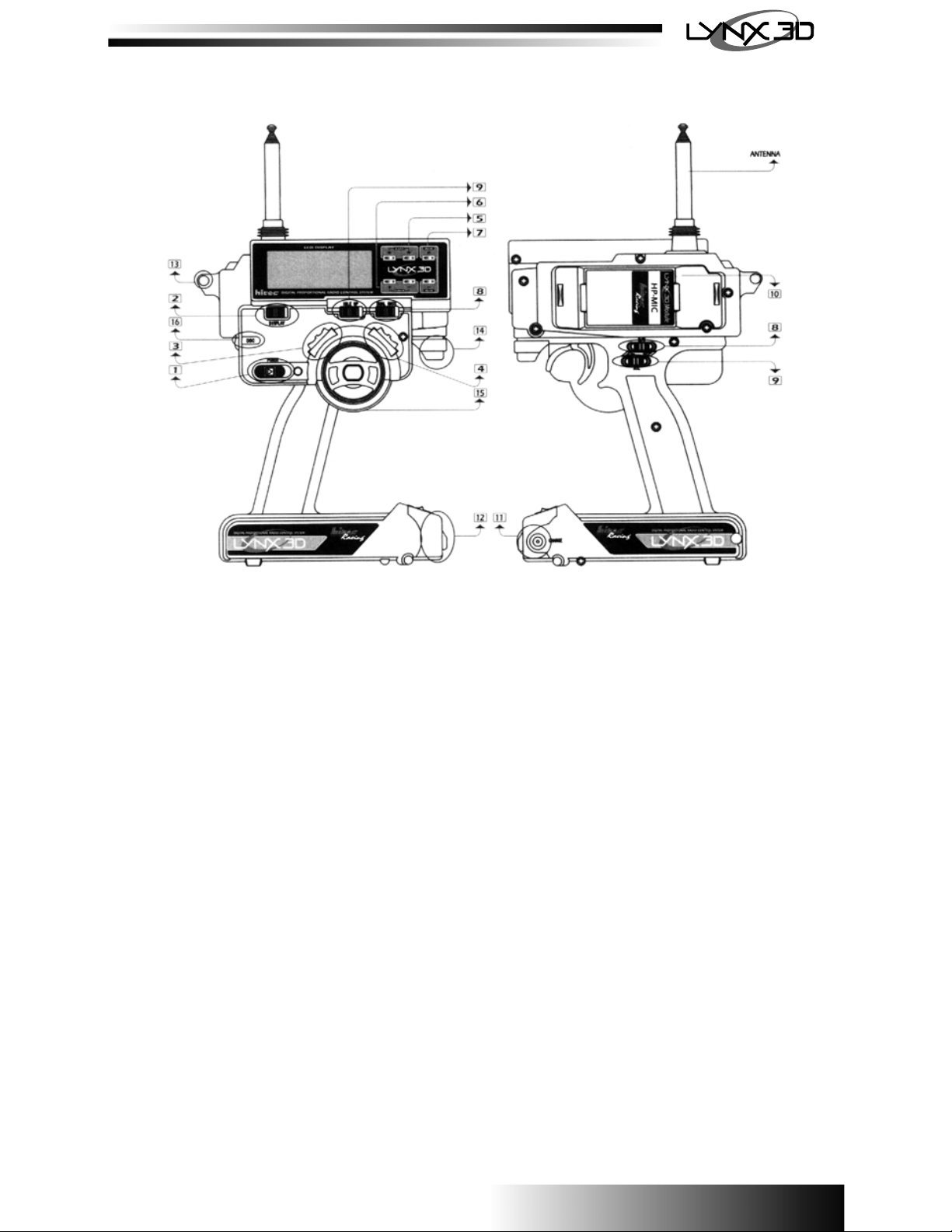
External Switches and Their Usage
1. Power switch: Powers the system
2. Display switch: Allows programming without powering the RF signal.
3. Idle up switch: Used with gas or nitro vehicles to increase the idle speed at engine start up.
Switch position right is “ON”.
4. Dual rate switch: Selects between *auto dual rate (left) and standard dual rate (right).
5. Throttle trim: Adjusts the neutral point of the throttle and brakes.
6. Steering trim: Adjusts the neutral point for the steering.
Programming Buttons for LCD Screen
7. Edit up/down: Accesses the menu when pushed simultaneously and is used in scrolling through
the menu to select the area to program.
8. Data inc/dec: Adjusts setting when accessing the menu.
9. Aux +/-: Used for CH. 3 and changing data in selected menus.
Handle Switches
10. Dual Rate Adjust: Selects the amount of travel the steering servo will turn.
11. ATL: Used to adjust the maximum amount of braking that will be applied when the brakes are
fully engaged. Note: This is also the EPA (End Point Adjustment) for the brakes.
Physical Features
1. Removable transmitter frequency module.
2. External charging jack: Port for charging NiCads with the supplied “overnight” charger.
3. Battery door: Access to the transmitter NiCad battery box.
4. Wrist strap mount: For connecting optional wrist or neck strap, part # 58311.
5. Brake depth adjustment screw: Limit the amount of physical brake lever travel.
6. Wheel tension adjustment screw: Increases or decreases the steering wheel tension.
7. D.S.C. (Direct Servo Control): Controls the receiver directly via the DSC Cable.
8. Right/Left hand operation: Transmitter head can be adjusted for right or left hand use.
1
Page 3
Electronic Features
The following features are described in depth throughout this manual
− 3 Channel FM digital proportional system
− 10 model memory
− Model copy
− End Point Adjustment (EPA)
− Exponential (Steering and Throttle curve)
− Digital Dual Rate (Two modes)
1. Standard
2. Auto (Dual settings per throttle position)
− ATL Brake (Adjustable Travel Limit)
− ABS Brakes (Anti-lock Braking System)
− Idle up
− Timer (Up/Down) with audible alarm
− Five position programmable 3rd channel
− Digital trims
− Audible low battery warning
− Auto Save (Warning: Auto save must engage before programming can continue or data may
be lost. This is done by allowing the EPA settings to “Auto Save” by letting the voltage
reappear on the screen before proceeding with any other adjustments, this takes
approximately 2 seconds).
2
Page 4
DCX Receiver:
Included in the Lynx 3D system is the most advanced surface use receiver on the market today. The
Hitec DCX receiver features dual conversion technology that filters the transmitter’s signal twice,
decreasing the chance of stray RF “noise” causing interference. This “dual conversion” feature
produces the best performance possible in even the most demanding conditions.
Note: When used with and ESC (Electronic Speed Control) the receiver is powered by the ESC
through the throttle channel. When used in a vehicle without an ESC, such as gas or glow engine,
the receiver must be powered with an external 4.8V - 6.0V battery pack that is plugged into the Bat/
DSC channel.
Channel assignments on the DCX receiver:
CH1: Steering
CH2: Throttle
CH3: Auxiliary
Bat/DSC: Battery and DSC (direct Servo Control)
HFS-03MC Receiver:
Included with the Lynx 3D (Some Non U.S. version only) is the 03MC single conversion receiver. The
03MC is the best performing single conversion receiver available today and is also available separately as a lower cost alternative to the DCX.
Note: When used with an ESC (Electronic Speed Control) the receiver is powered by the ESC
through the throttle channel. When used in a vehicle without and ESC, such as a gas or glow engine
vehicle, the receiver must be powered with an external 4.8V - 6.0V battery pack that is plugged into
the Bat/DSC channel.
Changing Frequencies:
When using the system in competition environment it may be necessary to change the systems
operating frequency.
Receiver:
Receiver crystals can be changed within the entire band with no loss of performance. Use only
genuine Hitec Dual Conversion receiver crystals in the DCX receiver and only genuine Hitec Single
Conversion crystal in the HFS-03MC receiver.
Transmitter:
The Lynx 3D is equipped with a frequency module and has a crystal plugged into it. You can change
between the 27MHz and 75MHz bands by changing the entire module. To change channels in the
transmitter within the band, it is recommended you replace the entire module tuned to a specific
frequency for maximum performance. However the crystals may be replaced in the module but it will
reduce the performance slightly. Use only genuine Hitec crystals.
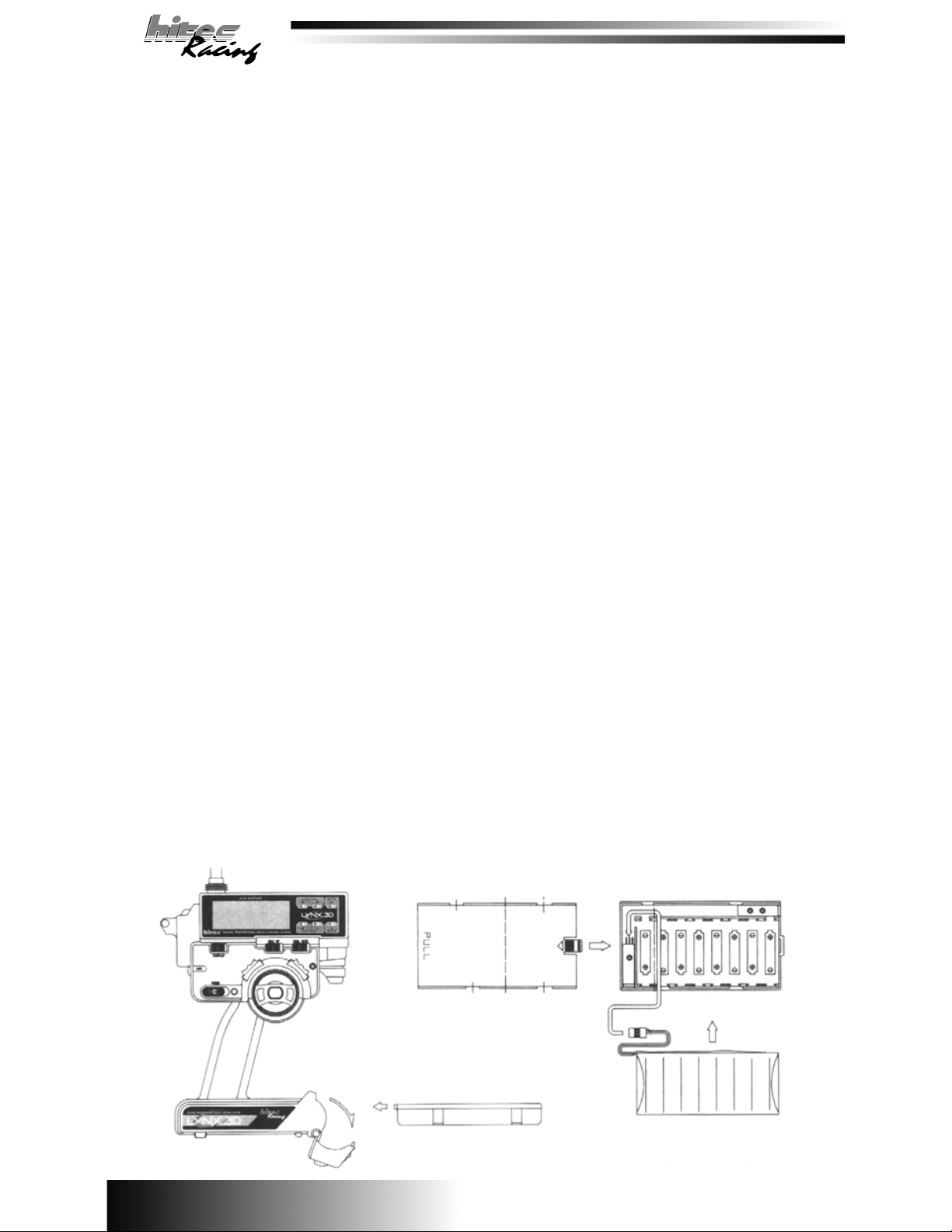
Transmitter NiCads and Battery Charging:
The Lynx 3D comes equipped with NiCad batteries in the transmitter and an “overnight” charger for
your convenience. To charge the batteries simply connect the charger to the charging port in the
transmitter case or in the battery box. This can be done while he batteries are in or out of the
transmitter. Normal charging time is approximately 12-18 hours. Caution: Batteries should not be
left on charge for longer than 24 hours.
3
Page 5
Fast Charging TX Battery:
Although Not recommend for normal charging, it may become necessary to fast charge the transmitter battery if it becomes drained or you neglect to charge them overnight. This can be done with a
peak charger but the battery must be removed from the battery box and connected directly to the
charger. This is done by using a female “S” connector # 57343s. It is recommended the charge rate
not exceed 1.5 Amps for a quick charge.
Dry Cell Version:
Some versions of the Lynx 3D may not include NiCads and you will be required to use AA Alkaline
batteries. Place the batteries in the battery holder paying close attention to the polarity. Once the
batteries are installed properly the battery holder may be placed back in the transmitter for use.
(Warning: Do not attempt to recharge Alkaline batteries, they will explode).
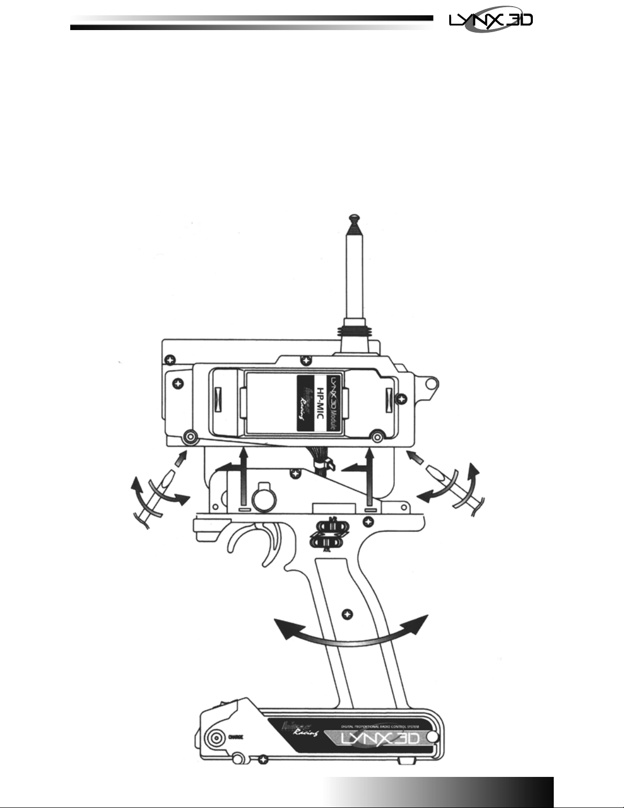
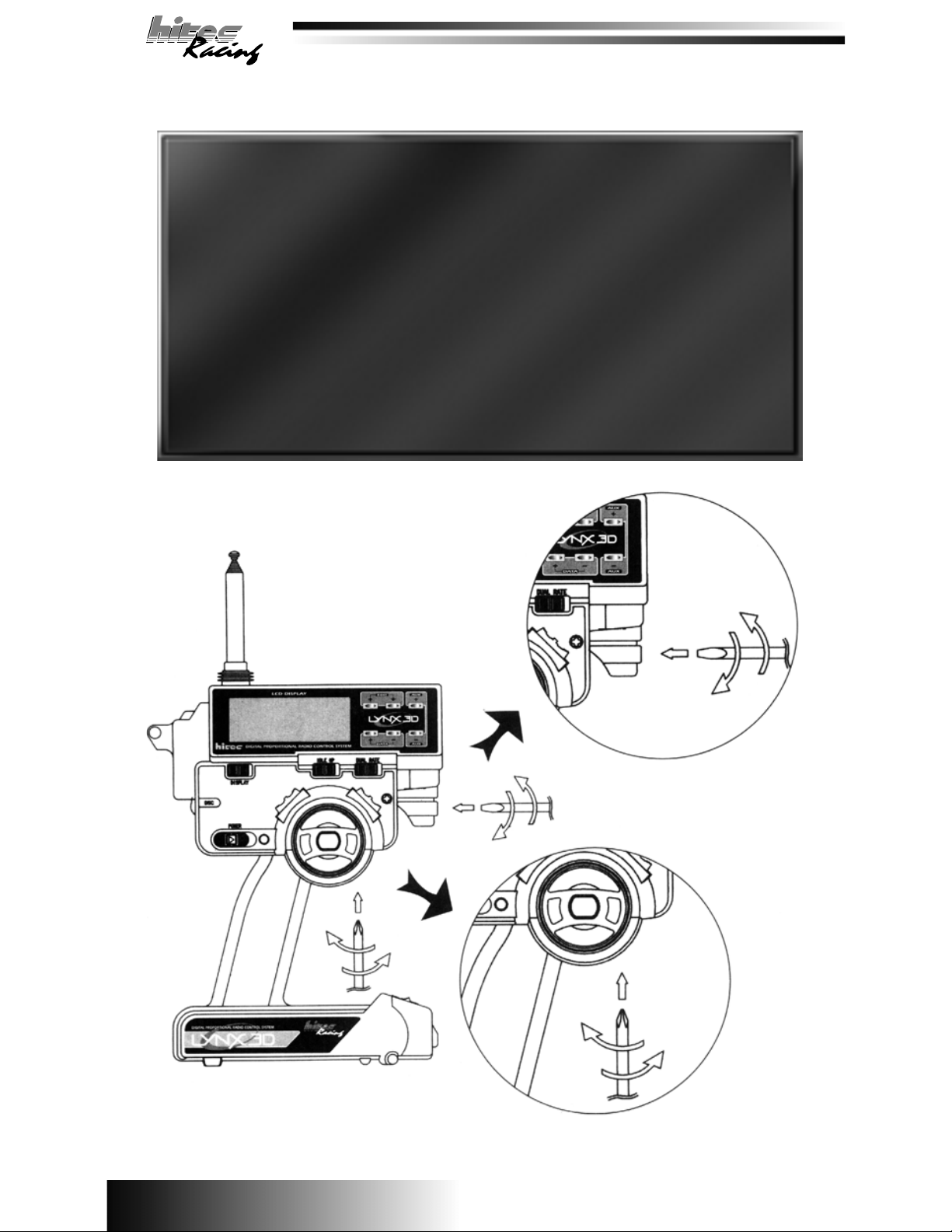
Left Handed Operation:
The Lynx 3D is capable of converting from right to left handed operation. To do so please refer to the
diagram below.
4
Page 6

Now that you have familiarized yourself with the features and functions of the Lynx 3D, let’s
discuss how to program them. Below is a reference of how the editing menu is laid out.
STEERING EPA
THROTTLE EPA
-10 0
+10 0
MODEL RESET
MODEL COPY
MODEL SELECT
TIMER
EPA
%
1
CHANNEL CHANNEL
EPA
%
2
CHANNEL
2
RL
RST
COPY
MODEL
+10 0
-10 0
%
%
CHANNEL
12
MODEL
2
SL
TIMER
0
:0
EPA
1
EPA
2
ABS
OFF
ABS
SERVO REVERSE
IDLE UP
POINT
OFF
AUX CH3
NOR
EXPONENTIAL
AUTO D/R
%
2
10
ID-UP
CHANNEL
%%
0
ABS
DLY
OFF
+10 0
3
CHANNEL
NOR
AUTO D/R
2
ABS
AUX
%
1
1
CHANNEL
EXP
%%
1
10
CHANNEL
POINT
%
1
10
SPD
OFF
REV
-10
2
ABS ABS
2
CHANNEL
EXP
2
CHANNEL
OFF
10 0
D
5
Page 7

Edit Menu Access:
To access the edit menu, turn the display or power switch on, while pushing the “Edit” up/down keys
simultaneously. Once you are in the edit menu use the up or down buttons to scroll through the
options. To exit the edit menu, push the “Edit” up/down keys simultaneously. The battery voltage will
appear with the model number you are currently using. By using the down key the options will appear
in the following order.
DATA : 0--+/-125%
RESET
RL X
EPA
ABS
CHANNEL
EDIT
-
DEFAULT : 100%
XXX X
$
AUTO D/R
EDIT
EPA
POINT
%%
1
AUX
CHANNEL
+
EPA
BLINKING
XXX
AUTO D/R
%
AUX
CHANNEL
+
1
BLINKING
EPA
AUX
+
$
10 0
%
$
10 0
2
CHANNEL
This is the servo end point adjustment for right and left steering, throttle and brakes. To select
between channels 1 (Steering) and 2 (Throttle) us the Aux. +/- keys. You can adjust the (+) side as
well as the (-) side. To select between the two you must move the steering wheel or trigger slightly
until you see the (+/-) symbol change, then adjust as needed. To reset back to the factory default
press the “Data” inc/dec buttons simultaneously. Note: (-) ch 2 is also affected by the ATL on the
handle. (Important: Always allow the EPA settings to “Auto Save” by letting the voltage reappear on
the screen before proceeding with any other adjustments. This takes approximately 2 seconds).
Racer Tip
Steering:
With the wheels trimmed at neutral set the D/R steering to max (125%), next use the EPA
setting to adjust the wheels to maximum right and left without binding the servo. For
maximum steering set the EPA a couple of % points higher once the servo hits the stop.
This will give you maximum steering.
Throttle:
The EPA setting is used primarily with gas or nitro vehicles. Pull the trigger and adjust the
EPA so the throttle servo opens the barrel of the carburetor to maximum without binding.
The brake setting is a little different, remember the ATL adjustment on the handle can
adjust the amount of brakes, so the best thing to do is set the EPA at maximum (125%) so
the brake does not bind and lock up when applied. Then use the ATL (same setting as the
EPA) to fine tune the amount of brake you wish to have when the brake lever is pushed
out.
*For an electric vehicle with ESC, you should not need to adjust the “+” setting, it is all
done when setting up the ESC. The ATL can still be used to adjust the maximum braking.
Set to 125% when setting up the ESC.
6
Page 8

Model Reset:
This feature will allow you to reset any model back to the factory default setting. You must select the
model to be reset in the model select “SL” screen. Once you have selected the proper model, push
the “Data” inc/dec keys simultaneously, there will be an audible “beep” to verify reset.
COPY
COPY
MODEL
EDIT
XX
Model Copy:
This feature allows you to copy a pre-exiting program to another model number. The model you wish
to copy “From” must be selected in the model select “SL” screen. Then using the “Aux.” +/- keys, you
can select the model you wish to copy “To”. Once you have selected the proper models push the
“Data” inc/dec keys simultaneously and there will be an audible “beep” to verify copy.
MODEL SELECT COPY
MODEL
EDIT
SL X
RST EPA
RL X
RST
MODEL
COPY
XX
EDIT
$XX X X
DATA : 0 - 9
BLINKING
EDIT
RL X
MASTER
SLAVE DATA : 0 - 9
EPA
%
CHANNEL
RST
RST
Model Select:
This feature associates a number to the model. The letters “SL” will appear on the screen with a
blinking number 0 - 9. These are your model numbers; they can be adjusted by using the “Aux.”
+/- keys to select the model you wish to program and use.
Racer Tip
To help remember which model is which number, use a little round sticky dot you can buy
at most stationary stores. Mark the model number and stick it on top of the receiver.
TIMER
TIMMER
XX:X X
EDIT
MODEL SELECT
MODEL
SL X
EDIT
MODEL COPY
COPY
XX
DATA : 0 - 9 SELECT : CHANNEL KEY
BLINKING
MODEL
7
Page 9

Timer:
The timer can be selected to count up or down. Leave the setting at zero if you wish to count up. To
count down, select the amount of time you wish from 1 - 60 minutes using the “Data” key inc/dec
buttons. Once you have selected the time, it can be activated by pressing the “Edit” DN key after you
are out of the programming menu.
Racer Tip
You can use the timer two ways, to count up or count down. If you want to see how long
your car will run, use the count up setting. If you are looking to simulate race conditions,
set it to count down, normally 4 or 5 minutes. There will be an audible tone each minute
and a countdown for the last 10 seconds. This way you can tell how the car feels at the
end of a simulated race and see if you have the proper gearing. If your car has slowed
substantially, before or at the end of the countdown, gear down a tooth or two on the
motor pinion.
IDLE-UP TIMER MODEL SELECT
XX 2 SL X00:0
ID-UP
BLINKING
EDIT
TIMER
EDIT
0
DATA : 0 - 60MINUTE
DEFAULT : 00
TIMER VALUE NOT SETTING : UP COUNTER
TIMER VALUE SETTING : DOWN COUNTER
MODEL
Idle Up:
This feature is typically used with gas and/or nitro powered cars or boats. Primarily at start up when
the engine is cold. By using the throttle trim with the idle up switch selected to the right, you can
select from a 0 - 50% throttle increase.
Racer Tip
The idle-up is used primarily with gas or nitro powered vehicles. Start off at 10% and
adjust from there. The purpose is to keep a cold engine running, similar to a choke in a
real car. Keep is on for about a minute, or until the engine is warmed up. Note: The
idle-up can also be used as the primary throttle trim and will not affect the end points like
the standard trim. Use this only if you are continually adjusting the drag brake on your
vehicle.
POINT
ON
XX X 0
EDIT
ABS
%
2
ID-UP
DATA : 0 - 50%
DEFAULT : 0%
KEY : DATA DEC/INC
CHANNEL
BLINKING
8
EDIT
TIMERIDLE-UPA.B.S.
TIMER
00:0
0
Page 10

ABS: (Anti-Lock Braking System)
This feature is advantageous in applications where hard, late braking is required. First you must
select the point you want the ABS system to override the standard braking. Move the brake lever to
the desired position and push the “Data” inc/dec keys simultaneously. Next use the “Aux” +/- keys to
scroll through the ABS menu. Push the (-) key to access the screen to turn the ABS feature on or off.
Press the “Data” inc/dec keys simultaneously to turn it on and off. Next you will need to select the
braking depth. There will be a small “d” flashing with a %, you can select from 0 - 100% by using the
“Data inc/dec keys. This selects how much movement there is when the servo is pulsating from the
ABS. Next you will need to select the “SPd” or the “speed” of the pulse by using the “Data” inc/dec
keys, 0 is the fastest and 9 is the slowest. Now use the “Data” inc/dec keys to select the “dly” or
“delay”, this is adjustable from 0 - 9, nine being the longest until the ABS engages.
Racer Tip
ABS is used primarily with gas vehicles but can be used for electric’s as well. A good
place to start is by setting the depth to 50% and the speed and delay to “5”. Experiment
with it to find the optimum setting for your particular application
CH3 IDLE-UP
%
$XXX X
AUX
DATA : 0 - 99
DEFAULT : 0
EDIT
EDIT
BLINKING
POINT
%
-
AUX
-
AUX
AUX
%
AUX
BLINKING
+
0
BLINKING
+
0
+
d
+
ABS
DATA : 0 - 9
DEFAULT : 0
ABS
DATA : 0 - 9
DEFAULT : 0
ABS
DATA : 0 - 100%
DEFAULT : 0
BLINKING
DEPTH
ABS
DATA
ABS
PUSH TOGETHER
+ / -
00
dl y
-
AUX
sp d
+
xx x
BLINKING BLINKING
POINT
ON
%
2
ID-UP
POINT
OFF
ABS
9
Page 11

Auxiliary Channel 3:
This is the third channel of your three channel radio and can be used for many different applications.
There are 5 programmable settings for the Aux. 3rd channel. They can be selected by pressing the
Aux. +/- keys to access each point. Once you have selected the #, they can be adjusted by using the
“Data” in/dec keys. Continue with all 5 until they are programmed to your needs. If you wish to use
less than the five setting you can inhibit #2, 3 or 4 by pressing the “Data” inc/dec keys simultaneously,
the screen will read “Inh”. To reactivate the inhibited setting just push the “Data” inc/dec keys
simultaneously and select the %. To activate the third channel once it is programmed, push the “Aux”
+ or - keys to cycle through the points you have programmed.
Racer Tip
The most common use of this function is the manipulation of a remote needle valve
adjustment for nitro boats. Lets talk about how to set it up. First, you want to determine
the neutral position and set this on #3. This will allow you two clicks up and two clicks
down. Next, program the settings so you can “learn” or :richen” the motor for fine tuning
the performance. Do not have drastic changes: a few percentage points are fine.
Experiment for yourself to find the optimum.
REVERSE A.B.S.
EDIT
%
NO R
X
CHANNEL
$XX XX
+
AUX
%
-100
+
AUX
1N H
-
AUX
+
AUX
+
%
0
+
AUX
1N H
-
AUX
EDIT
AUX
AUX
1
AUX
22
AUX
333
4
+
$XXX X
DATA
+ / -
$XXX
DATA
+ / -
-50
PUSH
TOGETHER
DATA
+ / -
TOGETHER
DATA
+ / -
TOGETHER
1N H
PUSH
+50
PUSH
DATA : 0 -- +/-100%
%
%
1
%
%
4
DEFAULT : 1- -100%
DEFAULT : 2- INH
ABS
DEFAULT : 3- 0%
DEFAULT : 4- INH
DEFAULT : 5- +100%
AUX
AUX
DATA
+ / -
AUX
DATA
+ / -
AUX AUXAUX
DATA
+ / -
$XXX
$XXX
$XXX
%
AUX
2
%
AUX
%
4
%
5
+100
AUX AUX
%
5
DATA
$XXX
+ / -
Servo Reversing:
This is used to change the rotating direction of your servos. Use the “Aux” +/- keys to select channel
#1 (Steering), #2 (Throttle) or #3 (Aux). Normal rotation will look like “noR” and reverse will look like
“REv”. To change these settings you will have to push the “Data” inc/dec key simultaneously.
10
Page 12

EXP
EDIT
EXP
%
$XXX X $XXX X
CHANNEL
REV CH3
EDIT
NO R X
CHANNEL
+
AUX
%
AUX
-
AUX
+
NO R
NO R
NO R
1
CHANNEL
+
AUX
2
CHANNEL
+
AUX
33
CHANNEL
DATA
+ / -
PUSH TOGETHER
DATA
+ / -
PUSH TOGETHER
DATA
+ / -
PUSH TOGETHER
RE V
RE V
RE V
1
CHANNEL
2
CHANNEL
CHANNEL
Expotential:
This feature is used to change the control travel from linear to nonlinear. Us the “Aux” +/- keys to
select channel #1 (Steering or #2 (Throttle), the use the “Data” inc/dec to select positive (+) or
negative (-) Expo. Positive Expo increases the sensitivity and negative Expo decreases it. To reset
back to the default, press the “Data” inc/dec buttons simultaneously.
Racer Tip
A very valuable feature, exponential allows you to change the servos travel from
proportional to non-proportional. Negative Expo desensitizes the initial movement and
positive Expo increase the sensitivity. So why should you use it? It all depends on your
driving style. Here a few ideas for why and when to use it.
Steering:
Negative Expo is most commonly used for steering. This makes the vehicle much less “twitchy” and easier to control
down the straight aways. A good starting point is -30%. Remember you will still get all the travel. If you were to use “+”
Expo the wheels would move more for the same amount of steering input. This tends to make the car very sensitive and
will you will tend to oversteer. Try changing these settings for yourself to see how it reacts to the different input.
Throttle:
A good rule of thumb is to use negative Expo for modified motors. This gives a broader power band a positive Expo with
stock mores for more punch. Another factor is the track conditions. Use negative for loose conditions and positive for
high traction. Again, experimenting will give you and idea what works best for your particular application and driving
style.
AUTO D/R
POINT
XX X $XX X X
AUTO D/R
%%
1
DATA : 0 -- +/-125%
DEFAULT : 0%
EDIT
-
AUX
+
0
0
11
AUX
%
AUX
%
CHANNEL
+
1
CHANNEL
-
+
2
CHANNEL
EXP
EXP
EXP
BLINKING
EDIT
BLINKING
BLINKING
REV
NO R X
CHANNEL
Page 13

Auto Dual Rate:
This feature allows you to select individual high and low speed steering travel. First you must set the
throttle position where the rate will switch from #1 to #2. This is done by pulling the trigger to the
desired position and pushing the “Data” inc/dec buttons simultaneously. A “%” will show up on the
screen, this is the throttle % where the rate will change from #1 to #2, at this point, if you wish to
change it repeat the procedure again. Next, select the travel you wish to associate with the #1 and
#2 settings. This is done agter you exit the set up menu. Select the dual rate slide switch to the left,
adjust the #1 setting then pull the trigger until the #2 appears. You will use this feature to gain more
high or low speed steering according to throttle position. Important: Always allow the D/R setting to
“Auto Save” by letting the voltage re-appear on the screen before proceeding with any other
adjustments, this takes approximately 2 seconds.
Racer Tip
Auto D/R
Unique to the Lynx 3D, Auto Dual Rate can be a big advantage when you need to have more high speed
steering than low speed or vice versa. Let’s say your car is understeering (Pushing) under power but
oversteering (Loose) when you let off the throttle entering the corner. With the Auto D/R setting you can
select two different rates that will change at the programmable throttle position you select (refer to the
programming instructions on how to select settings). You would then select the #1 position to have
reduced travel and the #2 position to have more. Swap the settings on #1 and #2 for a car that oversteers
at high speed and understeers at low speed.
Standard Dual Rate
A must have for any race, this feature is adjusted from the digital switch marked D/R on the handle. To
distinguish from Auto D/R to standard D/R the dual rate switch on the front of the transmitter must be
selected to the right, it will read #3 on the display screen when accessed. Use the dual rates to fine tune
the handling of the vehicle by increasing or decreasing steering servo travel. If the vehicle is oversteering
(Loose) pull back on the switch to decrease the steering. If it is understeering (Pushing) increase the
steering by pushing the switch forward. The percentage of steering will automatically pop up on the LCD
screen. You can bump it one percentage point at a time fro fine tuning or hold it down for a more drastic
change. Continue to adjust this setting until the vehicle is more controllable and handling the way you
want.
EPA
EDIT
EPA POINT
%%
$XX X XX X $XX X X
1
CHANNEL
POINT : 0 -- 100%
BLINKING
POINT
AUTO D/R
BLINKING
POINT
XX X
AUTO D/R
BLINKING
POINT
AUTO D/R
DATA 1 DATA 2
SETTING POINT LOW : DATA 1
SETTING POINT HI : DATA 2
NOT SETTING POINT : DATA 1
POINT
1
%
1
0
CH2 STICK SELECT
-
(DEC/INC PUSH TOGETHER)
+
AUX
%
2
%
1
0
EDIT
EXP
%
12
EXP
Page 14
This concludes the programming portion of the set up. Below are a few more tips on the Lynx 3D
features that can improve you driving skills.
Racer Tip
Steering
Make sure you have the steering trim at or very close to 0% when the horn and wheels are straight. If
you change the neutral point too far from center you should reposition the servo horn to center. If trims
and horn are centered and the steering is still off, adjust the linkage to compensate.
Throttle
The trims are a valuable tuning tool and can be adjusted to change the vehicles handling. (-) trim will
add more “drag brake” when the trigger is released. This will give the vehicle more steering entering
the corner. Too much “drag brake” will cause the vehicle to overteer and slow the corner speed. (+)
trim will actually allow the car to creep forward when the throttle is released so you would have to hold
the brakes to keep it from moving when stopped. This will give the car less steering when entering a
corner but also helps keep the corner speed up. You may have to increase your steering travel to
allow you to use this set-up. It can be the hot ticket for touring cars to achieve maximum corner speed!
As always test these adjustment yourself for you particular application to see how the affect your
vehicle to find the optimum settings. Important: Always allow the trim settings to “Auto Save” by
letting the voltage reappear on the screen before proceeding with any other adjustments, this take
approximately 2 seconds.
Brake Depth Adjustment:
This feature adjusts the physical limit
the throttle trigger moves in providing
the forward and reverse/brake function. It is adjusted by the screw on the
outside of the radio opposite the
trigger.
Wheel Tension Adjustment:
This feature adjusts the steering wheel tension. The tension is set in
the middle from the factory so it can be increased or decreased as
desired.
13
Page 15

D.S.C. (Direct Servo Control)
This feature allows the operation of the receiver without transmitting a signal. Connect the DSC cord
to the transmitter by plugging it into the jack on the left side of the transmitter face. Note: The
transmitter will turn on automatically but will not be transmitting a signal. Then connect the other end
of the cord to the receiver in the Bat/DSC slot if used in conjunction with an ESC or to the external slot
on the optional switch harness if used with a NiCad receiver battery.
Driving Tips:
1. One of the most common problems with new racers is that they feel the have to “race” everyone
on the track, every turn. Try to focus on your car and your lines only, don’t worry about the other
guys. “Slower is faster!” Don’t over drive the track, slow down and set up for each corner early.
2. Don’t try to hit full throttle out of every turn and hold it as long as possible. This makes you go
slower. Try to be smooth and roll on and off the throttle, don’t just “yank” it!
3. Stay off the boards. Take a conservative line at least a foot away. Slow down and get a few
“clean” laps in and your lap times will be faster!
4. Once you are consistent and not crashing, you can start taking a tighter line and getting on the
throttle sooner and braking later to improve your lap times. It’s all about timing!
5. Remember one important thing about racing; “You must first finish to finish first!’
Final Thoughts:
Many years of experience and research have hone into the development of the Lynx 3D and we are
confident it will help you improve your driving. You need to realize the radio is used for “Fine” tuning
and will overcome some problems associated with the cars handling, but a proper set up on the
vehicle first will make going fast a whole lot easier!
14
Page 16

A new dimension of control
 Loading...