

Page 1

7 Channel 2.4 GHz Aircraft Computer Radio System
7 Channel 2.4 GHz Aircraft Computer Radio System
7 Channel 2.4 GHz Aircraft Computer Radio System
OPERATION MANUAL ver. 1.0
Page 2
7 Channel 2.4 GHz Aircraft Computer Radio System
7 Channel 2.4 GHz Aircraft Computer Radio System
Warning
Note
TipTip
Tip
Caution
Warning
Note
TipTip
Tip
Caution
Before Using
Before using your transmitter, it is recommended that you read this manual in its entirety to become
familiar with the product and its features. Failure to operate this product properly can result in damage to
property and or cause serious injury.
Important Notices
Please note that Hitec reserves the right to make production changes during the life of our product lines
that may impact the information in this manual. For the most up-to-date information on this and any
other Hitec product, visit our web site at www.hitecrcd.com.
This product was designed and intended for use with hobby models designed specically for
radio control only. Hitec RCD disclaims all liability for any damages or injuries resulting from the
use of this product for anything other than its intended purpose.
This radio control transmitter is not intended for use by children under 14 years of age. Adult
supervision is required for any user under the age of 14.
DISPOSAL OF eWASTE
This symbol indicates that when this type of electronic device reaches the end of its service life, it cannot
be disposed of with normal household waste and must be recycled. To nd a recycling center near you,
refer to the internet or your local phone directory for electronic waste recycling centers.
STATE OF CALIFORNIA PROPOSITION 65 WARNING:
This product contains chemicals known to the State of California to cause cancer. Use caution when handling this product and avoid exposure to any electronic components or internal assemblies.
Regulatory information
Hitec RCD Inc.
Radio Control Hobby Model Controller
Model Name: Flash 7
Operating Frequency: 2.4GHz
Power
Charger: None
Transmitter: 6.0V (4AA Alkaline Batteries)
This device complies with part 15 of the FCC Rules. Operation is subject to the following two conditions:
1. This device may not cause harmful interference.
2. This device must accept any interference received, including interference that may cause undesired
operation.
Section 1: Introduction
1
Page 3
7 Channel 2.4 GHz Aircraft Computer Radio System
Table of Contents
7 Channel 2.4 GHz Aircraft Computer Radio System
Introduction
Safety Information........................................................................................................................6
Product Support............................................................................................................................7
Steps for Successfully Programming the Flash 7 Radio...................................................8
System Component Specications.........................................................................................9
Terms and Icons...........................................................................................................................10
Powering the Flash 7..................................................................................................................11
Transmitter Controls...................................................................................................................11
Main Menu.....................................................................................................................................12
Transmitter Warnings.................................................................................................................12
Maxima Series Receivers..........................................................................................................13
Optima and Minima Receivers...............................................................................................15
Fail Safe and Hold Mode Setup..............................................................................................19
Telemetry System........................................................................................................................20
Range Check Function...............................................................................................................21
Scan Mode Function..................................................................................................................22
SLT System.....................................................................................................................................23
Quick Start Guides
Airplane Quick Start Guide.......................................................................................................24
Helicopter Quick Start Guide...................................................................................................26
System Menu Programming
System Menu.................................................................................................................................28
Model Select Menu.....................................................................................................................29
Model Type Menu .......................................................................................................................32
Model Type ACRO Menu Programming...............................................................................32
Model Type GLID Menu Programming.................................................................................33
Model Type HELI Menu Programming.................................................................................35
Channel Selection Menu...........................................................................................................36
Trim Step.........................................................................................................................................37
Trainer Function...........................................................................................................................37
Control Modes..............................................................................................................................40
Management Menu....................................................................................................................40
2
Section 1: Introduction
Page 4
7 Channel 2.4 GHz Aircraft Computer Radio System
7 Channel 2.4 GHz Aircraft Computer Radio System
Table of Contents
Common Model Programming Menu
Working with the Common Model Function Menus...................................43
Servo Reverse....................................................................................................44
Sub Trims............................................................................................................44
Dual Rates and Exponentials..........................................................................45
Switch Assignment...........................................................................................47
End Point Adjustments ...................................................................................47
Servo Speed ......................................................................................................48
Programmable Mixes .......................................................................................48
Timers..................................................................................................................51
Servo Monitors..................................................................................................54
Throttle Lock......................................................................................................55
ACRO and Glider Programming
Acro and Glider Programming Menu.............................................................56
Flight Conditions...............................................................................................57
Aileron Differentials..........................................................................................58
Elevon Mixing....................................................................................................59
V-Tail Mixing.......................................................................................................60
Ailevator Mixing................................................................................................62
Aileron to Rudder Mixing................................................................................63
Elevator to Camber Mixing..............................................................................65
Camber Mixing (GLID Only).............................................................................68
Flap Control........................................................................................................70
Offset...................................................................................................................71
Butterfly Mixing (GLID Only)...........................................................................72
Gyro.....................................................................................................................75
Throttle Cut (ACRO Only).................................................................................76
Throttle Curve....................................................................................................78
Section 1: Introduction
3
Page 5
7 Channel 2.4 GHz Aircraft Computer Radio System
Table of Contents
7 Channel 2.4 GHz Aircraft Computer Radio System
Helicopter Programming
Helicopter Programming Menu.....................................................................80
Flight Conditions..............................................................................................80
Throttle Cut.......................................................................................................82
Throttle Hold.....................................................................................................83
Gyro.....................................................................................................................84
Revolution Mixing............................................................................................86
Swash to Throttle Mixing................................................................................88
Swash Mixing....................................................................................................90
Throttle Curve...................................................................................................91
Pitch Curve........................................................................................................93
Swash Ring........................................................................................................95
Using the Telemetry System
Working with the Sensor Menu......................................................................96
GPS.......................................................................................................................96
RPM......................................................................................................................97
Temperature.......................................................................................................98
Battery.................................................................................................................98
Servo Manager...................................................................................................99
Advanced Telemetry Sensors..........................................................................99
Viewing Telemetry Data.................................................................................100
Hardware Adjustments
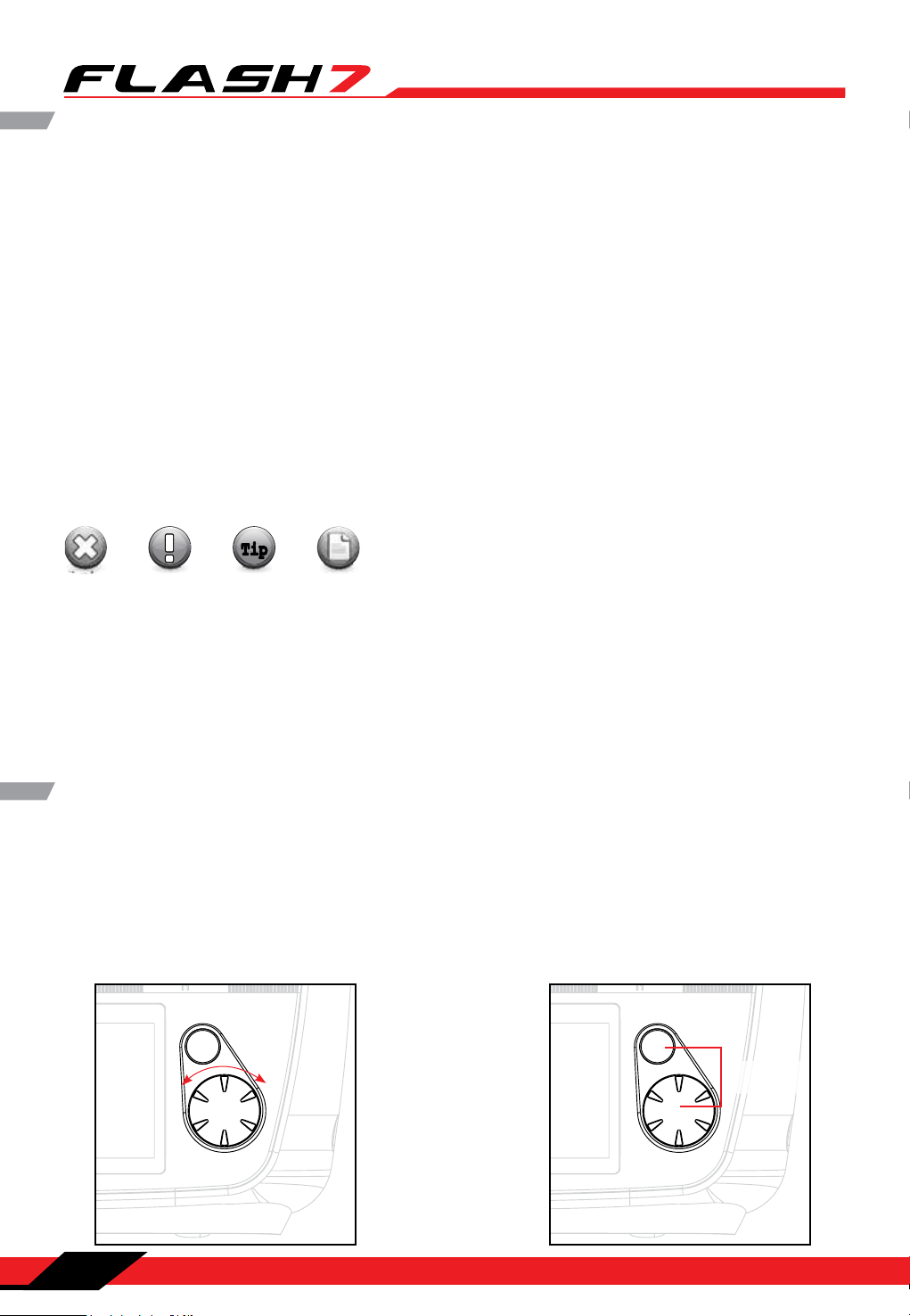
Stick Length Adjustments..............................................................................101
Stick Lever Tension Adjustment / Mode Change.......................................101
4
Section 1: Introduction
Page 6

7 Channel 2.4 GHz Aircraft Computer Radio System
7 Channel 2.4 GHz Aircraft Computer Radio System
Introduction
Thank you for purchasing the Flash 7 radio by Hitec. Designed for all popular aircraft types, the Flash 7
delivers lightning fast response with its 7ms frame rate and 4096 step resolution. You can trust Hitec’s
bi-directional, AFHSS (Advanced Frequency Hopping Spread Spectrum) 2.4GHz technology to guide your
sailplane, gas, glow or electric power plane or heli to a safe landing every ight. We are sure you will nd
the Flash 7 one of the easiest radios to program. Please review this entire manual to learn how to safely
use your new radio. It’s a good idea to keep the manual with your Flash 7 at all times.
Features
1. Triple Protocol 2.4GHz Transmitter: The Flash 7 can transmit using three dierent 2.4GHz signals.
a. Our original AFHSS bi-directional telemetric 2.4Ghz signal used with the Minima and Optima
series receivers.
b. Our Low Latency G2 AFHSS 2.4GHz signal used with Maxima series receivers.
c. The SLT™ protocol found in many Tx-Ready aircraft. For more info visit www.Tx-Ready.com.
2. 3 in 1 Radio: With advanced Acro, Glider and Helicopter programming you have the ability to advance
your ying skills without having to upgrade your radio.
3. Precise 4096 Resolution: At two to four times the resolution of most transmitters, the Flash 7’s 4096
step resolution gives you more precise and crisp servo movement.
4. Backlit Graphical LCD screen: Makes it easy to see the programming and telemetry displays.
5. Push Button / Jog Dial Programming Interface: So that programming the Flash 7 is a breeze.
6. 2 Virtual Master Channels for Mixing: Allows for advanced mixing found only in radios with more
channels.
7. 6 Assignable Switches and 2 Sliders: Gives you plenty of choices for total control.
8. Telemetry Capabilities with our Optima Receiver: Keeps you informed of what’s going on in your
plane.
9. DCS Port (Battery Voltage Power Out): Powers optional accessories such as VR goggles or head
tracking units.
Section 1: Introduction
5
Page 7

7 Channel 2.4 GHz Aircraft Computer Radio System
7 Channel 2.4 GHz Aircraft Computer Radio System
Safety Information
Flying models can be dangerous if proper safety precautions are not followed. Here are a few critical
safety suggestions to keep you and others safe.
Are you experienced?
Flying models is not an intuitive process. Most accomplished model pilots were taught by another
modeler. We encourage you to seek help during your early ight experiences and if required, during
the building and radio gear installation process. Unlike some other hobbies, model airplane ying has
evolved into a social event. There are approximately 2,500 model aircraft clubs in America. Friendship and
help could be right around the corner. Ask your local hobby shop about clubs in your area.
Where to Fly
Having enough land for your own model airport is rare. Most of us y at club administrated model elds.
The local ball eld can be tempting but rarely has the space needed and your liability is high should you
damage property or hurt an innocent bystander. We recommend you y at a sanctioned model aircraft
eld.
Join the AMA
In America, the Academy of Model Aeronautics (AMA) is an organization of model enthusiasts that
provides resources and insurance to modelers. The AMA also lobbies the Government concerning
legislation that impacts modelers. Visit their web site for more information at www.modelaircraft.org.
Academy of Model Aeronautics
5151 East Memorial Drive
Muncie, Indiana 47302
Toll Free: 800 435-9262
Fundamental Guidelines for Safe Flying
1. Model aircraft can be dangerous when operated or maintained improperly.
2. DO NOT y over people or personal property.
3. DO NOT y in adverse weather conditions or high winds.
4. The equipment we use in the R/C hobby is sensitive electronic gear. Have receivers checked after
a crash before using them in another aircraft.
5. DO NOT y under the inuence of alcohol or drugs or if you are feeling ill.
6. DO NOT y near power lines or transmission towers.
7. If available use the Fail-Safe function to lower the throttle in case of a signal “lock-out.”
8. DO NOT y alone.
Safety Information Regarding Your Radio System
1. Make sure you do a range check before ying. If it does not range check satisfactorily, DO NOT y.
2. Know the condition of your batteries. Make sure they are suciently charged.
3. Make sure all control surfaces respond correctly to the input from the transmitter.
4. Be sure that the throttle is o when turning on your airplane.
5. Always turn your transmitter on rst and turn it o last.
6. If the controls don’t respond properly during ight, land immediately.
6
Section 1: Introduction
Page 8

7 Channel 2.4 GHz Aircraft Computer Radio System
7 Channel 2.4 GHz Aircraft Computer Radio System
Product Support
Flash 7 Programming Support
While every attempt was made by the Flash 7’s developers to make the software interface easy and
logical, most users will require programming help at some point. There are several “get help” options
available to you.
Hitec Customer Service
Help is available from the Hitec oce through phone support and e-mail inquiries. The U.S. oce is
generally open Monday thru Friday, AM 8:00 to PM 4:30 PST. These hours and days may vary by season.
Every attempt is made to answer every incoming service call, but should you get voice mail, leave your
name and number and a sta member will return your call.
Hitec Web Site
Make plans to visit the Hitec web site on a regular basis at www.hitecrcd.com. There you will nd specs
and other information about the entire Hitec product line, and soon our FAQ pages will hold valuable
information about the Flash 7.
The On-Line Community
One of the benets of the extensive R/C online community is the vast wealth of archived knowledge
available. Hitec sponsors forums on most of the popular R/C web sites where a Hitec sta member
or representative answers all manner of product related questions. Bringing together strangers with
common interests is proving to be one of the greatest gifts of the internet. If past history is any guide to
the future, we are certain forums will be started about the Flash 7.
Warranty and Non-Warranty Service
All Hitec products carry a two year from date-of-purchase warranty against manufacturer’s defects. Our
trained and professional service representative will determine if the item will be repaired or replaced. To
provide all the necessary information we need to administer your repair, visit our web site at
www.hitecrcd.com to download the repair form. Complete the form and send in your item for repair.
Hitec Service
12115 Paine St.
Poway CA 92064
(858)748-6948
service@hitecrcd.com
Section 1: Introduction
7
Page 9
7 Channel 2.4 GHz Aircraft Computer Radio System
7 Channel 2.4 GHz Aircraft Computer Radio System
Steps for Successfully Programming the Flash 7 Radio
Using this Manual
This manual is a valuable resource detailing the programming and operation methods of the Flash 7
radio. The Flash 7 manual is divided into seven distinct sections:
1. Introductory material that is mandatory reading. This is where you will learn detailed information that
will be invaluable to the successful programming of the Flash 7.
2. Quick Start Guides.
3. System Menus.
4. Model Function Menus.
5. ACRO And Glider Programming Menu.
6. HELI Programming Menu.
7. Telemetry Function.
Warning, Caution, Note and Tip Boxes
Throughout the manual, you will see important information inside a labeled box. Take note of this
important information.
TipTip
Warning
Caution
Tip
Note
Warning: This icon alerts you to warnings that relate to your safety and help you avoid causing damage to
your equipment.
Caution: This icon indicates that careful attention must be paid.
Tip: This icon points out valuable technical information.
Note: This icon indicates that further information is available.
User Interface
User Interface
The Flash 7 utilizes a jog dial/push button and a back button to access the various functions and input
settings in the radio. The jog dial/push button is used to scroll through screens and programming
features. Press the jog dial to enter a menu, activate or conrm a setting. Pressing the back button takes
you to the previous screen or function. Pressing both the jog dial and back buttons takes you to the
System Menu where most of the initial aircraft setup takes place.
Back&
Throttle Lock Button
System
-
Push(Enter)
+
Menu
Data&Menu
Control
8
Section 1: Introduction
Page 10
7 Channel 2.4 GHz Aircraft Computer Radio System
7 Channel 2.4 GHz Aircraft Computer Radio System
Quick Start Guides
Quick Start Guides
We recommend that you read the introductory information in section one, then proceed to one of the
quick start guides and start programming. After following along with the quick start guide you will have a
feel for the way the Flash 7 programming is laid out. We encourage you to set up a few aircraft before you
y the Flash 7. It will be time well spent and help acquaint you with the programming process.
System Component Specifications
Flash 7 Transmitter
Modulation: 2.4GHz
Optima (AFHSS Bidirectional): For use with the Optima series telemetry capable receivers.
Minima (AFHSS Single-direction): For use with the Minima series receivers.
Maxima (AFHSS Single-direction): For use with the High response low latency Maxima series receivers.
Power Supply: 4AA Alkaline Batteries or Optional 4.8-7.2v NiMh or Life, Li-Ion or LiPo Battery
Current Drain: 300 mA
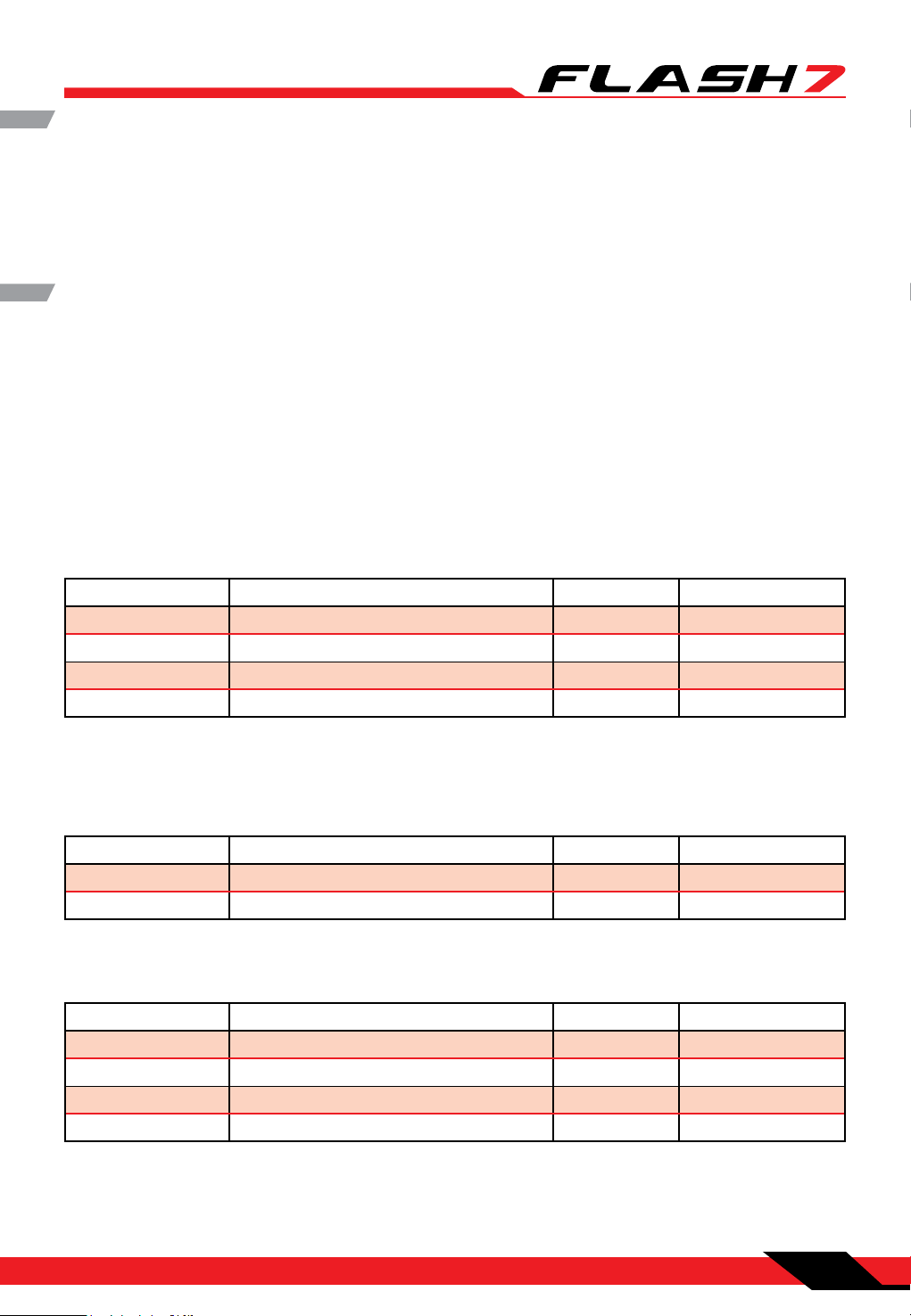
Available Receivers
Optima Series 2.4GHz Receivers
Model Size Weight Stock Number
Optima 6 Lite 1.76 x 1.11 x 0.29in (44.9 x 18.4 x 7.40mm) 0.33oz (9.4g) 29438
Optima 6 1.81 x 0.82 x 0.47in (46.1 x 21.3 x 12.1mm) 0.52oz (15g) 28410
Optima 7 2.20 x 0.79 x 0.43in (56.9 x 20.8 x 11.6mm) 0.60oz (17g) 28414
Optima 9 1.85 x 1.14 x 0.59in (47.7 x 29.1 x 15.5mm) 0.77oz (22g) 28425
Operating Voltage: 3.7~8.4V from a receiver battery or BEC circuit from an Electronic Speed Control
4.8~35v Using SPC Function
Current Drain: 30mA
Maxima Series 2.4GHz Receivers
Model Size Weight Stock Number
Maxima 6 1.29 x 0.81 x 0.42in (33 x 20.8 x 10.7mm) 0.22oz (6.4g) 27524
Maxima 9 1.45 x 0.97 x 0.57in (37 x 24.4 x 14.6mm) 0.28oz (8.1g) 27525
Operating Voltage: 3.7~8.4V from a receiver battery or BEC circuit from an Electronic Speed Control
Current Drain: 30mA
Minima Series 2.4GHz Receivers
Model Size Weight Stock Number
Minima 6 T 1.19 x 0.81 x 0.27in (30.4 x 20.8 x 7.1mm) 0.22oz (6.5g) 26610
Minima 6 E 1.24 x 0.81 x 0.42in (31.7 x 20.8 x 10.9mm) 0.28oz (8.1g) 26612
Minima 6 Lite 1.22 x 0.77 x 0.33in (31.2 x 19.5 x 8.5mm) 0.14oz (4g) 26614
Minima 6S 1.19 x 0.81 x 0.27in (30.4 x 20.8 x 7.1mm) 0.19oz (5.4g) 26615
Operating Voltage: 3.7~8.4V from a receiver battery or BEC circuit from an Electronic Speed Control
Current Drain: 30mA
Section 1: Introduction
9
Page 11

7 Channel 2.4 GHz Aircraft Computer Radio System
7 Channel 2.4 GHz Aircraft Computer Radio System
Terms and Icons
Glossary of Terms
AFHSS 2.4GHz Signal: Hitec’s 2.4GHz R/C signal protocol. Adaptive Frequency Hopping Spread Spectrum.
Telemetry: Data signal from the model, transmitted to the transmitter.
Range Check: A ground check of the signal strength between the transmitter and receiver done before
ying.
Link (ID Setting): Link or “binding” a 2.4GHz receiver to its master transmitter.
HPP-22 PC Interface: PC interface accessory for storing model memories and updating rmware.
Icon Identication
MODEL: The model menu contains the model programming for the active model.
ACRO: Menu for xed wing, glow, gas and some electric models.
GLID: Menu for gliders and some electric models.
HELI: Menu for rotary wing aircraft.
AILE: Aileron for xed wing menus and the “roll” swash input for helis.
ELEV: Elevator for xed wing menus and the “pitch” swash input for helis.
RUDD: Rudder for xed wing menus and the “yaw”, or tail rotor input for helis.
INH: Inhibit is used to “turn o” a function.
ACT: Active, “turns on” a function.
NULL: “No switch” selected, the function or feature will be “on” all the time.
AUX: An “open” channel, without a control assigned to it.
J1: Right gimbal, up and down control.
J2: Right gimbal, side to side control
J3: Left gimbal, up and down control.
J4: Left gimbal side to side control.
T1: J1 control trim.
T2: J2 control trim.
T3: J3 control trim.
T4: J4 control trim.
RS: Right slider control.
LS: Left slider control.
10
Section 1: Introduction
Page 12
7 Channel 2.4 GHz Aircraft Computer Radio System
7 Channel 2.4 GHz Aircraft Computer Radio System
Warning
TipTip
Powering the Flash 7
The Flash 7 includes a 4 x AA battery tray for use with either Alkaline or rechargeable AA size batteries.
The Flash 7 is capable of operating on 4.8 – 8.4 volts DC. This wide range voltage exibility allows you to
use either 4 NiMh cells or a 2 cell LiPo, LiFe or Li-Ion battery pack.
Make sure you use a charger suitable for the battery pack you are using. It is recommended that
you remove the battery from the transmitter when charging it.
Selecting the Battery Type
The Flash 7’s default battery type is Alkaline which has a warning threshold of 4.0 volts. If you choose to
use a dierent type of battery you must select the battery type in the System Management menu.
The preset warning thresholds for each type are
Alkaline 4.0 Volts
NiMh or NiCd 4.3 Volts
LiPo 7.0 Volts
LiFe 6.0 Volts
Power Meter
On the home screen of the Flash 7 you can visually see the voltage reading as well as a bar indicating the
amount of power left in the battery.
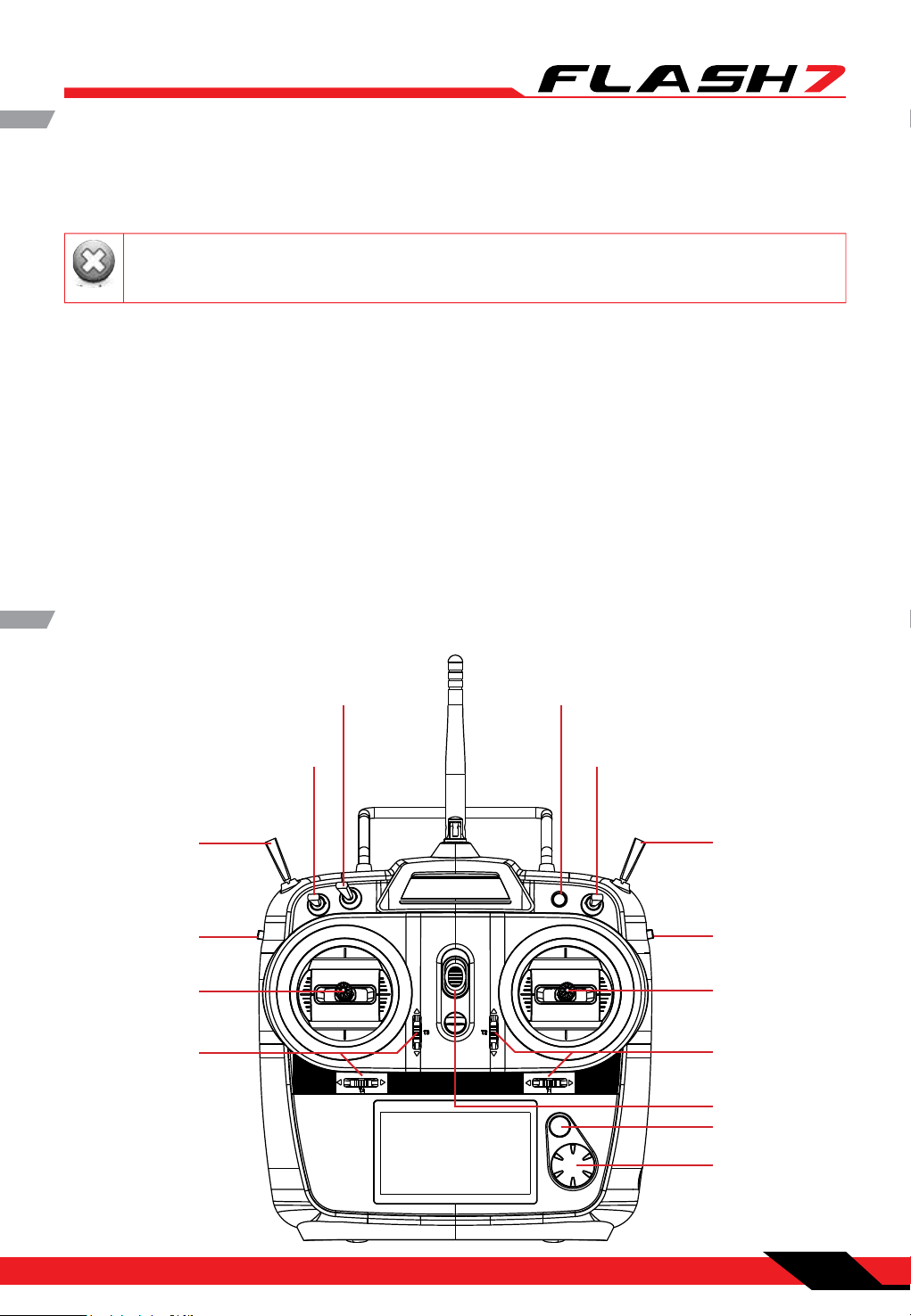
Transmitter Controls
Switch B
2 Position
Switch A
2 Position
Switch E
3 Position
Left Slider Right Slider
Left Gimbal
J3/J4
Left Gimbal Trims Right Gimbal Trims
Button C
Momentary Contact
Switch D
2 Position
Switch F
Momentary Contact
Right Gimbal
J1/J2
On/O Switch
Back Button
Jog Dial
Scroll/Enter
Section 1: Introduction
11
Page 13
7 Channel 2.4 GHz Aircraft Computer Radio System
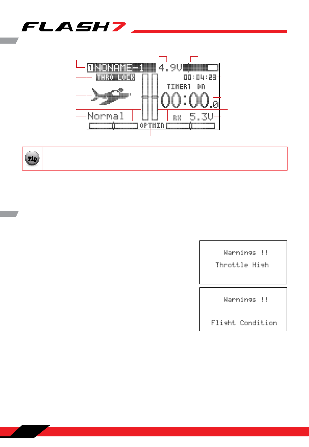
Main Menu
TipTip
7 Channel 2.4 GHz Aircraft Computer Radio System
Model Name Battery Voltage Battery Capacity Remaining
Throttle Lock
Model Type
Left Trim Indicators
Flight Condition
Spectra Reciever Type Setting
From the main menu, you can quickly access certain settings by scrolling to them and pressing
the jog dial.
The following items have the quick access feature:
Model Name to access the Model Select menu.
Spectra Reciever Type to access the Spectra menu.
Time to access the Timers menu.
Transmitter Warnings
The Flash 7 has a few warning alarms that you should be aware of.
Start Up Warnings
High Throttle
If the throttle is positioned above idle during the system “bootup to transmit” process, a warning beep will occur and the
following warning screen will be displayed.
Total in Use Time for
Model Memory Slot
Timer number and Type
Right Trim Indicators
RX Voltage(SPC)
Condition on Warning
If you have ight conditions and other mixing programmed for
the active model and they are switched “on” during the “bootup to transmit” process, a warning sound will occur and the
following warning screen will be displayed.
In Flight Warnings
If the transmitter should start a continuous beeping during ight, land immediately and evaluate the
cause of the warning. There are two warnings that may occur in ight.
Low Transmitter Battery Warning
When the transmitter battery power falls to a critically low level, a warning sound will occur.
Low Aircraft Battery Warning
When using the Optima series of receivers and the on-board battery or the battery connected to the SPC
port is critically low, your transmitter will start beeping warning you that you should land immediately.
This feature does not occur when using single direction receivers such as the Maxima and Minima series
of receivers.
12
Section 1: Introduction
Page 14
7 Channel 2.4 GHz Aircraft Computer Radio System
7 Channel 2.4 GHz Aircraft Computer Radio System
C
H
1
C
H
2
C
H
3
C
H
4
C
H
5
C
H
6
C
H
7
CH8
BAT/9
TX
TX TX
TX
RX
90˚
Recommended installation
method to optimize
receiver performance
CH1
CH2
CH3
CH4
CH5
CH6
CH7
CH8 BAT/9
Note
TipTip
Tip
Caution
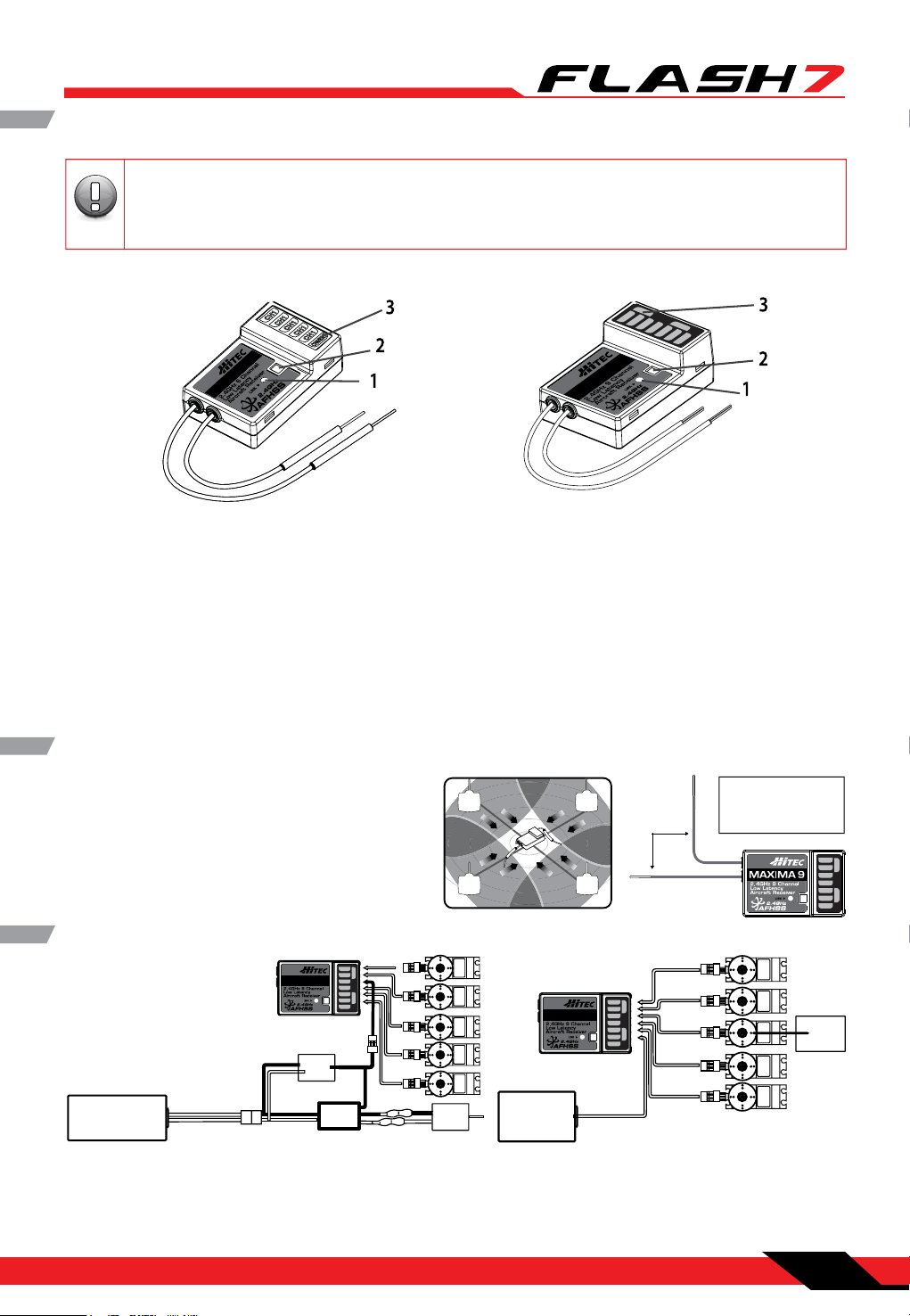
Maxima Series Receivers
The Maxima series is designed for use with G2 AFHSS radios such as the Aurora 9X and Flash
series. USE ONLY Digital SERVOS with the Maxima receivers. Analog servos cannot be used with
the Maxima series receivers.
MAXIMA 6 MAXIMA 9
1. Function Button: Used for binding the receiver to the Flash 7 and entering the FAIL-SAFE or Hold
feature.
2. Dual LED Status Indicator: Indicates the set-up process codes and current status of the receiver.
3. Channel Output and Battery Input Ports: The ports for battery power input and servos, gyros and
other accessories’ output ports are located at the side end of the Maxima receivers.
4. Low Battery Warning: If the receiver’s battery levels fall below 3.6V, the RED LED will ash.
5. FAIL-SAFE/Hold Mode Selectable: Servos and other accessories position can be set with a FAIL-SAFE
point if power to the receiver is lost.
Maxima Series Receiver Antenna Installation
The Maxima receiver series antenna system was
created to provide the optimum signal capture
capability. Our two antennas must be installed
properly. Refer to the illustration below.
Maxima Series Receiver Connection Diagrams
Power Battery
Electric powered aircraft with Electronic Speed Control
Use this method on electric planes using ESCs
providing power to the receiver and servo functions.
CH1
CH2
BAT/9
CH3
CH4
CH5
CH8
CH6
CH7
BEC
ESC
SERVO
CH1
CH2
CH3
CH4
CH5
CH8 BAT/9
CH6
CH7
Engine
SERVOSERVO SERVO SERVO
Motor
SERVO
SERVOS ERVO SERVO
SERVO
Receiver
Battery
Glow, gas or electric powered aircraft using a
separate receiver battery supply.
Follow this connection diagram when using a
regulated Li-Po, or 4.8 to 6V receiver battery.
Section 1: Introduction
13
Page 15
7 Channel 2.4 GHz Aircraft Computer Radio System
7 Channel 2.4 GHz Aircraft Computer Radio System
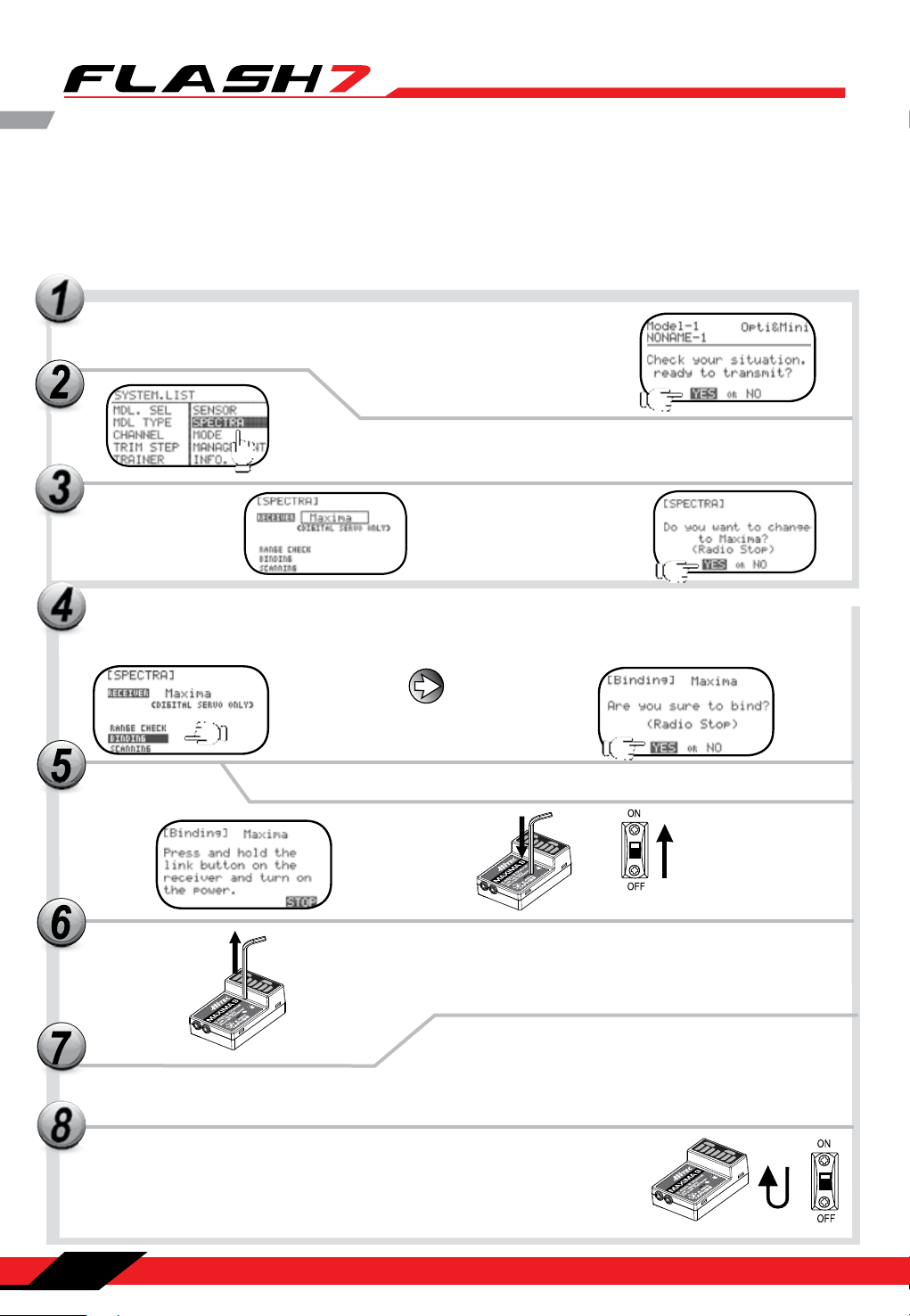
Maxima Series Receiver Connection Diagrams
Your Hitec AFHSS system uses a communication protocol that links and binds the Hitec 2.4GHz receiver
to your transmitter. Once the receiver and transmitter are “bound”, no other transmitter can interfere with
your receiver during its operation. In the case of multiple model memory transmitters, you can bind as
many Hitec 2.4GHz receivers to your transmitter, one per model memory, as necessary. Each transmitter
and receiver set is paired at the factory for your convenience.
Turn on the transmitter and select “yes” to the “Ready to Transmit” prompt by
pressing the jog dial.
Press the jog dial and back button simultaneously to enter the System
Menu list. From here scroll to the SPECTRA function and press the jog
dial to enter the Spectra setup menu.
Press the jog dial to
activate the receiver
selection and scroll
to the “Maxima”
receiver.
Press the jog dial to save your
setting. When prompted to
change the receiver type select
yes and press the jog dial to
conrm your choice.
Now when prompted if you are “Ready to Transmit” select “Yes” and push the jog dial to conrm your response.
Back at the receiver selection screen, scroll to BINDING and
press the jog dial to enter the binding screen.
Select “yes” if you would like to proceed
with the binding process.
Press and hold the link button on the Receiver and turn on the power.
T/9
A
B
CH1
CH2
CH8
CH3
CH4
CH5
CH6
CH7
Release the link button. Both RED and BLUE LEDs will be blinking rapidly to nd
/9
CH1
CH2
CH3
the transmitter’s signal.
AT
B
CH8
CH4
CH5
CH6
CH7
When the LED stops blinking, press the jog dial to get to the next screen. The blue
LED will glow solid.
8
Turn the power to the receiver o, then back on. Check for a solid blue LED light . Once
it’s on, press the jog dial to FINISH the binding process. Make sure all functions are
working properly before ying your model.
14
Section 1: Introduction
BAT/9
CH1
CH2
CH8
CH3
CH4
CH5
CH6
CH7
Page 16
7 Channel 2.4 GHz Aircraft Computer Radio System
7 Channel 2.4 GHz Aircraft Computer Radio System
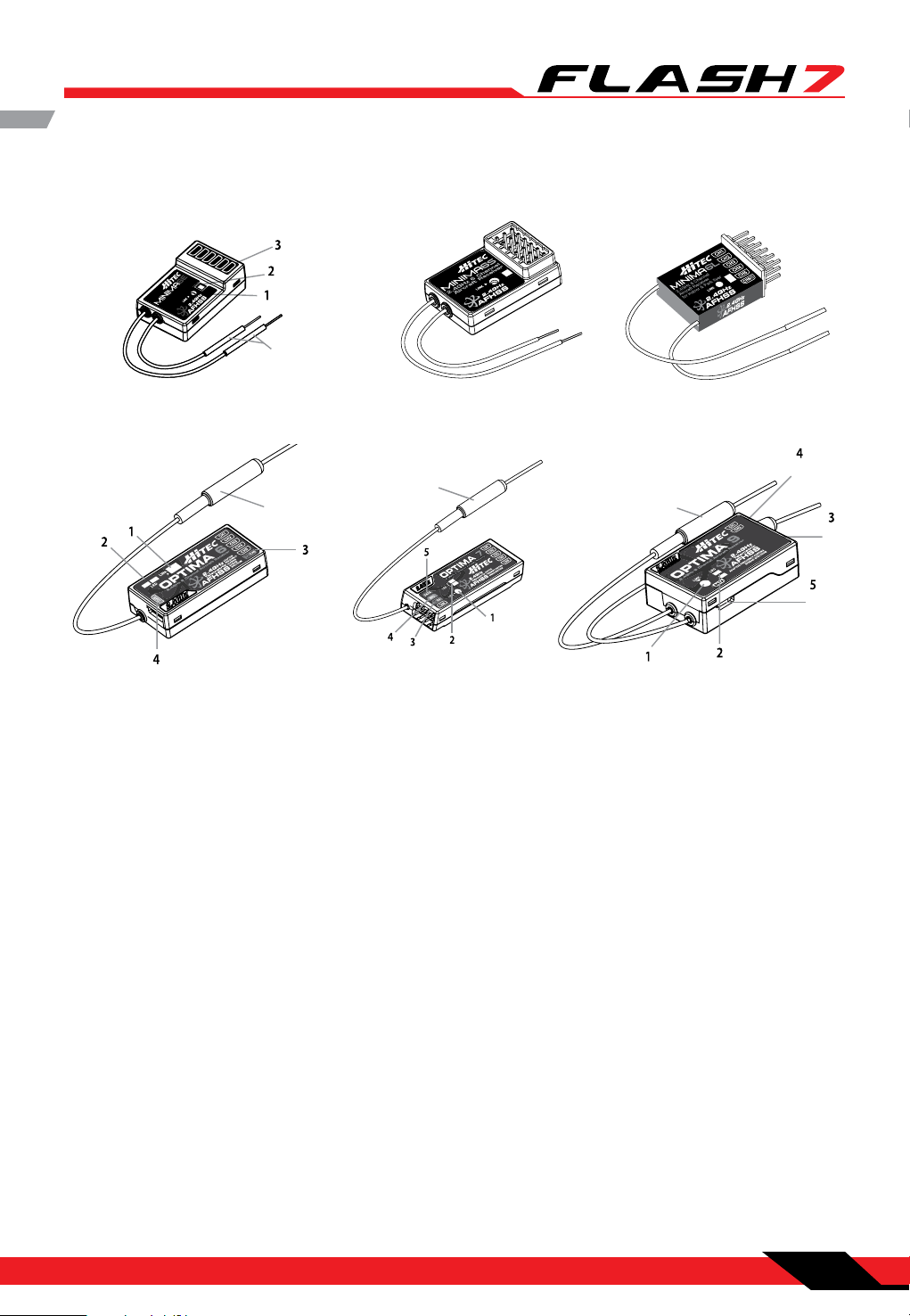
Optima and Minima Series Receivers
The following information contains the complete directions on how to use the Optima and Minima series
receivers (version 3.00(0). We encourage you to review this information before using these products.
CH1
CH1
CH1
CH1
CH1
CH6/BAT
Hz 6 Channel
Aircraft Receiver
2.4G
6
MINIMA 6S MINIMA 6LMINIMA 6S & MINIMA 6T
(6T output block is on top)
6
6
6
OPTIMA 7
(6L utilizes a soft case and exposed output block)
OPTIMA 9OPTIMA 6 & OPTIMA 6 LITE
1. Function Button: Used for binding the receiver to a module or Hitec 2.4 built-in transmitters, entering
the FAIL-SAFE or Hold feature.
2. Dual LED: Status Indicator: Indicates the set-up process codes and current status of the receiver.
3. Channel Output and Battery Input Ports: The ports for battery power input and servos, gyros and
other accessories’ output ports are located at the side.
4. SPC (Supplementary Power Connection)*: Power the Optima and Minima receivers function with up
to a 35V. electric aircraft motor battery.
5. Telemetry Sensor and Data Port*: A three pin servo plug connector port is featured on the Optima 7
and Optima 9 (Optima 6 is not applicable.) Using the HPP-22 PC interface accessory, this port serves to
facilitate upgrading the device’ s software and interfacing the optional onboard sensor station.
6. BODA (Boosted Omni Directional Antenna) System*: Hitec’s exclusive 2.4GHz BODA System will show
you another way of using our 2.4GHz systems. The single Omni-directional antenna booster makes it
much easier to install the 2.4GHz antenna. Intensive tests have proven that the single BODA system
in our 6 & 7 channel systems is better than or equal to our competitor’s dual antenna systems while
our Optima 9 receiver features a dual BODA system to give the added security that larger models need.
Installation is easy and simple, insert the antenna into the supported antenna holder and stick it to the
desired spot you wish to install.
Section 1: Introduction
15
Page 17
7 Channel 2.4 GHz Aircraft Computer Radio System
7 Channel 2.4 GHz Aircraft Computer Radio System
Optima and Minima Series Receivers cont.
Compatibility:
The OPTIMA & MINIMA receivers are compatible with transmitters using the Hitec AFHSS 2.4 GHz system,
such as, Spectra 2.4 module or dedicated built-in module AFHSS 2.4 Hitec transmitters.
FAIL-SAFE/Hold Mode Selectable:
Servos and other accessories can be set with a FAIL-SAFE point if power to the receiver is lost.
Jumper*:
The jumper is installed at the factory and is used when the receiver is powered by an electronic speed
control, a commercially available B.E.C. (battery eliminator circuit), dedicated 4.8 to 6V. NiMH battery pack,
or regulated Li-Po battery. The jumper is removed when the receiver is powered using the SPC feature.
*These functions/ features are only for OPTIMA series receivers.
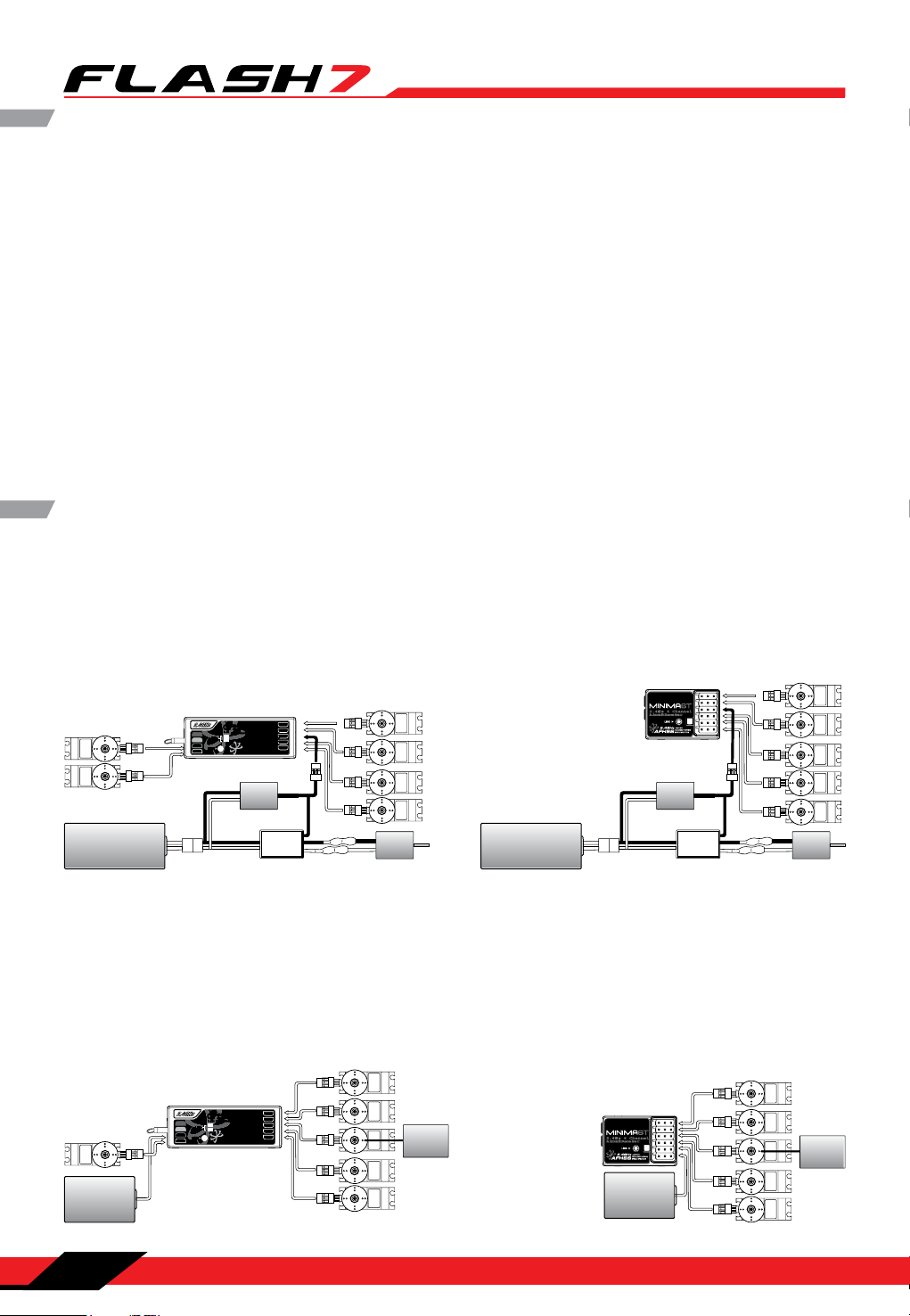
Common Receiver Connection Diagrams
Electric powered aircraft with Electronic Speed Control: This conguration is appropriate for electric
planes using ESCs providing power to the receiver and servo functions.
2.4GHz 6 Channel
Aircraft Receiver
BEC
ESC
SERVO
SERVO
Power Battery
z 7 Channel Aircraft Receiver2.4GHz 7 Channel Aircraft Receiver
2.4GHz
Telemetric
AFHSS
BEC
ADAPTIVE
FREQUENCY HOPPING
SPREAD SPECTRUM
CH1
CH2
CH3
CH4
CH5
ESC
Motor
SERVOS ERVO
SERVO
SERVO
Power Battery
OPTIM A 7OPTIMA 7
2.4GH
DATA
LED
LED
SPC
BAT/CH7
LINK
LINK
CH6
Glow, gas or electric powered aircraft using a separate receiver battery supply: Follow this connection
diagram when using a regulated Li-Po, or 4.8 to 6V receiver battery.
SERVO
AFHSS
CH1
CH2
CH3
CH4
2.4GHz
ADAPTIVE
Telemetric
FREQUENCY HOPPING
SPREAD SPECTRUM
CH5
Engine
SERVOS ERVO
SERVOSERVO
2.4GHz 6 Channel
Aircraft Receiver
Receiver
Battery
OPTIM A 7OPTIMA 7
2.4GHz 7 Channel Aircraft Receiver2.4GHz 7 Channel Aircraft Receiver
DATA
LED
LED
SPC
BAT/CH7
LINK
LINK
CH6
SERVO
Receiver
Battery
SERVO
SERVOS ERVO SERVO
SERVO
Motor
SERVO
Engine
SERVOSERVOS ERVO SERVO
16
Section 1: Introduction
Page 18
7 Channel 2.4 GHz Aircraft Computer Radio System
7 Channel 2.4 GHz Aircraft Computer Radio System
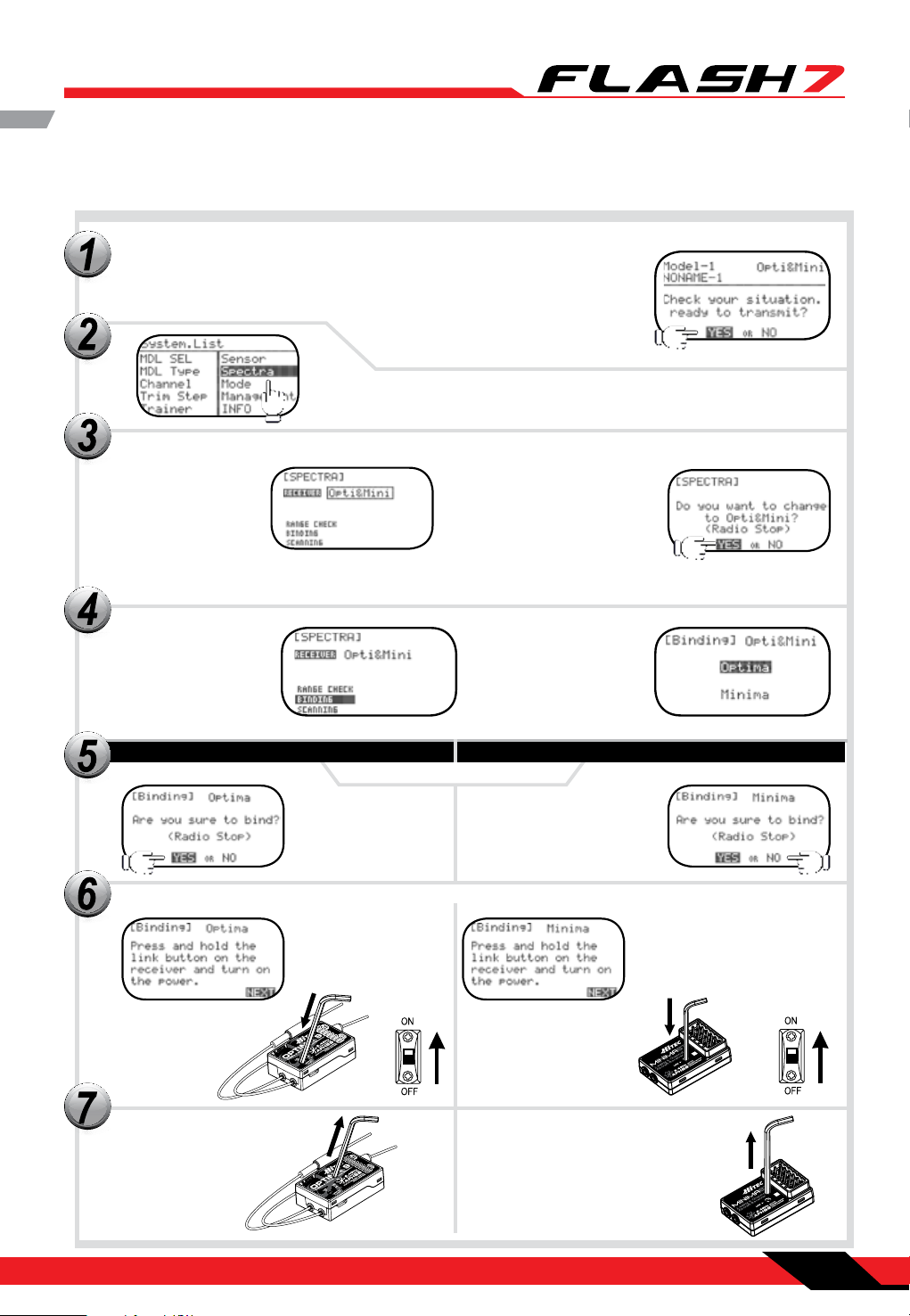
Optima and Minima Series Receiver Link (ID-Setting or Bind)
Your Hitec AFHSS system uses a communication protocol that links and binds the Hitec 2.4GHz receiver to
your transmitter. Once the receiver and transmitter are “bound”, no other transmitter can interfere.
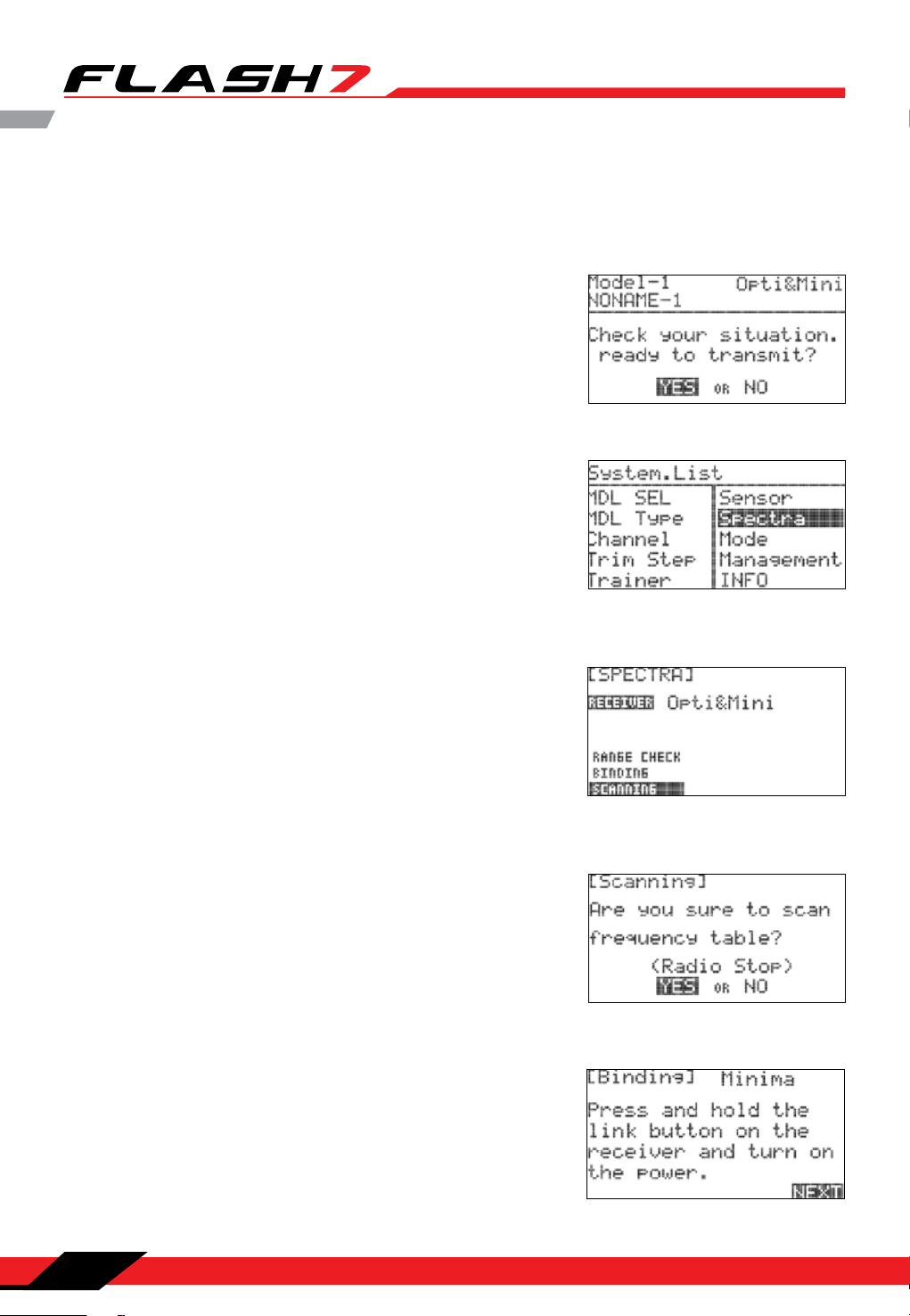
Turn on the transmitter and select “Yes” to the “Ready to Transmit” prompt by
pressing the jog dial.
Press the jog dial and back button simultaneously to enter the System
Menu list. From here scroll to the SPECTRA function and press the jog
dial to enter the Spectra setup menu.
Press the jog dial to
activate the receiver
selection and scroll
to the “Opti&Mini”
receiver.
Back at the receiver
selection screen, scroll
to BINDING and press
the jog dial to enter
the binding screen.
OPTIMA
Press and hold the link button on the Receiver and turn on the power.
Press the jog dial to save your
setting. When prompted to
change the receiver type select
“Yes” and press the jog dial to
conrm your choice.
Select the type of receiver
you are using, either
Optima or Minima, and
push the jog dial to
conrm your selection.
MINIMA (MAXIMA)
Select “Yes” for binding.
Release the link button. Release the Link button, both RED and
2.4GHz 6 Channel
Aircraft Receiver
BLUE LEDs will be blinking rapidly to
nd the transmitter’s signal.
Section 1: Introduction
2.4GHz 6 Channel
Aircraft Receiver
17
Page 19
7 Channel 2.4 GHz Aircraft Computer Radio System
7 Channel 2.4 GHz Aircraft Computer Radio System
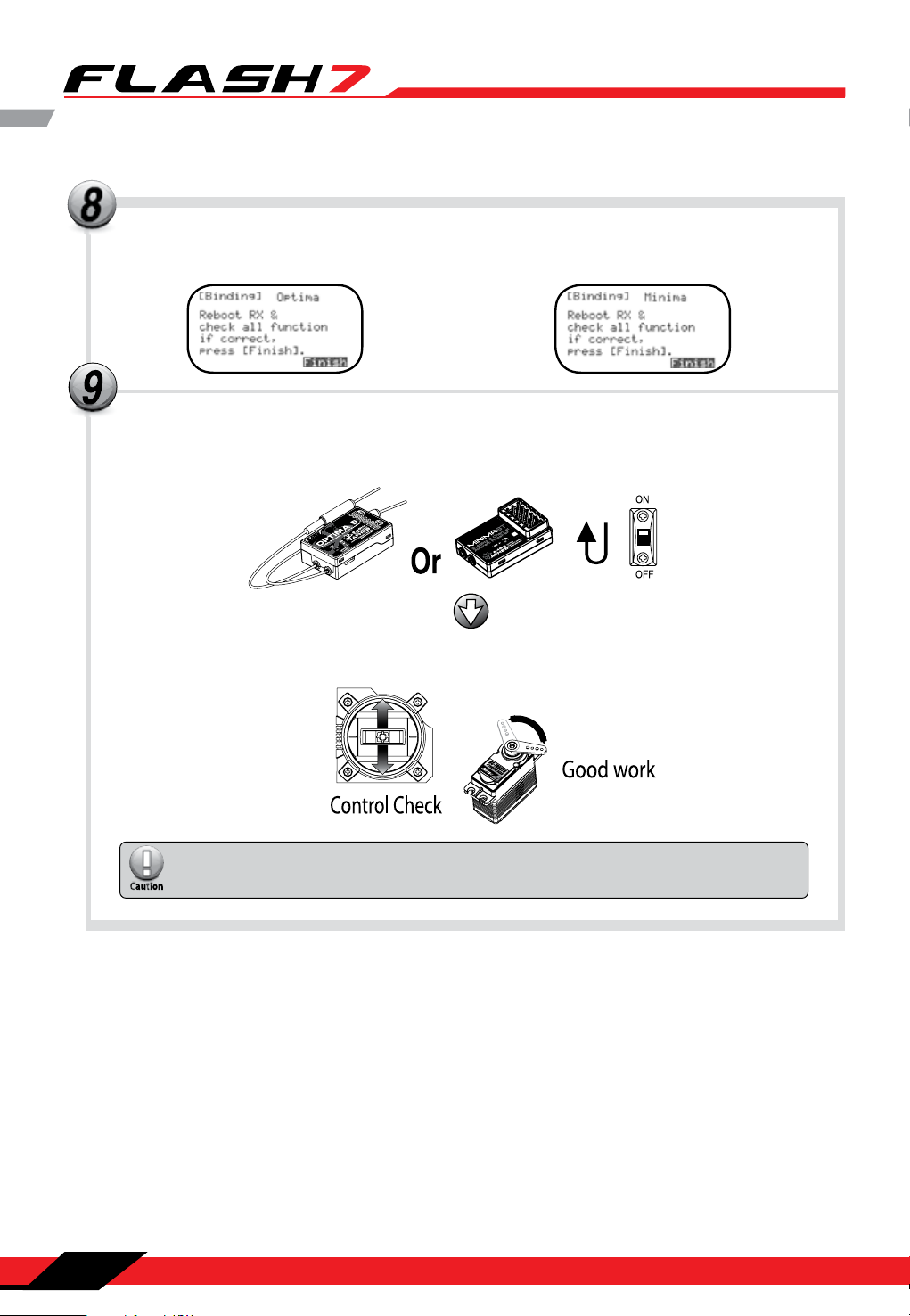
Optima and Minima Series Receiver Link (ID-Setting or Bind) cont.
When the binding process is completed, it
automatically goes to the nish screen. (The
BLUE and RED LEDs will be solidly on)
Turn the power to the receiver o, then back on. Check for a solid blue LED light. Once on, press the jog dial
to FINISH the binding process. Make sure all functions are working properly before ying your model.
When the LED stops blinking, press the jog
dial to get to the next screen. The blue LED
will glow solid.
If all functions work well, press the Finish icon on the screen to nish binding.
If any function is not working as described, please go back to step 6 and repeat the
binding again.
18
Section 1: Introduction
Page 20
7 Channel 2.4 GHz Aircraft Computer Radio System
7 Channel 2.4 GHz Aircraft Computer Radio System
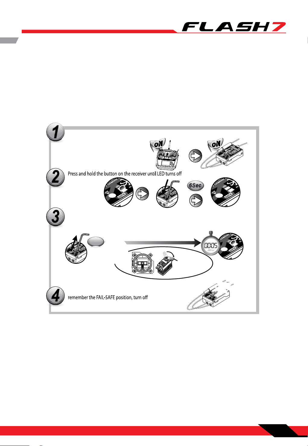
FAIL-SAFE and Hold Mode Setup
If the FAIL-SAFE function is set up and used properly but the receiver signal is somehow interrupted,
the servos will move to your previously stored FAIL-SAFE setup. If you do not activate the FAIL-SAFE
function, the signal is switched o after the HOLD period of 1 sec. This means that the servos become
“soft” and remain in their last commanded position under no load (this may equate to full-throttle!) until
a valid signal is picked up again. In the interest of safety, we recommend that FAIL-SAFE should always
be activated, and the FAIL-SAFE settings should be selected so as to bring the model to a non-critical
situation (e.g. motor idle / electric motor OFF, control surfaces neutral, airbrakes extended, aero-tow
release open, etc.).
Switch on both.
Wait for the system to boot and you have
control over the model.
(approx. 6 second)
Release the button. After 2 seconds both red and blue LEDs blink alternately.
The receiver will count 5 seconds. During that time, move all the transmitter
sticks and other controls to the desired FAIL-SAFE positions (e.g. motor idle,
control surfaces neutral), and hold until the blinking stops.
2Sec.
When the blinking stops, the system will temporarily
the system to save and exit.
6Sec.
www.hitecrcd.com
Fail-Safe position
Testing the FAIL-SAFE Setting
Move the sticks to positions other than the FAIL-SAFE settings, and then switch o the transmitter. The
servos should now move to the FAIL-SAFE positions previously stored after the one second HOLD period.
How to turn FAIL-SAFE O and reactivate the Hold Mode
a. Switch on the transmitter, then the receiver. Wait for the system to boot and you have control over the
model.
b. Press and hold the receiver function button for 6 seconds and release it. After 2 seconds, the red and
blue LEDs will blink rapidly.
c. Immediately press the receiver function button once.
d. FAIL-SAFE Mode is now deactivated and HOLD mode is activated.
e. Turn the transmitter o, then the receiver o.
f. Turn the system back on to use it.
Section 1: Introduction
19
Page 21

7 Channel 2.4 GHz Aircraft Computer Radio System
7 Channel 2.4 GHz Aircraft Computer Radio System
Telemetry System
The Hitec Spectra 2.4 System and Optima Series receivers feature full telemetry capabilities (except
Optima 6) and include a Low Receiver Battery Warning as a basic function.
Functions (Available with Optima 7 and 9):
Hitec oers a wide variety of telemetry sensors designed to work with both fuel and electric powered
aircraft. Check our website at www.hitecrcd.com for the latest available telemetry accessories.
- The telemetry function is applicable for OPTIMA series receivers only.
Note
Warning
- The actual battery voltage level could be dierent.
- When the 2.4GHz system and High Voltage servos are used together, we strongly
recommend using fully charged large capacity battery packs.
20
Section 1: Introduction
Page 22
7 Channel 2.4 GHz Aircraft Computer Radio System
7 Channel 2.4 GHz Aircraft Computer Radio System
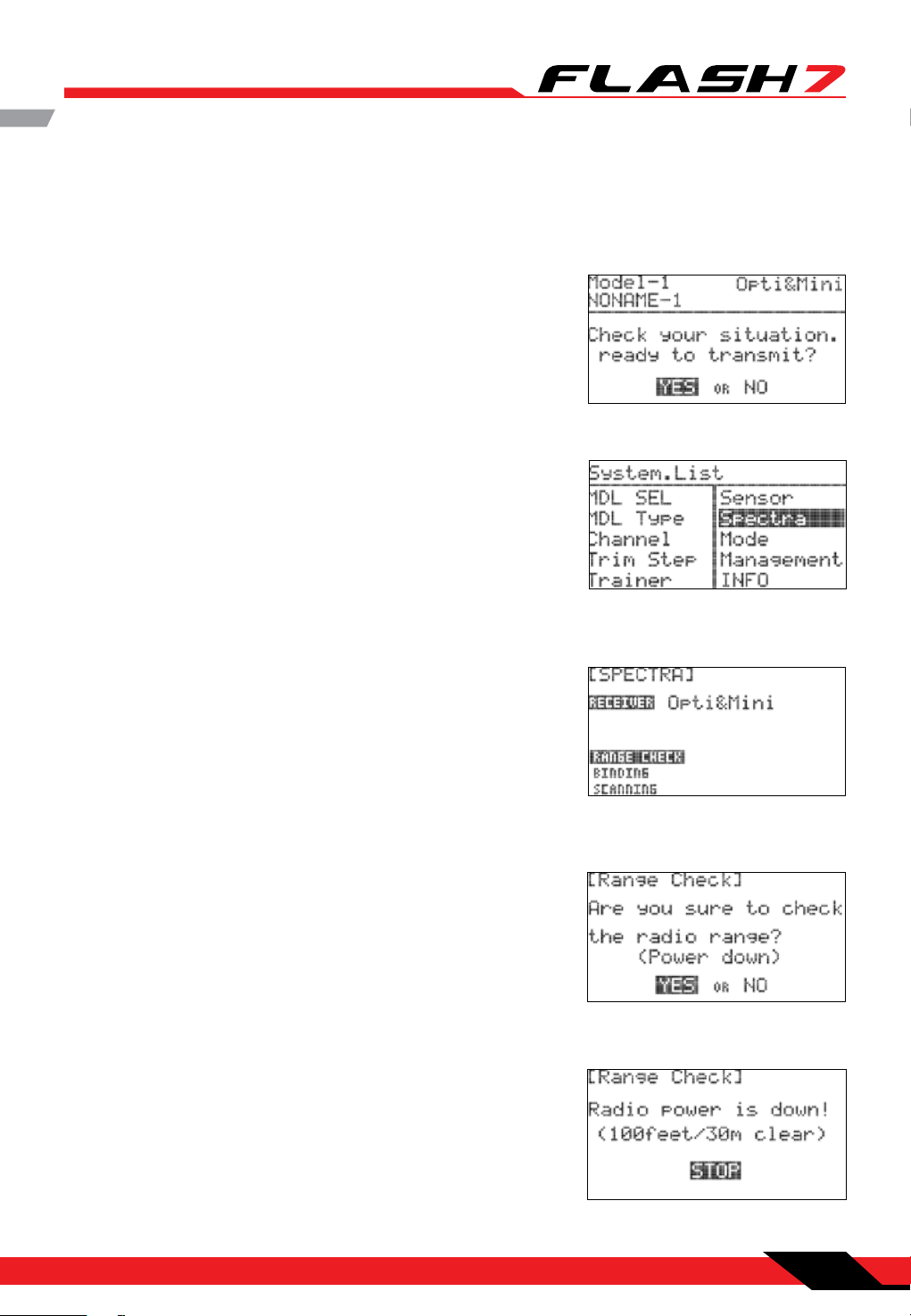
Range Check Function
It is critical that before each ight session you perform a range check that conrms the signal between
the receiver and transmitter is appropriate. To do a range check, use a power-down mode to reduce the
transmitter signal strength. During this power-down mode, you should walk away from the secured
aircraft carrying the transmitter to a distance of approx. 30 meters, to test the eective range.
1. Turn on the transmitter and select “Yes” from the “Ready to
Transmit” prompt by pressing the jog dial.
2. Press the jog dial and back button simultaneously to enter the
System Menu list. From here, scroll to the SPECTRA function
and press the jog dial to enter the Spectra setup menu.
3. Scroll to the RANGE CHECK and push the jog dial to enter the
range check function.
4. If you are sure you want to proceed with the range check,
select “Yes” and press the jog dial to continue.
5. Walk away from the secured aircraft carrying the transmitter
to a distance of approx. 30 meters, to test the eective range.
Once you have completed the range check, push the jog dial
to end the range check.
Section 1: Introduction
21
Page 23
7 Channel 2.4 GHz Aircraft Computer Radio System
7 Channel 2.4 GHz Aircraft Computer Radio System
Scan Mode
In Scan Mode the transmitter and receiver will scan all available channels every time you turn it on.
It will then choose the cleanest frequencies to use. Scan Mode is preferable to use when ying in a
crowded 2.4GHz environment.
1. Turn on the transmitter and select “Yes” to the “Ready to
Transmit” prompt by pressing the jog dial.
2. Press the jog dial and back button simultaneously to enter the
System Menu list. From here scroll to the SPECTRA function
and press the jog dial to enter the Spectra setup menu.
3. Scroll to the Scanning selection and push the jog dial to enter
the Scanning function.
4. If you are sure you want to proceed with the Scanning, select
“Yes” and press the jog dial to continue.
5. If Scan Mode link is successful, you will be prompted to reboot
the receiver.
22
Section 1: Introduction
Page 24
7 Channel 2.4 GHz Aircraft Computer Radio System
7 Channel 2.4 GHz Aircraft Computer Radio System
Scan Mode cont.
6. Check to see that all functions are operating correctly. If they
do, press Finish. You now have successfully bound your
receiver in scan mode.
SLT Technology
In addition to our proprietary AFHSS technology the Flash 7 has the ability to transmit using Secure Link
Technology (SLT). This allows you to y the numerous Tx-Ready models available on the market. For more
information visit Tx-Ready.com for models utilizing this technology. Follow these instructions to utilize
SLT with your Flash 7.
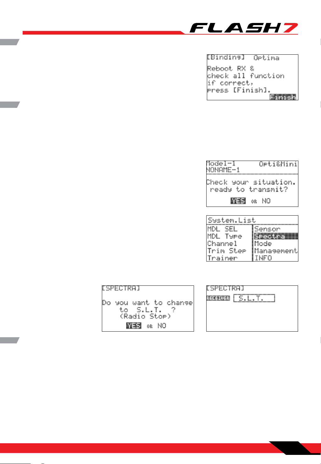
1. Turn on the transmitter and select “Yes” to the “Ready to
Transmit” prompt by pressing the jog dial.
2. Press the jog dial and back button simultaneously to enter the
System Menu list. From here scroll to the SPECTRA function
and press the jog dial to enter the Spectra setup menu.
3. Press the jog dial to activate the receiver selection and scroll
to the “SLT” receiver.
SLT Binding
The following procedure is for binding typical SLT receivers to the Aurora 9X. These methods may vary
from manufacturer to manufacturer. Check your receiver manual for any variances to these instructions.
1. Turn on the Flash transmitter and when prompted to transmit choose “YES.”
2. Apply power to the Receiver.
3. If the receiver LED ashes once and then stays on, the receiver is already linked to the transmitter and
you can skip to the next section. Otherwise, insert a small diameter screwdriver into the hole marked
“LINK” or “BIND” on the receiver and press the button until the LED on the receiver glows red and then
turns o after about one second.
4. Release the “LINK” or “BIND” button.
Section 1: Introduction
23
Page 25
7 Channel 2.4 GHz Aircraft Computer Radio System
7 Channel 2.4 GHz Aircraft Computer Radio System
Warning
Note
TipTip
Tip
Caution
Note
Airplane Quick Start Guide
The following information is designed to guide you through a simple setup of a standard sport plane or
unpowered glider. The operations shown during this exercise will help you understand many of the basic
programming steps used by the Flash 7.
If you are setting up a powered or un-powered glider, we will be programming your plane into
the ACRO menu for this exercise. Later you can explore the functions found in the GLID menus.
Channel Assignments for a Simple Powered Plane with One or Two Aileron Servos:
Channel 1 - Aileron
Channel 2 - Elevator
Channel 3 - Throttle
Channel 4 - Rudder
Channel 5 - Aileron #2 (if used)
Channel Assignments for a Simple Un-Powered Glider:
Channel 1 - Aileron (plug rudder or aileron servo in Ch. #1)
Channel 2 – Elevator
This exercise assumes two things:
1. That you have already installed the servos in your aircraft.
2. That you bound (linked) the receiver to your transmitter.
For safety reasons during this set-up exercise on an electric powered plane, remove the
propeller.
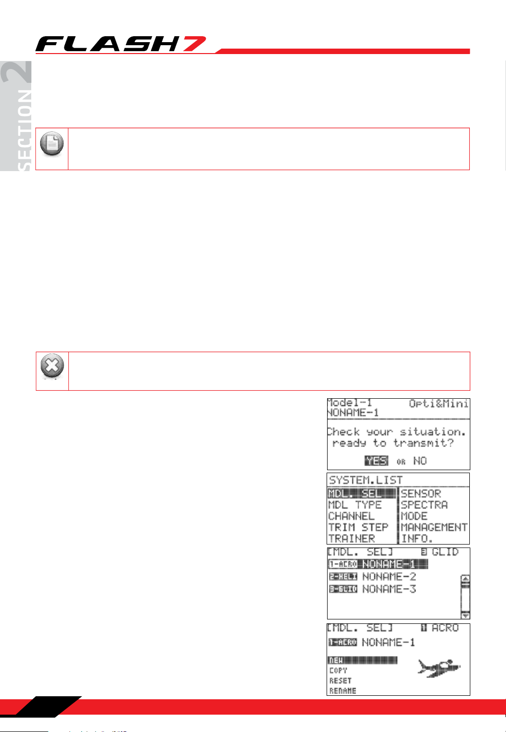
1. Turn on the transmitter. Do not turn on the airplane.
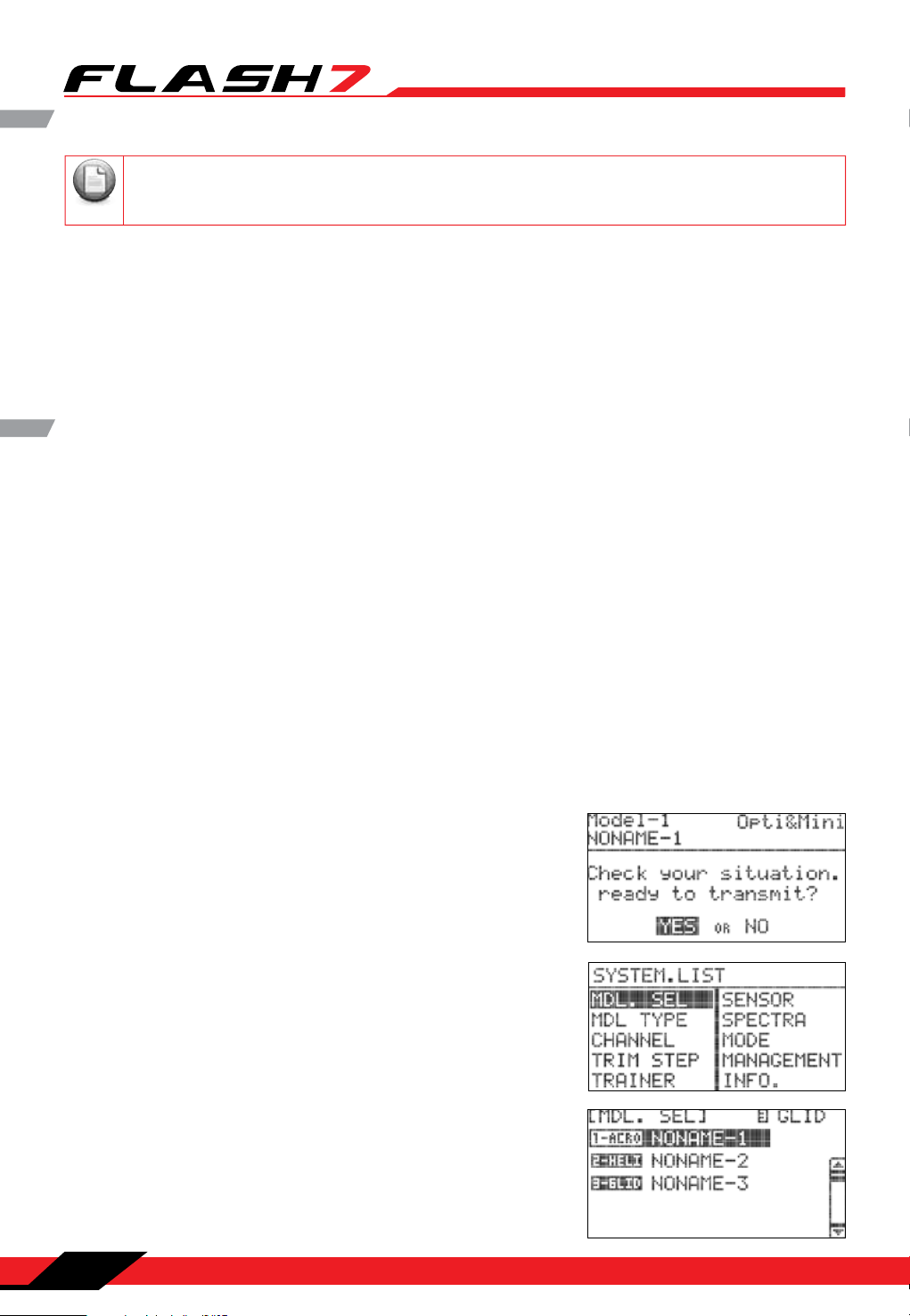
2. When prompted if you are “Ready to Transmit” select “No”.
3. Press the jog dial and back button simultaneously to enter the
System Menu list.
4. From the System Menu list choose MDL.SEL to enter the
model setup.
5. Select the rst default model (NONAME-1) and press the jog
dial to bring up the model maintenance prompts. Select
“NEW” to create a new model.
24
Section 2: Quick Start Guides
Page 26
7 Channel 2.4 GHz Aircraft Computer Radio System
7 Channel 2.4 GHz Aircraft Computer Radio System
Note
Note
Airplane Quick Start Guide cont.
We are programming a new model into the model memory slot number two, not the model
memory slot one. For the purpose of this exercise it will ensure a fresh model memory with no
existing programming.
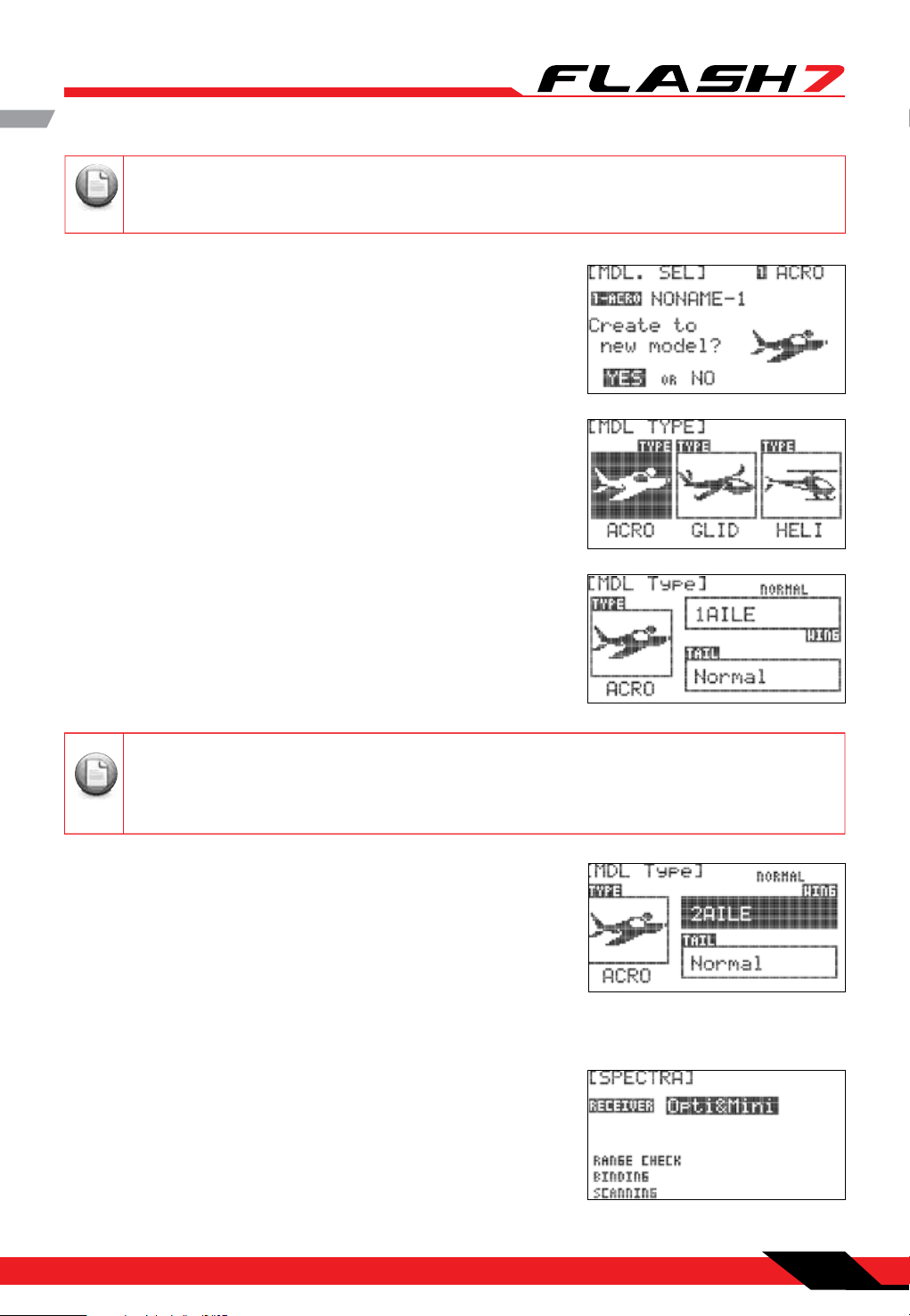
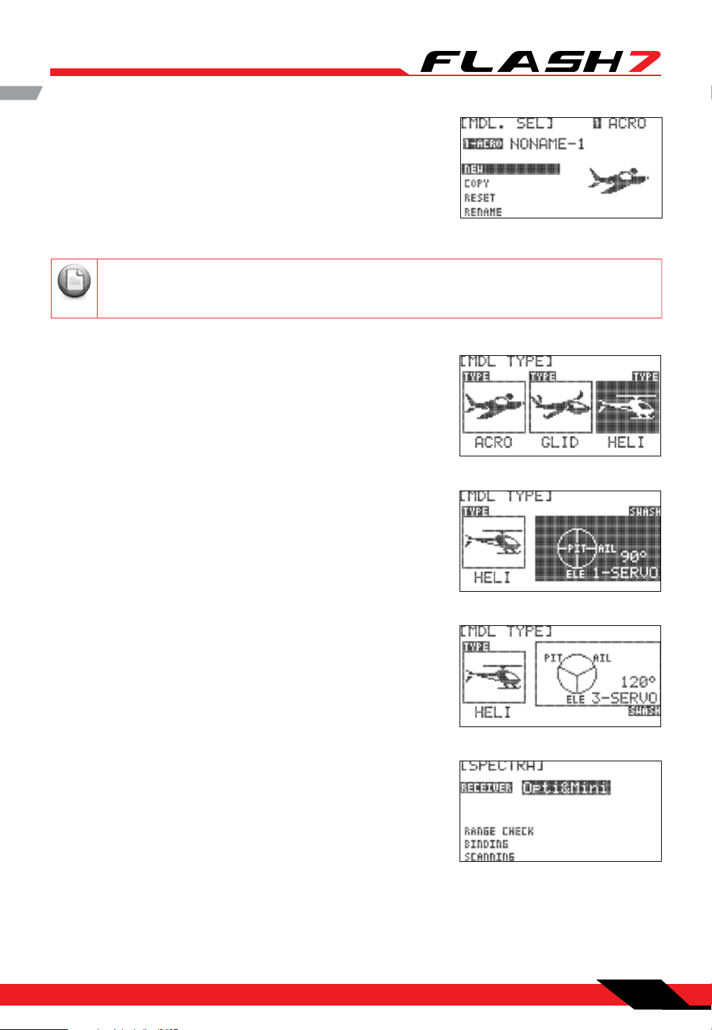
6. When asked to create a new model select “Yes.” This will bring
up the Model Type screen.
Scroll to “Acro/Glid” or “Select Acro/Glid.”
Now scroll to “wing” and press the jog dial to activate the
choices. If you have 1 aileron servo, select 1AILE. If your plane
has two aileron servos, select 2AILE. Press the jog dial once to
conrm your selection.
Depending on what you select here, and for the following menu choices, the radio will
automatically optimize the functions for your choices. In other words, if you select a wing type
without aps, there will be no ap function control in that model memory’s programming
selection.
7. Next, select your plane’s tail type. Select “Normal” and press
the jog dial once to conrm your entry .
8. Now press the back button once. You will be prompted to
choose the receiver type. Press the jog dial once to activate
the receiver selections and scroll to the receiver you have in
your aircraft. Press the jog dial once to conrm your receiver
selection.
Section 2: Quick Start Guides
25
Page 27
7 Channel 2.4 GHz Aircraft Computer Radio System
7 Channel 2.4 GHz Aircraft Computer Radio System
Note
Airplane Quick Start Guide cont.
If your receiver is not bound/linked to your transmitter you will need to follow the procedures
on pages 18-19 to do so.
9. Turn your transmitter o and then back on. When prompted to transmit, this time select “Yes.” You are
now ready to y a simple model with basic settings. If a more complex setup is needed, refer to sections
4 and 5 for more detailed programming instructions.
Helicopter Quick Start Guide
The following information is designed to guide you through a simple setup of a basic 120 cyclic collective
pitch mixing (CCPM) helicopter with a y bar. The operations shown during this exercise will help you
understand many of the basic programming steps used by the Flash 7 when programming a basic
helicopter setup.
Channel Assignments
Channel 1 – Roll Cyclic / Aileron
Channel 2 – Pitch Cyclic / Elevator
Channel 3 – Throttle
Channel 4 – Tail Rotor Pitch / Rudder
Channel 5 – Gyro Function
Channel 6 – Collective Pitch
1. Turn on the transmitter. Do not turn on the helicopter.
2. When prompted if you are “Ready to Transmit” select “No.”
3. Press the jog dial and back button simultaneously to enter the
System Menu list.
4. From the System Menu list choose MDL.SEL to enter the
model setup.
26
Section 2: Quick Start Guides
Page 28
7 Channel 2.4 GHz Aircraft Computer Radio System
7 Channel 2.4 GHz Aircraft Computer Radio System
Note
Helicopter Quick Start Guide cont.
5. Select the rst default model (NONAME-1) and press the jog
dial to bring up the model maintenance prompts. Select
“NEW” to create a new model.
We are programming a new model into the model memory slot number two, not the model
memory slot one. For the purpose of this exercise it will ensure a fresh model memory with no
existing programming.
6. When asked to create a new model select “Yes.” This will bring
up the Model Type screen.
Select HELI to advance to Swash Type. Scroll to Swash Type and
press the jog dial to activate the choices.
7. Scroll through the Swash Type entries until you see 120°
3-SERVO. Press the jog dial to conrm your entry.
8. Now press the back button once. You will be prompted to
choose the receiver type. Press the jog dial once to activate
the receiver selections and scroll to the receiver you have in
your aircraft. Press the jog dial once to conrm your receiver
selection.
9. Turn your transmitter o and then back on. When prompted to transmit, this time select “Yes.” You
are now ready to y a simple helicopter with basic settings. If a more complex setup is needed, refer to
sections 4 and 5 for more detailed programming instructions.
Section 2: Quick Start Guides
27
Page 29

7 Channel 2.4 GHz Aircraft Computer Radio System
7 Channel 2.4 GHz Aircraft Computer Radio System
Note
System Menu
There are two primary menus in the Flash 7 programming structure. The System function Menu and the
Model function Menu. The rst menu we will explore is the System Menu. This menu has all the common
programming function that are available for ACRO, GLID and HELI models. There are also numerous
options for customizing the operating characteristics of the Flash 7 transmitter.
If you have not already programmed a model with the preceding quick start guide, we
encourage you to do so before tackling the System and Model programming sections of the manual.
From the System Menu you can do the following:
MDL.SEL: Model Select Menu.
SELECT: Select an existing model.
NEW: Create a new model.
COPY: Copy one model’s data into a new model memory slot.
RESET: Reset the model memory to the factory defaults.
DELETE: Delete a model memory.
RENAME: Rename the model to a name of your choice.
MDL TYPE: Model Type Menu.
ACRO: Provides programming for most powered xed wing aircraft.
GLID: Provides programming for Gliders both powered and unpowered.
HELI: Provides Helicopter programming functions.
CHANNEL: Model channel assignment Menu. Allows control of any channel to be assigned to a switch or
joystick axis.
TRIM STEP: Trim step size adjustment menu (1-200). Default is 12.
TRAINER: Trainer options menu.
SENSOR: Telemetry sensor setup menu.
SPECTRA: Receiver set-up.
Range Check Mode: Power down mode for performing preight range check.
Binding: Use to bind a new receiver to your Flash 7.
Scanning: Scan the frequency table for the clearest channels.
MODE: Stick mode change Mode 1-4.
MANAGEMENT: System Management Menu.
BACKLIGHT: Adjusts how long the backlight stays on.
CONTRAST: Adjusts the screen contrast.
BATTERY: Used to specify the battery type used in the transmitter: Alkaline, NiMh/NiCD, LiPo or
LiFe.
28
Section 3: System Menu Programming
Page 30

7 Channel 2.4 GHz Aircraft Computer Radio System
7 Channel 2.4 GHz Aircraft Computer Radio System
System Menu cont.
UI FEEDBACK: Turns the user interface sound feedback on or o.
WARNING SETUP: Controls the various transmitter warnings
RF CHECK: Prompts if you are “Ready to Transmit”
HIGH THROTTLE: Warns if the throttle is not in “idle” position
FLIGHT CONDITION: Warns if a ight condition switch is on
INFO: Displays transmitter information such as software version.
Working with the System Menu
1. Turn on the transmitter. When prompted with the “Ready to
Transmit?” message, highlight “NO” and press the jog dial.
2. To access the system menu simultaneously press the back
button and jog dial.
3. The resulting list displays all the features of the system menu
associated with the active model. Full explanations of their
function can be found in the following text.
Model Select Menu
The Model Select menu can be accessed two dierent ways. One method is to highlight the model name
in the main screen and press the jog dial button. The other method is to select “MDL. SEL” from the system
menu.
From the model select menu you can:
Create a new model
Select an existing model to use
Copy one model’s data into a fresh model memory slot
Reset the model memory to factory default settings
Delete a model
Rename a model
Section 3: System Menu Programming
29
Page 31

7 Channel 2.4 GHz Aircraft Computer Radio System
7 Channel 2.4 GHz Aircraft Computer Radio System
Model Select Menu cont.
1. Create a new model: When you create a new model, you
are also prompted to do other setup items. To avoid repetitive
information it is recommended that you read the quick start
guides in order to understand what other steps are required
when creating a new model. The “New” option is only available
if the last model in the list is selected.
2. Select an existing model:
a. Use the jog dial to scroll
through the list of models.
When you have highlighted
the model you want to
work with, press the jog dial
to conrm your selection.
3. Copy one model’s data into another memory slot:
a. If you haven’t already done so, create a new model by following the ACRO or HELI Quick Start
instructions.
b. In the model select menu,
highlight the model you wish
to copy and press the jog dial.
b. Highlight “SELECT” and press
the jog dial.
c. Scroll to “COPY” and press
the jog dial to activate the
destination menu.
c. When asked if you would like to
change the model, highlight
“YES” and press the jog dial.
d. Scroll to select the model
memory slot where you would
like to place the data. Press the
jog dial to conrm your
selection.
e. When prompted to conrm that you want to copy, select “YES”
and press the jog dial to conrm your selection.
30
Section 3: System Menu Programming
Page 32

7 Channel 2.4 GHz Aircraft Computer Radio System
7 Channel 2.4 GHz Aircraft Computer Radio System
Note
Note
Model Select Menu cont.
4. Reset the active model memory slot to factory default settings:
a. Select the model you wish
to reset.
b. Scroll to “RESET” and press
the jog dial.
c. When prompted that you want to reset the model, select yes and
press the jog dial to conrm your entry. You have now cleared all
of the programming for the model. The only settings that will
remain are the model name, receiver type and wing and tail types.
You can only reset the active model.
5. Delete a model memory:
a. In the model select menu, highlight the
model you wish to delete and press the jog dial.
b. Scroll to
“DELETE”
and press
the jog dial.
c. When prompted
that you want to
delete the model,
select yes and
press the jog
dial to conrm
your entry.
6. Rename a model:
a. In the model select menu, highlight the model you wish to rename. Press the jog dial to conrm your
selection.
You cannot delete the active model.
b. Scroll to RENAME and press
the jog dial to enter the
naming screen.
c. In the eld displaying the
current model name, scroll to
the character you want to
change and press the jog dial
to activate it. The cursor will
blink under the active character.
e. Repeat steps c and d until you have renamed the model.
f. Press the back button to return to the model select menu.
d. Use the jog dial to scroll
through the characters and
press it once to select the
character.
Section 3: System Menu Programming
31
Page 33

7 Channel 2.4 GHz Aircraft Computer Radio System
7 Channel 2.4 GHz Aircraft Computer Radio System
Model Type Menu
The model type screen denes the features of the active model. These are the features we told the radio
our model had during the “create a new model” process plus all the default features. Here we can dene
all the choices you have while setting up your aircraft in the Flash 7.
There are three types of aircraft “Model Type” menus:
ACRO: For all xed wing, glow, gas and some electric powered models.
GLID: For all gliders and some electric powered models.
HELI: All Helicopters will use the HELI menu.
Model Type ACRO Menu Programming
1. From the System Menu select MDL TYPE.
2. Press the jog dial once to enter the Model Type Selection
Menu. ACRO is the rst and default selection.
3. Press the jog dial again to enter the ACRO setup menu.
4. Once in the ACRO setup menu you will set your wing and tail
choices. Scroll to the wing selection and press the jog dial to
activate the selections and scroll through the choices.
The choices for Normal ACRO wing type are:
1AILE – Single aileron servo
1AILE+1FLAP – Single aileron servo and single ap
servo
1AILE+2FLAP - Single aileron servo channel and two
ap servos
2AILE – Two aileron servos
2AILE+1FLAP - Two aileron servos and one ap servo
2AIL+2FLAP - Two aileron servos and two ap servos
32
Section 3: System Menu Programming
Page 34

7 Channel 2.4 GHz Aircraft Computer Radio System
7 Channel 2.4 GHz Aircraft Computer Radio System
Model Type ACRO Menu Programming cont.
Additionally there are setups for delta wing type models (Elevon):
2AILE
2AILE+1FLAP
2AILE+2FLAP
5. Once you have selected your wing types, press the jog dial to conrm your selection.
6. Scroll to “TAIL” and press the jog dial to activate the menu. The
choices for tail type are dependent on the type of wing you
selected.
The tail types you may choose with the basic ACRO wing types are:
NORMAL:
Rudder is located on a vertical stabilizer and elevator is on a horizontal stabilizer.
V-TAIL:
Two control surfaces in a V-conguration operate together providing both yaw (rudder) and pitch
(elevator) control.
Ailevator:
Each half of the elevator is controlled by a dedicated servo to provide pitch (elevator), and roll (aileron) control.
The tail choices if you chose one of the Delta Wing types are:
None: For Delta Wing Models without a rudder.
1Servo: For Delta Wing Models with a single rudder servo.
2Servo: For Delta Wing Models with dual rudder servos.
7. Select the tail type that your model has and press the jog dial to conrm your selection.
8. Use the back button to return to the system menu.
Model Type GLID Menu Programming
1. From the System Menu select
MDL TYPE.
2. Press the jog dial once to enter
the Model Type Selection Menu.
Scroll to model type GLID.
Section 3: System Menu Programming
3. Press the jog dial again to enter
the GLID setup menu.
33
Page 35

7 Channel 2.4 GHz Aircraft Computer Radio System
7 Channel 2.4 GHz Aircraft Computer Radio System
Model Type GLID Menu Programming cont.
4. Once in the GLID setup menu you will set your wing and tail
choices. Scroll to the wing selection and press the jog dial to
activate the selections and scroll through the choices.
The choices for Normal GLID wing type are:
1AILE – Single aileron servo
1AILE+1FLAP – Single aileron servo and single ap servo
1AILE+2FLAP - Single aileron servo channel and two ap servos
2AILE – Two aileron servos
2AILE+1FLAP - Two aileron servos and one ap servo
2AIL+2FLAP - Two aileron servos and two ap servos
Additionally there are setups for Delta wing type models (Elevon):
ELEVON
ELEVON+1FLAP
ELEVON+2FLAP
DELTA
5. Once you have selected you wing type, press the jog dial to conrm your selection.
6. Scroll to the Tail selection menu and press the jog dial to activate
the selections and scroll through the choices. The choices for tail
type are dependent on the type of wing you selected.
The tail types you may choose with the basic GLID wing types are:
NORMAL:
Rudder is located on a vertical stabilizer and elevator is on a
horizontal stabilizer.
V-TAIL:
Two control surfaces in a V-conguration operate together providing
both yaw (rudder) and pitch (elevator) control.
Ailevator:
Each half of the elevator is controlled by a dedicated servo to provide
pitch (elevator), and roll (aileron) control.
The tail types you may choose with delta wing types are:
None: For Delta Wing Models without a rudder.
1Servo: For Delta Wing Models with a single rudder servo.
2Servo: For Delta Wing Models with dual rudder servos.
7. Select the tail type that your model has and press the jog dial to conrm your selection.
8. Press the back button to return to the system menu.
34
Section 3: System Menu Programming
Page 36

7 Channel 2.4 GHz Aircraft Computer Radio System
7 Channel 2.4 GHz Aircraft Computer Radio System
Model Type HELI Menu Programming
1. From the System Menu select MDL TYPE.
2. Press the jog dial once to enter the Model Type Selection
Menu and scroll to HELI.
3. Press the jog dial once to enter the HELI setup menu. to enter
the HELI setup menu.
4. In the HELI menu you will set the swash type. Scroll to highlight “SWASH” and press the jog dial to
activate the menu.
There are three types of Swash types to choose from:
90° 1 servo: The three swash servos are congured 90° apart, and each servo provides
independent control of collective, pitch, or roll.
120° 3 servos: The three swash servos are congured 120° apart, and all servos operate in unison
to control collective, pitch, and roll.
140° 3 servos: The three swash servos are congured 140° apart, and all servos operate in unison
to control collective, pitch, and roll.
Your helicopter’s manual will indicate the type of swashplate on your model.
5. Select the Swash type that your helicopter has and press the jog dial to conrm your selection.
6. Press the back button to return to the system menu.
Section 3: System Menu Programming
35
Page 37

7 Channel 2.4 GHz Aircraft Computer Radio System
7 Channel 2.4 GHz Aircraft Computer Radio System
Note
Note
Channel Selection Menu
The Channel menu allows you to choose the function (AILE, THRO, RUDD, etc.) and control input method
(joystick, switch, slider, etc) for each channel. This programming function permits a high level of creativity
in the way you can customize the Flash 7 to suit your personal ying style.
1. From the System Menu scroll to CHANNEL and press the jog
dial to enter the Channel selection menu.
Default channel assignments are based on the Model Type, Wing, Tail and Swash type setups.
However you can assign any channel to any function or transmitter control.
2. To assign a channel to a specic function, scroll to highlight
the channel you want to assign and press the jog dial to enter
the menu.
3. Scroll to the channel function eld (AILE, ELEV, etc.) and press
the jog dial to activate the selection menu.
4. Scroll through the choices to select the desired function of
that channel and press the jog dial to conrm your selection
5. To assign a channel to a specic transmitter control, scroll
to the input device eld (J1, LS, etc.) and press the jog dial to
activate the selection menu.
6. Scroll through the choices to select the desired transmitter
control you want to use for that channel and press the jog dial
to conrm your selection.
The Flash 7 has two Virtual Channels VC1 & VC2. The virtual channels can only be assigned to a
transmitter control and then mixed with another channel in the programmable mix function.
For more information on the use of virtual channels see the programmable mix functions in the
model programming sections beginning on page 49.
7. Use the back button to exit the Channel Function/Control selection menu.
36
Section 3: System Menu Programming
Page 38

7 Channel 2.4 GHz Aircraft Computer Radio System
7 Channel 2.4 GHz Aircraft Computer Radio System
Note
Warning
Note
TipTip
Tip
Caution
Trim Step
The Trim Step screen is utilized to change the amount of movement seen on the servos with each
adjustment, or “beep” of the gimbal trim levers. Larger values equate to greater servo movement with
each trim adjustment.
1. From the System Menu scroll to TRIM STEP and press the jog
dial to enter the Trim Step Menu.
2. Scroll to the trim you want to adjust and push the jog dial to
activate the adjustment. Use the jog dial to change the value
and press it to conrm your entry. Trim Step adjustment
values are from 1~200.
3. Use the back button to exit the Trim Step Menu.
4. Press the back button return to the system menu.
Trainer Function
The Flash 7 can be paired with another Hitec transmitter to create a master/slave setup that is useful
when instructing student pilots. The Flash 7 can be used to help teach students how to y utilizing the
various trainer functions of the transmitter.
Utilizing the various trainer functions of the Flash 7, you can:
- Select which controls (RUDD, THRO, AIL, ect.) the student will command.
- Use the mix feature to give the student a percentage of the control throw while the master has the
remainder.
In addition to training, you can also use the Flash 7’s pass-through function to control head tracking
devices for First Person View ying.
The Flash 7 is compatible with all other Hitec transmitter products using the 3.2mm stereo plug.
When using the Flash 7 in trainer mode, the following items must be veried before ying:
- The master radio must be programmed with the model to be own.
- The slave or student transmitter must have the proper servo reverse and trim settings to match
the master transmitter.
Section 3: System Menu Programming
37
Page 39

7 Channel 2.4 GHz Aircraft Computer Radio System
7 Channel 2.4 GHz Aircraft Computer Radio System
Note
Section 3: System Menu Programming
Trainer Function cont.
Within the trainer menu, you can set the Flash 7 as a “Master radio”, set the trainer switch, and activate the
other features. To do this, the transmitter must be in transmit mode. If not in the transmit mode, the only
options you will have are the “pupil” options.
To congure the trainer function:
1. From the system menu, scroll to highlight “TRAINER” and press
the jog dial once to enter the activation menu.
2. Press the jog dial again to activate the menu.
3. Rotate the jog dial to select “ACT” (activate), then press the jog
dial to conrm your selection and activate the trainer menu.
4. Scroll to highlight “MODE” and press the jog dial to activate
the menu.
5. Scroll to select the number of channels the student radio
can control:
ALL – Gives the student access to all control channels 1~7.
STICK – Gives the student access only to the stick (gimbal)
channels 1~4.
Press the jog dial to conrm your selection.
Within the trainer function menu you can choose to limit the control the student has by
selecting one of the three choices; NOR for full control, MIX for limited control or OFF for no Control.
6. Within the trainer menu, you can choose to limit the control
the student has for each channel by selecting one of the three
choices:
- NOR for full control.
- MIX for limited control.
- OFF for no Control.
7. To adjust the level of control for any channel, scroll to the
channel you want to change and press the jog dial to activate
the selections.
8. Scroll to select “NOR”, “MIX”, or “OFF” and press the jog dial to
conrm your selection.
38
Section 3: System Menu Programming
Page 40

7 Channel 2.4 GHz Aircraft Computer Radio System
7 Channel 2.4 GHz Aircraft Computer Radio System
Trainer Function cont.
9. To select which switch will be used for the trainer function
scroll down to the S/W eld and press the jog dial to enter the
switch selection menu. Press the jog dial again to activate the
switch selections.
10. Scroll to select a switch to activate the trainer function. Press
the jog dial to conrm your selection.
- If you choose the “NULL” option, the Trainer function will
remain inactive at all times for this model.
- If you choose a switch:
- The switch position menu will appear. Scroll to
highlight the switch position that you will use to
enable the mix. Press the jog dial to conrm your
selection.
- Scroll to select “ON” and press the jog dial to conrm
your selection. If you toggle the selected switch, the
eld in the top right corner of the screen will indicate
when the mix is active.
11. Press the back button twice to return to the trainer menu.
To disable the trainer function:
1. Scroll to highlight the “MIX” eld in the trainer menu and press
the jog dial to activate the menu.
2. Select “INH” (inhibit) and press the jog dial to conrm your
selection.
3. Press the back button to return to the system menu.
Sensor
When used with the Optima series of telemetry capable receivers, the
Flash 7 has the ability to communicate a variety of information from
the airplane directly to the transmitter. Refer to Section Seven Using
the Telemetry System on page 96 for more information.
Spectra
The spectra menu is utilized to manage the interface between the Flash 7 transmitter and the receiver for
each aircraft. This includes specifying the receiver type, performing a range check, binding the receiver,
and specifying a frequency scan. All of these functions are covered in Section One: Introduction - Hitec
2.4GHz System. Please refer to page 14 for complete information on the spectra menu.
Section 3: System Menu Programming
39
Page 41

7 Channel 2.4 GHz Aircraft Computer Radio System
7 Channel 2.4 GHz Aircraft Computer Radio System
Note
Control Modes
The Flash 7 is capable of operating in control Modes 1 ~ 4. The default is mode 2 for models sold in North
America as this is generally preferred by the majority of pilots.
1. From the system menu, scroll to highlight “MODE” and press
the jog dial to enter the mode selection menu.
2. Press the jog dial again to activate the mode selections.
3. Scroll through the modes until you nd the one you would
like to use. The selected mode will be applied to each
new model that is created. Press the jog dial to conrm your
selection.
Some modes require additional adjustments to the hardware of the Flash 7 transmitter. For more
information on the Flash 7’s hardware adjustments refer to Appendix A. Hardware adjustments.
Management Menu
The Management menu allows you to tailor numerous system-wide features of the Flash 7.
From the management menu, you can control the following:
User Interface screen backlight duration and contrast.
Battery type used in the transmitter.
UI Feedback - Audible tones during warnings and when you press or scroll the jog dial.
Warning Setup – Audible warnings when the transmitter is powered on.
1. To enter the Management menu scroll to MANAGEMENT from
the System Menu and press the jog dial to enter the menu.
2. Scroll to highlight “BACKLIGHT” and press the jog dial to
activate the menu.
3. Scroll to select the amount of time that the screen backlight
will stay active without manipulating the jog dial or back
button. Press the jog dial to conrm your selection.
40
Section 3: System Menu Programming
Page 42

7 Channel 2.4 GHz Aircraft Computer Radio System
7 Channel 2.4 GHz Aircraft Computer Radio System
Warning
Note
TipTip
Tip
Caution
Management Menu cont.
4. Scroll to highlight “CONTRAST” and press the jog dial to
activate the menu.
5. Scroll to adjust the contrast level of the display screen. Press
the jog dial to conrm your selection.
6. Scroll to highlight “BATTERY” and press the jog dial to activate
the menu.
7. Scroll to select the battery type used in the transmitter. Press
the jog dial to conrm your selection.
The operating voltages of Alkaline and NiCd/NiMh batteries are below the safe discharge
voltages for LiFe and LiPo battery types. Selecting a LiFe or LiPo battery type in the menu when
the actual battery is Alkaline or NiCd/NiMh will cause the Flash 7 to shut down due to lowvoltage settings.
8. Scroll to highlight “UI FEEDBACK” and press the jog dial to
activate the menu.
9. Scroll to select “ON” or “OFF”. When user interface feedback
is turned on, the radio emits a beep each time the jog dial is
scrolled or pressed. The transmitter will emit continuous
beeps if a warning is active. Press the jog dial to conrm your
selection.
10. Scroll to highlight “WARNING SETUP” and press the jog dial
to activate the menu.
11. Scroll to highlight “RF CHECK” and press the jog dial to
activate the menu.
12. Scroll to select “ON” or “OFF”. When RF check is turned on, the
radio will prompt you to approve signal transmission each
time the unit is powered on. Otherwise, the radio will
automatically begin transmitting when powered on. Press
the jog dial to conrm your selection.
13. Scroll to highlight “HIGH THROTTLE” and press the jog dial to
activate the menu.
14. Scroll to select “ON” or “OFF”. When high throttle is turned on,
the radio will warn you if the throttle stick is not at idle when
the unit is powered on. Press the jog dial to conrm your
selection.
Section 3: System Menu Programming
41
Page 43

7 Channel 2.4 GHz Aircraft Computer Radio System
7 Channel 2.4 GHz Aircraft Computer Radio System
Management Menu cont.
15. Scroll to highlight “FLIGHT CONDITION” and press the jog dial
to activate the menu.
16. Scroll to select “ON” or “OFF”. When the ight condition
warning is turned on, the radio will warn you if any
programmed ight conditions are active when the unit is
powered on. Press the jog dial to conrm your selection.
17. Press the back button twice to return to the system menu.
INFO
The Info screen displays the current rmware information for the
radio.
1. From the system menu, highlight “INFO” and press the jog dial
once to see the information.
2. Press the back button to return to the system menu.
42
Section 3: System Menu Programming
Page 44

7 Channel 2.4 GHz Aircraft Computer Radio System
7 Channel 2.4 GHz Aircraft Computer Radio System
Note
TipTip
Tip
Common Model Programming Menu
The Model Function menu contains options that relate to all model types (common) as well as options
which are specic to xed wing models (ACRO/GLID) or helicopters (HELI). This section illustrates the
common model function options. The features specic to xed wing or helicopter model types are
covered in Section Five and Section Six respectively.
If you have not already programmed a model with the preceding quick start guide, we
encourage you to do so before tackling the model programming section of the manual.
From the Model Function menu, you can program the following common functions:
REVERSE: Specify the direction that a servo will travel with a given control input.
SUB TRIM: Fine-tune the neutral point of a servo.
D/R & EXP: Specify Dual-Rate and Exponential settings for control surface servos.
EPA: Specify the servo travel limits for channels 1-7.
S.Speed: Specify the transit speed for servos on channels 1-7.
PROG.MIX: Congure up to three user-programmable mixes.
TIMER: Congure two user-programmable timers.
MONITOR: Observe graphic feedback to control inputs.
Working with the Common Model Function Menus
1. Turn on the transmitter. When prompted with the “Ready to
Transmit?” message, highlight “NO” and press the jog dial.
2. To access the model function menu, press and hold the jog
dial.
3. The menu options shown reect the parameters dened for
the active model in the model type menu (Model Type, Wing,
Tail, Swash). Common model items are integrated with the
xed-wing and helicopter-specic options in the menu.
Section 4: Common Model Programming Menu
Section 4: Common Model Programming Menu
43
43
Page 45

7 Channel 2.4 GHz Aircraft Computer Radio System
7 Channel 2.4 GHz Aircraft Computer Radio System
Servo Reverse
The Reverse screen allows you to specify the direction of servo rotation for channels 1-7 of the active
model.
1. From the model menu, scroll to highlight “REVERSE” and press
the jog dial once to enter the reverse menu.
2. Scroll to the channel to be reversed and press the jog dial to
activate the selections:
NOR (default): Normal rotation.
REV: Reverse rotation.
3. Once you have chosen the desired direction, press the jog dial
to conrm your selection.
4. Press the back button to return to the model menu.
Sub Trims
The Sub Trim menu is used to make very ne adjustments to the center point, or “neutral point” of a
servo. It is typically preferable to have the servo arm 90° to the pushrod at the neutral point. Use sub trim
settings to attain this orientation. Then, adjust the length of the pushrod to achieve the desired neutral
control surface position.
1. From the model menu, scroll to highlight “SUB TRIM” and press
the jog dial once to enter the sub trim menu.
2. Scroll to the channel to be adjusted and press the jog dial to
activate the menu.
3. Rotate the jog dial clockwise or counter-clockwise to alter the
servo neutral point.
4. Once you have achieved the desired neutral point, press the
jog dial to conrm your change.
5. Press the back button to return to the model menu.
44
Section 4: Common Model Programming Menu
Page 46

7 Channel 2.4 GHz Aircraft Computer Radio System
7 Channel 2.4 GHz Aircraft Computer Radio System
Note
TipTip
Tip
Dual Rates and Exponentials
The Dual Rate (D/R) feature provides a method to dene two dierent values of servo movement (“rates”)
on the same channel. You may want low control rates during takeo and landing and higher rates when
performing aerobatics. One or more switches are assigned to allow the pilot to select high or low rates.
Exponential Rate (“EXP”) is a powerful function that is often used to make a twitchy model easier to
control. Negative exponential values typically make a model less sensitive to moderate control inputs,
yet you still have the same amount of overall control throw. Positive exponential values are generally
detrimental to a model’s controllability and should be avoided.
Before entering the D/R & EXP menu, it is helpful to decide which switch or switches you want to
control dual rates, as well as the switch positions that will be used for high-rates and low-rates.
The same switch can be used to manage dual rates for one or more control functions.
Dual Rates
1. From the model menu, scroll to highlight “D/R & EXP” and
press the jog dial once to enter the D/R & EXP menu.
2. Scroll to highlight the control function eld (RUDD, ELEV, etc)
and press the jog dial to activate the menu.
3. Rotate the jog dial to select the desired control function and
press the jog dial to conrm your selection.
4. Locate the switch that you will use to control dual rates for this
function and move it to the desired position for high-rates.
5. Scroll to highlight the “D/R” eld and press the jog dial to
activate the D/R sub-menu.
6. Scroll to highlight the “L/U” (left/up) eld and press the jog dial
to activate the menu.
7. Rotate the jog dial to increase (clockwise) or decrease
(counter-clockwise) the desired travel for the servo(s) in high rate mode. The value is a percentage of the available servo
throw from neutral to full left (AILE, RUDD) or full up (ELEV).
Press the jog dial to conrm your input.
Section 4: Common Model Programming Menu
45
Page 47

7 Channel 2.4 GHz Aircraft Computer Radio System
7 Channel 2.4 GHz Aircraft Computer Radio System
Note
TipTip
Tip
Dual Rates cont.
8. Scroll to highlight the “R/D” (right/down) eld and press the
jog dial to activate the menu.
9. Rotate the jog dial to increase (clockwise) or decrease
(counter-clockwise) the desired travel for the servo(s) in
high-rate mode. The value is a percentage of the available
servo throw from neutral to full right (AILE, RUDD) or full down
(ELEV). Press the jog dial to conrm your input.
10. Press the back button twice to return to the D/R & EXP menu.
Exponential Rate
11. Scroll to highlight the “EXP” eld and press the jog dial to
activate the menu.
12. Scroll to highlight the “L/U” (left/up) eld and press the jog
dial to activate the menu.
13. Rotate the jog dial to increase (clockwise) or decrease
(counter-clockwise) the desired exponential value in high rate mode. This value is applicable for control inputs from
neutral to full left (AILE, RUDD) or full up (ELEV). Press the jog
dial to conrm your input.
14. Scroll to highlight the “R/D” (right/down) eld and press the
jog dial to activate the menu.
15. Rotate the jog dial to increase (clockwise) or decrease
(counter-clockwise) the desired travel for the servo(s) in
high-rate mode. This value is applicable for control inputs
from neutral to full right (AILE, RUDD) or full down (ELEV).
Press the jog dial to conrm your input.
The on-screen graph provides real-time feedback regarding how your D/R & EXP inputs aect
servo movement. Note that the y-axis of the graph moves as you manipulate the relevant
control stick for the current function being edited.
16. Press the back button twice to return to the D/R & EXP menu.
46
Section 4: Common Model Programming Menu
Page 48

7 Channel 2.4 GHz Aircraft Computer Radio System
7 Channel 2.4 GHz Aircraft Computer Radio System
Note
TipTip
Tip
Switch Assignment
17. Scroll to highlight the S/W eld and press the jog dial to
activate the menu.
18. Scroll to select the switch you have chosen to control dual
rates for this function and press the jog dial to conrm your
selection.
19. Physically move the switch to the desired position for low rates.
Repeat steps 5-16 to input low-rate throws and exponential values for the selected function.
Repeat steps 4-19 for each control function.
The nal settings in the D/R & EXP menu should reect the model aircraft manufacturer’s
suggested control surface deections for each function. Some manufacturers also provide
suggested exponential values.
20. Press the back button to return to the model menu.
End Point Adjustments
The End Point Adjustment (EPA) feature allows you to ne tune the maximum servo movement for every
channel. This capability is very useful when dealing with models that require small control movements or
in cases where binding/damage could occur from excessive control movement.
1. From the model menu, scroll to highlight “EPA” and press the
jog dial once to enter the EPA menu.
2. Scroll to the control surface to be adjusted and press the jog
dial to activate the EPA sub-menu.
3. Scroll to highlight the “L/U” (left/up) eld and press the jog dial
to activate the menu.
4. Rotate the jog dial to increase (clockwise) or decrease
(counter-clockwise) the desired left (AILE, RUDD) or up (ELEV)
servo endpoint. Press the jog dial to conrm your input.
Section 4: Common Model Programming Menu
47
Page 49

7 Channel 2.4 GHz Aircraft Computer Radio System
7 Channel 2.4 GHz Aircraft Computer Radio System
End Point Adjustments cont.
5. Scroll to highlight the “R/D” (right/down) eld and press the
jog dial to activate the menu.
6. Rotate the jog dial to increase (clockwise) or decrease
(counter-clockwise) the desired right (AILE, RUDD) or down
(ELEV) servo endpoint. Press the jog dial to conrm your input.
7. Press the back button to return to the EPA menu.
8. Repeat steps 2 through 7 for the control surfaces you would like to adjust.
9. Press the back button again to return to the model menu.
Servo Speed
The Servo Speed (S.SPEED) feature allows you to ne tune the maximum servo movement for every
channel. This capability is very useful when dealing with models that require small control movements or
in cases where binding/damage could occur from excessive control movement.
1. From the model menu, scroll to highlight “S.SPEED” and press
the jog dial once to enter the servo speed menu.
2. Scroll to the channel to be adjusted and press the jog dial to
activate the menu.
3. Rotate the jog dial clockwise or counter-clockwise to alter the
speed of the servo. The selected value is the transit time of the
servo in seconds (0-25.0).
4. Once you have achieved the desired servo speed, press the
jog dial to conrm your change.
5. Press the back button to return to the model menu.
Programmable Mixes
The Flash 7 provides three user-programmable mixes which can be used for a wide variety of custom functions
that are not available with the built-in mixes and options. A common use for these mixes is to correct unwanted
behavior of an aircraft. This could be automatically applying a bit of rudder with throttle to counteract torque/Pfactor eects, or applying elevator during knife-edge ight to correct an undesired tucking tendency. Maybe you
just want the head on your model’s pilot gure to turn when you taxi out to the runway. Programmable mixes can
make it happen.
Virtual Channels & P-Mixes: A ‘virtual’ channel is essentially a channel created outside of the normal channels that
are sent to the receiver. In addition to the 7 actual channels you can use two virtual channels for mixing purposes.
These channels exist only in the transmitter and do not use any of the receiver slots. Virtual channels can be
assigned to any transmitter control in the channel setup menu as described on page 37 (VC1 & VC2). Through
the Programmable Mix feature you can mix this virtual channel with any other channel to accomplish a variety of
mixing functions in your model.
48
Section 4: Common Model Programming Menu
Page 50

7 Channel 2.4 GHz Aircraft Computer Radio System
7 Channel 2.4 GHz Aircraft Computer Radio System
Programmable Mixes cont.
Example: Let’s say you want to control your ailerons as aps using one of the slider switches but you
don’t want to have the slider active all the time in case you accidentally bump it. You can assign the slider
to your virtual channel and then P-mix that channel to the aileron servos. Since you have the option to
have the P-mix activated with a switch, the slider will only be active when the switch is in the on position.
While this is just one example, there are many other uses. If you run into a situation where you cannot get
the results you are looking for through normal mixing, consider using the virtual
channel along with a P-mix.
1. From the model menu, scroll to highlight “PROG.MIX” and
press the jog dial once to enter the programmable mix menu.
2. Scroll to highlight the mix to be congured and press the jog
dial to activate the selection.
3. Rotate the jog dial to select ACT (activate), then press the jog
dial to conrm your selection and activate the sub-menu for
the selected mix.
4. Scroll to select the master/slave eld and press the jog dial to
activate the menu.
5. Scroll to select the master function eld (left eld) and press
the jog dial to activate the menu.
6. Scroll to select the desired function to be the master function
for the mix (THRO, RUDD, GEAR. etc.) and press the jog dial to
conrm your selection.
7. Scroll to select the slave function eld (right eld) and press
the jog dial to activate the menu.
8. Scroll to select the desired function to be the slave function
for the mix and press the jog dial to conrm your selection.
Press the back button to return to the programmable mix sub menu.
9. Scroll to highlight the “RATE” eld and press the jog dial to
activate the menu.
Section 4: Common Model Programming Menu
49
Page 51

7 Channel 2.4 GHz Aircraft Computer Radio System
7 Channel 2.4 GHz Aircraft Computer Radio System
Note
TipTip
Tip
Programmable Mixes cont.
10. Scroll to highlight the “L/U” (left/up) eld and press the jog
dial to activate the selection.
11. Rotate the jog dial to increase (clockwise) or decrease
(counter-clockwise) the desired left (AILE, RUDD) or up (ELEV)
servo movement for the slave function. Press the jog dial to
conrm your input.
12. Scroll to highlight the “R/D” (right/down) eld and press the
jog dial to activate the menu.
13. Rotate the jog dial to increase (clockwise) or decrease
(counter-clockwise) the desired right (AILE, RUDD) or down
(ELEV) servo movement for the slave function. Press the jog
dial to conrm your input.
14. Press the Back button twice to return to the programmable
mix sub-menu.
15. Scroll to highlight the “EXP” eld and press the jog dial to
activate the menu.
16. Rotate the jog dial to increase or decrease the desired
amount of exponential throw on the slave servo when
operating with the mix. Press the jog dial to conrm your
input.
See the “D/R & EXP” menu on page 45 for more information about exponential rates.
17. Scroll to highlight the “TRIM” eld and press the jog dial to
activate the menu. With this feature enabled, the slave
feature will respond to trim changes as well as control inputs
for the master feature. When disabled, the slave feature
ignores trim changes and reacts only with control inputs to
the master feature.
18. Rotate the jog dial to select “OFF or “ON” and press the jog
dial to conrm your input.
19. Scroll to highlight “S/W” and press the jog dial to activate the
menu.
50
Section 4: Common Model Programming Menu
Page 52

7 Channel 2.4 GHz Aircraft Computer Radio System
7 Channel 2.4 GHz Aircraft Computer Radio System
Note
Programmable Mixes cont.
20. Press the jog dial again to enable selections in the S/W menu.
21. Scroll to select the switch that you will use to activate the
mix and press the jog dial to conrm your selection. If “NULL”
is selected, the mix will always be active.
22. If you selected a switch, the switch position menu will
appear. Scroll to highlight the switch position(s) that you
will use to enable the mix. Press the jog dial to conrm your
selection.
23. Scroll to select “ON” and press the jog dial to conrm your
selection. If you toggle the selected switch, the eld in the
top right corner of the screen will indicate if the mix is on or
o.
24. Press the back button to return to the programmable mix
sub-menu.
25. To inhibit this mix, scroll to the “MIX” eld and press the jog
dial to activate the menu.
26. Scroll to select “INH” and press the jog dial to conrm your
selection.
27. Press the back button twice to return to the model function
menu.
Timers
The Flash 7 features two customizable timers that can be triggered by switches or the throttle position.
Downward counting timers can be helpful in making sure that you land before running out of fuel or
battery power. You could also use an upward counting timer to measure the duration of your glider
ights. In addition, there is an integrated timer for each model memory that automatically records the
length of time that the Flash 7 is used for that model. All timers are displayed on the home screen.
To congure a timer:
1. From the model menu, scroll to highlight “TIMER” and press
the jog dial once to enter the timer menu.
You can also enter the timer menu directly from the home screen. Scroll to highlight a timer on
the screen and press the jog dial.
Section 4: Common Model Programming Menu
51
Page 53

7 Channel 2.4 GHz Aircraft Computer Radio System
7 Channel 2.4 GHz Aircraft Computer Radio System
Timers cont.
2. Scroll to highlight “INH” under TIMER-1 and press the jog dial
to activate the menu.
3. Scroll to select “ACT” (active) and press the jog dial to conrm
your selection.
4. Scroll to highlight “TIME” and press the jog dial to activate the
menu.
5. Press the jog dial again to activate the minute’s eld.
6. Scroll to select the desired start value for minutes on Timer-1
and press the jog dial to conrm your selection.
7. Scroll to highlight the seconds eld and press the jog dial to
activate the menu.
8. Scroll to select the desired start value for seconds on start
Timer-1 and press the jog dial to conrm your selection.
9. Press the Back button to return to the timer menu.
10. Scroll to highlight “MODE” and press the jog dial to activate
the menu.
11. Scroll to select “UP” or “Down” and press the jog dial to
conrm your selection.
12. Scroll to highlight “S/W” and press the jog dial to activate the
menu.
13. Press the jog dial again to activate the switch selection sub menu.
52
Section 4: Common Model Programming Menu
Page 54

7 Channel 2.4 GHz Aircraft Computer Radio System
7 Channel 2.4 GHz Aircraft Computer Radio System
Timers cont.
14. Scroll to select the desired activation switch for the timer.
Press the jog dial to conrm your selection.
a. Selecting “NULL” will cause the timer to be inactive.
b. If you selected a switch, the switch position menu will appear.
- Scroll to highlight the switch position(s) that you will use to
activate the timer.
- Press the jog dial to conrm your selection.
- Scroll to select “ON” and press the jog dial to conrm your
selection. If you toggle the selected switch, the eld in the
top right corner of the screen will indicate if the mix is on or
o.
- Press the back button to return to the programmable mix
sub-menu.
c. If you selected “THR”, the throttle position menu will appear.
- Scroll to highlight the top “OFF” eld and press the jog dial to
conrm your selection.
- Scroll to select “ON” and press the jog dial to conrm your
selection.
- Scroll to highlight the middle eld and press the jog dial to
activate the menu.
- Move the throttle stick to the position where you want the timer to turn on. We suggest a position
just above idle. Note the double line on the screen moves in conjunction with the throttle stick
position.
- Scroll to raise the bar on the screen to the double line. Press
the jog dial to conrm your selection. The timer will run when
the throttle is at or above this setting. It will pause when the
throttle is below this setting. If you cycle the throttle position,
the eld in the top right corner of the screen will indicate
when the timer turns on and o.
- Press the back button to return to the timer sub-menu.
Section 4: Common Model Programming Menu
53
Page 55

7 Channel 2.4 GHz Aircraft Computer Radio System
7 Channel 2.4 GHz Aircraft Computer Radio System
Warning
Note
TipTip
Tip
Caution
Timers cont.
To reset a timer:
1. From the home screen, scroll to highlight a timer and press
the jog dial once to enter the timer menu.
2. Scroll to highlight “TIME” and press the jog dial to activate the
menu.
3. Press the back button twice to return to the home screen.
To reset the integrated timer:
1. From the home screen, scroll to highlight a timer and press
the jog dial once to enter the timer menu.
2. Scroll to highlight “INTEG-T” and press the jog dial to activate
the menu.
3. Press and hold the jog dial until the timer resets to “00:00:00.
4. Press the back button twice to return to the home screen.
Servo Monitors
The Monitor function will display a graphic representation of all seven channels as they are manipulated
with the Flash 7’s controls. There are also channel cycling and neutralization functions.
1. From the model menu, scroll to highlight “MONITOR” and
press the jog dial once to enter the monitor menu.
2. Manipulate the control inputs (indicating dual-rate switches)
and observe the bar graphs indicate the movement for each
channel. This screen is useful to verify that each channel is
congured with the intended end points and dual rates.
If you are conguring an electric-powered model, remove the propeller(s) or secure the aircraft
before performing the next steps. The test functions will cause an active Electronic Speed
Control to drive the motor(s) at varying power levels, including full throttle. An unsecured
model can cause substantial bodily injury and/or property damage. Also be mindful of models
54
with retractable landing gear or similar functions that require special attention.
Section 4: Common Model Programming Menu
Page 56

7 Channel 2.4 GHz Aircraft Computer Radio System
7 Channel 2.4 GHz Aircraft Computer Radio System
Servo Monitors cont.
3. Press the jog dial to activate the test menu.
4. Scroll to highlight “Move” and press the jog dial to conrm
your selection.
5. Observe as the transmitter cycles the designated range of
travel for every channel that has been assigned a control
input.
6. The cycle test can be halted by either selecting another option
in the test menu or pressing the back button to return to the
model function menu.
7. Scroll to highlight “Neu” (neutral) and press the jog dial to
conrm your selection.
8. Observe that all channels with assigned control inputs have been set to their neutral position
(including all trim or sub-trim settings). This screen is useful to position the servos when setting
pushrod lengths for control surfaces.
9. The neutral setting can be halted by either selecting another option in the test menu or pressing the
back button to return to the model function menu.
Throttle Lock
The Flash 7 features a “throttle lock” function that can be activated when the transmitter is transmitting
a signal. We encourage you to use the throttle lock feature as a safety precaution against “accidental
throttle application”.
1. To turn the throttle lock on, highlight “THRO Lock” from the model
setup menu and press the jog dial to enter the setup screen.
2. To select which switch will be used for the throttle lock press
the jog dial to enter the switch selection menu.
3. Scroll to select a switch used to activate the throttle lock
function. Press the jog dial to conrm your selection.
- If you choose the “NULL” option, the function will remain
inactive at all times for this model.
- If you choose a switch:
- The switch position menu will appear. Scroll to highlight
the switch position that you will use to enable the function.
Press the jog dial to conrm your selection.
- Scroll to select “ON” and press the jog dial to conrm your
selection. If you toggle the selected switch, the eld in
the top right corner of the screen will indicate when the mix
is active.
4. Press the back button twice to return to the Model menu.
Section 4: Common Model Programming Menu
55
Page 57

7 Channel 2.4 GHz Aircraft Computer Radio System
7 Channel 2.4 GHz Aircraft Computer Radio System
Note
TipTip
Tip
Acro and Glider Programming Menu
When the active model is congured as a xed-wing (ACRO or GLID) model type, the Model Function
menu contains programming options which are useful for xed-wing aircraft. This section describes the
features and programming steps for the ACRO and GLID model function menus.
If you have not already programmed a model with the preceding quick start guide, we
encourage you to do so before tackling the model programming section of the manual.
From the Model Function menu, you can program the following xed-wing-specic functions:
*FLT.COND: Congure specic control settings for dierent phases of ight.
AIL DIFF: Congure aileron servos to move further upwards than down.
ELEVON MIX: Specify independent pitch and roll control throws for aircraft with elevons.
V-TAIL MIX: Specify independent pitch and yaw control throws for aircraft with a V-tail.
AILEVATOR: Specify independent pitch and roll control throws for aircraft with ailevators (also called
“tailerons”).
AIL>RUD: User-adjustable mix that denes rudder movement with aileron control inputs.
ELEV>CAMB: Alter wing control surfaces with elevator inputs.
Camber Mix (GLID only): Adjust wing control surfaces with switch movements.
*FLAP CON: Mix elevator throw with ap movement.
OFFSET: Fine tune aileron, elevator, and ap positions.
B-y (GLID only): Congure wing control surfaces to act as an air brake (also known as “crow”).
GYRO: Specify gyro on/o and sensitivity settings.
THRO CUT (ACRO only): Congure a kill switch for glow/gas motors.
T.CURVE (ACRO only): Specify non-linear throttle response.
ACRO Model Function Menu Page 1 ACRO Model Function Menu Page 2
Glider Model Function Menu Page 1 Glider Model Function Menu Page 2
56
Section 5: Acro and Glider Programming Menu
Page 58

7 Channel 2.4 GHz Aircraft Computer Radio System
7 Channel 2.4 GHz Aircraft Computer Radio System
Working with the Acro/Glid Model Function Menu
1. Turn on transmitter. When prompted to transmit, select “NO”.
2. Verify that the active model is an ACRO or GLID model type.
3. To access the model function menu, press and hold the jog dial.
4. The menu options shown reect the parameters dened for the active model in the model type menu
(Model Type, Wing and Tail). ACRO and GLID-specic items are integrated in the menu with the options
that are common to all model types.
Flight Conditions
The Flash 7 allows you to program up to four ight conditions. This powerful feature lets you dene
customized trim values and mix settings for dierent phases of ight.
The ight conditions for xed wing aircraft are:
ACRO GLID
1. Normal 1. Normal
2. COND-2 2. Speed
3. COND-3 3. Thermal
4. COND-4 4. Launch
The following features support ight condition programming in ACRO or GLID mode:
Aileron > Rudder Mix
Elevator > Camber Mix
Camber Mix (GLID only)
Gyro
1. From the model menu, rotate the jog dial to highlight
“F.COND” and press the jog dial once to enter the ight
conditions menu.
2. Scroll to the ight condition to be congured and press the
jog dial to conrm your selection.
3. Press the jog dial again to activate the switch selection menu
(not applicable in “Normal” ight condition).
4. Scroll to select the switch that you will use to activate this ight condition and press the jog dial to
conrm your selection.
a. If “NULL” is selected, the ight condition will be inactive.
b. If you selected a switch, the switch position menu will appear.
- Scroll to highlight the switch position that you will use to
enable the ight condition. Press the jog dial to conrm your
selection.
- Scroll to select the “ON” position and press the jog dial to
conrm your selection. If you toggle the selected switch, the
eld in the top right corner of the screen will indicate which
ight condition is active.
Section 5: Acro and Glider Programming Menu
57
Page 59

7 Channel 2.4 GHz Aircraft Computer Radio System
7 Channel 2.4 GHz Aircraft Computer Radio System
Note
TipTip
Tip
Note
Flight Conditions cont.
If more than one ight condition is concurrently enabled, the condition with the highest
number (per the table shown above) will be active. The eld just below the model icon on the
Home screen indicates the active ight condition.
- Press the back button twice to return to the ight conditions menu.
5. Scroll to highlight the “SPEED” eld and press the jog dial to
activate the menu.
6. Scroll to dene the amount of time (0.0 to 10.0 seconds) to
transition the settings when this ight condition is enabled.
Press the jog dial to conrm your selection. This feature can
be utilized to prevent sudden control surface movements
when switching between ight conditions.
7. Press the back button to return to the ight conditions menu and repeat steps 2-6 to dene further
ight conditions.
8. Press the back button twice to return to the model function menu.
Aileron Differentials
The Aileron Dierential function allows you to program greater upward aileron movement than
downward movement on models with more than one wing servo. This setup is commonly used to correct
airplanes that tend to yaw in the opposite direction of a roll (adverse yaw). You may also wish to congure
aileron-rudder mixing in this situation.
1. From the model menu, rotate the jog dial to highlight “AIL
DIFF” and press the jog dial once to enter the aileron
dierential menu.
2. Scroll to the “RATE” eld and press the jog dial to activate the
menu.
3. Scroll to input the desired rate value. This value represents the
dierence between 100% downward travel and the adjusted
travel. A rate value of 50 is typically a good starting point. Note
that the travel values displayed in the “AILE” and AIL2” elds
reect changes to the rate value.
58
You can also enter the timer menu directly from the home screen. Scroll to highlight a timer on
the screen and press the jog dial.
Section 5: Acro and Glider Programming Menu
Page 60

7 Channel 2.4 GHz Aircraft Computer Radio System
7 Channel 2.4 GHz Aircraft Computer Radio System
Note
Note
TipTip
Tip
Aileron Differentials cont.
4. Scroll to the “S/W” eld and press the jog dial to activate the
menu.
5. Scroll to select a switch to control aileron dierential settings.
Press the jog dial to conrm your selection. If you choose the
“NULL” option, the current settings will remain active at all
times for this model. If you choose a switch, repeat steps 2-4 to
dene the settings for each switch position.
You can customize individual travel values in the “AILE” and “AIL2” elds by scrolling to those
elds and activating the sub-menus.
6. Press the back button to return to the model function menu.
Elevon Mixing
Flying wing aircraft are most often set up using elevon control surfaces. The Flash 7 mixes the aileron and
elevator functions to provide this conguration with just one ight control surface per wing panel.
It is not necessary to access or change this menu to y an elevon-equipped aircraft. The default
values are 100% in all directions.
1. From the model menu, rotate the jog dial to highlight “Elevon
Mix” and press the jog dial once to enter the elevon mix menu.
2. Scroll to the top “AILE” eld and press the jog dial to activate
the menu.
3. Scroll to highlight the “L/U” (left/up) eld and press the jog dial
to activate the menu.
4. Rotate the jog dial to increase (clockwise) or decrease
(counter-clockwise) the desired endpoint for the servo
attached to the “AILE” receiver slot. This value regards the servo
travel when a left roll command is given. Press the jog dial to
conrm your input.
5. Scroll to highlight the “R/D” (right/down) eld and press the
jog dial to activate the menu.
6. Rotate the jog dial to increase (clockwise) or decrease
(counter-clockwise) the desired servo endpoint when a right
roll command is given. Press the jog dial to conrm your input.
Section 5: Acro and Glider Programming Menu
59
Page 61

7 Channel 2.4 GHz Aircraft Computer Radio System
7 Channel 2.4 GHz Aircraft Computer Radio System
Elevon Mixing cont.
7. Press the back button to return to the elevon mix menu.
8. Scroll to the top “ELEV” eld and press the jog dial to activate
the menu.
9. Scroll to highlight the “L/U” (left/up) eld and press the jog dial
to activate the menu.
10. Rotate the jog dial to increase (clockwise) or decrease
(counter-clockwise) the desired endpoint for the servo
attached to the “ELEV” receiver slot. This value regards the
servo travel when a left roll command is given. Press the jog
dial to conrm your input.
11. Scroll to highlight the “R/D” (right/down) eld and press the
jog dial to activate the menu.
12. Rotate the jog dial to increase (clockwise) or decrease
(counter-clockwise) the desired servo endpoint when a right
roll command is given. Press the jog dial to conrm your input.
13. Press the back button the to return to the elevon mix menu.
14. Repeat steps 2-13 using the lower “AILE” and “ELEV” elds to set the servo endpoints when pitch
(elevator) commands are given.
15. If aileron or elevator functions operate in the incorrect
direction, highlight the direction eld (“nor”) under the
function name and press the jog dial to activate the menu.
16. Scroll to select “rev” and press the jog dial to conrm your
selection. Verify that the control surfaces now move in the
correct direction.
17. Push the “Back” button twice to return to the model function menu.
V-Tail Mixing
Aircraft with a V-tail conguration can use this function to specify the limits of travel for both tail control
surface servos.
1. From the model menu, rotate the jog dial to highlight “V.Tail
Mix” and press the jog dial once to enter the V-tail mix menu.
2. Scroll to the top “ELEV” eld and press the jog dial to activate
the menu.
60
Section 5: Acro and Glider Programming Menu
Page 62

7 Channel 2.4 GHz Aircraft Computer Radio System
7 Channel 2.4 GHz Aircraft Computer Radio System
V-Tail Mixing cont.
3. Scroll to highlight the “L/U” (left/up) eld and press the jog
dial to activate the menu.
4. Rotate the jog dial to increase (clockwise) or decrease
(counter-clockwise) the desired endpoint for the servo
attached to the “ELEV” receiver slot. This value regards the
servo travel when a pitch up command is given. Press the jog
dial to conrm your input.
5. Scroll to highlight the “R/D” (right/down) eld and press the
jog dial to activate the menu.
6. Rotate the jog dial to increase (clockwise) or decrease
(counter-clockwise) the desired servo endpoint when a pitch
down command is given. Press the jog dial to conrm your
input.
7. Press the back button to return to the V-tail menu.
8. Scroll to the top “RUDD” eld and press the jog dial to activate
the menu.
9. Scroll to highlight the “L/U” (left/up) eld and press the jog
dial to activate the menu.
10. Rotate the jog dial to increase (clockwise) or decrease
(counter-clockwise) the desired endpoint for the servo
attached to the “RUDD” receiver slot. This value regards the
servo travel when a pitch up command is given. Press the jog
dial to conrm your input.
11. Scroll to highlight the “R/D” (right/down) eld and press the
jog dial to activate the menu.
12. Rotate the jog dial to increase (clockwise) or decrease
(counter-clockwise) the desired servo endpoint when a
pitch down command is given. Press the jog dial to conrm
your input.
13. Press the back button the return to the V-tail Mix menu.
14. Repeat steps 2-13 using the lower “ELEV” and “RUDD” elds to set servo endpoints when yaw (rudder)
commands are given.
15. If elevator and/or rudder functions operate in the incorrect
direction, highlight the direction eld (“nor”) under the
reversed function and press the jog dial to activate the menu.
16. Scroll to select “rev” and press the jog dial to conrm your
selection. Verify that the control surfaces now move in the
correct direction.
17. Push the back button twice to return to the model function menu.
Section 5: Acro and Glider Programming Menu
61
Page 63

7 Channel 2.4 GHz Aircraft Computer Radio System
7 Channel 2.4 GHz Aircraft Computer Radio System
Ailevator Mixing
The Ailevator feature allows the conguration of a two-servo or “split” elevator setup. It also features an
“aileron to split elevator” mix which allows the elevators to provide roll control. This feature, also called
“tailerons”, is commonly used on jet models.
1. From the model menu, rotate the jog dial to highlight
“AILEVATOR” and press the jog dial once to enter the ailevator
mix menu.
2. Scroll to the top “ELEV” eld and press the jog dial to activate
the menu.
3. Scroll to highlight the “L/U” (left/up) eld and press the jog dial
to activate the menu.
4. Rotate the jog dial to increase (clockwise) or decrease
(counter-clockwise) the desired endpoint for the servo
attached to the “ELEV” receiver slot. This value regards the
servo travel when a left roll command is given. Press the jog
dial to conrm your input.
5. Scroll to highlight the “R/D” (right/down) eld and press the
jog dial to activate the menu.
6. Rotate the jog dial to increase (clockwise) or decrease
(counter-clockwise) the desired servo endpoint when a right
roll command is given. Press the jog dial to conrm your input.
7. Press the back button to return to the ailevator menu.
8. Scroll to the top “ELE2” eld and press the jog dial to activate
the menu.
9. Scroll to highlight the “L/U” (left/up) eld and press the jog
dial to activate the menu.
10. Rotate the jog dial to increase (clockwise) or decrease
(counter-clockwise) the desired endpoint for the servo
attached to the “RUDD” receiver slot. This value regards the
servo travel when a left roll command is given. Press the jog
dial to conrm your input.
62
Section 5: Acro and Glider Programming Menu
Page 64

7 Channel 2.4 GHz Aircraft Computer Radio System
7 Channel 2.4 GHz Aircraft Computer Radio System
Ailevator Mixing cont.
11. Scroll to highlight the “R/D” (right/down) eld and press the
jog dial to activate the menu.
12. Rotate the jog dial to increase (clockwise) or decrease
(counter-clockwise) the desired servo endpoint when a right
roll command is given. Press the jog dial to conrm your input.
13. Press the back button to return to the Ailevator Mix menu.
14. Repeat steps 2-13 using the lower “ELEV” and “ELE2” elds to set servo endpoints when pitch (elevator)
commands are given.
15. If elevator and/or aileron functions operate in the incorrect
direction, highlight the direction eld (“nor”) under the
reversed function and press the jog dial to activate the
menu.
16. Push the back button twice to return to the model function
menu.
Aileron to Rudder Mixing
Many models (especially large-scale aircraft) y through turns more smoothly when aileron and rudder
commands are used simultaneously. The Aileron-Rudder mix will automatically apply rudder input when
aileron commands are given.
To congure an aileron-rudder mix:
1. From the model menu, rotate the jog dial to highlight
“AILE>RUDD” and press the jog dial once to enter the
activation menu.
2. Press the jog dial again to activate the menu.
3. Rotate the jog dial to select “ACT” (activate), then press the jog
dial to conrm your selection and activate the aileron-rudder
mix menu.
4. Scroll to highlight the “RATE” eld. Press the jog dial to activate
the menu.
5. Scroll to highlight the “L/U” (left/up) eld and press the jog
dial to activate the menu.
6. Rotate the jog dial to increase (clockwise) or decrease
(counter-clockwise) the desired rudder travel when a left roll
command is given. Press the jog dial to conrm your input.
Section 5: Acro and Glider Programming Menu
63
Page 65

7 Channel 2.4 GHz Aircraft Computer Radio System
7 Channel 2.4 GHz Aircraft Computer Radio System
Aileron to Rudder Mixing cont.
7. Scroll to highlight the “R/D” (right/down) eld and press the
jog dial to activate the menu.
8. Rotate the jog dial to increase (clockwise) or decrease
(counter-clockwise) the desired rudder travel when a right roll
command is given. Press the jog dial to conrm your input.
9. Scroll to highlight the “EXP” eld and press the jog dial to
activate the selection.
10. Rotate the jog dial to input the desired exponential travel of
the rudder when reacting to this mix. The setting does not
aect exponential travel when yaw commands are given.
11. Scroll to highlight the “TRIM” eld and press the jog dial to
activate the menu.
12. Scroll to select “ON” or “OFF” and press the jog dial to conrm
your selection. When “ON” is selected, the mix reacts to trim
adjustments of the ailerons. Otherwise, the mix ignores
aileron trim changes.
13. Scroll to the “S/W” eld and press the jog dial twice to
activate the menu.
14. Scroll to select a switch to activate the mix. Press the jog dial to conrm your selection.
a. If you choose the “NULL” option, the mix will remain active at all times for this model.
b. If you choose a switch:
- The switch position menu will appear. Scroll to highlight the
switch position that you will use to enable the mix. Press the
jog dial to conrm your selection.
- Scroll to select “ON” and press the jog dial to conrm your
selection. If you toggle the selected switch, the eld in the
top right corner of the screen will indicate when the mix is
active.
64
Section 5: Acro and Glider Programming Menu
Page 66

7 Channel 2.4 GHz Aircraft Computer Radio System
7 Channel 2.4 GHz Aircraft Computer Radio System
Note
TipTip
Tip
Aileron to Rudder Mixing cont.
c. If you choose “Cond” (Flight Condition):
- The upper right eld of the menu displays which ight
condition is currently active and will be programmed.
- Scroll to the Flight Condition eld and press the jog dial to
activate the menu.
- Choose the desired ight condition and press the jog dial to conrm your selection.
You may also select a ight condition in this menu by activating the desired ight condition.
- Repeat steps 4-12 to dene the settings for each ight condition.
15. Press the back button to return to the model function menu.
To disable the aileron-rudder mix:
1. Scroll to highlight the “MIX” eld in the aileron-rudder mix
menu and press the jog dial to activate the menu.
2. Select “INH” (inhibit) and press the jog dial to conrm your
selection.
3. Press the back button to return to the model function menu.
Elevator to Camber Mixing
The Elevator-to-Camber Mix allows the model to drop and raise the trailing edge of the wing control
surfaces in conjunction with elevator inputs. This function is not valid for the “1AILE” or “ELEVON” wing
types unless aps are also present. If using a “1AILE + 1FLAP”, “1AILE + 2FLAP”, “ELEVON + 1FLP”, or
“ELEVON + 2FLP” wing type, do not congure any settings for the “AILE” function. Congure only ap
servo movements.
To congure an elevator-to-camber mix:
1. From the model menu, rotate the jog dial to highlight
“ELEV>CAMB” and press the jog dial once to enter the
activation menu.
2. Press the jog dial again to activate the menu.
3. Rotate the jog dial to select “ACT” (activate), then press the jog
dial to conrm your selection and activate the elevator-to camber mix menu.
4. Scroll to the function eld (“AILE” or “FLAP”). If “AILE” is not
the current function, press the jog dial to activate the menu.
Otherwise, skip to step 7.
5. Scroll to select “AILE” and press the jog dial to conrm your
selection.
Section 5: Acro and Glider Programming Menu
65
Page 67

7 Channel 2.4 GHz Aircraft Computer Radio System
7 Channel 2.4 GHz Aircraft Computer Radio System
Elevator to Camber Mixing cont.
7. Scroll to the top row of the value table (“AILE”) and press the
jog dial to activate the menu.
8. Scroll to highlight the “L/U” (left/up) eld and press the jog dial
to activate the menu.
9. Rotate the jog dial to set the desired endpoint for the servo
attached to the “AILE” receiver slot. This value regards the servo
travel when a pitch up command is given. This setting does
not aect the travel of the servo when roll commands are
given. Press the jog dial to conrm your input.
10. Scroll to highlight the “R/D” (right/down) eld and press the
jog dial to activate the menu.
11. Rotate the jog dial to set the desired servo endpoint for the
when a pitch down command is given.
12. Repeat steps 6-10 to set the endpoints for the servo attached to the “AIL2” receiver slot (second row of
the value table). As with the previous settings, the values input here do not aect the servo travel
when roll commands are given.
13. Scroll to highlight the “EXP” eld and press the jog dial to
activate the selection.
14. Rotate the jog dial to input the desired exponential travel of
the aileron servos when reacting to this mix. The setting does
not aect exponential travel of the servos when roll
commands are given.
15. Scroll to highlight the “TRIM” eld and press the jog dial to
activate the menu.
16. Scroll to select “ON” or “OFF” and press the jog dial to conrm
your selection. When “ON” is selected, the mix reacts to trim
adjustments of the elevator. Otherwise, the mix ignores
elevator trim changes.
17. If the model is equipped with aps, scroll to the function eld
(“AILE” or “FLAP”) and press the jog dial to activate the menu.
Otherwise, skip to step 19.
66
Section 5: Acro and Glider Programming Menu
Page 68

7 Channel 2.4 GHz Aircraft Computer Radio System
7 Channel 2.4 GHz Aircraft Computer Radio System
Note
TipTip
Tip
Elevator to Camber Mixing cont.
18. Scroll to select “FLAP” and press the jog dial to conrm your
selection.
19. Repeat steps 5-15 to congure the ap movements for this
mix. If using only one ap servo, congure only the “FLAP”
row of the value table. If using two ap servos, congure
both rows of the value table.
20. Scroll to the “S/W” eld and press the jog dial twice to
activate the menu.
21. Scroll to select a switch to activate the mix. Press the jog dial
to conrm your selection.
a. If you choose the “NULL” option, the mix will remain active at
all times for this model.
b. If you choose a switch:
- The switch position menu will appear. Scroll to highlight the
switch position that you will use to enable the mix. Press the
jog dial to conrm your selection
- Scroll to select “ON” and press the jog dial to conrm your
selection. If you toggle the selected switch, the eld in the
top right corner of the screen will indicate when the mix is
active.
c. If you choose “Cond” (Flight Condition):
-The upper right eld of the menu displays which ight
condition is currently active and will be programmed.
- Scroll to the Flight Condition eld and press the jog dial to
activate the menu.
- Choose the desired ight condition and press the jog dial to
conrm your selection.
You may also select a ight condition in this menu by activating the desired ight condition.
- Repeat steps 4-18 to dene the settings for each ight condition.
Section 5: Acro and Glider Programming Menu
67
Page 69

7 Channel 2.4 GHz Aircraft Computer Radio System
7 Channel 2.4 GHz Aircraft Computer Radio System
Elevator to Camber Mixing cont.
22. Press the back button to return to the model function menu.
To disable the elevator-to-camber mix:
1. Scroll to highlight the “MIX” eld in the elevator-camber mix
menu and press the jog dial to activate the menu.
2. Select “INH” (inhibit) and press the jog dial to conrm your
selection.
3. Press the back button to return to the model function menu.
Camber Mixing (GLID Only)
The Camber Mix feature allows you to dene the camber of the wing airfoil by raising or lowering the
wing control surfaces in unison. You may also adjust the elevator neutral position in each setting to
maintain proper pitch trim.
To congure the camber mix:
1. From the Model menu, rotate the jog dial to highlight “Camber
Mix” and press the jog dial once to enter the activation menu.
2. Press the jog dial again to activate the menu.
3. Rotate the jog dial to select “ACT” (activate), then press the
jog dial to conrm your selection and activate the camber mix
menu.
4. Scroll to highlight the “AILE” eld and press the jog dial to
activate the menu.
5. Rotate the jog dial to input the desired travel for the “AILE”
servo when camber is active. Press the jog dial to conrm
your input.
6. If the model has a second aileron servo, repeat step 5 in the
“AIL2” eld.
7. Scroll to highlight the “ELEV” eld and press the jog dial to
activate the menu.
8. Rotate the jog dial to input the desired travel for the “ELEV”
servo when camber is active. Press the jog dial to conrm
your input.
9. If the model has a second elevator servo, repeat step 8 in the
“ELE2” eld.
68
Section 5: Acro and Glider Programming Menu
Page 70

7 Channel 2.4 GHz Aircraft Computer Radio System
7 Channel 2.4 GHz Aircraft Computer Radio System
Camber Mixing (GLID Only) cont.
10. Scroll to highlight the “FLAP” eld and press the jog dial to
activate the menu.
11. Rotate the jog dial to input the desired travel for the “FLAP”
servo when camber is active. Press the jog dial to conrm
your input.
12. If the model has a second ap servo, repeat step 11 in the
“FLP2” eld.
13. Scroll to highlight the “SPEED” eld and press the jog dial to
activate the menu.
14. Scroll to dene the amount of time (0.0 to 10.0 seconds) for
the camber settings to fully deploy. Press the jog dial to
conrm your selection.
15. Scroll to the “S/W” eld and press the jog dial twice to
activate the menu.
16. Scroll to select a switch to activate the camber mix. Press the jog dial to conrm your selection.
a. If you choose the “NULL” option, the mix will remain inactive at all times for this model.
b. If you choose a switch:
- The switch position menu will appear. Scroll to highlight
the switch position that you will use to enable the mix.
Press the jog dial to conrm your selection.
- Scroll to select “ON” and press the jog dial to conrm your
selection. If you toggle the selected switch, the eld in the
top right corner of the screen will indicate when the mix
is active.
c. If you choose “Cond” (Flight Condition):
- The upper right eld of the menu displays which ight
condition is currently active and will be programmed.
- Scroll to the Flight Condition eld and press the jog dial to
activate the menu.
- Choose the desired ight condition and press the jog dial
to conrm your selection.
Section 5: Acro and Glider Programming Menu
69
Page 71

7 Channel 2.4 GHz Aircraft Computer Radio System
7 Channel 2.4 GHz Aircraft Computer Radio System
Note
TipTip
Tip
Camber Mixing (GLID Only) cont.
You may also select a ight condition in this menu by activating the desired ight condition.
- Repeat steps 4-18 to dene the settings for each ight condition.
17. Press the back button to return to the model function menu.
To disable the elevator-to-camber mix:
1. Scroll to highlight the “MIX” eld in the camber mix menu and
press the jog dial to activate the menu.
2. Select “INH” (inhibit) and press the jog dial to conrm your
selection.
3. Press the back button to return to the model function menu.
Flap Control
Flap Control is used to mix elevator control with ap movements. This is an eective way of avoiding pitch
changes to the aircraft when aps are deployed.
To congure ap control:
1. From the model menu, rotate the jog dial to highlight “FLAP
CON” and press the jog dial once to enter the activation menu.
2. Press the jog dial again to activate the menu.
3. Rotate the jog dial to select “ACT” (activate), then press the jog
dial to conrm your selection and activate the ap control
menu.
4. Highlight the “FLAP” row of the value table and press the jog
dial to activate the menu.
5. Scroll to highlight the “L/U” (left/up) eld and press the jog
dial to activate the menu.
6. Rotate the jog dial to increase (clockwise) or decrease
(counter-clockwise) the desired endpoint for the servo
attached to the assigned ap channel. This value denes the
end point when the ap is fully retracted. Set this value
carefully to avoid any binding of the control linkages. Press the
jog dial to conrm your input.
70
Section 5: Acro and Glider Programming Menu
Page 72

7 Channel 2.4 GHz Aircraft Computer Radio System
7 Channel 2.4 GHz Aircraft Computer Radio System
Note
TipTip
Tip
Flap Control
7. Scroll to highlight the “R/D” (right/down) eld and press the
jog dial to activate the menu.
8. Rotate the jog dial to increase (clockwise) or decrease
(counter-clockwise) the desired servo endpoint for when
the ap is fully deployed.
9. If the model has a second ap servo, repeat steps 4-8 on the
“FLP2” row of the value table.
10. Press the back button to return to the ap control menu.
11. Scroll to highlight the “ELEV” eld and press the jog dial to
activate the menu.
Be sure to have the elevator servo(s) congured properly before performing the next step.
12. Rotate the jog dial to input the desired amount of elevator throw when the aps are fully deployed.
Press the jog dial to conrm your input. Most models require down elevator with ap deployment,
which equates to positive values in this menu.
13. Scroll to highlight the “SPEED” eld and press the jog dial to
activate the menu.
14. Scroll to dene the amount of time (0.0 to 10.0 seconds) for
the aps and elevator mix to fully deploy. Press the jog dial
to conrm your selection.
15. Press the back button to return to the model function menu.
To disable ap control:
1. Scroll to highlight the “MIX” eld in the ap control menu and
press the jog dial to activate the menu. 2. Select “INH” (inhibit)
and press the jog dial to conrm your selection. Goes with
above screen shot.
3. Press the back button to return to the model function menu.
Offset
The Oset feature provides a convenient method to ne tune the neutral positions of the aileron, ap,
and elevator servo.
To congure oset:
1. From the model menu, rotate the jog dial to highlight “Oset”
and press the jog dial once to enter the activation menu.
Section 5: Acro and Glider Programming Menu
71
Page 73

7 Channel 2.4 GHz Aircraft Computer Radio System
7 Channel 2.4 GHz Aircraft Computer Radio System
Offset cont.
2. Press the jog dial again to activate the menu.
3. Rotate the jog dial to select “ACT” (activate), then press the jog
dial to conrm your selection and activate the oset menu.
4. Scroll to highlight the “AILE” eld and press the jog dial to
activate the menu.
5. Rotate the jog dial to input the desired travel for the “AILE”
servo when Oset is active. Press the jog dial to conrm your
input.
6. If the model has a second aileron servo, repeat step 5 in the
“AIL2” eld.
7. Scroll to highlight the “ELEV” eld and press the jog dial to
activate the menu.
8. Rotate the jog dial to input the desired travel for the “ELEV”
servo when Oset is active. Press the jog dial to conrm your
input.
9. If the model has a second elevator servo, repeat step 8 in the
“ELE2” eld.
10. Scroll to highlight the “FLAP” eld and press the jog dial to
activate the menu.
11. Rotate the jog dial to input the desired travel for the “FLAP”
servo when Oset is active. Press the jog dial to conrm
your input.
12. If the model has a second ap servo, repeat step 11 in the
“FLP2” eld.
13. Press the back button to return to the model function menu.
To disable oset:
1. Scroll to highlight the “MIX” eld in the oset menu and press
the jog dial to activate the menu.
2. Select “INH” (inhibit) and press the jog dial to conrm your
selection.
3. Press the back button to return to the model function menu.
Butterfly Mixing (GLID Only)
B-y (Buttery, also called “crow”) mixing congures the wing control surfaces to act as an air brake by
dropping the aps and raising the ailerons. You may also program elevator throw to maintain pitch trim.
This mix is often used to slow slippery gliders for landing. The mix is usually activated with the linear
action of the throttle stick.
72
Section 5: Acro and Glider Programming Menu
Page 74

7 Channel 2.4 GHz Aircraft Computer Radio System
7 Channel 2.4 GHz Aircraft Computer Radio System
Butterfly Mixing (GLID Only) cont.
To congure buttery:
1. From the model menu, rotate the jog dial to highlight “B-Fly”
and press the jog dial once to enter the activation menu.
2. Press the jog dial again to activate the menu.
3. Rotate the jog dial to select “ACT” (activate), then press the jog
dial to conrm your selection and activate the buttery menu.
4. Scroll to highlight the “AILE” eld and press the jog dial to
activate the menu.
5. Rotate the jog dial to input the desired travel for the “AILE”
servo when Buttery is active. Press the jog dial to conrm
your input.
6. If the model has a second aileron servo, repeat step 5 in the
“AIL2” eld.
7. Scroll to highlight the “ELEV” eld and press the jog dial to
activate the menu.
8. Rotate the jog dial to input the desired travel for the “ELEV”
servo when Buttery is active. Press the jog dial to conrm
your input.
9. If the model has a second elevator servo, repeat step 8 in the
“ELE2” eld.
10. Scroll to highlight the “FLAP” eld and press the jog dial to
activate the menu.
11. Rotate the jog dial to input the desired travel for the “FLAP”
servo when Buttery is active. Press the jog dial to conrm
your input.
12. If the model has a second ap servo, repeat step 11 in the
“FLP2” eld.
13. Press the back button to return to the buttery menu.
14. Scroll to highlight the “SPEED” eld and press the jog dial to
activate the menu.
15. Scroll to dene the amount of time (0.0 to 10.0 seconds) for
the buttery mix to fully deploy. Press the jog dial to conrm
your selection.
Section 5: Acro and Glider Programming Menu
73
Page 75

7 Channel 2.4 GHz Aircraft Computer Radio System
7 Channel 2.4 GHz Aircraft Computer Radio System
Note
TipTip
Tip
Butterfly Mixing (GLID Only) cont.
16. Scroll to the “S/W” eld and press the jog dial twice to
activate the menu.
17. Scroll to select a switch to activate the buttery mix. Press
the jog dial to conrm your selection.
a. If you choose the “NULL” option, the buttery mix will
remain inactive at all times for this model.
b. If you choose a switch:
- The switch position menu will appear. Scroll to highlight the
switch position that you will use to enable the mix. Press the
jog dial to conrm your selection.
- Scroll to select “ON” and press the jog dial to conrm your
selection. If you toggle the selected switch, the eld in the top
right corner of the screen will indicate when the mix is active.
18. Scroll to highlight the “T.STICK” eld and press the jog dial to
activate the menu.
19. Scroll to select the movement type for the throttle stick.
Press the jog dial to conrm your selection.
a. If you choose “LINE” (linear) the mix will be applied
proportionally to throttle position. For fully linear
movement, verify that the throttle position menu shows
the mix to be on at both ends of the throttle range, and the
middle value is “100”.
The SPEED value is ignored when linear movement is selected.
b. If you choose “DIV.” (divided), the mix will be applied fully
when the throttle position crosses a dened threshold:
- The throttle position menu will appear. Scroll to highlight
the throttle position that you will use to enable the mix.
Press the jog dial to conrm your selection.
- Scroll to select “ON” and press the jog dial to conrm your
selection.
74
Section 5: Acro and Glider Programming Menu
Page 76

7 Channel 2.4 GHz Aircraft Computer Radio System
7 Channel 2.4 GHz Aircraft Computer Radio System
Note
TipTip
Tip
Butterfly Mixing (GLID Only) cont.
- Scroll to select the middle value eld and press the jog dial to
activate the menu.
- Rotate the jog dial to position the top of the bar graph at the
throttle position where the mix will be enabled. As you move
the throttle stick, the eld in the top right corner of the screen
will indicate when the mix is active.
20. Press the back button four times to return to the model
function menu.
To disable buttery:
1. Scroll to highlight the “MIX” eld in the buttery menu and
press the jog dial to activate the menu.
2. Select “INH” (inhibit) and press the jog dial to conrm your
selection.
3. Press the back button to return to the model function menu.
Gyro
It is often desirable to use a gyro to help stabilize one or more ight axis on xed-wing models. The Flash
7 provides up to three gyro sensitivity settings per model memory. The gyro setting can also be specied
for each dened ight condition.
The GYRO function must be assigned to a channel before this option will appear in the Model
function menu. See Section 3 for instructions regarding the Channel menu.
1. From the model menu, rotate the jog dial to highlight “GYRO”
and press the jog dial once to enter the activation menu.
2. Press the jog dial again to activate the menu.
3. Rotate the jog dial to select “ACT” (activate), then press the jog
dial to conrm your selection and activate the gyro menu.
4. Scroll to the “RATE” eld and press the jog button to activate
the menu.
5. Scroll to dial in the desired amount of gyro gain (consult the
gyro manufacturer’s instructions for guidance).
Section 5: Acro and Glider Programming Menu
75
Page 77

7 Channel 2.4 GHz Aircraft Computer Radio System
7 Channel 2.4 GHz Aircraft Computer Radio System
Note
TipTip
Tip
Gyro cont.
6. Scroll to highlight “S/W” and press the jog dial to activate the
switch menu.
7. Scroll to select a switch to control the gyro. Press the jog dial
to conrm your selection.
a. If you choose the “NULL” option, the set gyro rate will remain
active at all times for this model.
b. If you choose a switch:
- The current switch position will be displayed in the top
right eld of the display as “0”, “1”, or “2”.
- Repeat steps 4 and 5 to dene gyro rate for every switch
position.
c. If you choose “Cond” (Flight Condition):
- The upper right eld of the menu displays which ight
condition is currently active and will be programmed
- Scroll to the ight condition eld and press the jog dial to
activate the menu.
- Choose the desired ight condition and press the jog dial to
conrm your selection.
You may also select a ight condition in this menu by activating the desired ight condition.
- Repeat steps 4 and 5 to dene the gyro rate for every ight condition.
8. Press the back button to return to the model function menu.
To disable the gyro:
1. Scroll to highlight the “MIX” eld in the gyro menu and press
the jog dial to activate the menu.
2. Select “INH” (inhibit) and press the jog dial to conrm your
selection.
3. Press the back button to return to the model function menu.
Throttle Cut (Acro Only)
Throttle Cut is a vital safety feature when ying glow or gas-powered models. This feature will command
the throttle servo to a preprogrammed position with a switch movement. You may choose to set the
servo to bring the engine to low-idle, or even shut it down.
76
Section 5: Acro and Glider Programming Menu
Page 78

7 Channel 2.4 GHz Aircraft Computer Radio System
7 Channel 2.4 GHz Aircraft Computer Radio System
Note
TipTip
Tip
Throttle Cut (Acro Only) cont.
To congure throttle cut:
1. From the model menu, rotate the jog dial to highlight “THRO
CUT” and press the jog dial once to enter the activation menu.
2. Press the jog dial again to activate the menu.
3. Rotate the jog dial to select ACT (activate), then press the jog dial to conrm your selection and activate
the throttle cut menu.
4. Scroll to the “POS” (position) eld and press the jog button to
activate the menu.
5. Rotate the jog dial to input the desired position of the throttle
servo when throttle cut is activated. Models will typically
require negative values to set a “kill engine” position. Ensure
that the selected position does not cause the throttle servo to
bind or place stress on the carburetor’s control arm.
6. Scroll to highlight “S/W” and press the jog dial to activate the
switch menu.
7. Scroll to select a switch to activate throttle cut. Press the jog
dial to conrm your selection.
a. If you choose the “NULL” option, throttle cut will remain
inactive at all times for this model.
b. If you choose a switch:
- The switch position menu will appear. Scroll to highlight the
switch position that you will use to enable throttle cut. Press
the jog dial to conrm your selection.
- Scroll to select “ON” and press the jog dial to conrm your
selection. If you toggle the selected switch, the eld in the top
right corner of the screen will indicate when the mix is active.
The momentary “deadman” switch (Switch-F) is a convenient and commonly-used throttle cut
switch. Throttle cut should be o when the switch is in its neutral position.
Section 5: Acro and Glider Programming Menu
77
Page 79

7 Channel 2.4 GHz Aircraft Computer Radio System
7 Channel 2.4 GHz Aircraft Computer Radio System
Throttle Cut (Acro Only) cont.
8. Press the back button to return to the model function menu.
To disable throttle cut:
1. Scroll to highlight the “MIX” eld in the throttle cut menu and
press the jog dial to activate the menu.
2. Select “INH” (inhibit) and press the jog dial to conrm your
selection.
3. Press the Back button to return to the model function menu.
Throttle Curve
The Throttle Curve function allows you to modify the normally-linear servo rate movement for throttle by
dening ve dierent points along the throttle response curve.
To congure a throttle curve:
1. From the model menu, rotate the jog dial to highlight
“T.Curve” and press the jog dial once to enter the activation
menu.
2. Press the jog dial again to activate the menu.
3. Rotate the jog dial to select ACT (activate), then press the jog
dial to conrm your selection and activate the throttle curve
menu.
4. Scroll to the “1” eld and press the jog button to activate the
menu.
5. Rotate the jog dial to input the desired throttle position at this
point on the curve (Throttle stick full down).
6. Repeat steps 4 and 5 for the remaining four steps on the
throttle curve. As values are changed, the on-screen graph
displays real-time updates to the throttle curve.
7. Scroll to the “EXP” (exponential) eld and press the jog button
to activate the menu.
8. Rotate the jog dial to select “OFF” or “ON”. When “ON” is
selected, the points in the curve are connected with
exponential curves. Otherwise, the points are joined linearly.
Press the jog dial to conrm your selection.
9. Scroll to highlight “S/W” and press the jog dial to activate the
switch menu.
10. Scroll to select a switch to activate the throttle curve. Press
the jog dial to conrm your selection.
a. If you choose the “NULL” option, the set throttle curve will
remain active at all times for this model.
78
Section 5: Acro and Glider Programming Menu
Page 80

7 Channel 2.4 GHz Aircraft Computer Radio System
7 Channel 2.4 GHz Aircraft Computer Radio System
Throttle Curve cont.
b. If you choose a switch:
- The current switch position will be displayed in the top right eld of the display as “0”, “1”, or “2”.
- Repeat steps 4-8 to dene throttle curve for every switch position.
11. Press the back button to return to the model function menu.
To disable the throttle curve:
1. Scroll to highlight the “MIX” eld in the throttle curve menu
and press the jog dial to activate the menu.
2. Select “INH” (inhibit) and press the jog dial to conrm your
selection.
3. Press the back button to return to the model function menu.
Section 5: Acro and Glider Programming Menu
79
Page 81

7 Channel 2.4 GHz Aircraft Computer Radio System
7 Channel 2.4 GHz Aircraft Computer Radio System
Note
TipTip
Tip
Helicopter Programming Menu
When the active model is congured as a helicopter model type, the model function menu contains
programming options which are useful for helicopters. This section describes the features and
programming steps for the helicopter model function menu.
The momentary “deadman” switch (Switch-F) is a convenient and commonly-used throttle cut
switch. Throttle cut should be o when the switch is in its neutral position.
From the model function menu, you can program the following helicopter-specic options:
FLT.COND: Congure specic control settings for dierent phases of ight.
THRO CUT: Congure a kill switch for glow/gas motors.
T.HOLD: Set a switch-controlled throttle position.
GYRO: Specify gyro on/o and sensitivity settings.
REVO MIX: Damp unintended yaw movement when not using a heading hold gyro.
SWASH>THRO: Mix throttle with swashplate movements.
T.Curve: Specify non-linear throttle response.
P.Curve: Congure optimum blade pitch for dierent throttle settings.
*Swash Ring: Prevent excessive control throw on the swash servos.
FLT.COND: Congure specic control settings for dierent phases of ight.
Working with Heli Model Function Menu
1. Turn on transmitter. When prompted to transmit, select “NO”.
2. Verify that the active model is a helicopter.
3. To access the model function menu, press and hold the jog
dial.
4. The menu options shown reect the parameters dened for
the active model in the model type menu (Model Type and
Swash). HELI-specic items are integrated in the menu with
the options that are common to all model types.
Flight Conditions
The Flash 7 allows you to program up to four ight conditions. This powerful feature lets you dene
customized trim values and mix settings for dierent phases of ight.
The ight conditions for helicopter models are:
1. Normal
2. Idle-1
3. Idle-2
4. Hold
80
Section 6: Heli Programming Menu
Page 82

7 Channel 2.4 GHz Aircraft Computer Radio System
7 Channel 2.4 GHz Aircraft Computer Radio System
Flight Conditions cont.
The following features support ight condition programming in HELI mode:
Gyro
Revolution Mix
Swash > Throttle Mix
Throttle Curve
Pitch Curve
1. From the model menu, rotate the jog dial to highlight
“F.COND” and press the jog dial once to enter the ight
conditions menu.
2. Scroll to the ight condition to be congured and press the
jog dial to conrm your selection.
3. Press the jog dial again to activate the switch selection menu
(not applicable in “Normal” ight condition).
4. Scroll to select the switch that you will use to activate this
ight condition and press the jog dial to conrm your
selection.
a. If “NULL” is selected, the ight condition will be inactive.
b. If you selected a switch, the switch position menu will
appear.
- Scroll to highlight the switch position that you will use to
enable the ight condition. Press the jog dial to conrm
your selection.
- Scroll to select “ON” and press the jog dial to conrm your
selection. If you toggle the selected switch, the eld in the
top right corner of the screen will indicate which ight
condition is active.
- Press the back button twice to return to the ight
conditions menu.
Section 6: Heli Programming Menu
81
Page 83

7 Channel 2.4 GHz Aircraft Computer Radio System
7 Channel 2.4 GHz Aircraft Computer Radio System
Note
Flight Conditions cont.
If more than one ight condition is concurrently enabled, the condition with the highest
number (per the table shown above) will be active. The eld just below the model icon on the
Home screen indicates the active ight condition.
5. Scroll to highlight the “SPEED” eld and press the jog dial to
activate the menu.
6. Scroll to dene the amount of time (0.0 to 10.0 seconds) to
transition the settings when this ight condition is enabled.
Press the jog dial to conrm your selection. This feature can
be utilized to prevent sudden control surface movements
when switching between ight conditions.
7. Press the back button to return to the ight conditions menu
and repeat steps 2-6 to dene further ight conditions.
8. Press the back button twice to return to the model function
menu.
Throttle Cut
Throttle Cut is a vital safety feature when ying glow or gas-powered models. This feature will command
the throttle servo to a preprogrammed position with a switch movement. You may choose to set the
servo to bring the engine to low-idle, or even shut it down.
To congure throttle cut:
1. From the model menu, rotate the jog dial to highlight “THRO
CUT” and press the jog dial once to enter the activation menu.
2. Press the jog dial again to activate the menu.
3. Rotate the jog dial to select ACT (activate), then press the jog
dial to conrm your selection and activate the throttle cut
menu.
82
Section 6: Heli Programming Menu
Page 84

7 Channel 2.4 GHz Aircraft Computer Radio System
7 Channel 2.4 GHz Aircraft Computer Radio System
Note
TipTip
Tip
Note
Throttle Cut cont.
4. Scroll to the “POS” (position) eld and press the jog button to
activate the menu.
5. Rotate the jog dial to input the desired position of the throttle
servo when throttle cut is activated. Models will typically
require negative values to set a “kill engine” position. Ensure
that the selected position does not cause the throttle servo to
bind or place stress on the carburetor’s control arm.
6. Scroll to highlight “S/W” and press the jog dial to activate the
switch menu.
7. Scroll to select a switch to activate the camber mix. Press the
jog dial to conrm your selection.
a. If you choose the “NULL” option, throttle cut will remain
inactive at all times for this model.
b. If you choose a switch:
- The switch position menu will appear. Scroll to highlight
the switch position that you will use to enable throttle cut.
Press the jog dial to conrm your selection.
- Scroll to select “ON” and press the jog dial to conrm your selection. If you toggle the selected
switch, the eld in the top right corner of the screen will indicate when the mix is active.
The momentary “deadman” switch (Switch-F) is a convenient and commonly-used throttle cut
switch. Throttle cut should be o when the switch is in its neutral position.
8. Press the Back button to return to the Model Function menu.
To disable Throttle Cut:
1. Scroll to highlight the “MIX” eld in the Throttle Cut menu
and press the jog dial to activate the menu.
2. Select “INH” (inhibit) and press the jog dial to conrm your
selection.
3. Press the Back button to return to the Model Function menu.
Throttle Hold
Throttle hold is used to set the throttle at a programmed position while still allowing the throttle stick to
control blade pitch. This function is often used to facilitate auto-rotation maneuvers.
The throttle hold feature will not work unless a hold position has been assigned a switch using
the ight condition/idle-up function as was done on page 57.
Section 6: Heli Programming Menu
83
Page 85

7 Channel 2.4 GHz Aircraft Computer Radio System
7 Channel 2.4 GHz Aircraft Computer Radio System
Note
TipTip
Tip
Throttle Hold cont.
1. From the Model menu, rotate the jog dial to highlight T.HOLD
and press the jog dial once to enter the activation menu.
2. Press the jog dial again to activate the menu.
3. Rotate the jog dial to select ACT (activate), then press the jog
dial to conrm your selection and activate the T.Hold menu.
4. Scroll to the “RATE” eld and press the jog button to activate
the menu.
5. Use the jog dial to place a rate value for the hold position you
want the throttle to be at when the hold switch is activated.
To disable the T.HOLD function:
1. Scroll to highlight the “MIX” eld in the T.HOLD menu and
press the jog dial to activate the menu.
2. Select “INH” (inhibit) and press the jog dial to conrm your
selection.
3. Press the Back button to return to the Model Function menu.
Gyro
It is often desirable to use a gyro to help stabilize the tail rotor on helicopters. The Flash 7 provides up to
three gyro sensitivity settings per model memory. The gyro setting can also be specied for each dened
ight condition.
The GYRO function must be assigned to a channel before this option will appear in the Model
function menu. See Section 3 for instructions regarding the Channel menu.
1. From the Model menu, rotate the jog dial to highlight “GYRO”
and press the jog dial once to enter the activation menu.
2. Press the jog dial again to activate the menu.
84
Section 6: Heli Programming Menu
Page 86

7 Channel 2.4 GHz Aircraft Computer Radio System
7 Channel 2.4 GHz Aircraft Computer Radio System
Gyro cont.
3. Rotate the jog dial to select ACT (activate), then press the jog
dial to conrm your selection and activate the GYRO menu.
4. Scroll to the “MODE” eld and press the jog button to activate
the menu.
5. Scroll to select “Single” or “Dual” to denote whether your gyro
is a single-rate or dual-rate unit. Consult the gyro
manufacturer’s instructions if you are not sure. Press the jog
dial to conrm your selection.
a. If you choose “Single”:
- Scroll to the “RATE1” eld and press the jog button to activate
the menu.
- Scroll to dial in the desired amount of gyro gain (consult the
gyro manufacturer’s instructions for guidance).
b. If you choose “Dual”:
- Scroll to the “RATE1” eld and press the jog button to activate
the menu.
- Scroll to highlight the value eld and press the jog dial to
activate the selections.
- Scroll to dial in the desired amount of gyro gain (consult the
gyro manufacturer’s instructions for guidance).
- Scroll to highlight the function eld (“Nor” or “T.lock”) and
press the jog dial to activate the menu.
- Scroll to select “Nor” (normal) or “T.lock” (throttle lock).
Throttle lock is used for bench testing the gyro rate
sensitivity.
6. Scroll to highlight “S/W” and press the jog dial to activate the
switch menu.
7. Scroll to select a switch to activate the gyro rate mix. Press the jog dial to conrm your selection.
a. If you choose the “NULL” option, the set gyro rate will remain active at all times for this model.
Section 6: Heli Programming Menu
85
Page 87

7 Channel 2.4 GHz Aircraft Computer Radio System
7 Channel 2.4 GHz Aircraft Computer Radio System
Note
TipTip
Tip
Gyro cont.
b. If you choose a switch:
- The current switch position will be displayed next to the rate
which is currently activated by the switch’s position.
- Repeat step 5a or 5b as applicable to dene gyro rate for
every switch position.
c. If you choose “Cond” (Flight Condition):
- The upper right eld of the menu displays which ight
condition is currently active and will be programmed.
- Scroll to the Flight Condition eld and press the jog dial to
activate the menu.
- Choose the desired ight condition and press the jog dial to
conrm your selection.
You may also select a ight condition in this menu by activating the desired ight condition.
- Repeat step 5a or 5b as applicable to dene the gyro rate for
every ight condition.
To disable the Gyro:
10. Scroll to highlight the “MIX” eld in the Gyro menu and press
the jog dial to activate the menu.
11. Select “INH” (inhibit) and press the jog dial to conrm your
selection.
12. Press the Back button to return to the Model Function menu.
Revolution Mixing
The revolution mix is used to prevent yaw eects caused by changes in head speed or blade pitch on the
main rotor. It is not needed on helicopters equipped with a heading hold gyro.
To congure a revolution mix:
1. From the Model menu, rotate the jog dial to highlight “REVO
Mix” and press the jog dial once to enter the activation menu.
2. Press the jog dial again to activate the menu.
3. Rotate the jog dial to select ACT (activate), then press the jog
dial to conrm your selection and activate the GYRO menu.
86
Section 6: Heli Programming Menu
Page 88

7 Channel 2.4 GHz Aircraft Computer Radio System
7 Channel 2.4 GHz Aircraft Computer Radio System
Revolution Mixing cont.
4. Scroll to the “RATE” eld and press the jog button to activate
the menu.
5. Scroll to highlight the “L/U” (left/up) eld and press the jog
dial to activate the menu.
6. Rotate the jog dial to set the position for the tail rotor pitch
servo when the throttle stick is full down. Press the jog dial to
conrm your input.
7. Scroll to highlight the “R/D” (right/down) eld and press the
jog dial to activate the menu.
8. Rotate the jog dial to set the position for the tail rotor pitch
servo when the throttle stick is full up. Press the jog dial to
conrm your input.
9. Scroll to highlight the “EXP” eld and press the jog dial to
activate the menu.
10. Rotate the jog dial to increase (clockwise) or decrease
(counter-clockwise) the desired exponential value for this
mix. This value does not aect exponential throw of the
servo with rudder stick commands. Press the jog dial to
conrm your input.
11. Scroll to highlight “S/W” and press the jog dial to activate the
switch menu.
12. Scroll to select a switch to activate the camber mix. Press the jog dial to conrm your selection.
a. If you choose the “NULL” option, revolution mix will remain active at all times for this model.
b. If you choose a switch:
- The switch position menu will appear. Scroll to highlight the
switch position that you will use to enable revolution mix.
Press the jog dial to conrm your selection.
- Scroll to select “ON” and press the jog dial to conrm your
selection. If you toggle the selected switch, the eld in the
top right corner of the screen will indicate when the mix is
active.
Section 6: Heli Programming Menu
87
Page 89

7 Channel 2.4 GHz Aircraft Computer Radio System
7 Channel 2.4 GHz Aircraft Computer Radio System
Note
TipTip
Tip
Revolution Mixing cont.
c. If you choose “Cond” (Flight Condition):
- The upper right eld of the menu displays which ight
condition is currently active and will be programmed.
- Scroll to the Flight Condition eld and press the jog dial to
activate the menu.
- Choose the desired ight condition and press the jog dial to
conrm your selection.
You may also select a ight condition in this menu by activating the desired ight condition.
13. Repeat step 12b as applicable to dene the REVO Mix for every ight condition.
14. Press the Back button to return to the Model Function menu.
To disable the revolution mix:
1. Scroll to highlight the “MIX” eld in the Revolution Mix menu
and press the jog dial to activate the menu.
2. Select “INH” (inhibit) and press the jog dial to conrm your
selection.
3. Press the Back button to return to the Model Function menu.
Swash to Throttle Mixing
A swash to throttle mix is typically used to increase main rotor RPM when a swash control command is
input to the helicopter. The increased RPM compensates for the loss of lift due to tilting the rotor.
1. From the Model menu, rotate the jog dial to highlight
“SWASH>THRO” and press the jog dial once to enter the
activation menu.
2. Press the jog dial again to activate the menu.
3. Rotate the jog dial to select ACT (activate), then press the jog
dial to conrm your selection and activate the swash-throttle
menu.
88
Section 6: Heli Programming Menu
Page 90

7 Channel 2.4 GHz Aircraft Computer Radio System
7 Channel 2.4 GHz Aircraft Computer Radio System
Swash to Throttle Mixing cont.
4. Scroll to the function eld (“AILE” or “ELEV”). If “AILE” is not
the current function, press the jog dial to activate the menu.
Otherwise, skip to step 6.
5. Scroll to select “AILE” and press the jog dial to conrm your
selection.
6. Scroll to the top row of the value table (“AILE”) and press the
jog dial to activate the menu.
7. Scroll to highlight the “L/U” (left/up) eld and press the jog
dial to activate the menu.
8. Rotate the jog dial to input the desired throttle compensation
when a left roll command is given. Press the jog dial to conrm
your input.
9. Scroll to highlight the “R/D” (right/down) eld and press the
jog dial to activate the menu.
10. Rotate the jog dial to to input the desired throttle
compensation when a right roll command is given.
11. Scroll to highlight the “EXP” eld and press the jog dial to
activate the selection.
12. Rotate the jog dial to input the desired exponential travel of
the throttle servos when reacting to this mix. The setting
does not aect exponential travel of the servo when throttle
stick inputs are given.
13. Scroll to the function eld and press the jog dial to activate
the menu. Otherwise, skip to step 17.
14. Scroll to select “ELEV” and press the jog dial to conrm your
selection.
15. Repeat steps 6-12 to input throttle compensation values for
elevator inputs.
16. Scroll to highlight “S/W” and press the jog dial to activate the
switch menu.
Section 6: Heli Programming Menu
89
Page 91

7 Channel 2.4 GHz Aircraft Computer Radio System
7 Channel 2.4 GHz Aircraft Computer Radio System
Note
TipTip
Tip
Note
TipTip
Tip
Swash to Throttle Mixing cont.
17. Scroll to select a switch to activate the swash-throttle mix. Press the jog dial to conrm your selection.
a. If you choose the “NULL” option, the set mix values will remain active at all times for this model.
b. If you choose a switch:
- The current switch position will be displayed in the top right
eld of the display as “0”, “1”, or “2”.
- Repeat steps 4-15 as applicable to dene a swash-throttle
mix for every switch position.
c. If you choose “Cond” (Flight Condition):
- The upper right eld of the menu displays which ight
condition is currently active and will be programmed.
- Scroll to the Flight Condition eld and press the jog dial to
activate the menu.
- Choose the desired ight condition and press the jog dial to
conrm your selection.
You may also select a ight condition in this menu by activating the desired ight condition.
- Repeat steps 4-15 as applicable to dene a swash-throttle mix
for every ight condition.
To disable the revolution mix:
1. Scroll to highlight the “MIX” eld in the Revolution Mix menu
and press the jog dial to activate the menu.
2. Select “INH” (inhibit) and press the jog dial to conrm your
selection.
3. Press the Back button to return to the Model Function menu.
Swash Mixing
Swash Plate Adjustment Menu.
Use the swash mix feature to apply a ne adjustment to the swash plate travel. For the very best accuracy,
we recommend the use of a swash plate leveling set-up tool.
As this is a set-up feature, swash mix is one of the few functions that is NOT inuenced by ight
conditions, idle-up or hold conditions.
90
Section 6: Heli Programming Menu
Page 92

7 Channel 2.4 GHz Aircraft Computer Radio System
7 Channel 2.4 GHz Aircraft Computer Radio System
Note
TipTip
Tip
Our example will show a 120CCPM head format.
1. From the model menu, scroll to highlight “Swash Mix” and press
the jog dial once to enter the sub trim menu.
2. Scroll to the functions (AILE,ELEV,Pitch) to be adjusted and
press the jog dial to activate the menu.
3. Rotate the jog dial clockwise or counter-clockwise to alter the
Individual collective servos.
With all the servos hooked up, and the transmitter and receiver turned on, move the throttle/
collective stick up and down. The swash should move up and down with no rotations.
Move the aileron stick left and right. The swash should tilt left and right without pitching or rising.
Move the elevator stick. The swash should tilt fore and aft with no rotations.
If there are rotations when collective is moved, or the swash moves up and down with aileron or
elevator, you need to adjust the settings in the swash menu.
If the servos do not all respond in the same direction for collective or opposite directions for
aileron and elevator, you will need to reverse one or more of them in the reversing menu (Reverse).
It may take a little trial and error using dierent combinations of normal and reverse rotation to
get the servos to respond properly.
Don’t worry about the direction they respond, just that they all move the same for collective and
tilt for aileron and elevator.
Throttle Curve
The Throttle Curve function allows you to modify the normally-linear servo rate movement for throttle by
dening ve dierent points along the throttle response curve. It is necessary to manipulate the throttle
curve in conjunction with the pitch curve to achieve maximum performance from your helicopter.
To congure a throttle curve:
1. From the Model menu, rotate the jog dial to highlight
“T.Curve” and press the jog dial once to enter the activation
menu.
Section 6: Heli Programming Menu
91
Page 93

7 Channel 2.4 GHz Aircraft Computer Radio System
7 Channel 2.4 GHz Aircraft Computer Radio System
Throttle Curve cont.
2. Press the jog dial again to activate the menu.
3. Rotate the jog dial to select ACT (activate), then press the jog
dial to conrm your selection and activate the throttle curve
menu.
4. Scroll to the “1” eld and press the jog button to activate the
menu.
5. Rotate the jog dial to input the desired throttle position at this
point on the curve (Throttle stick full down).
6. Repeat steps 4 and 5 for the remaining four steps on the throttle curve. As values are changed, the on screen graph displays real-time updates to the throttle curve.
7. Scroll to the “EXP” (exponential) eld and press the jog button
to activate the menu.
8. Rotate the jog dial to select “OFF” or “ON”. When “ON” is
selected, the points in the curve are connected with
exponential curves. Otherwise, the points are joined linearly.
Press the jog dial to conrm your selection.
9. Scroll to highlight “S/W” and press the jog dial to activate the
switch menu.
10. Scroll to select a switch to activate the camber mix. Press the
jog dial to conrm your selection.
a. If you choose the “NULL” option, the set throttle curve will
remain active at all times for this model.
b. If you choose a switch:
- The current switch position will be displayed in the top
right eld of the display as “0”, “1”, or “2”.
- Repeat steps 4-8 to dene throttle curve for every switch
position.
c. If you choose “Cond” (Flight Condition):
- The upper right eld of the menu displays which ight
condition is currently active and will be programmed.
92
Section 6: Heli Programming Menu
Page 94

7 Channel 2.4 GHz Aircraft Computer Radio System
7 Channel 2.4 GHz Aircraft Computer Radio System
Note
TipTip
Tip
Throttle Curve cont.
- Scroll to the ight condition eld and press the jog dial to
activate the menu.
- Choose the desired ight condition and press the jog dial to
conrm your selection.
You may also select a ight condition in this menu by activating the desired ight condition.
11. Press the back button to return to the model function menu.
To disable the throttle curve:
1. Scroll to highlight the “MIX” eld in the throttle curve menu
and press the jog dial to activate the menu.
2. Select “INH” (inhibit) and press the jog dial to conrm your
selection.
3. Press the Back button to return to the model function menu.
Pitch Curve
The Pitch Curve function allows you to modify the normally-linear servo rate movement for collective
pitch by dening ve dierent points along the pitch response curve. It is necessary to manipulate
the pitch curve in conjunction with the throttle curve to achieve maximum performance from your
helicopter.
To congure a pitch curve:
1. From the model menu, rotate the jog dial to highlight
“P.Curve” and press the jog dial once to enter the activation
menu.
2. Press the jog dial again to activate the menu.
3. Rotate the jog dial to select ACT (activate), then press the jog
dial to conrm your selection and activate the pitch curve
menu.
4. Scroll to the “1” eld and press the jog button to activate the
menu.
Section 6: Heli Programming Menu
93
Page 95

7 Channel 2.4 GHz Aircraft Computer Radio System
7 Channel 2.4 GHz Aircraft Computer Radio System
Pitch Curve cont.
5. Rotate the jog dial to input the desired pitch position at this
point on the curve (Throttle stick full down).
6. Repeat steps 4 and 5 for the remaining four steps on the pitch curve. As values are changed, the on screen graph displays real-time updates to the pitch curve.
7. Scroll to the “EXP” (exponential) eld and press the jog dial
button to activate the menu.
8. Rotate the jog dial to select “OFF” or “ON”. When “ON” is
selected, the points in the curve are connected with
exponential curves. Otherwise, the points are joined linearly.
Press the jog dial to conrm your selection.
9. Scroll to highlight “S/W” and press the jog dial to activate the
switch menu.
10. Scroll to select a switch to activate the camber mix. Press the jog dial to conrm your selection.
a. If you choose the “NULL” option, the set pitch curve will remain active at all times for this model.
b. If you choose a switch:
- The current switch position will be displayed in the top
right eld of the display as “0”, “1”, or “2”.
- Repeat steps 4-8 to dene pitch curve for every switch
position.
c. If you choose “Cond” (Flight Condition):
- The upper right eld of the menu displays which ight
condition is currently active and will be programmed.
- Scroll to the ight condition eld and press the jog dial to
activate the menu.
- Choose the desired ight condition and press the jog dial
to conrm your selection.
- Repeat steps 4-8 as applicable to dene a pitch curve for
every ight condition.
94
Section 6: Heli Programming Menu
Page 96

7 Channel 2.4 GHz Aircraft Computer Radio System
7 Channel 2.4 GHz Aircraft Computer Radio System
Note
TipTip
Tip
Pitch Curve cont.
You may also select a ight condition in this menu by activating the desired ight condition.
11. Press the back button to return to the model function menu.
To disable the pitch curve:
1. Scroll to highlight the “MIX” eld in the pitch curve menu and
press the jog dial to activate the menu.
2. Select “INH” (inhibit) and press the jog dial to conrm your
selection.
3. Press the Back button to return to the model function menu.
Swash Ring
The Swash Ring Mix limits the travel of the servos attached to the helicopter swash plate. This can be used
to help prevent binding of the control system when using large control movements for aerobatics. There
are no adjustments to the swash ring mix.
1. From the model menu, rotate the jog dial to highlight “Swash
Ring” and press the jog dial once to enter the activation menu.
2. Press the jog dial again to activate the menu.
3. Rotate the jog dial to select ACT (activate), then press the jog
dial to conrm your selection and activate the Swash Ring mix.
4.Press the back button to return to the model function menu.
Section 6: Heli Programming Menu
95
Page 97

7 Channel 2.4 GHz Aircraft Computer Radio System
Using the Telemetry
When paired with an Optima 7 or Optima 9 receiver, the Flash 7 is fully compatible with Hitec’s suite of
telemetry sensors. The ability to receive important data from the model is critical to preventing crashes
due to dead batteries, an empty fuel tank, or overheated components. Additionally, telemetry data is
All Optima receivers will report the receiver battery voltage without the need for an add-on sensor. All
other types of data require a sensor as well as a sensor station. A single sensor station can accommodate
numerous and varied sensors. The sensor station and sensors that you choose are dependent on the
model’s power system and/or the type of data that you wish to collect. Visit Hitec’s website (www.
hitecrcd.com) for details on the sensor stations and sensors that are available.
GPS – Global Positioning System device capable of determining precise location and speed data.
RPM – Provides RPM data for electric, glow or gas motors.
TEMP – Provides temperature data from multiple sensors.
Battery – Provides power system parameters for electric aircraft and receiver voltage data for all
types of models.
Servo – Provides current draw data for servos.
Advanced – Provides airspeed and altitude rate-of-change data.
Working with the Sensor Menu
1. Verify that the model is linked to an Optima receiver.
2. Verify that the sensors and sensor station are connected per their respective manuals (only valid for
Optima 7 and Optima 9).
3. Turn on the transmitter. When prompted to transmit, select “YES”.
4. Turn on the receiver’s power source.
5. To access the transmitter’s SENSOR menu, simultaneously
press the back button and jog dial.
6. Scroll to “SENSOR” and press the jog dial to activate the menu.
GPS
The GPS screen displays real-time latitude, longitude, altitude and speed data.
Required Sensor: HTS-GPS GPS Sensor.
96
Section 7: Using the Telemtry System
Page 98

7 Channel 2.4 GHz Aircraft Computer Radio System
GPS cont.
1. From the sensor menu, rotate the jog dial to highlight “GPS”
and press the jog dial once to enter the GPS menu.
selection.
3. Scroll to select “Metric” (meters, meters per second) or
“Imperial” (feet, feet per second) units and press the jog dial to
selection.
5. Scroll to select “RELATIVE” or “ABSOLUTE”. Relative mode is the most commonly used option. . In this
setting, altitude is displayed as the model’s height above the launch altitude. If absolute is selected, the
altitude will be displayed as the model’s height above sea level.
6. Press the back button to return to the sensor menu.
RPM
The RPM screen displays rpm data for electric, glow, or gas motors in an airplane or helicopter. Data from
two sensors can be displayed simultaneously.
Required Sensor: HTS-MRPM Magnetic RPM Sensor or HTS-ORPM Optical RPM Sensor.
1. From the sensor menu, rotate the jog dial to highlight “RPM”
and press the jog dial once to enter the RPM menu.
your selection.
Section 7: Using the Telemtry System
97
Page 99

7 Channel 2.4 GHz Aircraft Computer Radio System
7 Channel 2.4 GHz Aircraft Computer Radio System
Note
TipTip
Tip
RPM cont.
3. Scroll to select “Prop-M” using the magnetic RPM sensor. If
using an optical sensor, select “Prop-2”, “Prop-3” or “Prop-4”.
The numeral indicates the number of blades on your propeller.
Press the jog dial to conrm your selection.
4. If you are using a second RPM sensor, repeat steps 2 and 3 on the lower “UNIT” eld.
5. Press the back button to return to the sensor menu.
Temperature
The TEMP screen displays temperature readings from as many as four separate temperature sensors. An
additional eld (H.TEM) displays the highest temperature recorded during the ight.
Required Sensor: HTS-TEMP Temperature Sensor or HTS-eTEMP Engine Temperature Sensor.
1. From the sensor menu, rotate the jog dial to highlight “TEMP”
and press the jog dial once to enter the temperature menu.
2. Press the jog dial again to activate the “UNIT” eld.
3. Scroll to select “°F” or “°C”. Choose °F to receive temperature in
degrees Fahrenheit, and °C for degrees Celsius. Press the jog
dial to conrm your selection.
4. Press the back button to return to the sensor menu.
Battery
The Battery screen displays the voltage of the receiver battery (no sensor is required for this data).
Additionally, this screen displays ight pack voltage, motor current, and motor wattage for electricpowered models.
Required Sensor: HTS-C50 50-Amp Current Sensor or HTS-C200 200-Amp Current Sensor.
Receiver battery voltage is also displayed on the lower right corner of the Flash 7 home screen.
98
Section 7: Using the Telemtry System
Page 100

7 Channel 2.4 GHz Aircraft Computer Radio System
7 Channel 2.4 GHz Aircraft Computer Radio System
Note
Battery cont.
1. From the sensor menu, rotate the jog dial to highlight
“BATTERY” and press the jog dial once to enter the battery
menu.
2. Press the jog dial again to activate the “UNIT” eld.
3. Scroll to select “C50” if using the 50-amp current sensor or
“C200” if using the 200-amp current sensor. Press the jog dial
to conrm your selection.
4. Press the back button to return to the sensor menu.
Servo Manager
The Servo screen displays the current draw for each servo attached to the outputs of the Servo Manager
sensor.
If multiple servos are attached to a single sensor output using a Y-harness, the display will show
the total amperage for all servos connected to that output.
Required Sensor: HTS-SM Servo Manager Sensor (compatible only with the HTS-SS Advanced Sensor
Station).
1. From the sensor menu, rotate the jog dial to highlight “Servo”
and press the jog dial once to enter the Servo screen.
2. Press the back button to return to the sensor menu.
Advanced Telemetry Sensors
The Advanced screen displays airspeed data collected from Hitec’s dedicated airspeed sensor (not GPS),
as well as rate-of-climb data collected by a variometer.
Required Sensor: HTS-AS Air Speed Sensor and HTS-VM Variometer Sensor (both sensors are compatible
only with the HTS-SS Advanced Sensor Station).
1. From the sensor menu, rotate the jog dial to highlight
“Advanced” and press the jog dial once to enter the advanced
menu.
Section 7: Using the Telemtry System
99
 Loading...