

Page 1

5 Model Memory and 3 Pre-set Mixes
3 Model Flight Modes and Auto Save Feature
4/5 Channel Programmable Radio Control System
Operational Manual
Page 2

2
I. Introduction
II. Features and Specifications
1. Transmitter
2. Receiver
3. Battery Use in The Flash System X
III. System Layout
1. Channel Assignment
2. Mode 1 and 2 Information
3. Switch Assignment
4. Digital Trims
5. System Overview and Menu Defaults
IV. Programming Your System X Radio
1. Model Selection
2. Initial Mode Programming
a. Aircraft Model Change
b. Stick Mode Change
c. Countdown Timer Feature
d. Mixing Functions, Elevon and V-tail
e. Data Reset Feature
f. Initial Mode Programming Review
3. Main Edit Mode Programming
a. End Point Adjustment
b. Exponential Rate Adjustment
c. Dual Rate Adjustment
d. Servo Reversing
e. GLID ACRO FKP 1 and GLID FLP 2
f. Aileron / Rudder Mixing
g. GLID Mode or Glider Mode Programming
s Supplement
h. GLID ACRO Mode or Combination Aerobatic Glider Supplement
T a b le of contents
Page 3

I. Intr oduction
While computerized radios are now a common sight at most flying fields around the country, until now they have all been 6 to 9
channel versions loaded with exotic mixing functions and programs. They also had an equally exotic price tag. With the
introduction of the Hitec Flash System X series of computer controlled radios, that has now been changed. By placing our
emphasis on simplified programming and enhanced flight control, even novice modelers can now enjoy the benefits of computer
control.
Starting from the premise that all modelers could benefit from the control provided by digital electronics and computerized mixing.
Hitec
s engineers looked at every feature available on today s four and five channel radios. The first step was to design a new
ergonomic transmitter case that is truly comfortable to hold and is well balanced when in use. They eliminated the mechanical
trim levers and replaced them with precise digital electronic switches. To improve safety, an engine cut feature allows the pilot to
kill the engine at the touch of a key. A low battery alarm along with a built in timer guards against flying when batteries are too low
to fly safely.
On the inside, the Flash System X employs our custom designed EEPROM chip with a non volatile memory for up to 10 years of
use without having to depend on back up batteries. This assures that all trim memories, mixes and settings will remain just as
you assigned them until you are ready for them to change. In fact, with the digital trim feature, this means no more accidental trim
changes while your radio sits in the impound area.
To get the most out of your new Flash System X radio, we suggest that you read through these instructions while charging up the
batteries. After the batteries are fully charged, plug in the battery and servos to the receiver and walk through each procedure to
fully familiarize yourself with each of the functions available. Please note that the Flash System X operates on the FM(Frequency
Modulation) mode only and cannot be converted to PCM mode.
Special Note: These instructions were written using a radio set up for Mode II operation which is the normal mode for most US
and Canadian fliers. For those fliers in countries where Mode I is the standard, the Flash System X radios will be delivered in that
configuration. All programming sequences remain the same regardless of stick configuration.
II. F e a tur e s and Specifications
1. Transmitter
Your Flash System X transmitter also features several creature comforts to help customize the transmitter to your individual style.
The control sticks are adjustable in height, allowing you to raise or lower the stick length to better fit your fingers. You may adjust
the stick length by simply twisting the upper portion of the stick counter-clockwise. The lower portion will separate away. As
supplied from the factory, your sticks are at the shortest possible length. Once you have adjusted the stick length, twist the lower
portion of the stick tip to meet and cinch down against the upper stick tip, locking the tip in place.
A low voltage alarm is featured with the System X. This audible alarm will sound as a series of
beeps to warn you that the
transmitter battery is almost depleted. If you hear this alarm while flying, land your aircraft immediately! Continued use of the
transmitter with a low battery will result in transmitter failure in a very short period of time and loss of radio signal to your plane.
For those who wish to teach the art of flying to others, or wish to learn model aircraft flight using the System X radio, rest assured
that your System X radio can be of great assistance. The System X radio is equipped with a trainer cord jack and activation
switch to allow
buddy box flight instruction with another Hitec FM transmitter. (Trainer cord option, Part Number 58310, is
available from your Hitec dealer).
NOTE: When the Flash System X radios are used with the Prism 7X radio to train pilots with the buddy
cord, the elevon function will not work.
3
Page 4

4
Flash 4 and 5 System X
- 4/5 channel Microprocessor design - 5 model memory
- In-flight timer and alarm - Mode I or Mode II capable
- Low battery warning - End point adjustments for all channels
- All channel servo reversing - Exponential rates on channels 1, 2 and 4
- Data reset to defaults - Trainer jack
- Auto engine cut switch - 3 pre-set mixes, Ail-Rud, Elevon, V-tail
Flash 5 System X Only
- Flaperon capable - 3 flight modes, ACRO, GLID and GLIDACRO
- Channel 5 retract switch - Camber adjustment
- Dual rates on channel 1 and 2 - Proportional flaps on throttle stick
- Electric motor controller 3 position switch
2. Receiver
a. Super Slim(Flash 5 System X)
- 8 Channel FM - Dual Conversion
- Ultra narrow band - Dimension: 49 x 28 x 17 mm(1.9 x 1.1 x 0.7 inch)
- Weight: 22.5g(0.79oz) - U Hole connector type
b. HFD-08RD(Flash 4 System X, 72MHz)
- 8 Channel FM - Dual Conversion
- 10kHz Spacing - With preserver foam
- Weight: 38g(1.34oz) - Dimension: 58.6 x 35.2 x 21.5mm(2.3 x 1.4 x 0.8 inch)
- U Hole connector type
c. HFS-04MI+(Flash 4 System X)
- 5 Channel FM - 10kHz Spacing
- Weight: 26g(0.91oz) - Dimension: 30 x 48 x 19 mm(1.2 x 1.9 x 0.7 inch)
- U Hole connector type
3. Battery Use in The Flash System X
Before we move forward into the exciting world of programming your Flash System X, we need to make sure that your batteries
are charged and ready to use. As the Flash System X is available in both rechargeable battery versions as well as dry battery
versions, please read this section carefully. For dry systems using non-rechargeable batteries, you will need 12 type AA alkaline
battery cells to power the transmitter and receiver. To install batteries in the transmitter, remove the rear cover of the transmitter
and insert 8 AA alkaline battery cells into the battery holder. Insert 4 AA alkaline cells into the flight battery holder for the receiver.
Please observe proper battery polarity when placing cells into their holders. For rechargeable system users, remove the
transmitter, flight pack battery and system charger from the box. Your system charger is a standard 110 VAC wall charger and
has two wire sets attached. A 220v system charger is also available and is supplied in areas where this type of power is common.
The round connector is for use on the transmitter, and fits into the left bottom side of the transmitter. The other wire has a flat, 3
wire connector and will fit into the flight pack battery connector.
DO NOT FORCE THE CONNECTORS TO FIT. Both connectors should be a smooth fit into the proper receptacles. Your wall
charger is equipped with separate LED monitor lights, which illuminate when the charger is passing power properly to the
transmitter and flight pack battery. You do not have to charge both at the same time for proper charging. The recommended
charge time is 16 hours normal for both transmitter and flight pack battery. Begin charging your system right away so we can get
familiar with the Flash System X programming!
Page 5
5
III. System Layout
1. Channel Assignment
Channel 1: Aileron
Channel 2: Elevator
Channel 3: Throttle or Flap
Channel 4: Rudder
Channel 5: Gear or Aileron/Elevon or Flap/Flaperon function. (Flash 5 System X model only)
2. Mode 1 and 2 Information
As shipped from the factory, your radio was set up to operate in either Mode I or Mode II configuration. Mode I means that the
four primary controls have been assigned to work from the sticks in the following manner: The right stick controls the ailerons (Ch
1) and throttle (Ch 3) and the left stick will control the elevator (Ch2) and rudder (Ch 4). Mode II, the dominant style within the
United States, will have the right stick operate the ailerons (Ch1) and elevator (Ch2) and the left stick will operate the throttle
(Ch3) and rudder (Ch4). See page 11 of this manual for complete details of how to change the stick mode if desired.
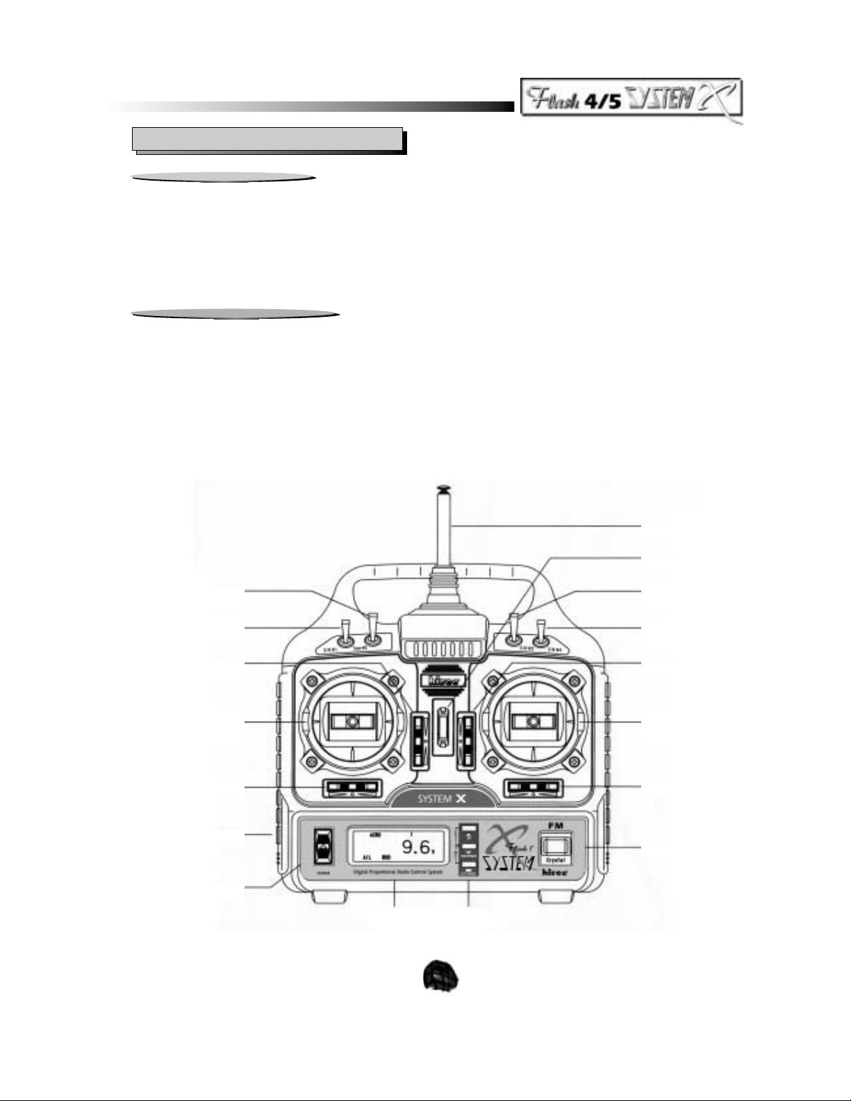
SW#2 TRAINER
SW#1 (3 POSITION)
(FLASH 5 SYSTEM X ONLY)
THROTTLE / ELEVATOR TRIM
THROTTLE / RUDDER(MODE2)
ELEVATOR / RUDDER(MODE1)
RUDDER TRIM
CHARGING JACK
POWER SWITCH
ANTENNA
NECK STRAP EYELET
SW#3 (3POSITION)
(FLASH 5 SYSTEM X ONLY)
SW#4
(FLASH 5 SYSTEM X ONLY)
ELEVATOR / THROTTLE TRIM
AILERON / ELEVATOR(MODE2)
AILERON / THROTTLE(MODE1)
AILERON TRIM
CRYSTAL
LCD DISPLAY INPUT KEY
Page 6
6
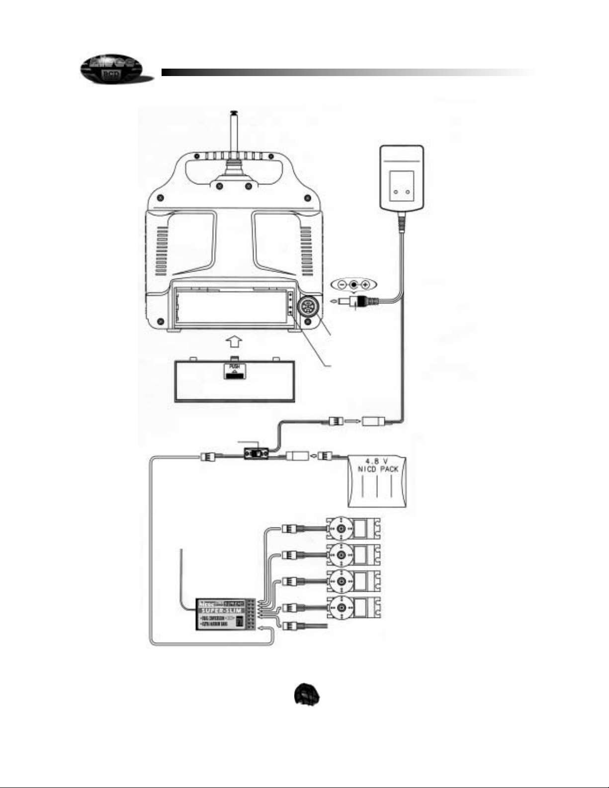
TX CHARGING PLUG
TRAINER JACK
SPARE X-TAL STORAGE
BATTERY
(600mA 8 CELL NICDS)
BATTERY COVER
CHARGING PLUG
RX CHARGING PLUG
SWITCH HARNESS
RETRACT LANDING GEAR
RUDDER
THROTTL
ELEVATO
AILERON
RECEIVER
RECEIVER
ANTENNA
Page 7

Mode & Switch Function Channels
7
4. Digital Trims
Your System X radio features electronic digitally controlled trim keys as opposed to conventional, mechanically operated trim
levers. This digital trim feature allows for very precise trim movements that are just not possible with mechanical trim levers. A
typical radio system with mechanical trim levers may have 20 to 30 trim
clicks available to the pilot for trim purposes, the
System X has 50 trim positions possible. Setting the trims is quite similar to conventional radios with the exception that for each
input, either plus or minus, you will hear a short beep to let you know that a change has been made by the trim key. You may
also hold the trim key down for large amounts of trim movement. Each time you use the trims, the setting will appear on the LCD
screen for a short period, after which the screen will return to Operational Mode display. To review how much trim has been
used, depress the trim key for the desired channel you wish to review and the value will be displayed on the LCD screen. Your
System X system will automatically save the information, even after changing to a different model in memory.
5. System Overview and Menu Defaults
In order to take full advantage of the System X radio programming, you will need to take a few moments to become familiar with
the input keys that make all this possible. The programming input operation requires the following keys and switches on the
transmitter:
1. The LCD display
2. The 3 main input keys (UP, DN/TIMER, CUT/SAVE keys)
3. Rudder (CH4 ) trim key
4. Aileron (CH1) trim key
5. Main Power switch
3. Switch Assignment
The Flash 5 System X is capable of three different flight modes and the switches have different functions in the different flight
modes.
ACRO Mode
Switch 1 Elevator Dual and Exponential rates. 2
Switch 2 Trainer Switch All
Switch 3 3 position Flap or Retract 5
Switch 4 Aileron Dual and Exponential rates 1
GLID Mode
Switch 1 3 position Throttle or Flap in channel 3 3
Switch 2 Trainer Switch All
Switch 3 Flaperon / Camber and Elevator, FLP2 1/5 & 2
Switch 4 Aileron and Elevator Dual and Exponential rates 1 & 2 or 1/5 & 2
GLIDACRO Mode
Switch 1 Elevator Dual and Exponential rates 2
Switch 2 Trainer Switch All
Switch 3 Flap / Spoileron, FLP1 1/5 & 2
Switch 4 Aileron Dual and Exponential rates 1 or 1/5
Page 8

8
The System X has two main menu programs to select from when setting up your model(s) with each menu having separate
methods of access to a particular menu. This prevents the accidental editing or changing of programs in the incorrect
mode .
The first menu you will access is called the
INITIAL MODE menu and is comprised of the following menu choices:
1. Aircraft Mode
2. Stick Mode Configuration (Mode I or Mode II)
3. Flight Timer settings
4. Elevon Mixing activation (on) or deactivation (off) in ACRO mode only
5. V-Tail Mixing activation (on) or deactivation (off)
6. Data Memory Reset (to factory defaults)
INITIAL MODE MENU DEFAULTS
Symbol Function Default
ACRO Aircraft Mode Model 1 and 2
GLIDACRO Sailplane Mode Model 3
GLID Sailplane Mode Model 4 and 5
St Stick Mode Mode II
None Timer 10:0
Elevon Elevon Mixer Off
V-Tail V-Tail Mixer Off
RST AL Data Reset none
It is through this menu that you will begin the process of customizing your radio to suit the needs of your particular aircraft, be it a
glider, sport power or acrobatic type plane. Once you have completed programming for the INITIAL MODE program and have
saved everything in the memory, it is time to access the
MAIN EDIT MODE menu. It is in the MAIN EDIT MODE menu that you
make the basic servo adjustments required to make your plane fly correctly. We will use the same transmitter keys and switches
used in the INITIAL MODE menu. Within the MAIN EDIT MODE program, you will be able to access the following sub-routines:
1. End Point Adjustment (EPA) 2. Exponential Rate Adjustment
3. Dual Rate Adjustment (Flash 5 System X only) 4. Servo reversing
5. FLP 1 in GLIDACRO Mode or FLP 2 in GLID Mode (used with SW # 3)
6. Aileron to Rudder Mixing activation (ON) or deactivation (OFF)
MAIN EDIT MODE MENU DEFAULTS
Symbol Function Default
EPA End Point Adjustment 100% for channels 1,2,3,4,5
EXP Exponential Stick Rates 0% for channels 1,2,4
D/R Dual Rates 100% for channels 1 & 2
NOR Servo Reversing Normal (NOR) for channels 1,2,3,4,5
AIL~RUD Aileron to Rudder Mix Off
Once you have made all of the basic aircraft servo adjustments in preparation for the first flight of your plane, you may proceed
with the fun of flying. Your new System X also provides more enhanced programming with the multiple model memory feature.
Your System X transmitter is capable of storing the aircraft settings for up to 5 aircraft at any given time, regardless of model type.
This is done in the
MODEL SELECT MODE menu, which will be the first item we program into your System X transmitter.
MODEL SELECT MODE MENU DEFAULTS
Symbol Function Default
SL Model Select none
Page 9

9
IV. Programming your System X Radio
1. Model Selection
The System X offers the modeler the ability to store the flight settings for up to five (5) separate models into non-volatile memory.
Even if the main battery pack is removed from the System X transmitter, all memory settings will be retained safely. As a safety
feature, the System X has a separate access procedure to allow you to select each model as you wish for programming or flying.
To make a model selection, perform the following procedure:
2. Initial Mode Programming
As the title indicates, the INITIAL MODE menu is used to define how you wish the transmitter to operate for the desired aircraft
and transmitter style of your preference. You will also get to select which mixing options you wish to employ. This needs to be
defined prior to accessing the MAIN EDIT menu since selections made in the INITIAL MODE affect the programming decisions in
the MAIN EDIT menu. To access the INITIAL MODE menu, it is necessary to have the transmitter turned OFF. Let
s go through
the following procedure to access the INITIAL MODE menu:
1. With the transmitter OFF, depress both the UP and DN/TIMER keys simultaneously.
2. While holding down both keys, turn the transmitter ON.
3. The LCD display should now show the ACRO or GLID symbol plus the model number you have
selected in the Model Selection mode.
If this message does not appear on the LCD screen, turn the power switch OFF and repeat this process, making sure you are
depressing both the UP and DN/TIMER when the transmitter power is applied. Once in this menu, we are ready to begin the
programming process.
a. Aircraft Mode Change
Your Flash System X radio has the ability to tailor itself to the needs of the pilot by changing aircraft modes between a sport
acrobatic type plane, a dedicated glider, or a combination of glider and acrobatic model, such as powered motor glider.
In the acrobatic ACRO mode, you will have all options shown in the INITIAL MODE available to you. Note that should you select
to use the ELEVON or the V-TAIL mixing options, you may use only one or the other at a time. Both ELEVON mixing and V-TAIL
mixing cannot be used simultaneously. Also SW # 3 will provide you a non-proportional channel function normally used for
activating your retractable landing gear. Because this switch is a three-position switch, you may also use this function to actuate
other controls on the aircraft, such a three-position flap setting or bomb release, etc.
In the Glider or GLID mode, you will not have the ELEVON mixing option available to you, however you will have the use of the
three position switches, SW # 3 and SW # 1. In the Glider mode, SW # 1 is a three-position switch giving a preset 0%, 50% and
100% throttle or flap control. Through the 3rd channel. SW # 3 can mix the Aileron (CH 1 and CH 5), and Elevator (CH 2) together
for glide path control of a sailplane as well as adjust flaperons proportionately via the throttle stick. We discuss this specialized
function in the GLIDER PROGRAMMING chapter of this manual.
You may also create a combination of both the ACRO mode and GLIDER mode within the Flash System X radio.
1. With the Transmitter OFF, depress both the DN/TIMER and CUT/SAVE keys.
2. While holding both keys down, turn the transmitter ON.
3. The LCD display will show the
SL symbol.
4. Use the Rudder (ch4) trim key to select the desired model number
5. Press the CUT/SAVE key and two beeps will sound, this
saves the model choice.
6. Turn the transmitter OFF and then back ON again to activate the model selected.
Page 10

10
Page 11

11
In the GLIDACRO mode, ELEVON mixing is not available to you, however V-TAIL mixing is available, as is SW # 3 as a threeposition function switch for mixing Ailerons (CH 1 and CH 5), and Elevator (CH 2). All three channels may be mixed in this mode
to accomplish a number of functions. For example, a sport acrobatic plane may display adverse nose pitching when flaps are
deployed. By mixing elevator with the flap command, the pilot will automatically correct the plane, requiring less work. We will
discuss other possibilities in the ACROBATIC PROGRAMMING chapter of this manual.
Please review the switch assignments for the different model modes on page 7.
To select an alternative model mode, use the following procedure:
b. Stick Mode Change
Your System X radio can be converted to Mode I or Mode II stick styles, regardless of the factory set mode. Mode I has the
Throttle (Ch 3) and Aileron (Ch 1) on the right side stick with Elevator (Ch 2) and Rudder (Ch 4) on the left side stick. Mode II, the
most popular style in the United States, has the Aileron (Ch 1) and Elevator (Ch 2) on the right stick, while Throttle (Ch 3) and
Rudder (Ch 4) are on the left stick of the transmitter.
If you decide to change the transmitter from Mode I to Mode II, or vice versa, the procedure to make this change is as follows:
1. Depress and hold both UP and DN/TIMER keys and turn your transmitter ON.
2. To change model mode style, use the CUT/SAVE key to make selection.
3. Once you make your selection, turn transmitter OFF. Your new selection will appear when the
transmitter is turned back ON.
NOTE: If you have chosen the Mode I control configuration, the following transmitter changes will be necessary. The drawing
below shows where the changes are to be made. Please note that since the drawing shows the back of the transmitter, the
throttle is now on the right side of the picture, and you will want to move it to the left side of the picture.
a. Remove the transmitter battery
b. Move the copper Ratchet piece from (A) on right to (A)
on the left.
c. Add spring tension to (B) on the right side by turning the tension spring screw clockwise.
d. Loosen tension to (B)
on the left side by turning tension spring screw counter-clockwise.
e. Remove the spring limit bracket (C) from the right side and place it on the left side at position (C)
f. Reconnect the transmitter battery
1. Depress and hold both UP and DN/TIMER keys and turn your transmitter ON.
2. Press either the UP or DN/TIMER key until display shows
St , or Stick Mode.
3. To change stick Mode style, use the CUT/SAVE key to make selection.
4. Once you make your selection, turn transmitter OFF. Selection is complete.
TENSION SPRING
TO CLOCKWISE
(B)
(C)
(A)
(A)
RATCHET COPPER
SPRING LIMIT
BRACKET
(C)
(B)
TENSION SPRING
TO CLOCKWISE
Page 12

12
Your conversion from Mode II to Mode I is now complete. Do the reverse of this procedure to change from Mode I to Mode II
style, if necessary.
C. Countdown Timer Feature
Your System X radio is equipped with a built-in timer to alert you to any number of situations, such as low fuel, low receiver
battery or even task completion time. The factory default for the timer is set for ten minutes, (10:0). You may change this to a
maximum timed amount of thirty (30) minutes or a minimum time of one (1) minute. Only whole minutes may be timed. To set
the timer, use the following procedure:
Please note that when you access the timer indicator screen in the Initial Mode menu, it will be displayed as 10:0. There is no 1second read out. Additionally, when you activate the timer during your flight, in the operational mode, the timer will show 9:5.
This is due to the fact that the timer actually starts at 9:59. Since 1-second intervals are not displayed, all you see is 9:5 and the
numbers will then change every 10 seconds.
An audible countdown will beep at each second of the remaining 10 seconds on the timer until the timer reaches: 0. To activate
the timer under normal flight operation, depress the DN/TIMER key once, and the LCD screen will automatically switch from the
transmitter voltage display to the countdown timer and immediately start the countdown sequence in 10-second increments with
the final 10 seconds being audible. You may stop the timer at any time simply by depressing the DN/TIMER key once. To restart
from where you left off, depress the DN/TIMER key again and the countdown will resume. To reset the timer to the original time
and start over, depress the UP key once followed by the DN/TIMER key to restart your
countdown.
d. Mixing Functions, Elevon and V-tail
The System X radio offers you a choice of three pre-programmed, separate mixing functions, two of which, Elevon and V-tail may
be accessed through the Initial Mode menu. The third mixing function is offered from the Main Edit Mode menu. The mixing
functions we will explain here are the V-tail mixer and the Elevon mixer functions. To access either one of these mixing
functions, use the following procedure:
1. Depress and hold both UP and DN/TIMER keys and turn your transmitter ON.
2. Press either the UP or DN/TIMER keys until display shows
10:0 or the timer setting mode.
3. Use the Channel 4 (Rudder) trim key to increase or decrease the timer value. Press the right
side of the trim key to increase time, and the left side of the trim key to decrease the time.
4. When you have the time desired, turn the transmitter OFF, and then back ON. Your timer will
be set and ready to use.
1. Depress and hold both UP and DN/TIMER keys and turn your transmitter ON.
2. Press either the UP or DN/TIMER key until display shows the ELEVON mix or V-TAIL mix
function in the lower right corner of the display
3. Depress the CUT/SAVE key to turn the desired function ON or OFF.
4. When you have selected the function and activated or deactivated the function, turn the
transmitter OFF and then back ON. The LCD display should show the mixer function you
have activated in the lower right corner of the display. If the mixer function was deactivated,
no mixer function is displayed on the screen.
Please note that you may only select one of the two mix options per model. This means that if you have a model with one of
these mixers activated, the other mixer is automatically turned off. The remaining mixing function available to you, AILERON to
RUDDER mixing, is accessed through the Main Edit Mode menu, and will be covered in that section on page 21.
Elevon mixing is only availible in the ACRO model mode via channels 1 and 2.
Page 13

13
When you select the V-TAIL option, and you desire to have the V-tail work from the right side aileron stick, it is necessary to use
the Aileron to Rudder mixing function. Otherwise, the V-tail will work from the rudder stick for turning and the elevator stick for
pitch movement
e. Data Reset Feature
The final option available in the INITIAL MODE menu is called DATA RESET. The message on the LCD screen will show as,
RST AL . This option allows you to reset all of the INITIAL MODE and MAIN EDIT MODE settings for the selected model on
screen to the factory default settings. This allows you to start fresh when programming a new model into memory and you no
longer need the settings for the previous model. To review the factory defaults settings, please see Page 8 of this manual. To
reset the programming data, use the following procedure:
Please note that this procedure affects only the model you are presently working on, and will have no effect on any other model
held in memory.
f. Initial Mode Programming Review
We have now completed the first phase of the transmitter programming routine. Before proceeding to the MAIN EDIT MODE
menu, we need to take a few minutes to verify that the data we input during the INITIAL MODE is exactly what was called for. To
do this, turn the transmitter power ON. The LCD screen should display the following items when the power is turned ON for this
review: In the upper left corner of the display, the word ACRO, GLID or GLIDACRO should appear, depending on which option
you have selected. To the right of this will appear the number 1,2,3,4,or 5, designating which of the 5 aircraft models was
programmed and activated at this time. Just below this will be the transmitter voltage readout, which should be the largest item
on the display. If you have activated one of the three mixing options, the mixing option you have activated will appear on the
bottom right of the display.
Now let
s check the timer to determine that you have the correct countdown time programmed on the display. Press the
DN/TIMER key, and the display will now switch to the countdown timer mode and begin counting down immediately in 10-second
intervals. For example, if you have programmed in 10 minutes, the display will show you 9:5 and within 10 seconds, will change
to 9:4.
It is now time to check out the stick configuration mode. To do this, remove the servos, receiver and receiver battery pack from
the box and set them in front of you. Plug in all the servos in channels 1 through 4 on the receiver.
NOTE: when plugging in the servos and battery switch harness, make sure the black wire always faces down(towards the bottom
of the Super Slim Rx) or towards the
outside on the Supreme or 555 receiver. NEVER FORCE THE CONNECTOR INTO THE
RECEIVER. The plugs are designed to fit smoothly only one way.
Make sure your transmitter is turned ON to prevent random radio signals from being processed by the receiver, which could result
in damage to the servos. Next, plug the battery into the switch harness and the switch harness into the appropriate slot on the
receiver marked
B or BATT . Turn the battery switch ON. Moving the sticks on the transmitter should cause the servos to
move with your stick movement. If you get no response from the servos, or very sluggish response from the servos
1. Make sure you have the correct model you wish to reset selected on the LCD screen.
2. Turn the main transmitter power OFF.
3. Depress and hold both UP and DN/TIMER keys and turn your transmitter ON.
4. Press either the UP or DN/TIMER key until display shows
RST AL .
5. Depress the CUT/SAVE key to reset all programming data to the factory default settings.
6. Turn the transmitter OFF, and then back ON. You may now begin reprogramming a new
model in this program position.
Page 14

14
followed quickly by complete stoppage, your receiver battery may need to be charged. If so, please charge the receiver battery
with the system AC charger for a period of at least 16 hours before proceeding.
Now that you have movement of the servos to the transmitter commands, we will check that you have the correct stick mode
programmed into the transmitter. Move the LEFT stick up and down, and verify that the CHANNEL 3 servo operates with your
command. If so, then you have confirmed that the transmitter is set up for MODE II operation. (MODE II operation is the most
popular mode in the United States. MODE I is popular within Europe and Asia). If you have selected to use MODE I, move the
RIGHT stick up and down and verify that the CHANNEL 3 servo operates with your command. Once you are satisfied with the
correct stick mode for your preference, move both sticks around randomly to confirm that all servos are working for you.
To check that any mixing function you may have programmed is actually engaged, perform the following test:
For ELEVON mixing, move either the Aileron or Elevator stick and see if both the channel 1 and channel 2 servos move at the
same time. If so, you have confirmed ELEVON mixing is active.
For V-TAIL mixing, move either the Elevator or Rudder stick and see if both the Channel 2 and Channel 4 servos are moving at
the same time. If so, you have confirmed V-TAIL mixing is active.
Congratulations! We have successfully completed your INITIAL MODE programming and can safely assume that everything is
normal. We can now proceed with the MAIN EDIT MODE programming routine.
3. Main Edit Mode Programming
In this mode, the modeler can perform all of the necessary servo adjustments required prior to taking the aircraft out on its initial
flight. This includes setting the end points of control, exponential rates, servo reversing, etc. The System X radio allows these
adjustments to be performed quickly and easily in any model. Both the Novice as well as the Expert pilot will easily grasp the
fundamentals of customizing the programs to suit their flying needs. Let
s take a moment to review the MAIN EDIT MODE flow
chart and you will see how the menu selection process works.
Because you will be able to see the servos respond as soon as you input the programming data, it is suggested that you install
the radio gear into the model you wish to set up at this time. If this is not feasible, continue with the servos and receiver set up in
front of you and watch the results of the data input.
To access the MAIN EDIT MODE menu, you will need to exit the INITIAL MODE menu. To do this, simply turn the transmitter
OFF, let the LCD display go blank, and then turn the radio power back ON. The LCD screen should now prominently display the
transmitter voltage. With the Operation Mode active, enter the MAIN EDIT MODE menu using the following procedure:
You should now turn ON the receiver power with servos connected to see the full effect of your programming. Let
s start
programming right now.
a. End Point Adjustment
The End Point Adjustment (EPA) function allows you to determine the amount of travel, or movement; a servo will have from both
sides of the center position. This will ensure that you do not over rotate the servo, risking damage to the control linkage or to the
servo itself. It also allows you to set up control surfaces that are
mild (decreased servo travel) for the novice pilot, or to
1. Turn the radio power switch ON
2. Depress both the UP and DN/TIMER keys simultaneously
3. The LCD display should change to the MAIN EDIT MODE menu and you should see the EPA
function on the screen.
4. To exit this menu at any time, depress both the UP and DN/TIMER keys simultaneously once
again.
Page 15

15
setup extremely sensitive control surfaces for the expert pilot by extending the servo travel range. Adjustment of any one
channel can be adjusted from 0% (no servo movement) to 125% of normal servo travel. Normal servo travel is considered to be
30 degrees each side of center for a total servo range of 60 degrees. The factory default setting for each of the available EPA
s
is 100% of normal servo travel. You may program up to 125% of normal servo travel under EPA.
To enter into the EPA function from the normal power ON mode of the transmitter, simply follow the procedure below:
1. Depress both the UP and DN/TIMER keys simultaneously.
2. The LCD display should change to the MAIN EDIT MODE menu and you should see the EPA
function on the screen.
3. Use the Channel 4 trim key to change channel selection.
4. Use the Channel 1 key to increase or decrease the value of your End Point.
5. To exit this menu at any time, depress both the UP and DN/TIMER keys simultaneously once again.
Page 16

16
Page 17

17
The LCD screen should display the EPA function screen, as well as all 5-channel numbers. Channel 1 should be flashing on the
screen and this tells you that you are ready to adjust the Aileron (channel 1) end points. Now, turn ON your receiver with servos
connected so that you can watch the effect of your adjustment.
To decrease or increase the travel of the aileron servo, move the aileron control stick to the right and hold it there. You may
Page 18

18
The Exponential Rate Adjustment function is effective on channels 1, 2 and 4 only, (ailerons, elevator and rudder). To make
adjustments with EXP, we will use the Channel 4 Trim key to select the desired channel we wish to adjust, and the Channel 1 trim
key to change the value of the EXP adjustment. The key to proper use of exponential knows when you need to have
1. Depress both the UP and DN/TIMER keys simultaneously.
2. The LCD display should change to the MAIN EDIT MODE menu and you should see the EPA
function on the screen.
3. Press the UP key to scroll to the EXP function screen. Channel 1 should be flashing.
4. Use the Channel 4 trim key to select the desired channel.
5. Use the Channel 1 trim key to increase or decrease the value of Exponential.
6. To exit this menu at any time, depress both the UP and DN/TIMER keys simultaneously once again.
b. Exponential Rate Adjustment
Exponential Rate adjustment is the next routine on the menu and this function will allow you to change the control response of the
control sticks from being a linear response to what is known as an increasing response curve, or exponential. An example of how
this feature is commonly used would be the pilot on an extremely responsive acrobatic aircraft using full servo throw travel and
does not need much servo input to control the plane in level flight but wants to take full advantage of its acrobatic capabilities.
Therefore, exponential is programmed such that very little servo response is provided when the control sticks are near centered,
or neutral. As the sticks are moved farther from the neutral point, more servo response is generated at a rate greater than a
straight linear response, allowing for quick and precise maneuvers. Exponential values are available from -100% to +100%.
To access the Exponential Rate Adjustment function from the Operational Mode, follow the procedure below:
NOTE ON ENGINE CUT SWITCH AS USED IN THE ACRO MODE:
The System X will allow the user to program the # 3 channel when used with a glow or gas engine to
cut the throttle and stop the engine.
When adjusting your throttle linkage trim for engine idle, set the digital trim to around 30%. Note that
if the CUT/SAVE button is pressed, the throttle servo trim drops to 0%. This should be equal to
closing down the throttle to stop the engine. Experiment with the linkage to achieve the goal of
having the engine stop when the CUT/SAVE button is pressed.
adjust the travel by depressing Channel 1 trim key, either right to increase the travel, or left to decrease the travel. Do this now,
and watch as the display value shown on the transmitter increases in value and the servo begins to move a longer distance from
center. By decreasing the value shown, the servo should decrease the travel distance from center. To select another channel to
adjust, depress the Channel 4(Rudder) trim key left or right and the display will show which channel you have selected for
adjustment by flashing that channel number on the display. Note that each channel is adjusted using the Channel 1 trim key to
change the value, but you need to move the control stick corresponding to the control you are adjusting. For example, to adjust
the elevator, you will need to move the elevator stick to observe the changes being made
All controls on the System X may be adjusted in the EPA function. If you use a specialized retract servo, you may not be able to
adjust the end points, as this will be controlled by the servo itself, (retract servos are not normally a proportional servo). However,
standard servos will respond to the EPA adjustment. For owners of the Flash 4 System X, Channel 5 will show up on the LCD
screen, but will not have any effect, as the Flash 4 System X does not have a Channel 5 key. Now that you have programmed all
of your end points, you may return to the operational mode for flying by depressing both the UP and DN/TIMER keys
simultaneously. Or, you may move on to the next programming function, known as Exponential Stick Rates.
Page 19

19
1. Depress both the UP and DN/TIMER keys simultaneously.
2. The LCD display should change to the MAIN EDIT MODE menu.
3. Press the UP key to scroll to the D/R function screen.
4. Use the Channel 4 trim key to select the desired channel.
5. Use the Channel 1 trim key to increase or decrease the value of Dual Rates.
6. To exit this menu at any time, depress both the UP and DN/TIMER keys simultaneously once again.
When you have accessed the Dual Rate function, the screen will show D/R at the far left with channels 1 and 2 at the top of the
screen. At this time, channel 1 should be blinking, indicating this channel is ready for dual rate programming, and a value of
100% is shown in the middle of the screen. This is the factory default value and means there is no change in servo response
rates when the dual rate switch is activated.
To select either of the two channels available for programming, use the channel 4 trim key and the other channel indicator will
begin flashing. Next using the channel 1 trim, increase (up to 125%) or decrease, as low as 0% (no movement at all) the servo
movement. Flip the appropriate switch up (see below) to observe the servos decreased (or increased) movement when
c. Dual Rate Adjustment
Dual rates allow the pilot two completely different travel rates of servos travel for greater control versatility of the aircraft. By
programming a second set of servo travel values, (from 0% to 125% of normal servo movement), you can increase or decrease
the aircraft response when moving the sticks, simply by flipping the dual rate switches. The use of dual rates is especially helpful
when becoming accustomed to flying a highly responsive acrobatic aircraft. By programming your second set of servo travel
volumes at a rate considerably lower than normal, you can get the feel for the aircraft at low rates, set the trims and make other
minor adjustments, and then flip to high rates to derive the most from the aircraft. With a little experimentation, you will find the
dual rate feature very useful as your flying skills improve.
The Flash 5 System X comes equipped with two dual rate switches. (Flash 4 System X models do not have a dual rate option).
The aileron dual rate activation switch SW # 4 is located in the upper right hand corner of the transmitter face, and the elevator
dual rate activation switch SW # 1 is located in the upper left corner of the transmitter face. These are the two channels available
for dual rate controls on this radio system.
To program the Dual Rates beginning from the Operational Mode, follow the procedure below:
MODE FUNCTION SWITCH & POSITION
ACRO and GLIDACRO MODE Elevator SW # 1 full UP
Aileron SW # 4 full UP
GLID MODE Elevator and Ailerons SW # 4 full UP
sensitive control response and when you need milder control response. Most pilots need mild response around neutral. The
Channel 1 trim key will adjust the amount of exponential control response to either more sensitive at neutral or less sensitive at
neutral. We do this by placing a value to the PLUS (+) side for increased control response or MINUS (-) value for decreased
control response around neutral.
Repeat this process for all remaining controls that you wish to use exponential rates with. Select the channel you wish to adjust
using the Channel 4 (rudder) trim key. As the feel for exponential response rates is a matter of personal preference, only you, the
pilot, will be able to determine how much, if any, exponential effect you wish to program in for your particular model. The Flash
System X exponential rates become active as soon as you make the adjustments.
The Flash System X exponential rates on the rudder or channel 4 will be active all the time as programmed, however the elevator
and ailerons exponential rates become active as soon as you move the appropriate switch.
Page 20

20
e. GLIDACRO FLP 1 and GLID FLP 2
In the GLID and GLIDACRO model modes the SW # 3 programming screen will show-up here. This option will allow you to
program the amount of movement both in a down position (flaps) or up position (spoilerons) the flaperon function will
accommodate when using the SW # 3 switch. Additionally in the GLID mode you can use the throttle stick to allow proportional
use of the flaperons. To access this screen you must be in either the GLIDACRO or GLID model modes, then
MODE FUNCTION SWITCH & POSITION
ACRO and GLIDACRO MODE Elevator SW # 1 full UP
Aileron SW # 4 full UP
GLID MODE Elevator and Ailerons SW # 4 full UP
Special Note for Flash 4 System X Owners: Because the programming routines are identical between the Flash 4 System X and Flash 5 System X,
the Dual Rate function will appear in the MAIN EDIT MODE menu of the Flash 4 System X radio. However, since there are no dual rate switches on
the Flash 4 System X, this programming function will act as Adjustable Traveling Volume for Aileron and Elevator channels. Simply program in the
percentage of total servo movement using the same procedure as above. One note of caution should be mentioned. It is possible to program 0%
servo travel while in this program. To maintain a suitable safety margin, it is advisable that you not program anything less than 30% total servo
travels.
d. Servo Reversing
Servo reversing is an important function of your System X radio. It allows you to place your servos into the aircraft without regard
to the normal direction of rotation. In other words, if you find that you have installed your elevator servo in such a manner that UP
elevator command results in DOWN elevator instead, you may easily correct this using the Servo Reversing function.
To access the Servo Reversing function from the Operational Mode, follow the procedure below:
1. Depress both the UP and DN/TIMER keys simultaneously.
2. The LCD display should change to the MAIN EDIT MODE menu.
3. Press the UP key to scroll to the Servo Reversing function screen.
4. Use the Channel 4 trim key to select the desired channel.
5. Use the CUT/SAVE key to REVERSE the selected channel.
6. To exit this menu at any time, depress both the UP and DN/TIMER keys simultaneously once again.
The LCD screen will show you the aircraft mode you are in, (ACRO, GLID, Etc), followed by the NOR message, and then by the
channels you may reverse through this function. All 5 channels may be reversed, as you need for each model, independently.
Channel 1 should be flashing on the screen at this time, indicating it is ready for reversing.
To select a channel to affect with servo reversing, use the channel 4 trim key to change channels. The selected channel will flash
continuously for you. To change the direction of the servo, use the CUT/SAVE key to make the change. The LCD screen will
change from NOR to REV, on the right side of the screen, indicating the change has been made. As you may perform this
function with the receiver and servos turned ON, it is possible to watch the change occur immediately on the aircraft. Once you
have programmed all servos to operate in the correct direction, simply depress both the UP and DN/TIMER keys simultaneously
to exit from this function and return to the Operational Mode.
(Note: Many experienced pilots will perform a flight control check prior to each flight they make with every aircraft. Such a flight
check ensures that all flight control surfaces move in the proper direction and the proper amount. This is a good habit to get into
and could help spot a problem on the ground before it becomes a bigger problem in the air!)
programming this feature. By toggling back and forth you can see the results of your programming on the servo movement.
Page 21

21
1. Depress both the UP and DN/TIMER keys simultaneously.
2. The LCD display should change to the MAIN EDIT MODE menu.
3. Press the UP key to scroll to the AIL?RUD Mixer function.
4. Depress the Channel 4 trim key on the left side only and the OFF message will begin to flash.
5. Depress the CUT/SAVE key and the message will now read ON.
6. Depress the Channel 4 trim key on the right side just once.
7. Use the Channel 1 trim key to input a percentage.
8. To exit this menu at any time, depress both the UP and DN/TIMER keys simultaneously once again.
f. Aileron / Rudder Mixing
In the INITIAL MODE menu, we mentioned that there are three, pre-programmed mixing functions available to you in the System
X. Two of these, V-tail mix and Elevon mix, were accessible from the INITIAL MODE menu, and the third mixing function,
Aileron/Rudder mixing, is presented here in the MAIN EDIT MODE menu. Because this mix requires direct input from the
modeler, it is part of the Main Edit Mode. This mixing function is used to provide a linear mix of the rudder to the aileron
command, allowing smooth coordinated turns from your aircraft. Typical aircraft using this mix are sailplanes, larger scale aircraft
and powered planes with very long wingspans and short tail movement.Within this program, the aileron function will be the
master control while the rudder will act as a slave control, meaning that whenever the aileron stick is moved, the rudder will
move with the aileron control in an amount you have programmed. You may override the input of the aileron with the rudder at
any time whenever the rudder stick is used, as the rudder stick input remains independent of the mix.
To access the Aileron/Rudder Mix function from the Operational Mode, follow the procedure below:
If in GLIDACRO:
1. Depress both the UP and DN/TIMER keys simultaneously, the LCD display should change to
the MAIN EDIT MODE menu.
2. Press the UP key to scroll to the FLP 1 screen.
3. With SW # 3
UP , program your percentages as described below,
4. Use the Channel 4 trim key to select the desired channel to program.
5. Use the Channel 1 trim key to input a percentage.
6. The SW # 3 middle position is neutral and non-programmable.
7. Switch the SW # 3 switch to the lower position and program it like you did the up position.
8. To exit this menu at any time, depress both the UP and DN/TIMER keys simultaneously once again.
This will give you two user-preset positions for flaps or spoilerons when the SW # 3 switch is UP and DOWN. The third position is
non-programmable and neutral when the switch is in the MIDDLE position.
If in GLID:
1. Depress both the UP and DN/TIMER keys simultaneously, the LCD display should change to
the MAIN EDIT MODE menu.
2. Press the UP key to scroll to the FLP 2 in GLID screen.
3. In GLID mode with SW # 3
UP program your percentages as described below.
4. Use the Channel 4 trim key to select the desired channel.
5. Use the Channel 1 trim key to input a percentage.
6. Do the same with the SW # 3 middle and down positions.
7. To exit this menu at any time, depress both the UP and DN/TIMER keys simultaneously once again.
This will give you one user preset position when the SW # 3 switch is UP. A flaperon proportional movement mix to the throttle
stick when SW # 3 switch is in the MIDDLE and yet another user preset when the switch is in the DOWN position.
More information on these functions can be found in the GLID and GLIDACRO supplements at the end of this manual.
Page 22

22
g. GLID Mode or Glider Mode Programming s Supplement
In this chapter, we will take you through the specialized programs used in many glider and specialty models. The Flash 5 System
X is versatile and easy to program for these model types. For the basic programming, please review Chapter IV, especially the VTAIL MIXING function. Many gliders utilize these functions, depending on the design. Note that the ELEVON MIXING function is
not available to you in the Glider mode.
In the MAIN EDIT MODE, we have the one of the biggest programming change for gliders, this being the Flaperon mix function.
The three-position switch, SW # 3, controls Flaperon mix. With the Flaperon Mix, you have the ability to operate a sailplane
utilizing the ailerons as flaps, mixed in with the elevator to prevent the plane from pitching upwards when the flaps are deployed.
Note that this set up utilizes two servos for the ailerons, (channel 1 and channel 5), and one servo for elevator.
To access this function, first plug the right wing aileron servo in channel 1 of the receiver and left wing aileron servo into channel 5
of the receiver. The elevator servo is plugged into channel 2 of the receiver. In the MAIN EDIT MODE menu, you will find a
function screen showing
FLP2 to the right of the screen, and channel 1 is blinking. This indicates the function is activated and
ready for programming. Using the Channel 1 trim key, you may change the value shown on the display to any positive or
negative value. Doing so while the receiver system is turned ON will show you how this adjustment is working for you as the
aileron servo moves with a change in the value. You move the aileron upward or downward as you wish. For this exercise, we
will program in flaperons to slow the plane for landing.
After accessing the FLP2 screen in the MAIN EDIT MODE, move the three-position switch, SW # 3, to the lower position. Let
s
change the value shown on the screen to 50% for the ailerons. With the channel 1 flashing adjust the channel 1 trim on the right
side to read 50%. Select channel 2 by pressing the Channel 4 trim key, right side only. The number 2 should be blinking at you.
Let
s change this value to 25%. Once again, use the Channel 4 trim key to select channel 5, and program this value to
The LCD screen will show you the aircraft mode you are in,(ACRO, GLID, Etc), as well as the AIL RUD mix message in the
lower left of the LCD screen. The RUD message will be seen flashing in the lower left corner with an OFF message directly
above it. Depress the Channel 4 (Rudder) trim key on the left side only and the OFF message will begin to flash. Now, press the
CUT/SAVE key and the message will now read
ON . This means you have activated the Aileron/Rudder mix function.
To begin programming the mix function, depress the channel 4 trim switch on the right side just once. The RUD message will
begin flashing with a value of 0% showing on the right side of the screen. You may change the direction and amount of mix the
rudder will provide when ailerons are used by changing the value shown on the screen. Use the Channel 1 trim switch to
increase or decrease the value of your mixing function. A positive value (+), shown as NOR on the screen by pressing the left
side of the ch. 1 trim switch will increase the amount of rudder movement mixed in with the ailerons, while a negative value, (-)
shown as REV on the screen by pressing the right side of the ch. 1 trim switch will move the rudder in the opposite direction of the
ailerons. Unless there is a special effect desired from moving the rudder in the opposite direction of the ailerons, this would not
be normal. However, due to the effect of servo reversing combined with the individual set up of the plane, it may be necessary to
use a negative value in order to get the correct directional movement. It is for this reason both negatives and positive values are
provided. Because you may observe the effect of your programming while the receiver is turned on, it is
recommended that you set up this program after the radio system have been installed in your aircraft with flight control surfaces
hooked up. To exit this function, depress both the UP and DN/TIMER keys simultaneously and you will return to the Operational
Mode.
There is no set amount or value we can recommend for you to begin with when using the Aileron/Rudder mix function, due to
variety of aircraft which may benefit from this mixing option, as well as the personal taste of each pilot. The idea, however, is to
mix enough rudder control movement into the aileron movement such that the aircraft makes smooth, coordinated turns in flight.
This may take some time to achieve, but the result is well worth the effort.
Page 23

23
h. GLID ACRO Mode or Combination Aerobatic Glider Supplement
The combination GLIDACRO mode allows all the program functions of the ACRO mode set-up as well as the Flaperon mode
switch, which uses SW # 3. Setting up your aircraft in the GLIDACRO mode is similar in routine to the ACRO model, using all the
functions available to you in the INITIAL MODE menu and the MAIN EDIT MODE menu. The main difference is the option to
utilize a two-servo aileron set up, allowing the use of flaperons. (Note: If you decide to utilize this option, SW # 3 will be used for
flaperon operation and cannot be used to operate Channel 5 retractable landing gear.). The Flaperon mode allows you to preset
the position of the flaps for getting the most wing lift during launch or powered flight using the programmable SW # 3 three
position switch.
In the middle position, no presets are programmed into the Flash 5 System X and this switch position is neutral. In the lower
position, you may program a positive or negative value to the flaps. As a negative value, the flaps can be reflexed upwards
allowing a plane to travel at higher speeds as an advantage to its modern airfoil, (such as the SD 7037 airfoil). In the upper
position, you can have the flaps cambered downward to increase the lift for enhanced thermal capability. This is the example we
will program at this time. Place the SW # 3 switch into the lower position. Use the Channel 1 trim switch to change the value to a
negative number. This should move the flap/aileron upward to a reflexed position. Note that you do not need a lot of reflex to get
a large change in the airfoil, 1/16 inch is a good place to begin. Now, flip the switch to the up position, and program a positive
value for the camber setting. Again, this does not require much movement, and 1/8 inch is a good place to begin. The center
position of the three-way switch will remain unchanged. For actual flying, use the reflex to get the aircraft increase its speed
without losing the glide ratio. On a powered aircraft, the reflex position allows high-speed flight under power to enhance the
acrobatic capability or just achieve more efficient speed under power. Use the camber position to launch higher, and to also
assist with thermal flight, whether as a glider or powered model.Channel 3, throttle, is used for operating the normal throttle
function and can be applied to gas powered or electric powered models. The throttle remains a fully proportional channel in this
mode.
This completes the Flash System X programming manual. You have covered a lot of information and now have the ability to set
up and program quickly and easily. We hope you enjoy your Flash System X and hope that using your Flash System X makes
flying a real pleasure for you!
match Channel 1 at 50%. What you just did was program both ailerons to move downward 50% of their travel, the flaps to move
50% and the elevator to 25% of its travel. Now by moving the SW # 3 switch to the middle position and programming channel 1,2
and 5 as we did previously we will get a proportional flaperon mix that can be adjusted with the throttle stick. Now, move the
three-position switch to the upper position. We will now program in new values of 90% aileron, 45% elevator and 90% Channel 5.
What you have accomplished is setting the three position switch to provide you with three different preset control positions to
allow you to perform normal flight, a preset slowed approach speed, and lastly, maximum flaps down control with elevator
compensation for landing. Merely flip the three-position switch to access your desired flaperon position! (Note that all aircraft are
different in the way they respond to flaps being deployed during flight. The mixing values given are examples only, and do not
represent real values that should be used. Actual flight-testing is necessary to derive the best possible combination of flaps,
ailerons and elevator compensation for any given aircraft).
Lastly, we will program SW # 1, a three-position switch, to handle your motor control, as might be seen on electric powered
sailplanes. Using either a standard servo or an electronic speed controller, you may program SW # 1 to provide you with no
motor power, (OFF), 50% power and 100% power settings. The amount can be programmed using the servo or ESC to
determine the exact power setting. SW # 1 will position a servo at full counter-clockwise position, neutral position and full
clockwise position with the flick of the switch. The values of SW # 1 cannot be programmed within the Flash 5 System X menu.
(Note: Do not program your electric throttle settings with a propeller mounted to your motor. This could cause serious damage or
injury.)
 Loading...