

Page 1

OPERATION MANUAL Ver 1.0
www.hitecrcd.com
Page 2

TABLE OF CONTENTS
SECTION 1
Introduction ......................................................................................................................................................................... 3
Warnings and Safety Instructions ................................................................................................................................ 3
Features and Specications ...........................................................................................................................................4
Items Required to Ready This Model for Flight ....................................................................................................... 4
Parts Layout and Listing ..................................................................................................................................................4
SECTION 2
Assembly Instructions ...................................................................................................................................................... 5
Tools Required for Assembly .................................................................................................................................... 5
Step 1: Main Landing Gear Assembly ....................................................................................................................5
Step 2: Horizontal Stabilizer Assembly .................................................................................................................5
Step 3: Vertical Stabilizer Assembly ....................................................................................................................... 5
Step 4: Connecting the Elevator Control Arm Linkage ................................................................................... 5
Step 5: Attaching the Rudder ................................................................................................................................... 6
Step 6: Connecting the Rudder Control Arm Linkage.....................................................................................6
Step 7: Connecting the Tail Wheel .......................................................................................................................... 6
Step 8: Main Wing Assembly .................................................................................................................................... 6
Step 9: Propeller Hub and Spinner Assembly.....................................................................................................7
Step 10: Receiver and Battery Installation ........................................................................................................... 7
Step 11: Centering the Control Surfaces .............................................................................................................. 7
Step 12: Balancing Your Model ................................................................................................................................ 8
SECTION 3
Preparing for Flight ........................................................................................................................................................... 8
• Speed Control Operation .....................................................................................................................................8
• Flying Your Plane ..................................................................................................................................................... 8
SECTION 4
Spare Parts ........................................................................................................................................................................... 9
Service and Support ...................................................................................................................................................... 10
Warranty ............................................................................................................................................................................. 10
2
Page 3

SECTION 1
INTRODUCTION
Thank you for purchasing the Weekender Extra 300S radio controlled model. The Extra 300S is the perfect answer for
the novice pilot looking to expand into the world of aerobatic ight. Built with a pre-painted, durable EPO airframe and
featuring a powerful brushless motor, the Extra 300S promises hours of weekend high-ying fun!
Warning, Caution, Tip and Note Boxes
The Weekender Extra 300S is a radio control model plane designed for novice pilots over the age of 14. Improper assembly or user negligence can lead to serious injury and/or property damage to yourself or other persons.
Weekender is not responsible for any damages or injuries caused by the user’s negligence or improper assembly of the model. Be sure to read the instruction manual thoroughly before assembly and ying.
Safety is of the utmost importance when ying any model aircraft. Third party insurance is mandatory. If you
join a model club or association, suitable coverage will usually be available through the organization. It is
your personal responsibility to ensure that your insurance is adequate (i.e. that its coverage includes powered model aircraft). Always y in such a way that you do not endanger yourself or others. Bear in mind that
even the best RC systems are subject to outside interference. No matter how many years of accident-free
ying you have, there is always the possibility of an unforeseen problem or error that can cause an accident.
Make it your job to keep your models and your radio control system in perfect operating condition at all
times. Check and observe the correct charging procedure for the batteries you are using.
Before every ight, check that the wings and the tail panels are attached and rmly seated. Also check
to make sure that each control surface is operating correctly.
Warning: Be sure to read this section for your own safety.
Caution: Be sure to read this section to prevent accidents
and damage to your model.
Tip: This section will help you maximize the performance
of your model.
Note: This section will provide more detailed explanations.
Flying Your Aircraft
• You should only y at an ocial model aireld.
• Check that other pilots and spectators are positioned safely before ying your model.
• Wait for other pilots to land their models if they are ying already.
• Do not y the plane behind yourself or others.
• Do not y under the inuence of alcohol or drugs or if you are feeling ill.
• Do not y during thunderstorms or high wind.
• Do not y in an area where people are gathered or near tall buildings.
• Do not y near streets or where vehicles or trains pass by.
• Do not y near explosive materials.
• Do not y near power lines or transmission towers.
• Be sure to do pre-ight safety checks of the model before ying.
• Always remember that the pilot is responsible for any outcome that may occur during the ight.
3
Page 4
FEATURES AND SPECIFICATIONS
Features
• Durable pre-painted EPO airframe can easily be
assembled in less than 45 minutes
• Powerful preinstalled brushless outrunner motor and
50Amp ESC gives the Extra 300S plenty of power for
aerobatic ight
• Preinstalled 17 gram micro servos
• Removable cowl for ease of motor and ESC access
• 8 Minute + runtimes when used with recommended
battery
Speci cations
• Wingspan: 47.2 in (1200 mm)
• Length: 42.5 in (1088 mm)
• Weight: 3.1 lb (1400 g)
• Wing Area: 418 sq in (26.97 dm
• Wing Loading: 17.1 oz/sq ft (52.1 g/dm2)
• Assembly Time: <45 minutes
2
)
ITEMS REQUIRED TO READY THIS MODEL FOR FLIGHT
The Weekender Extra 300S is a Plug and Play (P2GO) type model that requires additional items for operation. The items
listed below are needed to y.
• 4-Channel Radio and Receiver
• 3 ~ 4S, 11.1 ~ 14.4V, 2200 ~ 2500mAh LiPo Battery
• Charger Suitable for the Battery Above
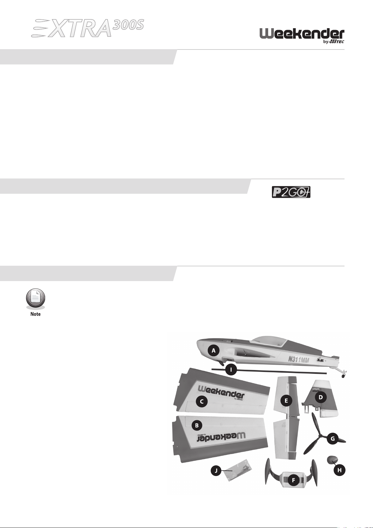
PARTS LAYOUT AND LISTING
Note: Before assembly, it is important that you remove the parts from the packaging and check to make sure
that all the parts are included and that they are in good condition.
A. Fuselage Assembly (includes installed motor & ESC)
B. Left Wing
C. Right Wing
D. Vertical Stabilizer Assembly
E. Horizontal Stabilizer Assembly
F. Landing Gear Assembly
G. Propeller
H. Hub and Spinner Assembly
I. 8 x 686 mm Carbon Fiber Spar Tube
J. Small Parts Package, Includes:
i. 4x 3.0 x 15 mm Landing Gear Screws
ii. 1x 4.0 x 40 mm Machine Screw
iii. 2x 2.6 x 12 mm Horizontal
Stabilizer Screws
iv. 2x Tail Wheel Control Springs
v. 2x Control Linkages
(Rudder and Elevator)
vi. 2x 4.0 x 75 mm Machine Screws
for Wing
4
Page 5

SECTION 2
ASSEMBLY INSTRUCTIONS
Before Assembling the Extra 300S
Keep in mind when assembling and ying the Extra 300S, that radio control model airplanes may cause injury
or property damage when improperly own or mishandled. Always follow the warnings written in the instruction manual. Improper usage could lead to damage and/or failure of the electronic equipment. Be sure to read
this instruction manual in its entirety before assembling and ying this model.
Tools Required for Assembly
•#1PhillipsHeadScrewdriver•1.5mmHexHeadScrewdriver•13mmWrench
STEP 1
Step 1: Main Landing Gear Assembly
Usinga#1Phillipsheadscrewdriverandthefour
3.0 x 15 mm screws, attach the main landing gear
to the fuselage.
STEP 3
STEP 2
Step 2: Horizontal Stabilizer Assembly
With the control horn facing down, slide the
horizontal stabilizer into place and attach to the
fuselage with the 4.0 x 40 mm machine screw.
STEP 4
Step 3: Vertical Stabilizer Assembly
Gently slide the vertical stabilizer into the two slots
cut into the fuselage and lock it into place using
the two 2.6 x 12 mm screws.
Step 4: Connecting the Elevator Control Arm Linkage
Take one of the control linkages and slide the Z bend
through the middle hole of the elevator control horn.
Slide the other end into the swivel on the servo. Tighten
the screw just enough to hold the wire in position.
5
Page 6

ASSEMBLY INSTRUCTIONS (cont.)
STEP 5
Step 5: Attaching the Rudder
Holding the top of the vertical stabilizer, snap the
rudder into place ensuring that it moves freely on
the hinges.
STEP 7
STEP 6
Step 6: Connecting the Rudder Control Arm Linkage
Take the remaining control linkage and slide the Z bend
through the middle hole of the rudder control horn.
Slide the other end into the swivel on the servo. Tighten
the screw just enough to hold the wire in position.
Step 7: Connecting the Tail Wheel
Take the two springs included in the small parts package
and insert the Z bend side into the control horns on the rudder. Then slide the straight end into the swivel barrels. Once
both sides are installed, line up the rudder and tail wheel in
the center position. Now tighten the two screws. We recommend applying a medium strength thread locker to the
screws to prevent them from working loose.
STEP 8
Step 8: Main Wing Assembly
Insert the 8 x 686 mm carbon ber spar tube into one of the wing halves. Slide the wing half into the fuselage making
sure to guide the servo lead through the hole in the center. Holding the installed wing halve, gently slide the other half
onto the spar tube, again making sure to guide the servo lead through the hole in the center. Insert the two 4.0 x 75 mm
machined wing retainer screws though the holes in the fuselage. Tighten until snug.
The screws should slide easily through the holes, if not, make sure the wings are fully seated and together.
Do not over tighten the screws, doing so could damage the plane.
6
Page 7

ASSEMBLY INSTRUCTIONS (cont.)
STEP 9
Step 9: Propeller Hub and Spinner Assembly
Take the propeller hub and slide it through the base of the spinner assembly, then slide the propeller on the hub and
spinner base. Install the washer and nut, do not tighten. Slide this assembly onto the motor shaft and tighten the nut.
Place the spinner over the propeller and attach with the supplied screw.
Once tightened, the distance between the cowl and spinner should be about 4 mm. If it is too close to the
cowl, damage may occur.
STEP 10
STEP 11
Step 10: Receiver and Battery Installation
Install the receiver into the fuselage and plug in the servo
leads. The servo leads are numbered to the corresponding
receiver channel. If using a 4-channel receiver, you will need
a 6-inch Y extension for the aileron servos. Install the battery
into the cavity in the front section of the fuselage as shown
above.
Step 11: Centering the Control Surfaces
With the throttle stick in the lowest (o ) position, plug in the
battery to power up your model. Now set the sticks to their
neutral position and center the control surface on the airplane.
Using a 1.5 mm hex head screwdriver, tighten the grub screws
against the linkages. We recommend applying a medium
strength thread locker to the screws to prevent them from
working loose.
7
Page 8

ASSEMBLY INSTRUCTIONS (cont.)
STEP 12
76 ~ 86 mm
Step 12: Balancing Your Model
Check the center of gravity (CG) on your model by
balancing it on your ngers. The CG should be about
3 ~ 3.4 inches (76 ~ 86 mm) behind the leading
edge of the model as shown below. You can adjust
the CG by moving the battery forward or backwards.
SECTION 3
PREPARING FOR FLIGHT
Speed Control Operation
The ESC is set for optimal performance at the factory and should not be changed. Before connecting the battery, make
sure the throttle is in the lowest (o ) position. If the throttle is not in the lowest, o position, the speed control will not
initialize. If this happens, you will need to disconnect the battery and repeat the initialization sequence.
Flying Your Plane
Before taking o , perform a radio range check and make sure all your control surfaces are operating in the proper direction. Take o into the wind and climb to 50 feet to begin your trim out procedures. Once trimmed out, feel free to test the
performance of the plane by performing a variety of aerobatic maneuvers.
8
Page 9

SECTION 4
SPARE PARTS
61020
Fuselage
61023
Vertical Stabilizer
61026
61021
Main Wings
61024
Cowling
61027
61022
Horizontal Stabilizer
61025
Main Landing Gear
61028
Wheel Covers
61029
Tail Landing Gear
61032
Controlling Linkage Steel Wire
61035
Main Wheels
61030
Spinner
61033
Tail Wheel Springs
61036
Fixing Screws for Main Wheels
61031
Propeller Connecting Shaft
61034
Screws Package
50A Brushless ESC
Brushless Motor D3720-630Kv
9
Page 10

SERVICE AND SUPPORT
Weekender by Hitec Customer Service
Help is available from Hitec RCD USA, Inc. Customer Service through phone support: (858) 748-6948 and e-mail:
service@hitecrcd.com. Our oce is generally open Monday through Friday, 8:00 AM to 4:30 PM PST. These hours and
days may vary by season. Every attempt is made to answer all incoming service calls. Should you get our voice mail,
please leave your name and number and a sta member will return your call.
WARRANTY
LIMITED WARRANTY
Weekender by Hitec guarantees the component parts in this kit to be free from defects in both materials and workmanship that exist at the time of purchase for a period of 90 days from the date of purchase. If any component part fails to
function because of defects in materials or workmanship during this period, the manufacturer’s obligations are limited, at
its discretion, to either, repair or replace the defective part.
This warranty does not cover any component part that has been damaged through use, modication, misuse, abuse, accident or neglect; nor does it cover normal wear and tear. Additionally, this warranty is void if the component part has been
altered or modied or repaired by anyone other than Hitec RCD USA, Inc. or its authorized agents.
Hitec RCD USA, Inc. is not responsible for loss of use of the Weekender by Hitec model, or other incidental or consequential damages. Under no circumstances shall the Manufacturer or any of its representatives be held liable for injury
to persons or property damage resulting from the assembly of the product or from the use of the nal user assembled
product. Furthermore, no liability shall be attached to Weekender by Hitec or Hitec RCD USA, Inc. from the use of the nal
assembled product because: the product operates and is controlled by way of remote radio frequency; and outside radio
frequencies may interfere with the product frequency, causing loss of control. Because an out-of-control model has the
potential to cause personal injury and property damage, Weekender by Hitec or Hitec RCD USA, Inc. cannot be held liable
for personal injury or property damage caused by the use or misuse of Weekender by Hitec model products. By the act of
using the user-assembled products, the user accepts all resulting liability. Some states do not allow exclusion of incidental or consequential damages, so the above limitations and exclusion may not apply to you.
Weekender by Hitec and Hitec RCD USA, Inc. hereby exclude any and all express warranties not specically stated herein
and all implied warranties of merchantability and tness for a particular purpose. There are no warranties which extend
beyond the description of the warranties contained within this document.
What to Return
Return only the component part that is defective in materials or workmanship. Please pack the unit carefully and insure
it, as this warranty does not cover loss or damage in transit.
Hitec RCD USA, Inc.
12115 Paine St.
Poway CA, 92064
(858) 748-6948
10
Page 11

NOTES
11
Page 12

www.hitecrcd.com
 Loading...