

Page 1

Page 2

Page 3

TABLE OF CONTENTS
Introduction
Table of Contents
What’s New?
Projuct Support
Safety Information
Warnings
Hitec 2.4GHz System Set-up
2.4GHz Module Features
Optima Series Receiver Features
Set-up and Use
Range Check Function
Scanmode Set-up
Failsafe
Telemetry System
SPC(Supplementary Power Connection) System
Charging the Eclipse 7 Ni-Mh Batteries
Operating With A Trainer Cord
Other Adjustments
Adjustable length control sticks
Stick lever tension adjustment
Throttle ratchet change
Changing the Eclipse 7 transmitter’s mode
Factory Service Repair Information
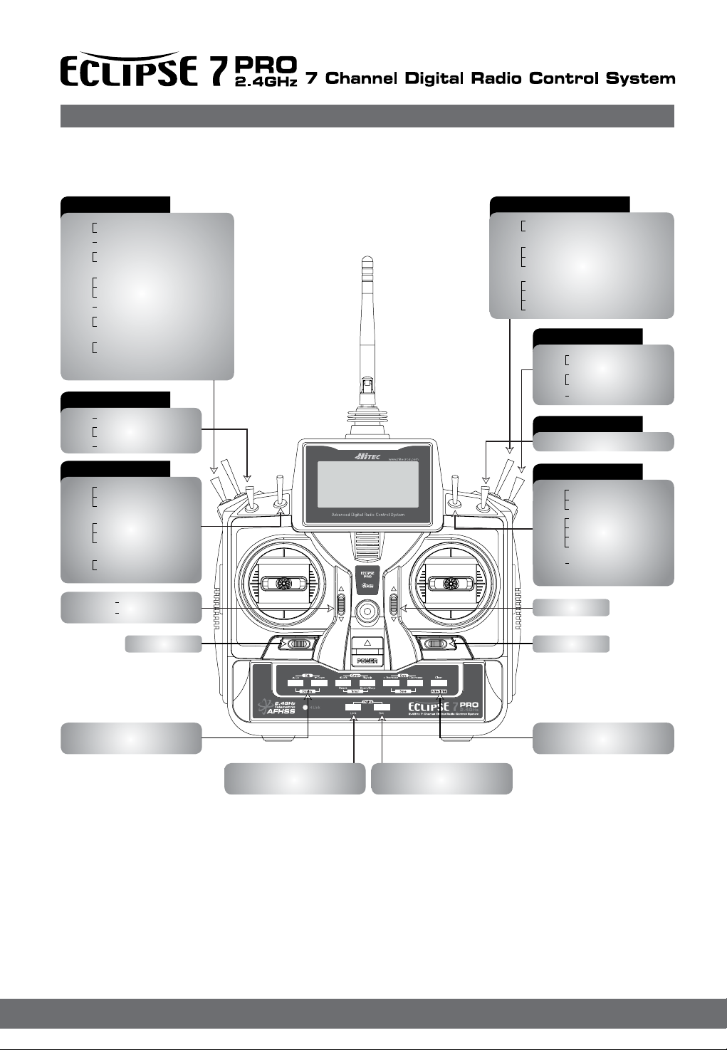
Eclipse 7 Controls and Switch Assignments
Mode II
Transmitter Input Buttons
Receiver - Servo Connection List
Warning Displays
Model Setup Functions
MODL - Model Select
VER - Version
REST - Data Reset
TIME -Timer Function Setup
COPY - Copy Model
ACRO, HELI, GLID - Model Type Select
Wing & Swashplate Type Selection
Model Name
MODE - Mode 1,2,3,4, Changeable
Telementry Display Function
AIRCRAFT (ACRO) MENU FUNCTIONS
Simple Transmitter Setup Aerobatic Airplane (ACRO)
Eclipse 7 Pro Aircraft Controls
and Switch Assignments 1
Airplane Model Function Descriptions
EPA - End Point Adjust
D/R - Dual Rates
EXP - Exponential
FLT.C - Flight Condition Menu
STRM - Subtrim Settings
REV - Servo Reversing
T.CUT - Throttle Cut(Engine Shut off)Function
PMX1 to PMX5 - Programmable Mixes
1, 2, 3, 4, & 5
LAND - Landing Function
FLPT - Flap Trim Function
E->F - Elevator Flap Mixing
A->R - Aileron Rudder Mixing
ELVN - Elevon Mixing
VTAL - V-Tail Mixing
FLPN - Flaperon Mixing
AILV - Ailevator (2Elevon Aileron Mixing)
MX.SS - Mix Switch Select
Aircraft Flight Trimming Chart
Glider (GLID) Menu Functions
2
Eclipse 7 Glider Controls
and Switch Assignments
2
3
6
12
12
12
13
13
Competition Glider Quick Setup Instructions
Glider Model Function Descriptions
ADIF - Aileron Differential
VTAL - V-Tail Programming
E->F - Elevator Flap mixing
A->R - Aileron Rudder mixing
F->A - Flap Aileron mixing
F->E - Flap Elevator mixing
CROW - Crow mixing (airbrakes)
S.TM1, 2 - Speed Flap Trim offsets 1, 2
AIL.T - Aileron trim
A->F - Aileron Flap mixing (4WNG only)
DFL.T - Dual Flap Trim (4WNG only)
MX.SS - Mix Switch Select
SAILPLANE TRIMMING CHART
Eclipse 7 Helicopter (HELI) Programming
Eclipse 7 Helicopter Controls
and Switch Assignments
Helicopter Setup Instructions
Menu Descriptions - Helicopter
14
16
16
18
19
19
19
19
20
20
20
21
22
22
22
Flight Conditions
R->T - Rudder Throttle Mixing
GYRO - Gyro settings
HOLD - Throttle Hold
THCV - Throttle Curve
PTCV - Pitch Curve
RVMX - Revolution mixing
SWAH - Swashplate adjust (120’,140’, 180’)
MX.SS - Mix Switch Select
Hovering Throttle Adjustment Knob
Hovering Pitch Adjustment Knob
Helicopter Flight Trimming Chart
Adjust Hovering Pitch and
Hovering Throttle
24
24
30
29
29
29
32
33
33
34
34
34
35
35
36
36
37
37
38
39
39
40
42
43
45
47
48
48
48
48
48
48
49
50
50
50
51
52
53
56
54
56
59
59
59
59
60
60
60
62
61
61
61
61
62
62
Page 4

What’s New?
Many of you have owned or used earlier model Hitec transmitters. Here are four “new” Hitec transmitter features that set the
Eclipse 7 Pro apart from all other Hitec products.
1. Signal Protocol
Using Hitecs AFHSS 2.4GHz module to link with Hitec Optima AFHSS 2.4GHz receivers.
2. Gimbals
Feel the silky smooth action of the new four ball bearing supported gimbals in the Eclipse 7 Pro. These new gimbals were created to give you the smoothest action demanded by the highest performance aircraft.
3. Switch Assignments
During the model programming steps you will be asked to select what stick, switch or slider controls the features you want to
use with your model. This gives you unlimited exibility to choose the most comfortable and practical way for you to use the
Eclipse 7 Pro..
4. Channel and Control Assignments
The Eclipse 7 Pro will automatically select the channel and control assignments based on the model you have. There is the
option to change them if you wish, allowing you a wider choice of receivers that can be used with the Eclipse 7 Pro..
Safety Information
Flying models can be dangerous if proper safety precautions are not followed. Here are a few critical safety
suggestions to keep you and others safe.
Are you experienced?
Flying models is not an intuitive process. Most accomplished model pilots were taught by another modeler. We encourage
you to seek help during your early ight experiences and if required, during the building and gear installation process. Unlike
some other hobbies, model airplane ying has evolved into a social event. There are approximately 2,500 model aircraft clubs
in America. Friendship and help could be right around the corner. Ask your local hobby shop about clubs in your area.
Where to Fly
Having enough land for your own model airport is rare. Most of us y at club administrated model elds. The local ball eld
can be tempting but rarely has the space needed and your liability is high should you damage property or hurt an innocent
person. We recommend you y at a sanctioned model aircraft eld.
Join the AMA
In America, the Academy of Model Aeronautics (AMA) is an organization of model enthusiasts that provide resources and
insurance to modelers. The AMA also lobbies the Government concerning legislation that impact modelers.
Visit their web site for more information, www.modelaircraft.org.
Academy of Model Aeronautics
5151 East Memorial Drive
Muncie, Indiana 47302
Toll Free : 800 435-9262
Fundamental Guidelines for Safe Flying
1. Don’t y over people or personal property.
2. Make sure you do a range and pre-ight check on your aircraft.
3. Check for others ying on your frequency. (No need with 2.4GHz)
4. Know your batteries condition. Keep them charged.
5. The equipment we use in the R/C hobby is sensitive electronic gear. Have receivers checked after a crash before using
them in another aircraft.
6. Use the Fail-Safe function in AFHSS mode to lower the throttle in case of a signal “lock-out”.
7. Don’t y alone.
2
Page 5

Hitec 2.4GHz System Set-up
TRAINER
2.4GHz Module Features
The following contains the complete instructions on how to use the Optima 2.4GHz series receivers and Eclipse 7 Pro set for a
trouble free 2.4GHz signal. We encourage you to review this information before using these products.
1. Dual Blue and Red Status indicator LED’s
Indicates the set-up process codes and use status..
2. Function Button
Used for Linking(ID -Setting) the Eclipse 7 Pro to a receiver, entering the power down mode for range checks and the Nomal /
Scan Mode set-up.
3. Sensor Data Output and System Upgrade Connector Port
A 3 pin servo plug connector port is featured on back side of Eclipse 7 Pro . Using the HPP-22 PC interface accessory this
port serves to facilitate upgrading the devices software and downloading information from Optima 7,9 receiver if using
optional onboard sensor station..
2. Function Button
1. LED
3. Sensor Date Output &
System Update Port
3
Page 6
Hitec 2.4GHz System Set-up
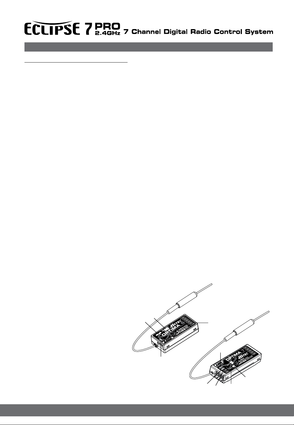
Optima Series Receiver Features
As of this writing, there are three Optima 2.4GHz receivers that are compatible with the Eclipse 7 Pro .The Optima 6, Optima 7
and the Optima 9 channel products are loaded with a variety of functions that are sure to deliver a satisfying R/C experience.
1. Telemetry Sensor and System Port
A three pin servo plug connector port is featured on the Optima 7 and 9 ch receivers. Using the HPP-22 PC interface acces
sory this port serves to facilitate upgrading the devices software and interfacing the optional onboard sensor station.
2. Function Button
Used for Linking(ID-Setting) the receiver to a Eclipse 7 Pro , entering Fail-Safe / Hold mode setup function.
3. Dual LED Status Indicator
Indicates the set-up process codes and use status
4. SPC Supplementary Power Connection
Power the Optima receiver function with up to a 35V. motor battery. Details about the SPC system can be found on page 9.
5. Channel Output and Battery Input Ports
The ports for battery power, servos, gyros and other accessories are located at each end of the streamlined Optima receivers.
6. Jumpers
The jumper is installed at the factory and is used when the receiver is powered by an electronic speed control, a commercially
available B.E.C. (battery eliminator circuit), dedicated 4.8 to 6V. NiMH battery pack, or *2S Li-Po/Io/Fe batteries. The jumper is
removed when the receiver is powered using the SPC feature as described in more detail on page 9.
(*Verify your servos are rated for use with these higher voltage batteries or use a regulator.)
Normal / Scan Mode Selectable
Select between two operational signal types. See page 6 for details.
FAIL-SAFE Option
Servos and other accessories may be programmed with a FAIL-SAFE point in the event power to the receiver is interrupted.
See page 7 for details..
Onboard Receiver Battery Warnings
Know when your on-board battery is low with direct telemetry feedback to your transmitter. See page 8 for details.
1
1. Function Button
2. Dual LED Status Indicator
3. Channel Output and Battery Input Ports
4. SPC (Supplementary Power Connection)
5. Telemetry Sensor and System Port
2
4
3
5
1
4
2
3
4
Page 7

Hitec 2.4GHz System Set-up
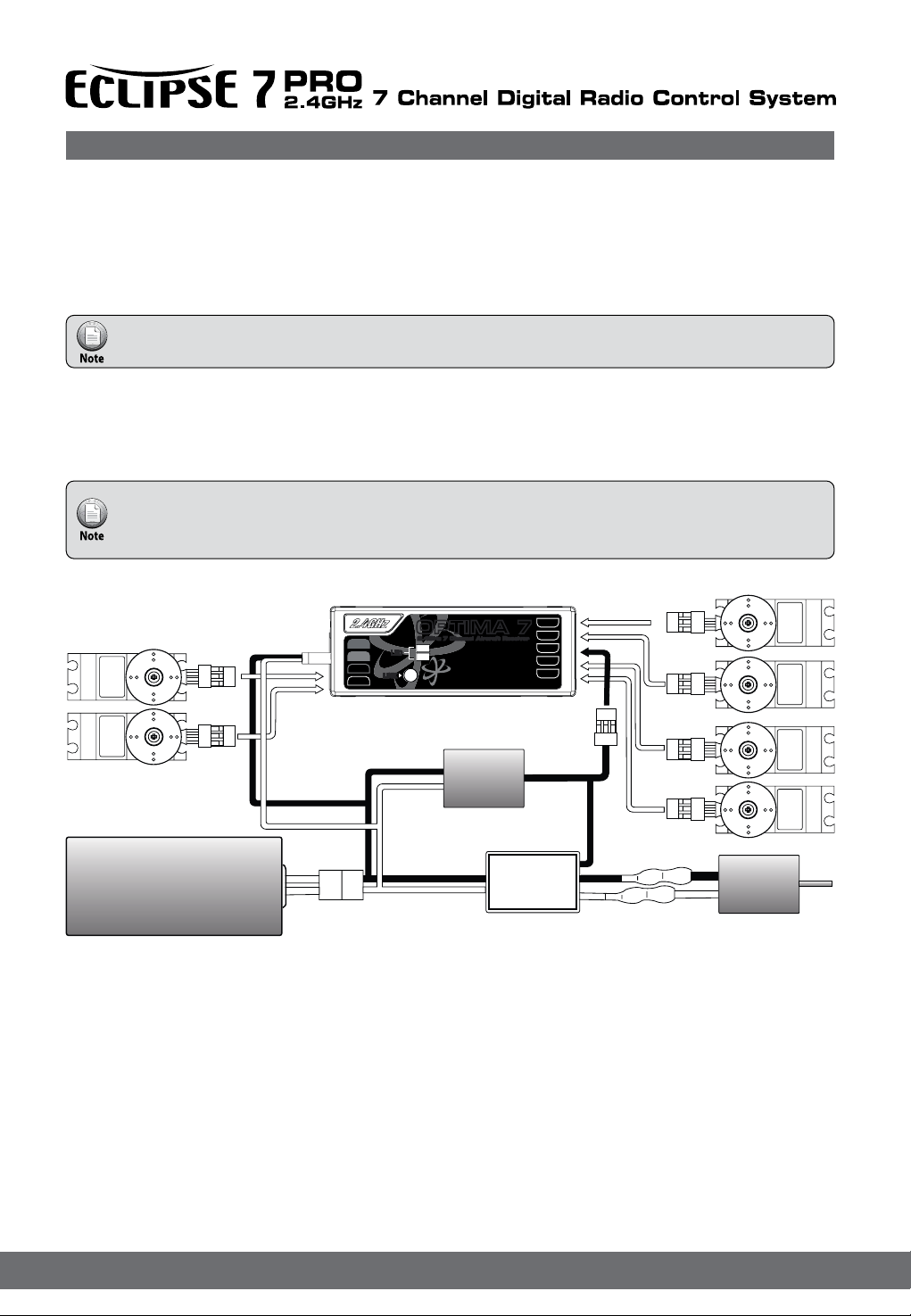
Optima Receiver Connection Diagrams
Glow, gas or electric powered aircraft using a separate receiver battery supply.
Follow this connection diagram when using a dedicated 4.8 to 6V. NiMH battery pack, or *2S Li-Po/Io/Fe batteries
Verify your servos are rated for use with these higher voltage batteries or use a regulator.
SERVO
ADAPTIVE
FREQUENCY HOPPING
SPREAD SPECTRUM
CH1
CH2
CH3
CH4
CH5
DATA
SPC
BAT/CH7
CH6
OPTIMA 7OPTIMA 7
2.4GHz 7 Channel Aircraft Receiver2.4GHz 7 Channel Aircraft Receiver
LED
LINK
LINK
LED
2.4GHz
Telemetric
AFHSS
SERVO
Receiver
Battery
Electric powered aircraft with Electronic Speed Control
Use this method on electric planes using ESC’s providing power to the receiver and servo functions
SERVOSERVO
DATA
SPC
BAT/CH7
CH6
OPTIMA 7OPTIMA 7
2.4GHz 7 Channel Aircraft Receiver2.4GHz 7 Channel Aircraft Receiver
LED
LINK
LINK
LED
2.4GHz
Telemetric
AFHSS
ADAPTIVE
FREQUENCY HOPPING
SPREAD SPECTRUM
CH1
CH2
CH3
CH4
CH5
SERVO SERVO
SERVOSERVO
Engine
SERVO SERVO
BEC
Power Battery
Optional BEC shown in diagram is used if the servo power requirements exceed that which the ESC provides.
ESC
5
SERVOSERVO
Motor
Page 8
Set-up Use of the Hitec 2.4GHz System
General Use Guidelines
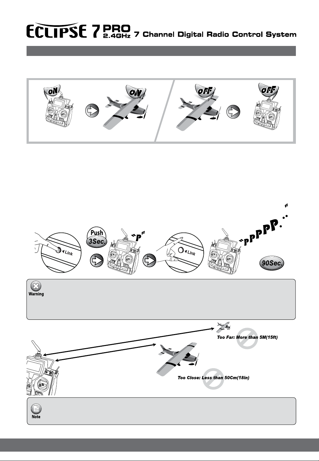
To turn the system on and off, use the following sequence at all times
Turning On -Turn on the transmitter, then turn on the receiver. Turning Off -Turn off the receiver, then turn off the transmitter.
Range Check Function
It is critical that before each ight session you perform a range check that conrms the signal between the receiver and transmitter is appropriate. Unlike the FM/PPM or PCM signal radios, 2.4GHz systems use a xed shorter, stubby transmitter antenna, so
called rubber duck antenna. So the traditional method of range check, lowering the transmitter antenna, is not applied.
The Hitec 2.4GHz System uses a power-down mode to reduce the transmitter signal strength.
Once the power-down mode is activated it runs for about 90 seconds, effectively shortening the range to 30 meters, or 100
feet. During this power-down mode that you should walk away from the secured aircraft carrying the transmitter to a minimum
distance of approx. 30 meters or 100 feet, testing the effective range.
How to use Power-Down
- Before each ying session, conrm the radio system is working properly.
- Before the engine or motor is started, turn on the system as explained above.
Then make sure all the servos and control surfaces are working properly.
If any control surface is not moving properly, do not y the aircraft until the problem is solved.
- If you are unable to accomplish a successful range check of 30 meters or 100 feet,
DO NOT ATTEMPT TO FLY.
Link Guidelines
- Link must be done within 15ft.(5m) of the transmitter and receiver.
- Transmitter and receiver need to be at least 18in.(50cm) from each other to link properly.
6
Page 9
Set-up Use of the Hitec 2.4GHz System
R
ID-Setup A.K.A, Link or Bind
Press and hold the Link button, and turn on the transmitter.
Release the link button.
Check if BLUE LED is blinking.
If RED LED is blinking, press
the link button for 2 sec., so
that LED changes to the BLUE.
Check if RED LED is blinking.
If BLUE LED is blinking,
press the link button for 2 sec.,
so that LED changes to the RED.
Press and hold the link button on Receiver and turn on the power.
l
e
n
r
n
e
a
v
i
h
e
C
c
e
6
R
z
t
H
f
a
G
r
4
.
c
2
ir
A
Both RED, BLUE LEDs will blink rapidly
to nd the transmitter signal.
Release the link button when
RED LED on receiver glows steady.
When the link is completed, BLUE LED
Transmitter will blink.
l
e
n
r
n
e
a
v
i
h
e
C
c
e
6
R
z
t
H
f
a
G
r
4
.
c
r
2
i
A
Release the link button.
When the link is completed, BLUE LED
Transmitter will blink while RED LED
Transmitter glows steady.
To save the setting, please reboot (Turn Off & On) both transmitter and
receiver.
When they are turned on again, RED LED Transmitter
and BLUE LED on the receiver will glow steady.
When they are turned on again, you can hear continuous
beep sound. Both RED LEDs transmitterand receiver will
glow steady in normal status.
l
e
n
r
n
e
a
iv
h
e
C
c
e
7
Page 10

Set-up Use of the Hitec 2.4GHz System
SmartScan Function
Turn on the transmitter.
Press and hold the LINK button on the ECLIPSE 7 PRO for about 6 sec.
Release the LINK button when you hear two continuous beeps.
The ECLIPSE 7 PRO will automatically scan the frequency to nd the cleanest and the most
stable frequency in any area. (The BLUE LED on the transmitter will blink during the scanning for 3sec.)
When the scan is completed, the BLUE LED on the transmitter stops blinking and glows steady.
Re-boot the transmitter (turn Off and On) and follow the link process with your receiver.
Push
6Sec.
After “Scanning,” you need to do the link process again for all your receivers as receivers need new
frequency hopping codes from the Spectra 2.4 module.
FAIL-SAFE and Hold Mode
If you use the FAIL-SAFE function, and set it up properly, should the receiver signal somehow be interrupted or interference
were to occur, the servos will move to your pre-set FAIL-SAFE point you previously stored in the receiver during the FAIL-SAFE
set-up process.
If FAIL-SAFE has not been activated, the signal is switched off after the HOLD period of 1 sec. This means that the servos
become “soft” and remain in their last commanded position under no load (this may equate to full-throttle!), until a valid signal is
picked up again.
In the interests of safety, we recommend that FAIL-SAFE should always be activated, and the FAIL-SAFE settings should be
selected so as to bring the model to a non-critical situation (e.g. motor idle / electric motor OFF, control surfaces neutral,
airbrakes extended, aero-tow release open, etc).
8
Page 11
Channel
Receiver
C
h
a
n
n
e
l
R
e
c
e
iv
e
r
C
hannel
R
eceiver
C
h
a
n
n
e
l
R
e
c
e
iv
e
r
Set-up Use of the Hitec 2.4GHz System
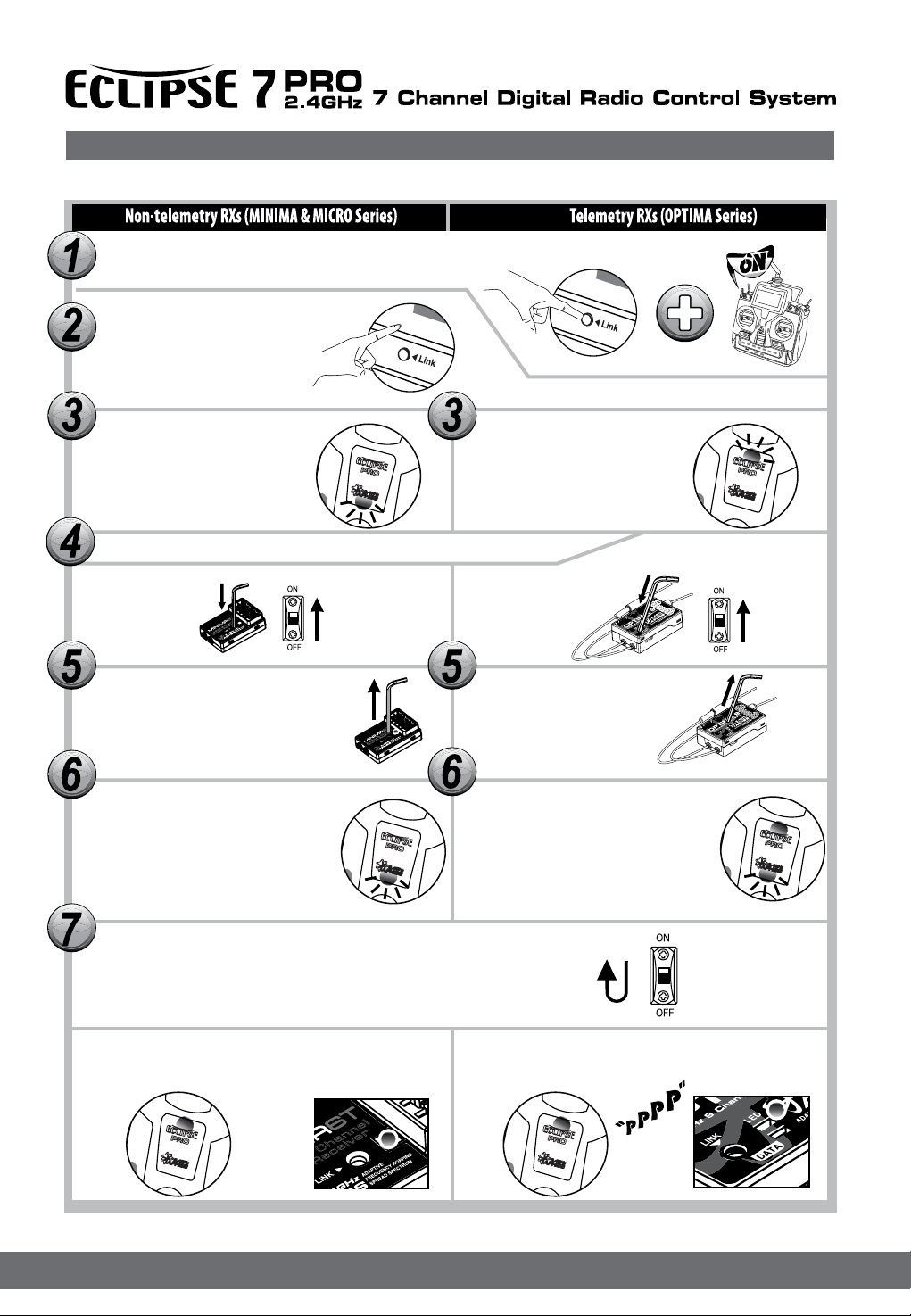
FAIL-SAFE Setup
Non-telemetry RXs (MINIMA & MICRO Series)
Switch on both.
Wait for the system to boot and control over the model.
l
e
n
r
n
e
a
v
i
h
e
C
c
e
6
R
z
t
H
f
a
G
r
4
.
c
r
2
i
A
Push the link button for 6 sec.
Push
l
e
n
r
n
e
a
v
i
h
e
C
c
e
6
R
z
t
H
f
a
G
r
4
.
c
r
2
i
A
6Sec.
Release the link button when LED is turned off.
You will see that both RED & BLUE LEDs will start blinking.
Wait
1Sec.
l
e
n
r
n
e
a
v
i
h
e
C
c
e
6
R
z
t
H
f
a
G
r
4
.
c
r
2
i
A
Telemetry RXs (OPTIMA Series)
Push
6Sec.
Release the link button when LED is turned off.
You will see that both RED & BLUE LEDs will start blinking.
Wait
2Sec.
Both RED & BLUE LEDs will blink alternately for 8sec.
During that time, move concerned transmitter sticks to
the desired FAIL-SAFE positions.
Fail-Safe position
Blinking
8Sec.
BLUE LED will glow steady once the setting
process is completed during above 8sec.
Both RED & BLUE LEDs will blink alternately for 5sec.
During that time, move concerned transmitter sticks to
the desired FAIL-SAFE positions.
Fail-Safe position
Blinking
5Sec.
RED LED will glow steady once the setting
process is completed during above 5sec.
Turn off both transmitter and receiver to save the Fail-Safe position. Now, Fail-Safe process is completed.
l
e
n
n
a
h
r
e
C
v
i
6
e
c
z
e
H
R
G
t
4
f
.
a
2
r
c
r
i
A
9
Page 12
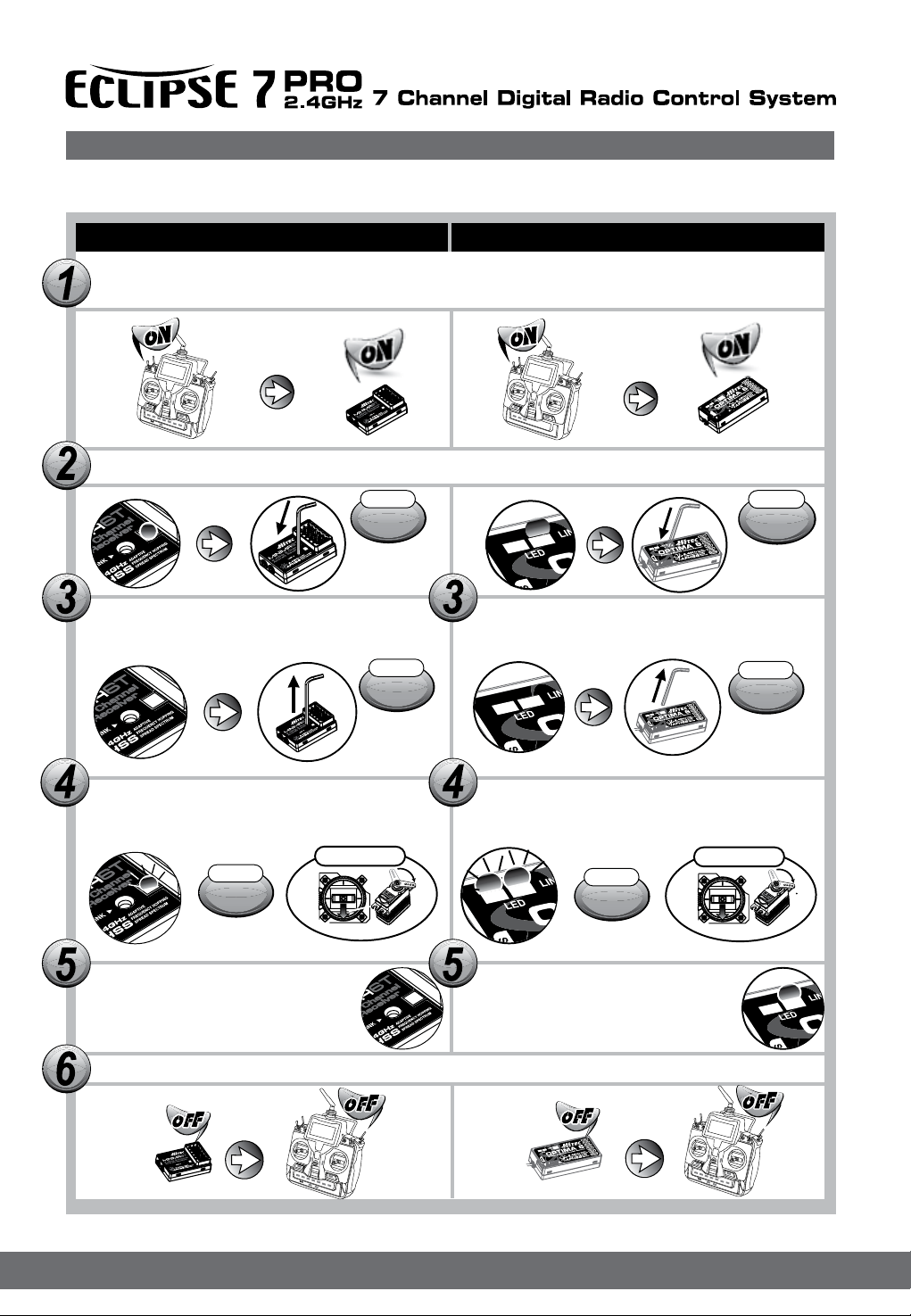
Set-up Use of the Hitec 2.4GHz System
FAIL-SAFE Setup
a. Switch on the transmitter, then the receiver, wait for the system to boot and you have control over the model.
b. Press and hold the receiver function button for 6 seconds, release the button. After 2 more seconds both red and blue
LEDs blink rapidly.
c. From the moment you release the button, the receiver will count 5 seconds during that time move all the transmitter
sticks and other controls to the desired FAIL-SAFE positions (e.g. motor idle, control surfaces neutral), and hold them
there.
d. After 5 seconds the system will save the FAIL-SAFE position. Relax all the control sticks.
e. Turn off the receiver, then the transmitter.
f. Turn on the system to use it. FAIL-SAFE is now activated.
Testing the FAIL-SAFE Setting
Move the sticks to positions other than the FAIL-SAFE settings, and then switch off the transmitter. The servos should now
move to the FAIL-SAFE positions previously stored, after the HOLD period (1 sec.) has elapsed.
How to turn FAIL-SAFE Off and reactivate the Hold Mode
a. Switch on the transmitter, then the receiver. Wait for the system to boot and you have control over the model.
b. Press and hold the receiver function button for 6 seconds and release it. After 2 seconds the red and blue LEDs will
blink rapidly.
c. Immediately press the button and release it.
d. FAIL-SAFE Mode is now deactivated and HOLD mode is activated.
e. Turn the transmitter off, then the receiver off.
f. Turn the system back on to use it..
If FAIL-SAFE is deactivated, the FAIL-SAFE position settings are also deleted!
The FAIL-SAFE settings should be checked every time before you run the engine/motor.)
Range Check Function
It is critical that before each ight session you perform a range check that conrms the signal between the receiver and transmitter is appropriate. Unlike the FM/PPM or PCM signal radios, 2.4GHz systems use a xed shorter, stubby transmitter antenna so
the traditional method of range checking your system by lowering the transmitter antenna will not work.
We instead use a power-down mode to reduce the transmitter signal strength. Once the power-down mode is activated it runs
for about 90 seconds, shortening the effective range 100 feet (30 m). During this power-down mode that you should walk away
from the secured aircraft carrying the transmitter to a distance of approx. 30 meters, testing the effective range
How to use Power-Down
a. Press the button on the module for 3 seconds, then both the blue and red LEDs will turn on with single beep sound.
Release the button. The 90-second countdown starts from the time the button released.
b. Walk away from the secured aircraft carrying the transmitter to a distance of approx. 100 feet (30 m), testing the ef
fective range.
c. To exit the power-down mode before the 90 seconds, press the button again to escape.
If you are unable to accomplish a successful range check of 90 feet, DO NOT ATTEMPT TO FLY.
Telemetry System
Currently there is a direct feedback telemetry function available in your Hitec 2.4 system. Plans are to have many more devices
available in the future.
Check the Hitec website at www.hitecrcd.com for more up-to-dated information.
The Hitec Eclipse 7 Pro and Optima Series receivers feature full telemetry capabilities (except Optima 6) and include a Low
Receiver Battery Warning as a basic function.
10
Page 13
Set-up Use of the Hitec 2.4GHz System
Low Battery Warning
The 2.4GHz system will automatically recognize the receiver battery voltage among 4 and 5 cell NiMH or NiCd batteries and
warns you, and also 2S LiPo/lo/Fe battery packs can be used with battery warning level customization.
- When battery level is high(4cell > 4.5V, 5cell > 5.6V): The red module LED glows constantly.
- When battery level is low(4cell < 4.5V, 5cell < 5.6V): Blue LED glows constantly and the red LED will blink fast. You will
hear a continuous loud beep from the module as a low receiver battery warning. Upon hearing the alarm, we advise
you to bring back the aircraft and land at once.
That you can adjust RX battery voltage warning level in B.WAR menu. Also via HPP-22 warning level can be adjusted.
SPC (Supplementary Power Connection) System
Hitecs exclusive optional receiver power system allows you to directly power the receiver from the main motor power battery of
an electric powered aircraft. Up to 35 Volts can be fed directly into the receiver to power JUST THE RECEIVER FUNCTION. It
will not power the servos. Almost all servos will burn-up if more than 6 Volts are used over a short period of time.
some Hitec servos are rated to be used at 7.4Volts. You will still need to supply power for your servos with a four or
ve cell NiMH receiver battery, 2 cell Li-Po and regulator set-up, or a commercially available BEC.
The SPC system was partially created to be integrated into future Hitec telemetry system devices.
Note Check the Hitec web site for more information on the availability of telemetry systems in the future.
SERVOSERVO
Power Battery
DATA
SPC
BAT/CH7
CH6
OPTIMA 7OPTIMA 7
2.4GHz 7 Channel Aircraft Receiver2.4GHz 7 Channel Aircraft Receiver
LED
LINK
LINK
LED
2.4GHz
Telemetric
AFHSS
BEC
ADAPTIVE
FREQUENCY HOPPING
SPREAD SPECTRUM
ESC
CH1
CH2
CH3
CH4
CH5
SERVO SERVO
SERVOSERVO
Motor
11
Page 14
Charge the Batteries!
Charging the Eclipse 7 Pro Ni-MH Batteries
Connect the transmitter charging cord into
the charging socket (on the rear of the case,
left side) and airborne Ni-MH batteries to the
receiver connector on the charger.
Connect the receiver battery to the
charging cord.
Plug the charger into a wall socket.
The charger’s LEDs should light,
indicating charging current is
owing. The batteries should be
left on charge for about 15 hours.
TRAINER
Try to charge the batteries with the
charger supplied
with your system exclusively.
The use of a fast-charger may
damage the batteries by overheating
anddramatically reduce their lifetime.
If you need to remove or replace the transmitter battery,do
not pull on its wires to remove it. Instead, gently pull on the
connector’s plastic housing where it plugs in to the transmitter.
The battery must be removed to charge it properly with a
“peak” charger.
PUSH
Operating With A Trainer Cord
An optional training cord is available from your dealer.
The cord may be used to help a beginning pilot learn to
f ly easily by allowing a second transmitter, operated by
an experienced instructor, to be connected to this system.
The instructor may override the beginning pilot at any
time to bring the model back under safe control. For
training
To use the trainer cord:
Set up both the student’s and instructor’s transmitters
to have identical trim and control motions.
Plug it into each transmitter, with power
switched off. The trainer jack is
on the back of the transmitter.
Turn the connector until its notches
line up and it ts without having
to be forced.
Turn on the instructor’s transmitter.
DO NOT turn on the student
PUSH
transmitter power.
Move the controls on the instructor’s transmitter, and verify
each control moves the proper direction.
Now verify that the student’s trims and control travels match
the instructor’s by using the trainer switch (the momentary
Trainer switch on the top left of the transmitter case) and
switching back and forth while leaving the control sticks and
trims alone, then moving the control sticks.
TRAINER
The instructor’s transmitter has normal control over
the model unless the trainer switch is pulled, passing
control to the student’s transmitter. If the student loses
control, the instructor can quickly “take over” by releasing
the trainer switch and controlling the model.
Other Adjustments
Adjustable length control sticks
You may change the length of
the control sticks to make your
transmitter more comfortable to
hold and operate.
A B
To lengthen or shorten your transmitter sticks, rst
unlock the stick tip by holding locking piece B and turning
stick tip A counterclockwise. Next, move the locking
piece B up or down (to lengthen or shorten).
When the length feels comfortable, lock the position by
turning locking piece B counterclockwise.
Stick lever tension adjustment
You may adjust the stick tension of your sticks to provide
the “feel” that you like for ying. To adjust your springs,
you’ll have to remove the rear case of the transmitter.
Using a screwdriver, remove the six screws that hold the
transmitter rear cover into position, and put them in a
safe place. Place some padding under the front of the
transmitter and place it face-down on the pad. Gently
ease off the transmitter rear cover and move it to the
right side of the transmitter, carefully turning it as you
would turn the page of a book. Now you’ll see the
view shown. Using a small cross-point screwdriver,
rotate the adjusting screw for each stick for the desired
spring tension. The tension increases when the adjusting
screw is turned clockwise, and
decreases for counterclockwise
motion. When you are satised
with the spring tensions, you
may close the transmitter.
Very carefully reinstall the rear
cover. When the cover is
properly in place, tighten the six
screws.
Tension Adjust Screw
Ratchet change
Some pilots, especially those ying helicopters, prefer a
“softer” or “smoother” ratchet action on the throttle stick.
An alternate ratchet that provides a smoother ratcheting
action is included as an accessory with your Eclipse 7 Pro
system. To change the throttle ratchet, remove the back
of the transmitter case as directed above in the “stick lever
tension adjustment” section. Then, unscrew the ratchet
retaining screw, remove the old ratchet, and replace
with the new one. Tighten the retaining screw gently but
rmly. Then, replace the transmitter rear cover.
12
Page 15
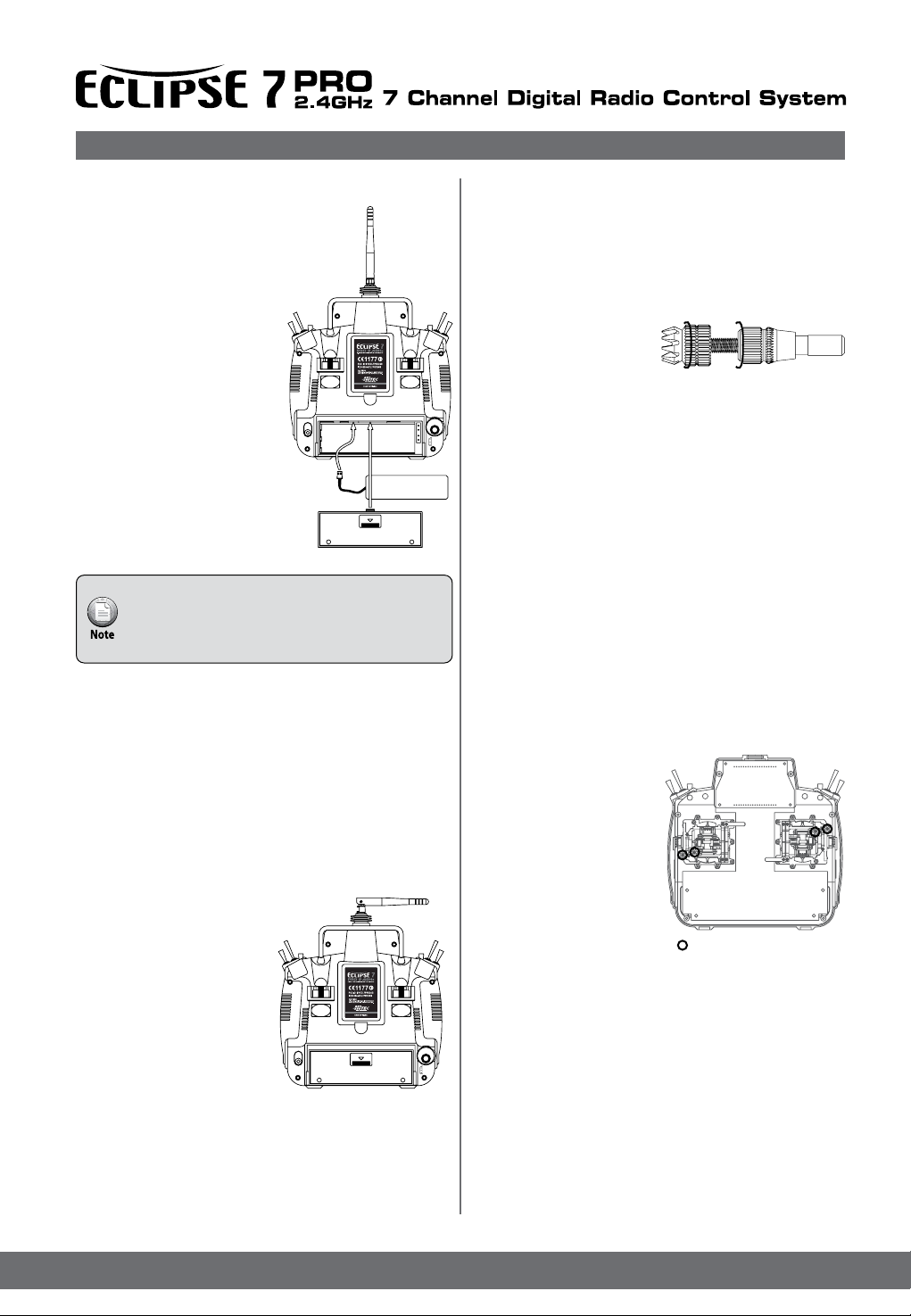
Factory Service Repair Information
Changing the Eclipse 7 Pro transmitter’s mode
If you wish to change current system’s Mode from the factory
installed (Mode 2 1, 3 or 4)
Please remove the Transmitter Battery rst, after that remove
all backside screws carefully, and then lift back case gently.
In order to change mode , please adjust Tension Screws and
Mode Screws according to below gures.“
Mode
Change
Screw
Mode
Change
Screw
MODE 1 MODE 2
ELEV THRO
RUDD RUDD
ELEV THRO
AILE AILE
THRO ELEV
AILE AILE
MODE 3 MODE 4
THRO ELEV
RUDD RUDD
Hitec-RCD, Inc.
12115 Paine St.
Poway, CA 92064
TEL: 1-858-748-6948
FAX: 1-858-748-1767
Web site: http://www.hitecrcd.com
Factory Service Repair Information
(for U.S.& Canada only)
Please read the warranty card supplied with your system,
and return it so your system will be under warranty.
Before you decide to have your system repaired, if there
is no apparent physical damage, read this instruction
manual again and check to be sure that you are operating
the system as it is supposed to be operated. If you
are still having trouble, pack up your system in its original
shipping materials and send it to the factory or the nearest
authorized Hitec R/C Service Center.
Be sure to include a note in your package that describes
the trouble in as much detail as possible, including:
Symptoms of the problem in as much detail as you can
provide, including any unusual mounting conditions
or equipment orientation
A list of items you are sending, and what you want to
be repaired.
Your name, address, and telephone number
If you have any questions regarding this product, please
consult with Hitec’s service center. The address and
telephone numbers of our service center is given below.
Telephone inquiries are accepted from 8:00 AM to
4:30 PM weekdays (closed on holidays).
13
Page 16
Eclipse 7 Pro “Mode2” Control and Switch Assignments
ECLIPSE 7 PRO MODE 2 TYPE
SWITCH CONFIGURATION LIST FRONT
Flight Mode Switch
ACRD Elevator to Flap Mix
Condition Mix 1 Trim, D/R, EXP
Nomal Trim, D/R, EXP
Condition Mix 2 Trim, D/R, EXP
Landing Mix
Glider Condition Mix 1
4-Wing Speed Flap Trim Offset 1
Elevator to Flap Mix
Normal Trim, D/R, EXP
Condition Mix 2
4-Wing Speed Flap Trim Offset 2
HELI Rudder to Throttle Mix
Nomal Trim, D/R, EXP, Gyro Gain
ldle UP 1 Trim, D/R, EXP, Throttle Curve
ldle UP 2 Trim, D/R, EXP, Pitch Curve
Elev. D/R
ACRD Elevator D/R
Elevator D/R
Motor ON/OFF CH3
Elevator D/R
Rudder D/R
ACRD
P-Mix 4 ON/OFF
Aileron to Rudder Mix On/OFF
Rudder D/R
Glider P-Mix 4 ON/OFF
Aileron to Rudder Mix
Rudder D/R
HELI P-Mix 2 ON/OFF
Rudder D/R
ACRD/HELI Throttle Trim
Glider Flap Trim
Flight Condition Switch
ACRD P-Mix 5 ON/OFF
Condition 3 Trim, D/R, Exp (Ail, Elev, rudd)
Glider P-Mix 5 ON/OFF
Condition 3 Trim, D/R, Exp (Ail, Elev, rudd)
4-wing Aileron to Flap Coupling Mix
HELI Throttle Hold
Condition 3 Trim, D/R, Exp (Ail, Elev, rudd)
Gyro Gain
Hold Pitch Curvo
Gear
ACRD Landing Gear ON/OFF
P-Mix3 ON/OFF
Glider P-Mix3 ON/OFF
Crow Mix ON/OFF
HELI P-Mix 1
Elev. D/R
ACRD/Glider/HELI Aileron D/R
CH7 Switch
ACRD P-MIX 1 ON/OFF
P-MIX 2 ON/OFF
Glider P-MIX 1 ON/OFF
P-MIX 2 ON/OFF
Flap to Aileron Mix
Flap to Elevator Mix
HELI CH 7 Control
(Heading lock ON/OFF)
Elevator Trim
Rudder trim
Select to Voltage
Trim Data
Model Name
Acro/HELI Engine Low Position Hold
Glider X
Acro/HELI Engine Cut off
Glider X
This gure shows the assignments for a Mode 2 system as supplied by the factory in North America.
Note that some of the functions will not operate until activated in the mixing menus.
14
Aileron Trim
Integral Timer Data Reset
Page 17
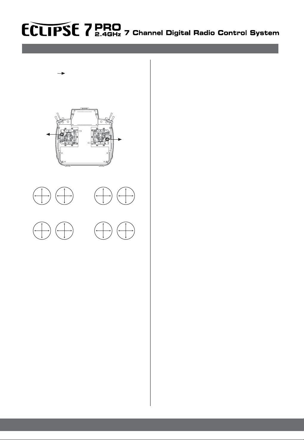
Eclipse 7 Pro “Mode2” Control and Switch Assignments
ECLIPSE 7 PRO MODE 2 TYPE
SWITCH CONFIGURATION LIST REAR
VR2
ACRD CH7 Control
Glider 2-Wing Ch7 Control
4-Wing 2nd-Flap Aileron Trim
HELI Hovering Pitch
PUSH
VR1
ACRD Flap Trim Control
Glider Flap Control
Flap to Aileron Mix Control
Flap to Elevator Mix Control
HELI Hovering Throttle Control
TRAINER
15
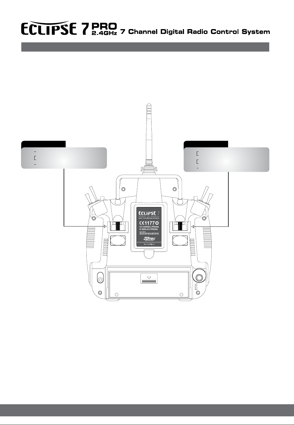
Page 18

Transmitter Input Buttons
The buttons are used for different things as follows:
1.The Edit/Display Up & Down buttons (1)allow
you to move up and down within the model
menus, and move within the regular display.
select options within a particular function,
and control the timer function.
2.The Data +Increase & -Decrease buttons (3)allow you to increase or decrease the numerical settings for a function.
3.The Clear Active/Inhibit button (4)resets numbers, and turns functions on and off.
4.The Engine Lock button (5)holds the throttle channel while other channels may respond to the transmitter.
5.The Engine Cut button (6)closes the throttle so that you can kill the engine without touching the trim lever.
You'll learn how to use these buttons in the setup sections that follow
6.The link button Can be used for that link process between ECLIPSE 7 PRO to a Optima or Minima series receivers, entering
the power down mode for range checks, and the Normal/Scan Mode set-up
Receiver - Servo Connection List
The table below shows the hookups that should be used for each of the model types. Note that some functions shown will not
operate until they are activated in the transmitter.
Receiver channel Aircraft (ACRO) Glider (GLID) Helicopter (HELI)
aileron or right aileron
1
2
3
4
5
6
7
The servo response varies with the selected function. Standard options are shown rst.
or right aperon (FLPN)
or right elevon (ELVN)
Elevator or V-tail right side
(VTAL) or left elevon (ELVN)
or left Elevator(AILV)
throttle
rudder or V-tail left side
(VTAL)
landing gear left aileron gyro sensitivity
ap (controlled by VR1) or
left aperon (FLPN) or left
aileron
optional, controlled by VR2
or right Elevator(AILV)
right aileron(or rudder for
rudder-elevator models)
elevator or V-tail right side
(VTAL)
spoiler, throttle (on-off
controlled by Gear switch)
rudder or V-tail left side
(VTAL)
right ap (4WNG) or single
ap
(2WNG)
left ap (4WNG) or proportional
channel, controlled by VR2
(2WNG)
roll
or swash servo 1 (120’)
or swash servo 1 (140’)
or swash servo 1 (180’)
Elevator
or swash servo 2 (120’)
or swash servo 2 (140’)
or swash servo 2 (180’)
throttle
yaw
pitch
or swash servo 3 (120’)
or swash servo 2 (140’)
or swash servo 2 (180’)
optional, controlled by Gear
switch
16
Page 19
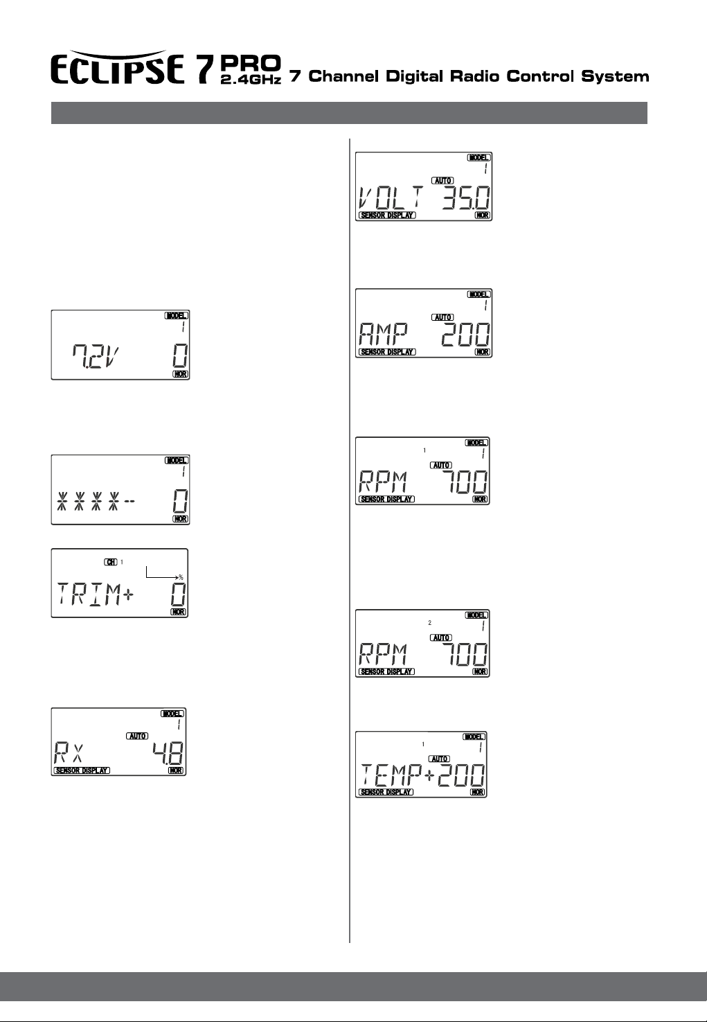
Telemetry system Information
When you rst turn on your transmitter, the rst screen
shown below appears on the LCD display. Before ying,
or even starting the engine, BE SURE that the model
number appearing in the higher right of the display
matches the model that you are about to y!
If you don’t, reversed servos and incorrect trims will lead
to an immediate crash.
You can scroll up and down through the startup screen
by pressing one of the two Edit keys (the two keys on the
far left). If you press timer or engine cut or lock keys, you
go directly to those functions regardless of the display.
This screen appears at
startup. The model
memory number is shown
by state in gures.
Battery voltage is shown in
time is on the lower right. You can reset the operating time
display by hitting the Clear button (the one on the farthest
right).
Do this after each charge to keep track of your operating time
on a single charge.
Flashing
is, you have to move it! Be sure to move it back to where it
was. Note that the CH3 trim only moves downward, so if you
need more engine RPM, set up idle with the trim at -25% so
you can increase it if needed.
by in lower right of the display. Display can be shown 0v to 35v
You can check all Telemetry information by select to Auto or
Normal. If you select Auto ,by pressing Cursor right ,display
will showing all Telemetry information in every 2sec rotationally
. If you select Normal , you have to select what you want to
see the Telemetry information by pressing the Cursor .
the bottom left, and operating
Pressing the Down button
gives the Model Name display
you can check the current
Model name by this screen
Pressing the Down button
gives the Trim display
(different numbers may
appear depending on the
model type). To see where
the trim for a certain channel
Pressing the Down button
gives the Telemetry information
display when you use Optima
series receivers(Hitec Telemetry
capable receivers)
you can check receiver voltage
VOLT
BLUE with HTS-VOLT which
attached receiver or Electric
powered aircraft’s main battery.
Voltage value appears in lower
right in the display as you see
left diagram . voltage range
is 0v to 99.9v. ( If you not use HTS-SS, Numeral 0 will appear
in lower right of the display )
AMP
You can check Current of your
battery using HTS-SS BLUE
with HTS-C50/C200 which
attached receiver or Electric
powered aircraft’s main battery.
Current value appears in lower
right in the display . As you see left diagram. Current range
is 0 to 200.( If you not use HTS-SS, Numeral 0 will appear in
lower right of the display )
RPM
You can check the RPM of your
aircraft using HTS-SS BLUE
with HTS-RPM .
Hitec have two types of RPM
sensors, one is O-RPM(Optical
RPM Sensor ,Optimized Heli),
the other is M-RPM(Magnetic RPM Sensor, all aircraft using
props). RPM value appears in lower right in the display .As
you see above diagram, you can see the small numeral 1, this
information coming from HTS-SS BLUE RPM Sensor rst slot.
Real RPM value can be calculated by X100 displaied value.
Ex) if you see 700 in the display, actual RPM is 70,000 .
As you see to left diagram, this
information coming from HTS-
SS BLUE RPM sensor second
slot.
You can see small numeral 2 in
the display
This is showing second RPM sensor information.
TEMPERATURE
You can check the temperature
of your aircraft’s engine , mufer
, ESC , batteries and etc. that
using HTS-SS BLUE, HTS-SS
with HTS-TEMP(You can use
maximum 4 temperature sensors).
Temperature value appears in lower right in the display .As
you see left diagram, you can see the small numeral 1, this
information coming from HTS-SS BLUE, HTS-SS Temperature
sensor rst slot. Temperature range is -40 to 200 .
17
Page 20
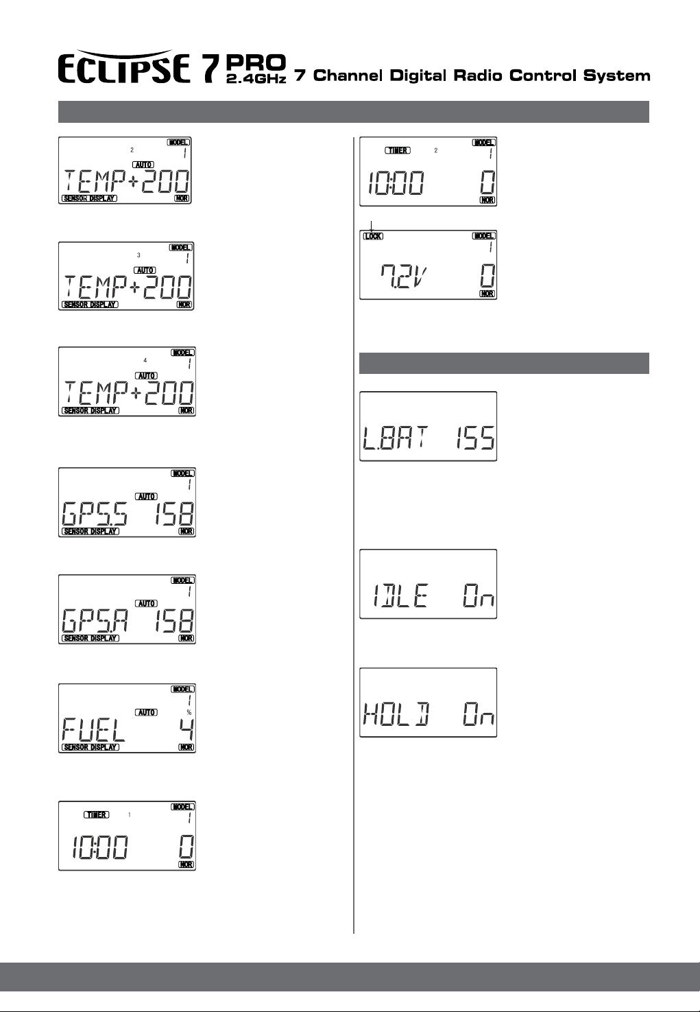
Telemetry system Information
As you see to left diagram, this
information coming from HTSSS BLUE ,HTS-SS temperature
sensor second slot.
You can see small numeral 2 in
the display This is showing
second TEMP sensor information.
As you see to left diagram, this
information coming from HTSSS BLUE ,HTS-SS temperature
sensor third slot.
You can see small numeral 3 in
the display This is showing third
TEMP sensor information.
As you see to left diagram, this
information coming from HTSSS BLUE ,HTS-SS temperature
sensor fourth slot.
You can see small numeral 4 in
the display
This is showing fourth TEMP sensor information.
GPS SPEED
You can check the Speed of
your aircraft using HTS-SS
BLUE, HTS-SS with HTS-GPS
. GPS Speed value appears in
lower right in the display . GPS
Speed range is 0 to 999 Km/h.
GPS ALTITUDE
You can check the Altitude of
your aircraft using HTS-SS
BLUE, HTS-SS with HTS-GPS.
GPS Altitude value appears in
lower right in the display. GPS
Altitude range is 0 to 999m
left diagram shows second
TIMER of the DUAL TIMER
LOCK indicator
Pressing the Lock buttonlocks
the throttle servo and holds it
where you last commanded it.
This may be used as a safety
feature when you are carrying
the model and transmitter to
ensure you don’t accidentally give throttle. It is shown by the
LOCK indicator
Warning Displays
The LOW BATTERY warning is
displayed when the transmitter
battery voltage drops below 6.6
volts, and a beeper sounds.
The operating time is still shown
on the right. If you reset this
each time you charge the system, you will have a good idea of
how long you can safely operate.
WHEN THE BEEPER SOUNDS, LAND YOUR MODEL AS
SOON AS POSSIBLE BEFORE LOSS OF CONTROL DUE
TO A DEAD TRANSMITTER BATTERY
The IDLE ON warning is
displayed when the transmitter
is powered up with the Idle-up
switch on in the helicopter mode
only.
You can turn this off by moving
the Flt. Mode switch back. For your safety, the transmitter will
not broadcast until this alarm is ended.
FUEL
you can check the fuel amount
of your model using HTS-SS
with HTS-FUEL, fuel level can
be checked by appears numeral
0 to 4.(this function only can use
HTS-SS. HTS-SS BLUE cannot
provide this function)
DUAL TIMER
Pressing the two Timer button at
the same time that
gives the Timer display .you can
start the timer pressing Start
button . Stop and Reset also
same function as like key name.
You can nd out rst TIMER of the DUAL TIMER that seeing
small numeral 1 in the display . you may move to second
TIMER pressing UP or Down button.
The HOLD ON warning is
displayed when the transmitter
is powered up with
the Throttle hold switch on
in the helicopter mode only
when throttle hold values are
programed. You can turn this off by moving the Flt. Cond.
Switch back. For your safety, the transmitter will not broadcast
until this alarm is ended.
18
Page 21

Model Setup Functions
This section describes the model setup functions that are used to choose all of the operating features of a particular model
memory. These functions are used to select the model memory, the model type (from airplanes, gliders, and helicopters), set
the Timer, and other useful functions. These functions are used to set up a new model or a new model memory, to switch
between memories, and to change transmit shift.
Map of Basic Menu Functions
M.SEL Model select
VER- 1.010
RESET Reset Memory
TIME Timer1, 2 setup
COPY Data Copy
ACRO Acrobatic model mode
HELI Helicopter model mode
GLID Glider model mode
2WING Two Servo Wing (GLID only)
4WING Four Servo Wing (GLID only)
NOR Normal swashplate (HELI only)
120` 120` swashplate (HELI only)
140` 140` swashplate (HELI only)
180` 180` swashplate (HELI only)
**** Model Name (four Letters +
Up to three numbers)
MODE Mode 1, 2, 3, 4 changeable
IMP Unit Select
RPM RPM Check
AMP AMP Check
B,WAR Rx Battery Warning
Model select ( M.SEL )
Version ( VER- 1.010 )
Reset Memory ( RESET )
Timer1, 2 setup ( TIME )
Data Copy ( COPY )
Acro, Heli, Glide Model Select ( Heli )
SWASH /120 /140 /180 /NOR Select ( NOR)
Model Name Select ( ACRO 001 )
Mode 1, 2, 3, 4 changeable ( MODE )
Unit Select ( IMP )
RPM Check ( RPM )
AMP Check ( AMP)
Rx Battery Warning ( B,WAR )
PowerOnWhilePressing
bothEdit/Displaykeys
Model Setup Functions
MODL – Model Select
. Your Eclipse 7 PRO system can store up to sixteen independent sets of model data in its memory. The Model Select
(MODL) function allows you to choose from any of the
seven sets of model data.
You can assign a four-character name to each model memory.
The model names are not visible when you wish to switch
memories. There are several ways to keep track of which
model is in each memory. You may attach a small piece of
white tape to the transmitter and write the model’s name along
with the model setup number (and its channel number), or you
may use a notebook, or label the model with its memory number prominently near its on-off switch inside the fuselage.
Choosing a model memory to load
Flashing
you into the model select (M.SEL) menu.
3. Select the desired model number by pressing the Cursor
Right or Left button. At this time, the selected model number
will blink on and off.
4. Switch power off.
5. Switch power back on. The previously-selected model
number is indicated by the arrow above the model numbers
in the display.
1. Start with the transmitter
switched off.
2. Turn on your transmitter
while pressing both of the
two Edit keys (the two keys
on the far left). This gets
VERSION
Left diagram shows current software version of Eclipse 7 Pro.
The software can be upgraded
by using HPP-22 device.
RESET –Data Reset
The Reset function is used to clear out an existing set of
model data within a single model memory, the current one.
This function resets all data to the factory default values, and
may be used to get a “fresh start” so that you may begin with
a clear memory before you input new model settings into a
memory that had been used for another model.
Flashing
The model select (M.SEL) menu will be displayed.
2. Press the Up or Down arrow key until you get into the Reset
(REST) menu.
This display has the word “REST” ashing on and off.
(If you’re already in the setup menus, you can just press the
Up or Down arrow key to get here.)
3. IF YOU ARE SURE YOU WANT TO RESET and clear
out the current model memory, press both the +Increase
and -Decrease Data keys at the same time. The transmitter
Resetting the memory
1. With the transmitter switched
off, turn on your transmitter
while pressing both of the two
Edit keys(the two keys on the
far left).
19
Page 22

Charge the Batteries!Model Setup Functions
will beep twice to indicate a successful reset.
4. Press the Up or Down arrow keys to get to another
setup menu, or switch power off.
5. Switch power back on. You may now set up the details
of your model in the Edit mode.
CAUTION: WHEN YOU COMMAND RESET, YOU’LL ERASETHE MEMORY YOU’RE IN AND LOSE ANY PROGRAMMINGYOU HAVE ENTERED. DON’T DO THIS UNLESS YOU
ARE
POSITIVE YOU WANT TO FLUSH OUT THAT MEMORY
ANDSTART FROM SCRATCH WITH THE FACTORY DEFAULTSETTINGS.
TIME – Timer Function Setup
1. With the transmitter switched
off, turn on your transmitter
Flashing
while pressing both of the two
Edit keys(the two keys
on the far left).
The model select (M.SEL) menu
will be displayed
Flashing
2. Press the Up or Down
arrow key until you get into
the Reset (TIME) menu. The
word “TIME” will ashing on and
off. (If you’re already in the set-up menus, you can just press
the Up or Down arrow key to get here.)
3. To change the number of minutes shown, press the
+Increase and -Decrease Data keys until you see the
amount you desire. You may select from 0 to 60 minutes.
4.Pressing the cursor will bring you to get second timer .
5. Press the Up or Down arrow keys to get to another
setup menu, or switch power off.
6. Switch power back on. You may now set up the
details of your model in the Edit mode.
COPY-Copy Model
The COPY function is used to copy the model data stored
in the current model memory into another model memory.
This function is handy to use to start a new model that’s
Copying from one model memory to another
2. Press the Up arrow key.
This gets you into the model
copy (COPY) menu. (If
you’re already in the setup
menus, you can just press
the UP or Down arrow key to get here.)
3. The source model memory (the memory that will be
similar to one you have already
programmed, and is also
handy for copying the current
model data into another
model memory as a backup.
1. With the transmitter switched
off, turn on your transmitter
while pressing both of the two
Edit keys (the two keys
on the far left). The model select
(M.SEL) menu will be displayed.
duplicated) is the current one, indicated by the numeral (located higher right)
. To select your destination model number,
press the Left or Right Cursor keys. The selected destination
memory number is shown by the ashing numeral .
4. Press the +Increase and -Decrease Data keys at the
same time. The transmitter beeps twice rapidly, indicating
the copy has been completed. THIS WILL ERASE ALL
THE OLD SETTINGS IN THE SLAVE MODEL MEMORY,
SO BE SURE YOU’RE IN THE CORRECT MODEL
BEFORE YOU COPY MODEL!
5. Switch power off.
6. Switch power back on. If you wish to go to the newly saved
memory, repeat step 1.
ACRO, HELI, GLID - Model Type Select
This function is used to select the type of model to be
programmed in the current model memory. You may
select from aircraft (ACRO), gliders (GLID), and helicopters
(HELI). If you select glider or helicopter types, you
will need to set the wing type (for a glider) or the swash
type (for a helicopter). These settings are covered below.
Flashing
Flashing
Flashing
type or swash type in the GLID and HELI model settings, see
the sections below.]
4. If you wish to change the model type from that displayed,
press on the Left or Right Cursor buttons until the model type
you want, either ACRO,GLID, or HELI, appears.
5. To select your desired model type, press both the
+Increase and -Decrease Data keys simultaneously.
Two beeps tell you that the new model type is now registered.
THIS WILL ERASE ALL THE OLD SETTINGS IN THE
MODEL MEMORY, SO BE SURE YOU’RE IN THE CORRECT
MODEL MEMORY BEFORE YOU CHANGE MODEL TYPE!
6. Press the Up or Down arrow keys to get to another
setup menu, or switch power off.
7. Switch power back on. You may now set up the details
of your model in the Edit mode.
Selecting the Model Type
1. With the transmitter switched
off, turn on your transmitter
while pressing both of the two
Edit keys (the two keys
on the far left). The model select
(M.SEL) menu will be
displayed.
2. Press the Down arrow key.
This gets you into the type
select menu. The current
model type will be ashing on
and off. (If you’re already
in the setup menus, you can just
press the Up or Down arrow key
to get here.)
3. If the model type you want is
displayed, you’re done.
[If you wish to change the wing
20
Page 23

Model Setup Functions
Wing & Swashplate Type Selection
If you are using the glider (GLID) or helicopter (HELI)
setting menus, you must tell the Eclipse 7Pro system what
type of model you are using. In the case of a glider, you have
to specify whether it has two (2WNG) or four (4WNG)
wing servos (most slope gliders use two wing servos, and
competition gliders use four wing servos, two each for
outboard and inboard ailerons and aps). Helicopters may
have one servo each for blade angle, roll and pitch(NOR)
or they may use three servos in concert on the swash to
provide these functions (120’, 140`,180’). Note that these
menus will not be available unless you have selected the
GLID or HELI model types.
Selecting the Wing or Swashplate Type
setup menu, and WING will be highlighted: If you’re in HELI
mode, SWASH will be highlighted and you can select from
three swashplate types: NOR, 120’,140` and 180’
If you’re happy with the wing or swash type that is
displayed, go on to the next step. If you wish to change
the wing or swashplate type from that displayed, press on
the Left or Right Cursor buttons until the wing/swash
type you want appears. CAUTION: if you change types,
you may lose settings in the menus.
4. Press the Up or Down arrow keys to get to another
setup menu, or switch power off.
5. Switch power back on. You may now set up the
details of your model in the Edit mode.
1. Select the GLID or HELI
model type in the Model Type
Select menus (see above).
2. With the transmitter
switched off, turn on your
transmitter while pressing
both of the two Edit keys
(the two keys on the far left).
The model select (M.SEL)
menu will be displayed.
3. Press the Up or Down
arrow keys: In the GLID
mode, you’ll enter the wing
21
Page 24

Model Setup Functions
Model Name
The Model Name function is used to create an alphanumeric
name which is stored in the model memory along with the rest
of the model settings. You will nd it useful to help keep track
of multiple models. The model name can be four alphabetic
characters, along with up to three numbers following.
The letters may be used to abbreviate the model’s name, and
the numbers may be used for the memory number, or you
may wish to store that model’s channel number so you can
remember easier.
Flashing
left). The model select (M.SEL) menu will be displayed,
with “stars” to represent letters to be chosen.
2. Press the Up or Down arrow key until you get into the model
name menu. You’ll see the display as shown to the right.
The rst character of the name will be ashing on
and off. (If you’re already in the setup menus, you can
just press the Up or Down arrow key to get here.)
3. To change the rst character, press the +Increase and
-Decrease Data keys until you see the character you desire.
You may select from the upper case letters A ~ Z, ,
+, -, /, and the numbers 0 ~ 9.
4. Press the Right Cursor key to move to the next character.
5. Press the +Increase and -Decrease Data keys until
you see the character you desire.
6. Repeat the previous two steps to input the third and
fourth characters of the display.
7. Press the Right Cursor key to move to the number
displays on the right.
8. Press the +Increase
10. Switch power back on. You may now set up the details of
your model in the Edit mode.
Mode – Mode Select
will be displayed . You can change the Mode 2 to Mode 1,
Mode 2 to Mode 3 or 4.
but If you want to change mechanically , please send this
Eclipse 7 Pro to service center. This
change procedure only can change the software of Eclipse 7
Pro.
Inputting a Model Name
1. With the transmitter
switched off, turn on your
transmitter while pressing
both of the two Edit keys
(the two keys on the far
and -Decrease Data keys
until you get to a number
that you like. This can be
any number from 0 to 199.
9. Press the Up or Down arrow
keys to get to another setup
menu, or switch power off.
1. With the transmitter switched
off, turn on your transmitter
while pressing both of the two
Edit keys
(the two keys on the far left).
The Mode select (MODE) menu
2.Press the Up or Down arrow
keys to get to another setup
menu, or switch power off.
3. Switch power back on. You
may now set up the details of
your model in the Edit mode.
MET(Metric), IMP(Imperial) – Unit Select
1. With the transmitter switched
off, turn on your
Flashing
transmitter while pressing both
of the two Edit keys
(the two keys on the far left).
The Imperial select (IMP) menu
will be displayed .
2. Press the Right or Left Cursor
key to select MET or IMP .
Flashing
* Metric = °C m Km
* Imperial = °F ft mile
3. Press the Up or Down arrow
keys to get to another setup
menu, or switch power off.
4. Switch power back on. You may now set up the
details of your model in the Edit mode.
RPM - RPM Check
Flashing
will be displayed . you can check aircraft RPM using RPM sensor (You can use maximum 2 RPM sensors).
Flashing
3. Press the Right Cursor key to select RPM1 or RPM2 .
4. Press the Up or Down arrow keys to get to another
setup menu, or switch power off.
5. Switch power back on. You may now set up the
details of your model in the Edit mode
1. With the transmitter switched
off, turn on your
transmitter while pressing both
of the two Edit keys
(the two keys on the far left).
The RPM select (RPM) menu
2. To change the
propeller(prop), press the +In-
crease and
-Decrease Data keys until you
see the type of prop you desire.
There are 3 kinds of props- 2-b
(blades) ,3-b , 4-b.
AMP- Amperage Check
1. With the transmitter switched off, turn on your transmitter
while pressing both of the two Edit keys (the two keys on the
far left). The Amperage select (AMP) menu will be displayed
Flashing
2. Press the Right Cursor key to
select 50 or 200
This numerals means AMP. 50
is 50AMP.
3. Press the Up or Down arrow
keys to get to another setup
menu, or switch power off.
22
Page 25

Model Setup Functions
Flashing
4. Switch power back on. You
may now set up the details of
your model in the Edit mode.
B,WAR - Rx Battery Warning
Flashing
menu will be displayed . this is very useful for knowing the battery recharging timing.
2.To change the Battery warning point, press the +Increase
and
-Decrease Data keys until you see the voltage value you
desire.
Set up range is from 4v to 35v.
1. With the transmitter switched
off, turn on your
transmitter while pressing both
of the two Edit keys
(the two keys on the far left).
The B.WAR select (B.WAR)
23
Page 26

AIRCRAFT (ACRO) MENU FUNCTIONS
This section describes the menu functions for xed-wing aircraft, provides a detailed setup example, and then describes the
functions individually. Functions relating specically to gliders and helicopters may be found in the following sections.
ACRO Functions Map
Simple Aerobatic Airplane Transmitter Setup
EPA End Point Adjust (servo travels)
D/R Dual Rates
EXP Exponential Settings
FLT.C Flight Condition Select
S.TRM Subtrim
REV Servo Reverse
T.CUT Throttle Cut (engine shut off)
PMX1-5 Programmable Mixer #1 - #5 (ve total)
LAND Landing function settings
FLPT Flap trim
E->F Elevator Flap mixing
A->R Rudder Coupling
ELVN Elevon mixing (tailless models)
VTAL V-tail mixing
FLPN Flaperon (combined aps & ailerons)
AILV Ailevator (2Elevon Aileron mixing)
MX.SS Mix Switch Select
Aircraft Trimming Chart
Voltage / Timer Display
Normal Display Mode
End Point Adjust ( EPA )
Dual Rates ( D/R )
Exponential Settings ( EXP )
Flight Condition Select ( FLT.C )
Subtrim ( S.TRM )
Servo Reverse ( REV )
Throttle Cut ( T.CUT )
Programmable Mixer #1 - #5 ( PMX- )
Landing function settings ( LAND )
Flap trim ( FLPT )
Elevator Flap mix ( E->F )
Rudder Coupling ( A->R )
Elevon mix ( ELVN )
V-tail mix ( VTAL )
Flaperon mix ( FLPN )
Ailevator mix ( AILV )
Mix Switch Select ( MX.SS )
Press both
Edit/Display key
Simple Transmitter Setup – Aerobatic Airplane (ACRO)
The following pages will take you step-by-step through the setup process for a sport or aerobatic airplane in the ACRO menu.
Going through this complete section will help you learn how to use your system quickly and easily. If you need to set up a
helicopter or glider, please refer to the quick setup instructions in the helicopter and glider sections.
AIRCRAFT SETUP INSTRUCTIONS
(AEROBATIC PLANE)
The aircraft setup procedure presented below uses an
aerobatic model as an example and assumes that there
are two aileron servos, one in each wing. You can use a
similar procedure to set up your own model; your setting’s
numbers and percentages will probably be different.
If your model only has one aileron servo, skip the instructions
referring to aperon.
1. Be sure that all of your servos are plugged into the
proper receiver channels:
CH1 – Right aileron CH4 – Rudder CH7 – Optional
CH2 – Elevator (Left Elevator) (Right Elevator)
CH3 – Throttle CH5 – Gear CH6 – Left aileron
2. We recommend that you do this programming exercise
with the servos installed in the model and connected to
the respective control surfaces. This will enable you to
immediately see the effect of each programming step.
3. Turn on your transmitter while holding down the two
Edit keys (the two keys on the far left). This gets you into
the model select (M.SEL) menu. Press the Cursor Right
button to move to a new model memory. The selected
model memory you select is indicated by the little ashing
arrow pointing down. Memory #2 is shown here.
4. Press the Up arrow until the word ACRO appears,
ashing on and off. If it does, you’re ready to proceed
on to the next step. If not, press the Left or Right
Cursor keys until it appears. You must press both Data
keys to “Save” the setting, after which the radio will beep
twice. This is how you select the type of model you wish
to use, either ACRO, HELI, or GLID.
5. WARNING: selecting a different model type will erase
the settings in the model memory. BE SURE you’re in the
correct model memory before selecting a new model type,
or you might accidentally erase a model you’re using. (The
other memories will not be affected.)
6. Press the Down arrow once. This gets you into the
model name mode (note the words “MODEL” and
“NAME” in the upper left of the display).
7. Now you can select four letters to identify your model.
With the rst of the four letters ashing, press the Data
+Increase or -Decrease key to change the letter that is
displayed. Stop when the rst letter is the one you want.
8. Press the Right Cursor key once to get to the second
letter. Repeat the previous step to choose the second
letter.
9. Repeat two more times to ll out the remaining two
letters. If you like, you can hit the right cursor button one
more time and select a number between 0 and 999 for
24
Page 27

Simple Transmitter Setup – Aerobatic Airplane (ACRO)
further identication. It can be handy to use this to store
the plane’s channel number.
1O. Press the Up arrow twice. This gets you into the
Timer menu (TIME). If you want, you can use the Data
+Increase or -Decrease keys to select the amount of
time you want the stopwatch to count down.
12. Now turn power ON.
The transmitter should display the model number and battery
voltage as shown. The number on the right is the elapsed
time, which will vary depending on how long the transmitter
has been left on.
15. Be sure that you connect the right aileron servo to
receiver CH1 and the left aileron servo to receiver CH6.
16. Later, you can get differential by adjusting the up and
Flashing
if they don’t. Go to the Reversing menu (REV) by hitting the
Downarrow.
17. We’ll start by setting the right aileron servo direction.
This is channel 1, and the 1 should be ashing for this
command. When you move the right-hand stick to the
right, the aileron on the right wing should move upwards,
and the aileron on the left should move downward.
Check that the right aileron moves the correct way!
LEFT
18. If it does not, activate the opposite direction for the
CH1 aileron servo by pressing the Active/Inhibit (Clear)
key. Each press switches from Reversed to Normal and
RIGHT
11. This completes the initial
part of the setup.
Now, we’ll go ahead and customize the ACRO settings
for your model. Switch transmitter power OFF.
13. Press both Edit keys to
get to the regular programming
menu. The end-point
adjust menu.(EPA) should
appear. Press the Down
arrow three times to get to the
aperon menu (FLPN).
The display should show that it
is inhibited (INH).
14. Turn on the Flaperon
function by pressing the
Active/Inhibit button
(Clear) until “On” appears
in the display.
down motion of the two servos
in the FLPN menu. Now we’ll
set the servo throw directions.
Now check that each servo
moves the proper direction.
We’ll use the Reversing function
RIGHT
LEFT
from Normal to Reverse. In the display, NOR for Normal is
chosen when the little triangle is above the channel
Flashing
The display shows Channel 1 reversed.
19. Next we’ll set the direction of the elevator servo,
channel 2. When you move the right-hand stick towards
the BOTTOM of the transmitter, the elevator should move
up. Check to make sure it moves in the proper direction!
(More planes are crashed due to reversed controls than
for any other reason.)
UP
DOWN
20. If the elevator control moves in the wrong direction,
move over to Channel 2 by pressing the Cursor Right
key. Now the ‘2’ should be ashing in the display.
Activate the opposite direction for the elevator servo by
pressing the Active/Inhibit (Clear) key. Move the right-hand
stick up-and-down again and verify the elevator
moves the right direction.
21. Now we’ll set the direction of the throttle servo. When
you move the left-hand stick towards the BOTTOM of the
transmitter, the throttle should close, meaning that the
hole in the carburetor should close. Check to make sure
that the throttle lever on the engine moves in the proper
direction!
HIGH
number, and REV for Reverse is
chosen when ashing numeral
the channel
number. Move the right-hand
stick again and verify
the right aileron moves in the
right directions.
DOWN
UP
HIGH Throttle :
carburetor fully opened
LOW Throttle :
carburetor at idle position
LOW
22. If the throttle servo moves in the wrong direction,
move over to Channel 3 by pressing the Cursor Right
key. Now the 3 should be ashing in the display.
Activate the opposite direction for the throttle servo by
pressing the Active/Inhibit (Clear) key. Verify the throttle
stick makes the servo move the carburetor opening in the
correct direction.
23. Now we’ll set the direction of the rudder servo. When
you move the left-hand stick towards the CENTER of the
transmitter (to the right), the trailing edge or rear rudder
should move to the right. Check to make sure!
(not fully closed)
25
Page 28

Simple Transmitter Setup – Aerobatic Airplane (ACRO)
RIGHT
RIGHTLEFT
LEFT
If the rudder moves in the wrong direction, move over to
Channel 4 by pressing the Cursor Right key. Now the
‘4’ should be ashing in the display. Activate the opposite
direction for the rudder servo by pressing the Active/
Inhibit (Clear) key. Move the left-hand stick left-and right
again and verify the rudder moves the right direction.
If your model has retracts, set the correct response direction
when commanded by the Gear switch, using the
same procedure. If you’re using a second aileron servo,
you’ll now set the left aileron servo direction (otherwise skip
this and the next step). This is channel 6, and the ‘6’
should be ashing for this command. When you move
the right-hand stick to the right, the aileron on the left wing
should move downwards. Check that the left aileron
moves the correct way! If it does not, activate the opposite
direction for the left aileron servo using the above
procedures. Move the right-hand stick again and verify
the left aileron moves in the proper directions.
Press the Up or Down
Flashing
arrow keys to the Flap Trim
function (FLPT), and input
a percentage of FLPT value
using the Data -Decrease
key(default is 30).
This temporarily disables the ap knob (VR1) so that you can
set aileron neutrals without regard to the ap knob position.
Later we’ll turn it back on.
24. Before we set the servo neutrals, we need to be sure
that all the trims are centered. Press both Edit keys to get
to the main menu, where voltage and time are displayed.
Press the Up arrow until the word TRIM appears.
By moving each of the four trim levers around, you can
see their positions, and move them back to zero for the
next step.
25. Once you have centered all the trims, unscrew the
screws holding the servo arms onto the elevator, aileron,
and rudder (we’ll set the throttle travel later). You will
want to place the servo arms on the output shaft so they
are near neutral - that is, about 90 to
the servo case sides or, if the servo is
90˚
mounted sideways, 90 to the pushrod
(sideways mounting is not recommended)
This way you won’t run out of subtrim
authority. Remove
all the arms that are in the way or
interfere with your pushrods.
Adjust the clevises on each servo pushrod to get the
position of each control to be as close as you can to
neutral (lined up with the adjacent portion of wing or tail).
Flashing
Setting Subtrims. Now
we’ll adjust all the subtrims
to electronically set the
desired neutral locations.
To do so, go back to the
programming menu by pressing both Edit keys, then
press the Up or Down arrow key repeatedly until STRM
appears.
26. Set the right aileron subtrim rst. If the channel 1 is not
ashing, press one of the Cursor
Left or Right buttons until it is (see gure). Then, adjust
the subtrim amount by adding or subtracting with the
Data +Increase or -Decrease keys. When you reach a
place where the right aileron matches up with the xed
portion of the wing, you are done. If you can’t get both
to match up, then set the subtrim back to zero and
mechanically adjust the clevis to get as close as you can,
then readjust the subtrim if necessary.
27. Note 1: you should NOT use subtrims instead of
mechanically adjusting the pushrods to be close. This
is because you can reduce the travel of the servo, especially
if you have to set the subtrim near 100%. As we
stated before, get the pushrods close mechanically rst,
then use the subtrim adjustment to get it just right.
28. Note 2: if you mess up the number you’ve entered
or nd the percentage the wrong direction, you can get
back to zero quickly by pressing the Active/Inhibit
(Clear) button.
29. Repeat the subtrim
Flashing
adjustment with the elevator
servo (CH2). First set
the pushrod length mechanically
to get as close to neutral as
possible, then set the subtrim to
get the elevator lined up to be parallel with the
stabilizer portion. For full-ying surfaces, use an incidence
meter or another method to get the incidence angle
recommended by the kit manufacturer or model designer.
30. For the throttle, we recommend not setting a subtrim
at this time. You will use the trim tab on the transmitter
for setting your idle RPM. To shut off the motor you will
use the Engine Cut function. In this way, you don’t lose
your carefully-set idle position.
31. Most people set up their engines to idle with the
throttle trim near center, so that there is room for changes
due to humidity and other factors.
32. The Eclipse 7 Pro provides a special throttle trim function
which allows the throttle trim lever to work at low throttle
levels, but disables it at high throttle.
33. Repeat the subtrim adjustment with the rudder (CH4),
gear (CH5), 2nd aileron channel (CH6), and the CH7
function if used. As before, rst set them mechanically,
then adjust the electronic settings. Be sure you have
selected the appropriate channel number each time.
26
Page 29

Simple Transmitter Setup – Aerobatic Airplane (ACRO)
34. Servo EPA (End Point Adjustment). Now we’ll go
through and set the servo travels for each channel.
This is both helpful and important, because you can set
the throw of each servo, in each direction, so that there is
no binding. Binding is important because it causes very
high current drain, and can lead to a battery dying prematurely.
Another use for the EPA function is to adjust
the model’s total throws to match the recommended control
motions specied on the plans or instructions by
the model’s designer.
Flashing
35. To set travels, get to the
EPA menu by pressing one
of the Up or Down Edit buttons
repeatedly until EPA
appears. In sequence, we’ll
set right aileron right travel, right aileron left travel, up and
down elevator travels, right and left rudder travels, open
and closed throttle positions, and left aileron travels.
36. When you reach the EPA menu, you’ll see the screen
as shown. If you select The channel 1 (numeral 1 will be ashing)
right aileron, the percent symbol will be ashing, and
you’ll notice that you can change the L/U indicator to R/D
(or vice versa) by moving the aileron (right) stick. You are
about to see that this is how you set the travel directions
independently for each stick motion.
37. To set the RIGHT aileron motion, move the aileron
stick all the way to the right and hold it. The letters “R/D”
should appear next to the ashing percent sign, meaning
you are setting either Right or Down travel (with ailerons
it’s right or left only, but the display is set up to use the
same indicators for elevator and throttle, thus the dual
meanings for the letters). Now if your servo is stalled or
binding, you’ll hear a buzzing sound. Hit the minus
-Decrease Data key until the buzzing stops. If the servo
is not buzzing, leave the setting at 100%. If you can,
choose a location for the pushrod on the servo arm so
that the throw is adjusted in the 90-100% range.
38. To set the right aileron’s LEFT motion, move the
aileron stick all the way to the left and hold it. The letters
“L/U” should appear next to the ashing percent sign
. Again listen and hit the
-Decrease Data key until the buzzing stops. If the servo
is not buzzing, leave the setting at 100%. (Remember,
you’re only setting the right aileron travel. You set the
other aileron’s travel in channel 6’s EPA.)
Flashing
39. To set the UP elevator
motion, press on the Right
Cursor key until the
channel 2 will ashing.
Now move the right stick all
the way to the transmitter bottom and hold it.
The letters “L/U” should appear next to the ashing
percent sign. Again listen for a buzzing sound to indicate
the servo is stalling, and hit the -Decrease Data key until
the buzzing stops.
If the servo is not buzzing, leave the setting at 100%.
40. Repeat the previous step for DOWN elevator by
moving the stick all the way to the top of the transmitter,
full “down” elevator. Check for binding and adjust the
percentage as before.
41. To set the throttle position at IDLE, rst return to the
regular display and set the throttle trim to -25%. Then
go back to the EPA menu and press the Right Cursor
key until the channel number 3 will be ashing. Now
move the throttle stick all the way to the transmitter bottom
and hold it. The letters “L/U” should appear next to
the ashing percent sign. Listen for a buzzing sound to
indicate servo stalling, and hit the -Decrease Data key
until the buzzing stops. Change the setting to nearly but
not completely - close the throttle (engine idle).
Later you may increase or decrease this number so you
can’t accidentally shut off the engine using the trim tab.
42. To set the FULL throttle position, move the throttle
stick all the way to the transmitter top and hold it. The
letters “R/D” should appear next to the ashing percent
sign. [Notice that the Eclipse 7 Pro transmitter thinks of throttle
stick positions to the reverse of the way it seems, in
that with the throttle stick fully forwards - “up” towards the
transmitter top, is the Down position.] Listen for a buzzing
sound to indicate the servo is stalling, and hit the
-Decrease Data key until the buzzing stops. If the servo
is not buzzing, leave the setting at 100% or change your
linkage as necessary to fully open the throttle.
43. To set the RIGHT rudder motion, press the Right
Cursor key until the channel 4 will be ashing.
Now move the left stick all the way to the transmitter
right and hold it. The letters “R/D” should appear next
to the ashing percent sign. Listen for a buzzing sound
to indicate the rudder servo is stalling, and hit the Data
-Decrease key until the buzzing stops. If the servo is not
buzzing, leave the setting at 100%. You may wish to
increase or decrease this number depending on how
strongly the model reacts when the rudder is deected.
Now move the stick to the left side, and repeat the setting
procedure for left rudder.
44. In the same manner as described above, be sure to
set EPA values for channels 5 (landing gear) and 6
(second aileron), if you have either.
45. If you wish to have the
Flashing
aps operate with the CH6
knob, go back to the FLPT
menu and input a number
greater than zero. Adjust
the number to get the
desired amount of ap travel as you turn the knob.
46. If you wish to have differential aileron travel, this can
be done in the aperon menu. First, we’ll reduce the
down travel on the right aileron. Press the Right Cursor
key until the channel numeral 1 and MAS will ashing
Hold the aileron stick to the left and press the
-Decrease Data key until the number is smaller. 50-75%
is a good starting point. Watch to be sure you’re setting
the down travel on the right aileron.
47. Next, we’ll reduce the down travel on the left aileron.
Press the Right Cursor key until the channel numeral 1 and
SLV will ashing
27
Page 30

Simple Transmitter Setup – Aerobatic Airplane (ACRO)
This time, hold the aileron stick to the right and press the Decrease
Data key until the number is the same as you chose for
the other side.
48. Aileron Dual Rate setting. You can use the dual
rate function to reduce the aileron and elevator travel in
ight by ipping switches. Dual rates are typically used to
reduce a model’s sensitivity.
Flashing
49. Get to the D/R menu
by pressing one of the
Up Down Edit buttons
repeatedly until D/R
appears, as shown.
50. The aileron dual rate setting automatically affects
both ailerons if the aperon function is active. To set
the aileron dual rate, move by pressing the
Right Cursor key until the Numeral 1 will be ashing (the arrow
depends on the position of the
Ail D/R switch above the right stick.) Now move the
aileron D/R switch up or down, noticing the position of
the arrow. You can set two dual rates, one for each
switch position. If you set them, be sure to note which
switch position turns them on.
51. By pressing the Data +Increase or -Decrease keys,
you can add or subtract from the numerical value displayed.
Note that you may pick a value anywhere from
0% to 125% (125% is larger than the normal amount, so
if you do this be careful not to exceed servo travel limits
and cause stalling or excess current drain). If you quickly
want to get back to the default 100%, press the Clear
key. We suggest using an initial value of 75%.
52. NOTE: If you set any of the dual rates to 0%, you will
have ZERO CONTROL AUTHORITY and LOSE CONTROL
OF YOUR AIRCRAFT when the switch is in that position.
DON’T DO IT!
53. Also note that the ight mode indicator NOR signal will
appear in the display
This tells you that you have set the dual rates
for the NOR mode, and if you activate other ight modes,
you can set dual rates for them as well.
54. Elevator dual rate setting:
Flashing
press the Right Cursor
key one time to get the
numeral 2 to ash. Now set the
elevator dual rates in the
same way you set the
ailerons in the previous step.
55. Rudder dual rate setting: press the Right Cursor
key one time to get the numeral 4 to ash. Now set the rudder
dual rates in the same
way you set the ailerons and elevator in the previous
steps.
56. Note that you can have different dual rate values
in each of the different ight conditions. When
you activate ight conditions, be sure to set dual rates for
each one if you desire.
57. Landing setup. You can get an airbrake effect by
ipping a switch to raise or lower both aperons and add
elevator to keep it trimmed. This high-drag conguration
makes the landing approach steeper to help make safe
landings in small elds. This is an on-off function, not
proportional.
58. With landing mode on, it is possible to lose some
aileron effectiveness. Be sure to test the landing settings
at altitude before trying it on a landing approach.
You should spend some time ne-adjusting the elevator
travel so that there is minimal trim change when the
landing (Flt. Mode) switch is operated.
Flashing
59. Press one of the Up
Down Edit buttons until
the LAND window appears,
as shown. The landing
mode is OFF unless the
Flt. Mode switch is fully forward.
60. The numeral 2 should be ashing. Now
press the Data +Increase key to change the percentage
shown. You may input the amount of offset for the
elevator at this time. This should be set from -7% to 10%. Don’t use too much or it could crash your model.
61. Press the Cursor Right key one more time, and you
may now input the CH6 setting. The rates may vary considerably
for different models, but for initial settings you
might try the ap rate around 50-55%. You may want
aps to droop or rise, depending on the model type.
62. E->F Mixing: you may couple elevator to aps for
tighter corners in the elevator-to-ap mixer. Get to the
E->F menu, then activate it by pressing the Clear key.
Press the Right Cursor key to get the percent symbol
to ash. Now you may input the percentage of mixing
with the Data +Increase key. Start out with 10-20%
and increase it until the corners in your loops are square
enough. If the aps don’t drop when you pull up elevator,
reverse the sign in front of the mix percentage (change
Flashing
the + to a - or vice versa).
63. Be sure to input a mixing
percentage for each
side of the elevator stick
motion.
64. Programmable mixers: now take advantage of your
system’s advanced custom programming capabilities.
You may use up to ve programmable mixers (PMX1
through PMX5) to get rid of unwanted tendencies (for
example, rolling or tucking during knife-edge ight.
65. For tucking during knife-edge, you want to apply a
little up elevator when you are using full rudder to sustain
knife-edge. Thus, we want the master channel to be
rudder, and the slave to be elevator.
66. To program this mixing, rst get to the PMX1 window.
Press one of the Edit Up/Down keys until you see
PMX1 displayed. Then press the Active/Inhibit (Clear)
key to activate it (a ashing ON or OFF will appear,
depending on the position of the CH. 7 switch, which
turns mixer #1 on and off).
67. Next, press the Cursor Right key twice to select the
master channel (MAS ashes on and off), then press the
Data +Increase key until the channel numeral 4 will be appear,
28
Page 31

Simple Transmitter Setup – Aerobatic Airplane (ACRO)
indicating CH4 (rudder) is the master channel.
Press the Cursor Right key once (SLV ashes on and
off), then press the Data +Increase key until the channel
numeral 2 will be appear, indicating CH2 (elevator) is the slave
channel. And then, press Cursor three times to get next step.
68. Now, you’ll dene the mixing percentage. Notice that
the mixer starts with 100% on both sides, which is WAY
too much. Move the rudder stick to one side and press
the Clear button, zeroing the percentage. Move it to the
other side and repeat. Now both sides are set to zero
percent.
69. If your model tucks during knife-edge, you’ll want to
input up elevator for rudder going both directions. Move
the rudder stick to the right and press the Data +Increase
until you can see which way the elevator moves;
if incorrect, press the Data -Decrease key until the plus
sign changes to a minus sign. Repeat this by moving
the rudder stick to the other side. You’ll end up with a
plus sign for one rudder direction, and minus for the
other direction. Start with only 5-10% mixing on both
sides until you know how much you need from actual
test ying.
70. Be sure you understand
how to use the CH. 7 switch
Flashing
to turn PMX1 on and off,
since you won’t want this
mixing on during normal
ight, only during knife-edge.
Flashing
Later, after you y the model
you may ne-tune the amount
of elevator travel so that the
pitching tendency is eliminated.
You can dene another mixer to
handle adding aileron cor
rections during knife-edge. In this case, you’ll have the same
percentage sign on both sides of the rudder. This introduction
just scratches the surface of the capabilities of your Eclipse7
system. Please read the manual so you’ll know what other
features you can take advantage of. The sky’s the limit - we
know you’ll enjoy using your Eclipse 7Pro system!
Airplane Model Function Descriptions
EPA – End Point Adjust
The EPA function is used to set
(or limit) the travel of each servo,
and may be set anywhere from
0% and 125% for each travel
direction. Reducing the percentage
settings reduces the total servo
throw in that direction.
The EPA function is normally used
to prevent any servos from binding
at the ends of their travel.
If you change the EPA setting to 0%, you will not have
any servo response in that direction, and will probably
crash.
0~125%
CH1~7
0~125%
Setting EPA values on your system:
1. Enter the programming
Flashing
mode by pressing the two
Edit Up Down keys (the
two keys on the far left) at
the same time. You should
but if you do not, press either Edit Up Down key until you see
EPA displayed.
The channel numeral 1 will be ashing for ailerons and
the percent symbol will be ashing, and you’ll notice that
you can change the L/U indicator to R/D (or vice versa)
by moving the aileron (right) stick. In the next steps you
will see how you set the travel directions independently
for each stick (or knob or gear switch) motion.
2. To set the RIGHT aileron servo travel, move the aileron
stick all the way to the right and hold it. The letters “R/D”
should appear next to the ashing percent sign, meaning
you are setting either Right or Up travel (with ailerons it’s
right or left only, but the display is set up to use the same
indicators for elevator and throttle, thus the dual meanings
for the letters). Now if your servo is stalled or binding,
you’ll hear a buzzing sound. Hit the Data -Decrease
key until the buzzing stops. If the servo is not buzzing,
leave the setting at 100%. Later, depending on how
rapidly the model rolls, you can use aileron dual rates to
reduce the sensitivity.
3. To set the LEFT aileron motion, move the aileron stick
all the way to the left and hold it. The letters “L/U” should
appear next to the ashing percent sign. Again listen and
hit the Data -Decrease key until the buzzing stops. If the
servo is not buzzing, leave the setting at 100%.
4. To set travel volumes for other channels, press the
Cursor Right key to select the channel you wish to
change. The active channel numeral will be ashing. Repeat
these steps with each channel in sequence,
taking care to set the travel for both directions.
You may set each channel separately, anywhere in
between 0% and 125%, and if you wish to rapidly return
to the default 100% setting, press the Active/Inhibit
(Clear) key.
5. Return to the regular operating mode by pressing the
two Edit Up Down keys simultaneously.
Congratulations! You’ve successfully programmed your
system!
D/R - Dual Rates
If this is your rst computer radio, you may have never
been introduced to dual rates before. Dual rates are
used because most models respond more rapidly to
control inputs while they’re ying at higher speeds, and
it is possible to be really gentle with the controls and yet
still over-control. Dual rates are used to adjust the transmitter
so that a control actuated at high speed will not
cause a radical response, so they are very useful for
beginning pilots as well as experts. Dual rates are invoked
by ipping the dual rate switches on the transmitter.
The Eclipse 7 Pro has three dual rate switches, one each for
pop right into the EPA screen,
29
Page 32

Eclipse 7 Pro Aircraft Controls and Switch Assignments
Flight Mode Switch
ACRO
Elevator to Flap Mix
Condition mix 1 Trim, D/R, EXP
Normal Trim, D/R, EXP
Condition Mix 2 Trim,D/R, EXP
Landing Mix
Elev. D/R
Elevator D/R
ACRO
Rudder D/R
P-MIX4 ON/OFF
ACRO
Aileron to Runner Mix ON/OFF
Rudder D/R
ACRO/HELI
Throttle Trim
Rudder trim
Flight Condition Switch
P-MIX 5 ON/OFF
ACRO
Condition 3 Trim,D/R, EXP(AIL, Elev, Rudd)
Gear
Landing Gear ON/OFF
ACRO
P Mi 3 ON/OFF
Ail. D/R
ACRO/Glider/HELI
CH7 Switch
P-MIX 1 ON/OFF
ACRO
P-MIX 2 ON/OFF
Elevator Trim
Aileron Trim
Aileron D/R
Select to Voltage
Trim Data
Model Name
Acro/HELI Engine Low Position Hold Acro/HELI Engine Cut Off
American version.
Note that some of the functions will not operate until activated in the mixing menus.
30
Integral Timer Data Reset
Page 33

Eclipse 7 Pro Aircraft Controls and Switch Assignments
VR2
ACRO
CH7 Control
PUSH
TRAINER
VR 1
ACRO
Flap Trim Control
31
Page 34

Simple Transmitter Setup – Aerobatic Airplane (ACRO)
ailerons, elevator, and rudder. The aileron dual rate
switch is located over the right-hand stick; the elevator
dual rate switch is located over the left-hand stick, and
the rudder dual rate switch is to the right of the elevator
switch. The amount of travel reduction or increase may
be set anywhere between 0 and 125%.
Note: If you set the dual rate amount to zero, you will get
no response from that channel, which may cause a crash.
If you have ight conditions active, you can select different
amounts of dual rates for each ight condition.
Inputting Dual Rate Values
1. Get to the D/R screen with
Flashing
the Edit Up Down keys.
2. The active channel number
is indicated by ashing numbers. The arrow’s position
depends on the position of that
channel’s dual rate switch. In the gure, the aileron (CH1)
dual rate setting at the D/R switch’s higher position is being
programmed.
3. Use the Data +Increase or -Decrease key to choose
the amount of dual rate for that switch position. You may
set the travel for both sides of the switch simply by ipping
the switch to the other position (the arrow will also
switch sides). If you wish to return to the original 100%
value, press the Active/Inhibit (Clear) key.
4. Press the Cursor Right key to move to another channel
you wish to input dual rate settings.
5. Repeat the rst three steps for the dual rate settings
on the remaining channels. Note that you can leave one
side of the dual rate switches alone. This can be used
for exponential settings (see next function).
6. Return to the regular operating mode by pressing the
two Edit Up Down keys simultaneously.
EXP – Exponential
You may be new to exponential settings. “Exponential”
refers to a mathematical function where the curve grows
steeper the further away from center it gets. Expo is a
way to get the effect of dual rates without having to ip a
switch. The gure below will help explain this concept.
Servo
Much less response
around neutral(compare
with Normal line)
75%
50%
Increasing
25%
exponential
(shallower around
0%
neutral)
You will notice that exponential has a smooth curve.
For this reason it is possible to have low sensitivity at
low stick angles (like dual rates), and yet have full motion
at full stick deection. The Eclipse 7 Pro allows you to have
Response
Stick Motion
Normal
linear
response
Exponential gives
smaller response for
same stick motion
around neutral
two different values of exponential, chosen by the same
dual rate toggle switches on the transmitter, described
earlier. You might want to set a dual rate at one switch
position with zero exponential, and an exponential value
with 100% dual rate at the other. Then you can switch
between them in ight and decide which you like better.
Later, you can combine both dual rate settings and exponential
on a single switch setting. There are really two
kinds of exponential, “positive” and “negative.” Negative
exponential is the one shown in the graph and the type
most commonly used, where servo movement is softer
around neutral. Positive exponential is where the servos
are very sensitive around neutral and soft at extremes.
It is sometimes used for helicopter tail rotors.
The Eclipse 7 Pro allows you to set exponential for ailerons,
elevator, and rudder. If you have ight conditions active,
you can select different amounts of expo for each ight
condition.
Setting Exponentials
1. Enter the programming
Flashing
mode by pressing the two
Edit Up Down keys (the
two keys on the far left) at
the same time.
until the EXP menu appears, as shown.
2.To set exponential for channel 1, to make numeral 1 ashing
by
pressing the Cursor Right or Left keys repeatedly .
.Now switch the appropriate switch up or down, noticing
the position of the arrow. You can set two values of exponential,
one for each switch position. By pressing the
Data +Increase or -Decrease keys, you can add or subtract
from the numerical value displayed. Note that you
may pick a value anywhere from -100% to +100%.
If you quickly want to get back to the default 0%, press
the Active/Inhibit (Clear) key. You should understand
that you won’t see changes in your model’s servo
response unless you move the sticks. To get a feel for
how exponential works, just hold partial stick and switch
the Expo on and off (one side of the switch should be set
to zero expo). You’ll see how it affects the servo travel.
3. The values you set for exponential are highly dependent
on both the model and pilot’s preference. We normally
recommend a start value of about -10% to -20%, and
many test ights, slowly increasing the number until
things are “right”. Obviously this depends on the pilot
and model so go ahead and y with Expo programmed on
one of the ight condition switches so it can be turned on
and off during ight. Or don’t use it at all if you don’t like
it - it’s not for everyone.
4. Repeat this procedure for the expo settings on the other
remaining channels .
5. Return to the regular operating mode by pressing the
two Edit Up / Down keys simultaneously.
Press either Edit Up Down key
32
Page 35

Simple Transmitter Setup – Aerobatic Airplane (ACRO)
FLT.C - Flight Condition Menu
Flight conditions are special functions which allow you to
switch certain settings in the Eclipse 7 Pro transmitter in order
to tailor it to different conditions of ight.
For example, you might have a scale model which is very
sluggish at lower speeds (such as takeoff and landing) yet is
very sensitive at higher speeds. Or, it may need lots of rudder
trim at lower speeds, but not at higher speeds.
Flight conditions allow you to choose between up to three
different individual sets of trims, dual rate settings, and
exponential values. You make the change when either the
Flt. Mode 3-position switch or Flt. Cond. switch is ipped. The
Eclipse 7 Pro provides three ight conditions in addition to the
normal one (NOR), denoted ST1, ST2, and ST3 (you will see
these indicators in the display). Flight conditions are a very
unusual feature for a system in the class of the Eclipse 7 Pro
and they are normally found only on systems costing far more.
As you learn to use them, you will really appreciate them.
The priority of the conditions (when all three are activated) is
as follows: ST3 > (ST1, ST2) > NOR. In other words,
whenever ST3 is turned on, it has priority over the other
conditions. If ST3 is not on, both ST1 and ST2 override NOR,
which is only active if all the others are turned off.
This is better understood if you look at the table below:
Fit.Mode Switch
Anyposition Forward ST3 ST3overridesall
Forward
Center
Flt.Cond Switch ActiveFlightCond. Comments
ST2
ST1
NOR
Back
Back
Back
Back
ST2activeifST3off.
LANDalsoon.
ST1activeifST3off.
(E->Fon)
Defaultcondition
Choosing Flight Conditions
1. Get to the FLT.C screen
with the Edit Up Down
keys. The display will indicate
“Inh” and, depending
on the positions of the two
Flashing
condition displays on the bottom (ST1, ST2, or ST3) may be
ashing.
2. Select the desired ight condition from the third column
of the table above, and move the two switches to
the positions shown on the same row of the table. The
active condition indicator on the bottom right of the display
will ash.
3. Activate the selected ight condition by pressing the
Active/Inhibit (Clear) key. The letters “Inh” will change
to “On”. Note that you cannot activate ST1 or ST2 if the
Flt. Cond switch is Forward, even if ST3 is currently
inhibited.
4. Repeat this procedure to activate each desired ight
condition. You can activate up to three conditions (besides
the normal one, which is always on). In this display,
you can tell if you are in the NOR mode if the display
indicates “Inh” and ST1, ST2, and ST3 are NOT
ashing.
5. Verify that the desired ight conditions operate when
the appropriate switch combination is selected by looking
controlling switches, one of the
at the ashing displays.
6. Now that you have activated one or more ight conditions,
you can have new sets of dual rates, exponential
values, and trims. Trims are dened by the trim levers
on the transmitter, but you can dene the values of D/R
and Expo using the programming menu. Use the Edit
Up Down key to move to the D/R menu.
7. With D/R indicated in the display, be sure the ight
condition switches are in the desired position by checking
to see which is ashing. Then input the desired D/R
value for the active condition. Note that you can dene two
rates each ight condition – each position of the Dual Rate
switches has their own value.
8. Again use the Edit Up Down keys to get to the Expo
menu, and set up a desired value of expo for each ight
condition. Again, you can only select one exponential
value for each ight condition.
9. Return to the regular operating mode by pressing the
two Edit Up Down keys simultaneously. If you move to
the TRIM menu with the Edit Up Down key, the ight
condition indicators are shown in the lower right of the
screen, to tell you which is active. You can change the
trims in one ight condition, and they are stored separately
and called up when you switch between them. That’s
really cool!
STRM- Subtrim Settings
The Subtrim window is used to make small adjustments or
corrections in the neutral position of each servo, independent
of the trim levers. The recommended procedure is to zero
out both the trims (see settings menu) and the subtrims (this
menu). Then, one mounts the servo arms and sets up
linkages so that the neutral position of each control surface
is as close to where it should be as possible, with the arm 90
to the pushrod. Finally, small amounts of subtrim are used to
make ne corrections. We recommend that you try to keep all
of the subtrim values of as small as possible. Otherwise, when
the subtrims are large values, the servo’s full range of travel
may be restricted.
Setting Subtrims
Flashing
1. Use the Edit Up Down
keys to call up the STRM
window.
2. Press the Cursor Right
or Left key until ashing the
gure shows subtrim adjustment for CH1).
3. Adjust the neutral position using the Data +Increase
or -Decrease keys. You may adjust between -100% and
+100%. If you want to reset the value back to zero,
press the Active/Inhibit (Clear) key.
4. Repeat steps 2 and 3 for each channel to be adjusted
in turn.
5. Return to the regular operating mode by pressing the
two Edit Up Down keys simultaneously.
channel you wish to adjust (the
33
Page 36

Simple Transmitter Setup – Aerobatic Airplane (ACRO)
REV - Servo Reversing
The servo reverse function may be used when you need
to change the direction that a servo responds to a control
stick motion. When you use this function, BE SURE THAT
YOUR CONTROL IS MOVING THE CORRECT DIRECTION.
If you are using any preprogrammed mixers such as
aperon, be sure to set correct travels in the REV menu
setting up the preprogrammed function.Reversing Servos
1. Get to the REV screen with
Flashing
the Edit Up Down keys.
2. Use the Data +Increase
or -Decrease key to select
the channel you wish to
reverse. The active channel
number will ash.
3. Toggle between normal (N) and reverse (R) with the
Active/Inhibit (Clear) key. In the normal travel, highlighted NOR
sign will appear in the display, while the reversed travel , highlighted REV sign will appear in the display (the Figures shows
1 channel reversed).
4. Repeat this procedure for each channel needing to
be reversed.
5. Return to the regular operating mode by pressing the
two Edit Up Down keys simultaneously.
T.CUT - Throttle Cut (Engine Shut off) Function
The Throttle Cut function provides you an easy way to
stop the engine by simply pressing a button with the
throttle stick at idle, which commands the throttle servo to
move a prescribed amount. The throttle servo moves to
the selected cut position when the Cut button is pressed
and the throttle stick is below 50%. Above 50% throttle,
the cut button has no effect. The activation direction may
be chosen by the owner.
Setting up the Throttle Cut function
1. Get to the T.CUT screen with the Edit Up Down keys.
2. Place the throttle at its idle position (towards bottom
of transmitter). Use the Data -Decrease key to select the
amount of motion of the throttle servo you wish - normally
button. A maximum of 72% may be chosen, but only use
the amount you need to fully close the carburetor without
stalling the servo.
3. Return to the regular operating mode by pressing the
two Edit Up Down keys simultaneously
PMX1 to PMX5 - Programmable Mixes 1, 2, 3, 4, & 5
Your Eclipse 7 PRO system contains FIVE separate programmable
mixers (PMX1 - PMX5) with unique capabilities.
You may use mixing to correct unwanted tendencies of
the aircraft during aerobatics. Each one of these mixers
may be programmed to do things that are not built-in
programs. This makes them useful for all sorts of
different things. Note that the mixers must be turned on
you want to completely
Flashing
close the carburetor, but be
careful not to choose too
much travel which will stall
the servo. You may see the
servo move when you press the
Active/Inhibit (Clear)
by ipping a switch - if you need them to be on all the
time, you must not touch that switch. The elevator
dual-rate switch in its down position turns on mixers (if
they’ve been activated). The method to be used to program
mixers is given for Mixer #1, but the other mixers
may be programmed in an identical fashion. You can use
both PMXs to create a custom dual elevator function,
where you use two servos for your elevator control, one
for each side, the second plugged into an unused
receiver channel and mixed from elevator (if you do this,
you must be careful to keep the mixer on at all times).
Or you may also use the mixers for correcting unwanted
ying tendencies, like automatically applying a bit of
rudder with throttle to account for torque/P-factor effects,
to a corrective elevator motion during knife-edge ight to
correct for an undesired tucking tendency (the latter is
described in the ACRO model setup section and below).
Using the Programmable mixers
1. Call up the mixer screen
by repeatedly pressing one
Flashing
Active/Inhibit (Clear) key. This will cause the INH display
to change to a display showing 100%, Master and
Slave indicators, and a ashing ON or OFF depending on
the position of the mixer’s on-off switch.
Flashing
then press the Data +Increase or -Decrease keys to
move the number of the desired master channel, 1 - 7.
3. Next you’ll put in the Slave channel, the one that is
affected by motion of the master channel. Press the
Cursor Right key to get slave channel ( SLV will be appear),
then press the Data +Increase or
-Decrease keys to move the number of the desired slave
channel.
5. Now we’ll input the mixing percentage, which tells how
much the slave channel responds to the master channel.
Press the Cursor Right key three times to cause the percent(%) sign
to the right of the large number to ash on and off.
Note that you can set the percentage for the mixer on
each side of the master channel’s control’s motion by
moving the master channel’s control back and forth.
of the Edit Up Down keys
until a PMX window
appears. The default is for
the function to be inhibited. To
activate, press the
2. Now you’ll select the
Master channel for the
mixing, the channel that
causes the mixing to occur.
Press the Cursor Right key
twice to get the master channel
(MAS will be appear),
4. And you can call up Trim On
menu by pressed Cursor Right
key. In Trim On, if you change
master channel trim value, slave
channel value will be changed
based on P.MIX value.
34
Page 37

Simple Transmitter Setup – Aerobatic Airplane (ACRO)
Flashing
The motion of the master channel’s control is also
indicated by the R/D (= Right/Down) or L/U (= Left/Up)
indicator in the window.
6. Hold the master channel’s control to one side, and then
use the Data +Increase or -Decrease key to change the
percentage for the mixer. Verify that you get the proper
motion of the slave channel when you move the master.
If you don’t get a response to the master movement,
check that the mixer is turned on with its on -off switch
(either the Ch. 7 switch, or the Rudd D/R switch).
Change the percentage if the amount of travel is incorrect.
If you want to set the percentage to ZERO, press the
Active/Inhibit (Clear) key.
7. Move the master control to the other side of its travel
and then repeat the actions in the previous step to set the
amount of mixing on the other side. Use the Data
+Increase or -Decrease key to change the percentage
for the mixer until you get the response you want for the
second side.
[Knife-Edge Example : for a model that tucks under during
knife-edge ight, set up a mixer with Master = 4(Rudder),
and Slave = 2 (elevator). You want to get up elevator
mixed in for either direction of full rudder. Therefore, you’ll
set plus mixing on one side of the rudder stick, and
minus mixing on the other side. Normally only 5% to
10% mixing is needed to solve this problem.
PMIX Switches
MixerNo.
1
2
3
4
5
MixerOnWhen...
CH7SwitchForward
CH7SwitchForward
GearSwitchForward4
RudderSwitchForward
FltConditionSwitchForward
Available menus
ACRO,GLID
ACRO,GLID
ACRO,GLID,HELI
ACRO,GLID,HELI
ACRO,GLID
Land - Landing Function
The LAND function simultaneously moves the aps and
the elevator to dened positions to help make steep
descents or limit airspeed in dives. The controls move to
the dened positions by ipping the Flt. Mode switch fully
forward. If your model has a single ap servo on CH6,
the ap is dropped. If aperons are active, you’ll want to
raise both to prevent tip-stalling with some up-elevator to
compensate, but you may want to experiment with small
values of down aperons to slow the model down.
Use the elevator offset to maintain pitch trim when the
landing function is turned on.
Setting up Landing function
1. Use the Edit Up Down
Flashing
arrow keys to select the
LAND window.
Depending on the position
of the landing switch, the
display will show OFF or ON.
The Flt. Mode switch turns on
LAND when all the way forward.
You may use anywhere between -100% and +100%, but a
small value of +10% or less is the recommended starting
value. Be careful as this has a very powerful effect on the
model’s trim. Press the
Active/Inhibit (Clear) key if you wish to reset to 0%.
ap travel with the Data +Increase and -Decrease keys.
The default is 0%, and you may set this anywhere from
-100 to +100% (check that there is no binding with large
ap deections and aileron commands). With aperons,
large motions should also be avoided because of
reduced aileron effectiveness. You may return to the 0%
settings by hitting the Active/Inhibit (Clear) key.
Note: At rst, be very cautious using the LAND function
when you are ying slowly, as there could be a loss of roll
authority. Check out how it works at high altitude rst.
FLPT - Flap Trim Function
The Flap Trim function is used to specify the amount of
ap travel produced by motion of the ap control (the
CH6 knob). With aperons active, it may controls the motion
of both ailerons.
Setting Flap Trim function
“reasonable” travel for many models, but you must try it out on
your own model to be sure. A 100% setting causes extreme
travel and is not recommended. You may want to set it to a
smaller number, say 10% for starters. If you wish to return to
the default 30% setting, press the Active/Inhibit (Clear) key.
You can toggle through the settings 0%, 30%, and 100%
by continuing to press this (Clear) key. Setting it to 0%
disables the ap knob, but the aps will still respond to mixing
functions such as E->F and to the Landing function.
E->F - Elevator -> Flap Mixing
Elevator-to-ap mixing makes the aps drop or rise when ever
you pull on the elevator stick. It is used to make tighter “pylon”
turns or squarer corners in maneuvers.
Elevator-to-ap mixing is set up so that the aps droop (are
lowered) when up elevator is commanded.
Notice that this mixing function works with the aperon setting.
If aperon mixing (FLPN) AND E->F mixing are activated,
2. First the amount of elevator
offset is programmed.
The numeral 2 will be ashing
(representing elevator). You
may adjust the amount of travel
with the Data +Increase and
Decrease keys.
3. To get to the ap travel
Flashing
setting, press the Cursor
Right key. the channel numeral
6 will be ashing,
indicating the ap channel. You
may input any desired
1. Use the Edit Up Down arrow
Flashing
keys to select the FLPT window.
2. Pressing the Data +Increase
or -Decrease key to input your
desired ap motion setting. The
30% default value produces
35
Page 38

Simple Transmitter Setup – Aerobatic Airplane (ACRO)
when you pull up elevator, BOTH ailerons will droop.
This function is turned on with the Flt. Mode switch fully Back.
DOWN ap or aperon
UP elevator
Setting Up E F Mixing
Flashing
1. Press one of the Up
Down Edit buttons until
the E->F window appears.
The default is for the
function to be inhibited. To
activate, press the Active/
Inhibit (Clear) key. This will cause the INH display to
change to a number display, and either ON or OFF will be
ashing depending on the position of the Flt. Mode switch
(fully aft turns it ON).
2. Press the Cursor Right key to get the percent sign
ashing, then press the Data +Increase and -Decrease
keys to increase or decrease the amount of mixing.
Check the direction the aps move with elevator stick:
with up elevator, the aps should droop downwards, and
for down elevator they should come up. In other words,
they should move opposite the elevator motion. If they
don’t, use the Data +Increase and -Decrease keys to
change the sign in front of the percentage number. You
should probably start with a smaller number (say 20% or
so) and slowly increase it to learn how the model reacts.
Remember the position of the Flt. Mode switch turns this
function on and off (fully back turns it ON).
A->R - Aileron -> Rudder Mixing
Aileron-to-rudder mixing is a function which causes the rudder
to move automatically with the motion of the aileron stick. This
is done because when ailerons are used to command a turn,
the down-moving aileron has more drag than the up-moving
one, so the plane’s fuselage tries to yaw against the turn. Adding rudder mixing cures this problem by making the fuselage
point straight into the oncoming air stream (this is also called
“coordinating the turn”).
A good starting point is to limit
the ailerons’ down motion to
50% to 75% of the up-moving
aileron’s motion. The aileron to
rudder mixing function is
turned on and off by the
Rudder D/R switch.
Coordinated turn
fuse lines up with turn direction
(don’t change anything!)
Nose Point soutside
Circle increase coupling
and/or differential
Nose Points inside circle
Toomuch coupling or differential
Reduce one or both.
Setting Up A->R Mixing (Rudder Coupling)
Flashing
1. Press one of the Up Down
Edit buttons until the A->R window appears, as shown. The
default is for the function to be
inhibited, as shown.
To activate, press the Active/
The letters “INH” will turn to “100,” and either the ON indicator
or the OFF indicator will be ashing,depending on the position
of the Rudder D/R switch.
2. Press the Cursor Right key once, and the Percent sign will
be ashing. Move the aileron stick all the way to the right, and
adjust the R/D mixing amount by pressing the Data +Increase
or -Decrease key. You may set any amount between 0 and
100% (an initial value of 10-20% is suggested). To return to
the initial 0% value, press the Active/Inhibit (Clear) key.
3. Move the aileron stick all the way to the left, and adjust
the L/U mixing amount in the same way. To return to the
initial 0% value, press the Active/Inhibit (Clear) key.
Inhibit (Clear) key.
▲
▲
▲
▲
▲
The slower the model ies, the more mixing is needed, and
the faster it moves, the less is needed. It is ideal to make
slow-ying scale models y realistically.
The amount of coupling is highly dependent on the model
conguration.
Usually only a small amount of rudder is needed. It will also
help to set up some aileron differential using the EPA menus.
36
Page 39

Simple Transmitter Setup – Aerobatic Airplane (ACRO)
ELVN - Elevon Mixing
The Elevon function should be used
with delta wings, ying wings, and
other tailless aircraft whose
layouts combine the aileron
and elevator functions, and
requires one servo for each
elevon. Connect the right
elevon to receiver CH1
and the left elevon to CH2.
The amount of aileron and elevator response can be
adjusted independently. However, if you program in too
much elevator or rudder travel, the servos may reach
their travel limits before full stick motion has occurred.
The default values for this mixer are 100%, but you may
want to keep the travel settings at 50% or below
because most elevon planes are very sensitive, and
adjust the control linkages to get the travel you desire.
Note that you cannot use either aperon or V-tail mixing
when elevon mixing is active.
Setting up elevon mixing
1. The right elevon should be plugged into CH1, and the
left elevon should be plugged into CH2.
2. Press one of the Up Down Edit buttons repeatedly to
select the ELVN window.
3. To activate, press the
Active/Inhibit (Clear) key.
The letters “INH” will turn
to “On.”
Flashing
4. Press the Cursor Right
key once ,Now you’ll input the
amount of aileron stick response
on the right(CH1) elevon. Now
the MAS(Master) and numeral 1
will be ashing, and you may
adjust the amount of right elevon travel with the Data
+Increase and -Decrease keys. 50% is a good starting point.
As before, change the sign and use -50% if it travels the wrong
way with aileron stick.
5. Now you’ll input the
Flashing
amount of aileron stick
response on the left (CH2)
elevon by pressing the
Cursor Right key once. Now the
SLV and numeral 1 will be
ashing, and you may adjust the amount of left elevon travel
with the Data +Increase and -Decrease keys. 50% is a
good starting point. Change the sign if travel needs to be
reversed.
Flashing
6. Press the Cursor Right
key once, to get to the
elevator travel setting menu.
Highlighted MAS sign and
Numeral 2 Will be ashing that
represents elevator master
channel, and the percent indicator will blink on and off.
CH 1 CH2
Aileron Operation
7.Press the Cursor Right key once, to get to the elevator
travel setting menu. Highlighted SLV sign and Numeral 2 Will
be ashing that represents elevator slave channel, and the
percent indicator will blink on and off.
8. Move the elevator stick
Flashing
all the way to the back (full
up position): both elevons
should move upwards like
elevators. If the left (CH2)
elevon moves down, change its
travel direction by pressing the Active/Inhibit (Clear) key to get
0% quickly, then pressing the Data -Decrease key until you
reach -50%.
9. If the right (CH1) elevon moves down with up elevator stick,
change its travel direction by pressing the Cursor Right key
(the numeral 1 will be ashing), then press the Data -Decrease
key until you reach -50%. Otherwise, continue.
VTAL - V-Tail Mixing
V-tail mixing is used with V-tail aircraft so that both elevator
and rudder functions are combined for the two tail surfaces,
called “ruddervators.” The response to both elevator and
rudder inputs can be adjusted independently.
However, if you program in too much elevator or rudder travel,
when both rudder and elevator are commanded the servos
may reach their travel limits before full stick motion has
occurred. Therefore, you should keep the travel settings at
50% or below and adjust the control linkages to get the travel
you desire. Note that you can not have both V-tail and elevon
mixing active at the same time.
Up Elevator
Right Rudder(view from rear)
Setting up V-Tail mixing
1. The right ruddervator should be plugged into CH2,
and the left ruddervator should be plugged into CH4.
2. Press one of the Up Down Edit buttons repeatedly to
select the VTAL window. The INH indicator will show.
Flashing
channel, indicating the right (CH2) ruddervator, and the percent indicator will blink on and off. Move the elevator stick all
the way to the back (full up position): both ruddervators should
moveupwards. If the right (CH2) ruddervator moves down,
3. Press the Active/Inhibit
(Clear) key to activate the V-tail
function. The display will show
On.
4. Press the Cursor Right key
once, to get to the elevator
setting menu.
Highlighted MAS sign and
Numeral 2 will be ashing that
representing elevator master
37
Page 40

Simple Transmitter Setup – Aerobatic Airplane (ACRO)
change its travel direction by pressing the Active/Inhibit (Clear)
key, then pressing the Data -Decrease key until you reach
-50%.
5. If the left (CH4) ruddervator
Flashing
moves down with up elevator
stick, change its
travel direction by pressing the
Cursor Right key (the numeral 2
and SLV (Slave) will be ashi
ng), the Active/Inhibit (Clear) key (sets 0%), then press the
Data -Decrease key until you reach -50%. Otherwise, continue.
Flashing
6. Now you’ll input the amount
of rudder stick response on the
left (CH4) ruddervator by press-
ing the Cursor Right key once.
Now the numeral 4 and MAS
will be ashing, and you may
adjust the amount of right ruddervator travel with the Data
+Increase and -Decrease keys. 50% is a good starting point.
Press Active/Inhibit (Clear) key if you wish to reset to 0%.
7. Now you’ll input the
Flashing
amount of rudder stick
response on the right (CH2)
ruddervator by pressing the
Cursor Right key once. Now the
numeral 4 SLV will be ashing,
and you may adjust the amount of left ruddervator travel with
the Data +Increase and -Decrease keys. 50% is a good starting point. Press Active/Inhibit (Clear) key if you wish to reset
to 0%).
8. Remember to be sure not to have so much travel as to
cause binding when both elevator and rudder are commanded
simultaneously.
FLPN - Flaperon Mixing
The Flaperon mixing function uses two servos to individually
control two ailerons, combining the aileron function with the
ap function. Both ailerons can be raised and lowered
simultaneously for a ap effect. Of course, aileron function,
where the two controls move in different directions, is also
performed. The down travel of the left and right ailerons can
be adjusted, so you can also get a differential effect. (Left and
right ap travel are adjusted individually in the EPA menu.)
To take advantage of the aperon mixing function, you’ll need
to connect the right aileron servo to CH1 (AIL) and the left
aileron servo to CH6 (FLP)
Aileron Operation
You can combine the aperon function with the landing
function (LAND), to get steeper descents without building
up airspeed. This is very convenient for making short
approaches on small elds. Note that you cannot have both
aperon and elevon mixing active at the same time.
Setting up the Flaperon function
1. The right aperon servo should be plugged into CH1,
and the left aperon servo should be plugged into CH6.
2. Press one of the Up Down Edit buttons repeatedly to select
the FLPN window. The INH indicator will show.
3. Press the Active/Inhibit
(Clear) key to activate the
aperon function. This will
show the On indicator.
Flashing
4. Press the Cursor Right key
once. Highlighted MAS sign
and numeral 1 will be ashing
that representing right aileron
master channel, and the percent
indicator will blink
on and off. If the right (CH1) aperon moves the wrong way,
change its travel direction by holding the stick to the right,
pressing the Active/Inhibit (Clear) key, then pressing
the Data -Decrease key until you reach -100%.
which tells us we’re setting the right (CH1) aperon servo.
Move the aileron stick all the way to the right, and check that
both aperons move the right direction.
This will also change the travel for the left stick motion.
5. Press the Cursor Right key
once. Highlighted SLV sign and
Flashing
numeral 1 will be ashing that
representing right aileron slave
channel, and the percent indicator
will blink on and off.
If the left (CH1) aperon moves the wrong way, change its
travel direction by holding the stick to the right, pressing the
Active/Inhibit (Clear) key, then pressing the Data -Decrease
key until you reach -100%. which tells us we’re setting the left
(CH1) aperon servo. Move the aileron stick all the way to the
right, and check that both aperons move the right direction
This will also change the travel for the left stick motion.
6. If the left (CH6) aperon
Flashing
moves correctly with aileron
stick, go to the next step. If not ,
please check again above 4 and
5 steps.
▲
CH1
Flap Operation
▲
CH1
▲
CH6
▲
CH6
7. Now you’ll input the amount
of ap response on the
Flashing
aperons. The ap motion is
commanded by the VR1 knob to
the left back of transmitter, and
both aperons should move the
same direction when you move the knob. Press the Cursor
Right key one time, so the Numeral 6 and MAS wil be ashing
that indicating aps are now the master channel, indicating left
(CH6) aperon.
38
Page 41

Simple Transmitter Setup – Aerobatic Airplane (ACRO)
Now you may adjust the amount of left aperon travel with
the Data +Increase and -Decrease keys. Press Active/Inhibit
(Clear) key if you wish to reset to 0% You may need to choose
negative values to get the control to travel the correct direction.
8. Now you’ll input the amount of ap knob response on the
right (CH1) aperon by pressing the Cursor Right key once.
Now the numeral 6 and SLV will be ashing, and you may
adjust the amount of right aperon travel with the Data
+Increase and –Decrease keys.
9. You may wish to set aileron differential. Aileron differential
means that each aileron has more travel in the ‘up’ direction
than the ‘down’ direction. Normally the down travel is reduced
to about half of the up travel, especially on slower-ying models. Press the Cursor Right key two times, so the little arrows
move over and under the 1 indicating aileron stick is again
the master channel. The arrow under the 1 indicates the right
(CH1) aperon. Move the stick to the LEFT and press the Data
-Decrease key until you get to 50-75%. If you need even
more differential, you can choose as low as 0% down, and the
ailerons will move up only. This is preferred over reducing the
up travel, which reduces the roll rate.
10. You must repeat this procedure for the left aperon also.
Press the Cursor Right key one time, so the little arrow moves
under the 6 indicating the left (CH6) aperon. Move the stick
to the Right and as before, press the Data -Decrease key until
you get to 50-75%.
AILV Ailevator (2Elevon Aileron mixing)
Ailevator Mix
Elivator can be controlled by two servos. When the aileron
move ,elevator surface can be moved like aileron.
This function cannot be use V-TAIL or ELEVON together .
1. The right elevator servo should be plugged into CH7,
and the left elevator servo should be plugged into CH2.
2. Press one of the Up Down Edit buttons repeatedly to select
the AILV window. The INH indicator will show.
Flashing
if the aileron stick move left or right (surface move up ordown),
elevator working direction should be same as like left aileron.
Flashing
3. Press the Active/Inhibit(Clear)
key to activate the Ailevator
function. This will show the On
indicator.
4. Press the Cursor Right key
once. Highlighted SLV sign and
numeral 2 will be ashing that
representing left elevator slave
channel, and the percent indicator
will blink on and off.
5. Press the Cursor Right key
once. Highlighted SLV sign and
numeral 7 will be ashing that
representing right elevator slave
channel, and the percent indicator will blink on and off.
if the aileron stick move left or right (surface move up or
down), elevator working direction should be same as like right
aileron.
6. Press the Cursor Right
Flashing
keyonce. Highlighted MAS, SLV
sign and numeral 2 will be ashing
that representing left elevator
direction, and the percent indicator
will blink on and off.
Move the elevator stick all the way to the back(full up position):
CH2 elevator should move upwards. change its travel direction by
pressing the Active/Inhibit (Clear) key,and then adjust amount
of travel by pressing Data +Increase and -Decrease keys
7. Press the Cursor Right key
once, Highlighted SLV sign and
Flashing
numeral 7 will be ashing that
representing right elevator moving
direction. Move the elevator stick
all the way to the back
(full up position): CH7 elevator should move upwards. change
its travel direction by pressing the Active/Inhibit (Clear) key,
and then adjust amount of travel by pressing Data +Increase
and -Decrease keys
MX.SS Mix Switch Select
Mixing Switch assign.
you can re-assign current mixing switch for your convenience.
to be exactly the same as like right diagram, ( all switches
must be positioning on normal )
2. Pressing the Cursor Right to change the assign new Mix
Switch for your convenience .(refer to page ???- Default)
Current mixing switch will be showing by ashing channel
numeral and highlighted On or Off sign.
Flashing
4.To go to next switch assigning, current new assigned switch
have to be OFF. Current assigned switch is On, cannot move
next switch to assign.
Ex) After assigned PMX 1 switch, and then press Cursor Right
in order to move PMX 2 . at this time , PMX 1 Switch has to be
OFF. If PMX 1 switch is ON , we cannot move next switches .
1.To set the MX.SS ,get to the
MX.SS screen with the Edit Up
Down keys (press at the same
time. and then search MX.SS by
pressing Edit Up or Down re
peatedly ). In the display has
3.You can be assigned new mix-
ing channel by pressing Data
+Increase, -Decrease keys or
toggle switch . also you can
check the new assigned switch
which being set (by numeral
ashing ) or On or Off status..
39
Page 42

Aircraft Flight Trimming Chart
The following chart may be used to systematically set up and trim a model for straight ight and aerobatic maneuvers. Please
note that for best results, trimming should be done in near-calm conditions. Before you decide to make a change, be sure to try
the test several times before making adjustments. If any changes are made, go back through the previous steps and verify that
they are not also affected. If they are, make further adjustments as necessary.
To test for Test Procedure Observations Adjustments
1. Control neutrals Fly the model straight and level Use the transmitter trims for
hands-off
straight & level ight.
Change electronic subtrims or
adjust clevises to center
transmitter trims.
2. Control throws Fly the model and apply full
3. Decalage Power off vertical dive(crosswind ifA. Model continues straight down
4. Center of Gravity Method 1: Roll into near vertical-
5. Tip weight
(coarse adjustment)
6. Side Thrust & Warped
Wing
7. Up/Down Thrust Fly the model on normal path into
8. Tip weight
(ne adjustment)
deection of each control in turn
lybanked
turn.
Method 2: Roll model inverted
Fly model straight & level upright.
Check aileron trim maintains level
wings. Roll model inverted, wings
level. Release aileron stick.
Fly model away from you into any
wind. Pull it into a vertical climb,
watch for deviations as it slows
down.
any wind, parallel to strip, at a
distance of around 100 meters
from
you (elevator trim should be
neutral
as per Test 3). Pull it into a
vertical
climb & neutralize elevator
Method 1: y the model as per
Test
6 and pull into a reasonably small
diameter loop (one loop only)
Method 2: y the model as per
Test
6 and then push into an outside
loop (one only, fairly tight)
Check the response of each
control
* Aileron high-rate: 3 rolls in 4
seconds;
low-rate: 3 rolls/6 sec
*Elevator high-rate: to give a
smooth
square corner; low-rate gives
approx.
130 ft diameter loop
*Rudder: high-rate 30-35 for stall
turns;
low rate maintains knife-edge
B. Model starts to pull out (nose
up)?
C. Model starts to tuck in (nose
down)?
A1. Nose drops B1. Tail drops
A2. Lots of forward stick (down
elevator)
required to maintain level ight
B2. No forward stick (down eleva-
tor) required
to maintain level ight, or model
climbs
A. Model does not drop a wing.
B. Left wing drops.
C. Right wing drops.
A. Model continues straight up.
B. Model veers left
C. Model veers right
D. Model rolls right
A. Model continues straight up
B. Model pitches up (goes toward
top of model)
C. Model pitches down
(goes toward bottom of model)
A. Model comes out with wings
level
B. Model comes out right wing
low
C. Model comes out left wing low
Change EPA (for high rates),
and Dual Rate settings (for low
rates) to achieve desired
responses.
A. No adjustment
B. Reduce incidence
C. Increase incidence
A. Add weight to tail
B. Add weight to nose
A. No adjustment
B. Add weight to right tip.
C. Add weight to left tip.
A. No adjustment
B. Add right thrust
C. Reduce right thrust
D. Put trim tab under left wing
tip *
A. No adjustment
B. Add down thrust
C. Reduce down thrust
A. No adjustment necessary
B. Add weight to left tip
C. Add weight to right tip
40
Page 43

Aircraft Flight Trimming Chart
To test for Test Procedure Observations Adjustments
9. Aileron differential Method 1: y model toward you &
pull into a vertical climb before it
reaches you. Neutralize controls,
then half-roll the model.
Method 2: y model on normal
pass
and do three or more rolls
Method 3: y the model straight
and
level and gently rock the aileron
stick back and forth
10. Dihedral Method 1: Fly the model on
normal
pass and roll into knife-edge
ight;
maintain ight with top rudder (do
this test in both left & right
knifeedge
ight)
Method 2: Apply rudder in level
ight
A. No heading changes
B. Heading change opposite to
roll command
(i.e. heading veers left after right
roll)
C. Heading change in direction
of roll
command
A. Roll axis on model centerline
B. Roll axis off to same side of
model as roll
command (i.e. right roll, roll axis
off right
wing tip)
C. Roll axis off to opposite side
of model as
roll command
A. Model ies straight ahead
without yawing
B. Model yaws away from roll
command
(i.e. right roll, yaw left)
C. Model yaws towards roll
command
(i.e. right roll, yaw right)
A. Model has no tendency to roll
B. Model rolls in direction of applied rudder
C. Model rolls in opposite direction in both tests
A. Differential settings OK
B. Increase differential
C. Decrease differential
A. Differential settings OK
B. Increase differential
C. Decrease differential
A. Differential settings OK
B. Increase differential
C. Decrease differential
A. Dihedral OK
B1. Reduce dihedral
B2. Use mixer to produce aileron
opposing rudder travel (start
with 10%)
C1. Increase dihedral
C2. Mix ailerons with rudder
direction 10%
A. Elevators in correct
11. Elevator alignment
(for models with
independent
elevator halves)
12. Pitching in
knife-edge ight
Fly the model as in Test 6 and
pull
up into an inside loop. Roll it
inverted and repeat the above by
pushing it up into an outside loop.
Fly the model as in Test 10 A. There is no pitch up or down
A. No rolling tendency when
elevator applied
B. Model rolls in same direction
in both tests
- halves misaligned.
C. Model rolls opposite directions
in both tests.
One elevator half has more throw
than the
other (model rolls to side with
most throw).
B. The nose pitches up (the
model climbs
to its top side)
C. Nose pitches down (model
dives to its
bottom side)
A. Elevators in correct alignment
B. Either raise one half, or lower
the other
C. Reduce throw on one side, or
increase throw
on the other.
A. No adjustment needed
B. Alternate cures:
1) move CG back;
2) increase incidence;
3) droop ailerons;
4) mix down elevator with rudder
C. Reverse ‘B’ above
*Trim tab is 3/16” x 3/4” x 4” trailing edge stock, placed just in front of aileron on bottom, pointed end forward.
41
Page 44

Glider(GLID) Menu Function
The following section describes how to use the glider-specic menu functions
(model type GLID). Descriptions of the other functions are contained in the
aircraft (ACRO) section. There are two different glider modes in the Eclipse 7Pro
system. You set them up in the Model Setup menus (see page ??). 4WNG
refers to a glider with four wing servos. 2WNG refers to a model with two
wing servos for aperons, but this setup also applies to models with an
additional ap or spoiler servo in CH6
Glider Functions Map
Glider Setup Example
EPA End point adjust
D/R Dual Rates
EXP Exponential
FLT.C Flight Condition
S.TRM Subtrim
REV Servo Reverse
PMX1-5 Programmable Mixer
ADIF Aileron Differential
VTAL V-Tail
E->F Elevator Flap mixing
A->R Aileron Rudder Coupling
F->A Flap Aileron mixing
F->E Flap Elevator mixing
CROW Crow mixing (airbrakes)
AIL.T Aileron Dual Trim
S.TM1, 2 Speed Flap trim offsets 1, 2 (GLID4)
A->F Aileron Flap mixing (GLID4)
DFL.T Dual Flap Trim knob (GLID4)
MX.SS Mix Switch Select
Voltage / Timer Display
Normal Display Mode
End Point Adjust ( EPA )
Dual Rates ( D/R )
Exponential Settings ( EXP )
Flight Condition Select ( FLT.C )
Subtrim ( S.TRM )
Servo Reverse ( REV )
Programmable Mixer #1 - #5 ( PMX- )
Aileron Differential ( ADIF )
V-tail mix ( VTAL )
Elevator Flap mix ( E->F )
Aileron Rudder Coupling ( A->R)
Flap Aileron mix ( F->A )
Flap Elevator mix ( F->E )
Crow mix ( CROW )
Aileron Dual Trim ( AIL.T )
Speed Flap trim offsets 1, 2 ( S.TM- )
Aileron Flap mix ( A->F )
Dual Flap Trim knob ( DFL.T )
Mix Switch Select ( MX.SS )
Press both
Edit/Display key
4
4
4
4 = 4WING only
Useful Control & Switch Information
GEAR switch Back = CROW Off
VR1 controls camber (ap motions) Flt. Condition switch Back= A->F Off
VR2 controls receiver CH7 and sets DFL.T Flt. Mode switch Back (“speed”)= E->F On, S.TM1
CH7 switch Forward = F->A On, F->E On Flt. Mode switch Forward (“launch”) = S.TM2 On
42
Page 45

Eclipse 7 Pro Glider Controls and Switch Assignments
Flight Mode Switch
Elevator to Flap Mix 1
Glider
4-Wing Speed ap Trim Offset1
elevator to Flap Mix
Normal Trim, D/R, EXP
Condition Mix 2
4-Wing Speed Flap Trim Offset 2
Elev. D/R
Elevator D/R
Glider
Motor ON/OFF CH3
Rudder D/R
P-MIX4 ON/OFF
Glider
Aileron to Runner Mix
Rudder D/R
Glider
Flap Trim
Rudder trim
Flight Condition Switch
P-MIX 5 ON/OFF
Glider
Condition 3 Trim,D/R, EXP(AIL, Elev, Rudd)
4-WING aILERON TO Flap Coupling Mix
Gear
P-Mix 3 ON/OFF
Glider
Crow Mix ON/OFF
Ail. D/R
ACRO/Glider/HELI
CH7 Switch
P-MIX 1 ON/OFF
Glider
P-MIX 2 ON/OFF
Flap to Aileron Mix
Flap to Elevator Mix
Elevator Trim
Aileron Trim
Aileron D/R
Select to Voltage
Trim Data
Model Name
Integral Timer Data Reset
Glider XGlider X
This gure shows the assignments for a Mode 2 system as supplied by the factory for the North American version. Note that
some of the functions will not operate until activated in the mixing menus.
43
Page 46

Competition Glider Quick Setup Instructions
VR2
2-wing ch7 Control
Glider
4-wing 2nd-Flap Aileron Trim
PUSH
TRAINER
VR 1
Flap Trim Control
Glider
Flap to Aileron Mix Control
Flap to Elevator Mix control
44
Page 47

Competition Glider Quick Setup Instructions
The following example shows how the Eclipse 7 PRO may be
programmed for the “typical” high-performance six-servo
sailplane, shown below. Six servos are used for right and left
ailerons, right and left aps, elevator, and rudder.
If the model happens to have a V-tail, all the functions are
the same, except for the response of the two tail controls.
The channel 3 output on the receiver toggles with Elevator
D/R switch and may be used for motor on/off. If you are
programming a model with two wing servos, skip the steps
labeled “4WNG only.” Your model’s settings will be dependent on the setup and linkages. Ask an experienced pilot for
assistance setting up.
1. Before you begin, be sure that all of your aileron and
ap servos are plugged into the proper receiver channels:
CH1 - Right aileron
CH2 - Elevator
CH3 - Motor on/off or spoiler
CH4 - Rudder
CH5 - Left Aileron
CH6 - Right Flap (4WNG only)
CH7 - Left Flap (4WNG only)
2. Enter the SETUP mode by turning on the transmitter
while pressing the two Up Down Edit buttons simultaneously.
You will be in the model setup (MSEL) menu.
3. Make sure you’re in a clear memory. If necessary, use
the Cursor Right button to move to a new model memory.
The selected model memory is indicated by the MODEL
numeral
ashing . Power down if you’ve
chosen a new memory, then power up as in previous step.
Flashing
appears. You must press both Data keys to “Save” the
setting; when you do this, there will be two beeps. This is
how you select the type of model you wish to use.
WARNING: selecting a different model type will erase the
settings in the model memory. BE SURE you’re in the
correct model memory before selecting a new model type,
or you might accidentally erase a model you’re using!
(The other memories will not be affected.)
4. Press the Up arrow until
the word GLID appears,
ashing on and off. If it
does, you’re ready to
proceed on to the next step.
If not, press the Left or Right
Cursor keys until it
5. Now it’s time to select the wing type. Select 2WNG for
models with two aileron servos, and 4WNG for models
.
6. Press the Down arrow once. This gets you into the
model name mode (note that the words “MODEL” and
“NAME” appear in the upper left of the display).
7. Now you can select four letters to identify your model.
With the rst of the four letters ashing, press the Data
+Increase or -Decrease key to change the letter that is
displayed. Stop when the rst letter is the one you want.
8. Press the Right Cursor key once to get to the second
letter. Repeat the previous step to choose the second
letter.
9. Repeat two more times to ll out the remaining two
letters. If you like, you can hit the right cursor button one
more time and select a number between 0 and 999 for
further identication. It can be handy to use this to store
the plane’s channel number.
10. Press the Up arrow until to get you into the
Timer menu (TIME). If you want, you can use the Data
+Increase or -Decrease keys to select the amount of
time you want the stopwatch to count down.
11. This completes the initial part of the setup. Now,
we’ll go ahead and customize the GLID settings for your
model. Switch transmitter power OFF.
12. Turn the transmitter on. When you do, you will nd
that channels 1 and 5 act as ailerons. Channels 6 and
7 will only move when the ap knob (VR1) is moved.
13. Now check that each servo moves the proper direction.
Move the aileron, elevator, and rudder sticks. Be
sure that the channels go the proper direction. If not, go
to the Reversing menu (REV) by hitting the Down arrow.
Follow the procedures in the ACRO setup example, for
details.
depending on the position of the Flt condition switch:
forward is on).
Flashing
they don’t, reverse them in the REV menu. Check again
that the aps now move with the ailerons.
16. (4WNG only) Reduce the rate that the ailerons mix
to the aps by pressing the Cursor Right key until the
percent sign ashes. You can independently set the up
with two ailerons and two
aps. Press the Up arrow
until you see the word
“WING” in the upper right
of the display. The wing
type in the lower left will be
ashing.
14. (4WNG only) Move to
A ->F by pressing the Up
Down Edit buttons.
Activate it by pressing the
Active/Inhibit (Clear) key (‘On’ or
‘Off’ will be ashing
15. (4WNG only) Next,
move the aileron stick and
be sure that both aps
move the same directions
as the ailerons. If they do, move
on to the next step. If
45
Page 48

Competition Glider Quick Setup Instructions
and down travel for each ap, which is handy for models
which have hinging that prevents motion in one direction
We suggest that you set the mixing rate to 50% on all
four settings. You can increase this later if you nd you
need more maneuverability.
17. Now all the servos should function properly for different
stick motions. When you move the right-hand stick
to the right, the servos on the right wing should move
the controls upwards, and the servos on the left should
move the left wing controls downward. Rudder and
elevator should also respond properly.
Spend some time getting the correct motions in this step.
If you try to do it later within the different mixing functions,
you will get all messed up!
18. Now we’ll input values for aileron differential. Press
one of the Up Down Edit buttons to get to ADIF. The
function is already activated, but it’s set to 100% on both
sides, zero differential.
19. The display shows highlighted MAS sign and numeral 1
ashing together . This means that we are programming the
aileron stick input into the right aileron servo, CH1.
Flashing
. Normally,
we want to have more up
aileron travel than down
travel. Hold the aileron
stick to the right but leave the
percentage setting at
100%. Now move the aileron stick to the left and use the
Data -Decrease key to drop it to 60-70%.
20. Now we’ll repeat the
Flashing
previous step for the left
aileron. Press the Cursor
Right key once, so that
the SLV and numeral 5 will be
ashing. Now we’ll set the
differential on the second aileron. Holding the aileron stick to
the left, we leave the percentage setting at 100%. Now move
the aileron stick to the right and use the Data -Decrease key
to drop it to 70% or so. Now, when you move the aileron stick,
each aileron will go up more than down.
21. Move to the full-wing camber control (F->A) menu,
and activate by pressing the Active/Inhibit (Clear) key.
For this function, we recommend using a setting of 100%
so the motion of all four wing servos is the same. It is
important to have ap and aileron horns that are the
same length, but if they differ (hopefully in pairs) it is
possible to make some corrections here. The camber changing
is done by turning the knob on the left back of
the transmitter (VR1 ap knob, on the left back of the
transmitter). The default settings for Flap Aileron
mixing are such that you get equal motion above and
below the neutral camber position. There is a neutral
point setting command in this menu, which can be
reached by pressing the Cursor Right key inside of the
F->A menu. However, we recommend not using this
command. It does move the ap neutral position relative
to the aileron neutral. Note that the motion dictated by
the Camber knob (VR1 knob) goes into both positive and
negative camber from the neutral point, unless you set
the F A offset (see previous step).
22. Center the camber knob, also known as the VR1
knob, on the left back of the transmitter. Be sure to center
all of the trims, and get all of the servo arms to be near
neutral. Use the clevises to get as close as you can.
This way you won’t run out of subtrim authority. You can
make ne adjustments to the positions of the two outer
ailerons using the aileron trim (AIL.T) function in the
programming menu. Now,
Flashing
you can set the neutral
position of the two inboard
aps (CH6 and CH7)
relative to each other
using the dual ap trim (DFL.T) knob (VR2). Then use
the subtrims (STRM) to set all the remaining controls the
desired neutral locations.
you can set the neutrals for the ailerons and aps by using the
wing beds (if they’re foam wings) or matching up with the rest
of the wing. Don’t use the fuselage airfoil as these are often
far from parallel from one side to the other. Set the elevator
incidence per the manufacturer or plans, and the rudder should
be centered.
23. Set up the crow (also referred to as “buttery”)
function for precise spot landings. The ailerons reex
(go up), and the aps drop with movement of the throttle
stick. Turn on by locating the CROW menu with the Up
Down Edit keys, then pressing the Active/Inhibit (Clear)
key. The On or Off display will be ashing, depending
on the Gear switch.
24. First set the CROW function
Flashing
activation point.
Hit the Cursor Left key one time
to get to the offset setting menu.
Now move the throttle stick all
the way up. Enter that position
by pressing the Clear Active/
Inhibit key.
25. Next, set up the
Flashing
throws for the ailerons. Hit
the Cursor Right key two
times to get to the aileron
setting menu (the Numeral 1
and percentage sign will be
ashing).
Use the Data +Increase or -Decrease keys to input
some percentage of aileron motion. Move the throttle
stick downwards and be sure the ailerons go UP with
crow. If they don’t, change the sign in front of the setting
number. You’ll probably want a fair amount, but not all, of
aileron travel. Start with about 50%. Be sure not to use
full travel, so you’ll have roll authority while on approach
in full crow command. Notice that you set the throw for
both ailerons at the same time: this is the reason to have
identical control arm lengths and neutral positions.
46
Page 49

Competition Glider Quick Setup Instructions
26. Now you may set up the throw for the elevator, but
it usually doesn’t take much, and too much will be
uncontrollable. We suggest you set this amount after
you’ve own and know how much elevator motion is
needed to trim. Press the Cursor Right key once to get
to the elevator setting menu (the Numeral 2 and percentage
sign will be ashing). Set the desired number with the
Data +Increase or -Decrease keys. For starters, use
Flashing
some up compensation. Make only small changes in
compensation because it has a big effect on trim. Refer to
the sailplane trimming chart for more details.
Flashing
Set the desired number with the Data +Increase or
-Decrease keys. Move the throttle stick and be sure the
aps go DOWN with crow. If they don’t, change the sign
(this may depend on servo orientation). You’ll probably
want as much ap motion as possible - 90 is great if you
can get it. Like the ailerons, you set both ap offsets at
the same time.
Flashing
servo arms on the ap servos to increase their effective throw.
29. (4WNG only) You can use the S.TM1 (launch)
preset for high launches.
You can set the two aps (CH6 and CH7) to drop
for more lift, and trim with elevator (CH2). Increase the
up- elevator preset in small increments until the plane
launches as steeply as you like, or add down elevator if
the model weaves back and forth or is hard to control
(remember to use the rudder stick, or rudder coupling,
during the launch). A well-trimmed model may actually
have some down elevator mixed in for launching.
Remember that to get the S.TM1 function to turn on, you
have to ip the Flt. Mode switch Back.
Flashing
the way across is recommended for starters. The trailing
zero or very little elevator
compensation until you y
and determine what is
needed: if the model pitches
up with crow, add down
elevator compensation and if it
pitches down wards, add
27. (4WNG only) Now set
up the throws for the aps
as desired. Press the
Cursor Right key once
to get to the ap setting
menu (the Numeral 6 and per-
centage sign will be ashing).
28. (4WNG only) Then, using
Subtrims, ne tune to get
neutral aps on both sides. Use
EPAs to get 90 ap
travel (or the amount of travel
that you’d like) at full crow.
It may be helpful to use long
30. (4WNG only) You may
also set up the speed mode
presets (S.TM2) for high speed
cruise between
thermals. Reex the entire
trailing edge a very small
amount -10% or even less all
edge should raise no more than 1/16” (1.5 mm), or you’ll
gain more drag than penetration ability.
Flashing
especially if a large amount of differential is present, so
start out with 10-15%.
Carefully observe the direction of the fuselage relative to
the thermal turn the model is making. If the nose points
towards the inside of the circle, the coupling is too high,
and if it points towards the outside of the circle, you need
more coupling. When everything is set properly, the
fuselage will be tangent to the thermal turn circle (see
page ?? for more details). While you are ying, watch
for trim changes during launch and crow control actions
and set the compensations to cancel them out. You may
wish to refer to the sailplane trimming chart presented
earlier.
31. If desired, add aileron rudder coupling (A->R) for
coordinated turns. This setting is
highly dependent on the model
conguration.
Usually only a small amount of
rudder is needed,
Glider Model Function Descriptions
See ACRO instructions on page 27
See ACRO instructions on page 27
See ACRO instructions on page 30
See ACRO instructions on page 31. There are three
FLT.C settings available in the GLID menus. Note that
in addition to the FLT.C features described there, you can
also use the STM.1 and STM.2 subtrim offset functions
to program different controls move to new positions.
Together, these can be used to set up launch and speed
control positions and offsets for sailplanes. The trim lever
for the ap stick controls the neutral position of both aps
if 4WNG is on. In the GLID menus with the 4WNG
option on, the ight condition menus allow you to offset
the trim positions inputted by the trim levers for channels
1, 2, 4, and 6. The Speed Flap Trim offset functions
allow you to also offset the position of the elevator servo
(CH2) and the dual ap servos (CH6 and CH7). Speed
Flap Trim offset functions are described later.
See ACRO instructions on page 31.
See ACRO instructions on page 32.
PMX1 to PMX5 - Programmable Mixing Functions
See ACRO instructions on page 32.
EPA - End point adjust
D/R - Dual Rates
EXP - Exponential
FLT.C - Flight Conditions
STRM – Subtrim
REV - Servo Reversing
47
Page 50

Glider Model Function Descriptions
ADIF - Aileron Differential
Ailerons are used to roll or bank the glider’s wing, but
making a roll or turn has a price. A wing that generates
lift also generates a drag component called induced
drag, meaning that drag is induced as a by-product of the
lifting wing. This means that the wing that is lifting more
is also dragging more, and the resulting drag difference
causes the fuselage of the model to yaw away from the
desired turn direction, exactly the wrong thing to have
happen. This causes even more drag, which can really
hurt a glider’s performance. There are two ways to
reduce the yaw of the fuselage, differential (ADIF) and
rudder coupling (A->R). Both should be used together,
but you only nd ADIF in the glider menus. Aileron
differential causes the ailerons to automatically move
with more UP than DOWN motion, which helps to reduce
induced drag. It helps, along with rudder-coupling, to
make the fuselage point straight into the oncoming air
stream (this is also called
“coordinating the turn”).
The amount of differential is
highly dependent on the
model conguration. A good
starting point is for the down
aileron to move 50% to 75%
as much as the up-moving
aileron.
Nose Point soutside Circle
increase coupling and/or
differential
4. Press the Cursor Right key once, to get to the left
aileron (CH5) setting menu. SLV and the numeral 5 will be
ashing together, showing that CH5 is the affected channel.
5. Move the aileron stick to the right (display shows R/D),
and press the Data Decrease key reducing the
percentage until you reach about 60% to 70%.
6. Make sure that the up travel for the second aileron
(CH5) stays at 100% by holding the aileron stick to the
left side (display shows L/U) and verifying that the display
shows 100%.
7. If for some reason you want a 0% setting, press the
Active/Inhibit (Clear) key. This is the maximum amount
of differential you can get, but will reduce the roll rate if
selected.
VTAL - V-Tail Programming
See page 37
E->F - Elevator Flap mixing
See ACRO instructions on page 35. The GLID mode
E->F function is turned on with the Flt. Mode switch fully
Back. Also, the Elevator-Flap mixing does not provide
full trailing-edge motion on gliders even if the F->A mixing
function is activated - only the center aps are coupled.
A->R - Aileron Rudder mixing
See page 36
F->A - Flap Aileron mixing
Flap Aileron mixing (F-> A) is used to make both
ailerons move together as aps when the camber changing/
ap knob VR1 is moved . This allows full-span
camber changing on models with either two ailerons and
one ap (2WNG) or two ailerons and two aps (4WNG).
It is on only if the Ch. 7 switch is forward, and functions
at the same time as ap->elevator mixing (see next
menu).
Setting Up Flap->Aileron Mixing
Coordinated turn
fuse lines up with turn direction
(don’t change anything!)
Nose Points inside circle
Toomuch coupling or differential
Reduce one or both.
Setting Up Differential
Flashing
2. MAS and the numeral 1 will be ashing together,
showing that CH1 is the affected channel. To set the
differential for the right aileron (CH1) down travel, hold
the aileron stick to the left side (display shows L/U), and
press the Data Decrease key (the right aileron moves
down when left aileron stick is commanded). Continue
reducing the percentage until you reach about 60% to
70%.
3. Make sure that the up travel for the rst aileron (CH1) stays
at 100% by holding the aileron stick to the right side (display
shows R/D) and verifying that the display shows 100%.
1. Press one of the Up Down
Edit buttons repeatedly to
select the ADIF window.
To begin with, the function
is already activated, but it’s
set to 100% on both sides
so there is no differential.
48
1. Locate the ap->aileron mix-
ing function by scrolling to
the F->A menu with the Up
Down Edit keys. The default
is for it to be inhibited (Inh).
Press the Active/Inhibit
(Clear) key so that the ‘+100%’ display is shown,
meaning the ailerons follow the aps 100%. Depending
on the position of the Ch. 7 switch, either ‘On’ or ‘Off’ will
be ashing.
2. Press the Cursor Right key once, to get to the percent
setting menu. Press the Data +Increase or -Decrease
keys to adjust the amount of mixing to suit.
3. Move the ap knob so the R/D display changes to
L/U, or vice versa, and repeat the setting adjustment for
that side of the travel. You can set an input on each side
of the ap knob.
4. If you want to zero out the amount of mixing on one side
of the knob’s travel, press the Active/Inhibit (Clear) key.
5. If you want to change Set
position, press the Cursor Right
key to change the position of
Flap control channel (VR1)
which value you need, and then
press Clear key.
Page 51

Glider Model Function Descriptions
6. You can observe the effect of ap->aileron mixing on
the aileron servos when the function is turned on with the
Ch. 7 switch, and you move the ap knob (VR1) back
and forth.
F->E - Flap Elevator mixing.
Flap Elevator mixing (F->E) is used to make the elevator
move to maintain trim when the camber-changing/
ap knob VR1 is moved. It functions at the same time as
ap->aileron mixing (see previous menu). F->E mixing is
on only if the Ch. 7 switch is forward
Setting Up Flap->Elevator Mixing
1. Get to the ap->elevator mix-
ing function by locating the
F->E menu with the Up Down
Edit keys. The default is
for it to be inhibited (Inh). Press
the Active/Inhibit(Clear)
key so that the ‘+100%’ display is shown, meaning the
elevator follows the aps 100%. Depending on the position
of the Ch. 7 switch, either ‘On’ or ‘Off’ will be ashing.
2. Press the Cursor Right key once, to get to the
percent setting menu. Press the Data +Increase or
-Decrease keys to adjust the amount of mixing to suit.
You probably want to select a number like 10% or less,
since the elevator is very powerful as a trimming device.
3. Move the ap knob so the R/D display changes to L/U,
or vice versa, and repeat the setting adjustment for that
side of the travel. You can set an input on each side of
the ap knob.
4. If you want to zero out the amount of mixing on one
side of the knob’s travel, press the Active/Inhibit (Clear)
key.
5. If you want to change Set
position, press the Cursor Right
key to change the position of
Flap control channel (VR1)
which value you need, and then
press Clear key.
6. You can observe the effect of ap->elevator mixing on
the elevator servo when the function is turned on with the
Ch. 7 switch, and you move the ap knob (VR1) back and
forth.
CROW - Crow mixing (airbrakes)
The Crow mixing function is useful for increasing the
drag of a model during landing approaches, which makes
the approach steeper and slower, making landings
shorter and easier. This is especially useful for sailplanes,
where applying down elevator to steepen the glide also
speeds things up and makes landings very difcult. Crow
is activated by the ap (throttle) stick position. Ailerons,
elevator, and aps are the three controls that are
commanded by crow function, which is also called
“buttery” in the sailplane world. The idea of the crow
function is to simultaneously raise the ailerons (which
reduces the wing’s lift), and drop the aps (to regain the
lift lost by the up aileron movement). Elevator motion may
also be also commanded if needed to prevent a trim
change induced by the ap and aileron motion. Normally,
crow is set up so that the maximum control movements
(Maximum drag) occur at “low” throttle stick position
(towards the bottom of the transmitter). The Gear switch
must be forward for Crow to operate.
Setting Up Crow Mixing
1. Start by locating the CROW menu with the Up Down
Edit keys. Either the ON or OFF display will be ashing,
depending on the position of the Gear switch (forward is
on).
2. First set the CROW function activation point. Hit the
Cursor Left key one time to get to the SET menu. Now
Flashing
3. Make sure CROW is ON by moving the Gear switch
forward. Verify by looking at the ashing indicator.
Flashing
Press the Data +Increase or -Decrease keys to adjust the
amount of UP
aileron motion. Move the throttle stick all the way down
and be sure the ailerons go UP. If they don’t go up, but
go down instead, press the Clear Active/Inhibit key and
then press the other Data key to achieve the desired up
aileron travel (this may depend on servo orientation).
You’ll probably want a fair amount, but not all, of aileron
travel. Be sure not to use full travel, so you’ll have roll
authority while on approach in full crow command.
Notice that you set the throw for both ailerons at the
same time: this is the reason to have identical control arm
lengths and identical neutral positions.
5. Now press the Right key to get to the elevator
compensation menu (the numeral 2 and percentage sign will
be ashing in the display). Press the Data +Increase or
Flashing
and then press the other Data key to achieve the
desired up elevator travel (this may depend on servo
orientation). For starters, use zero or very little up
elevator compensation until you y and determine what
is needed: if the model pitches up with crow, add down
elevator compensation and if it pitches downwards, add
some up compensation. Make only small changes in
compensation because it has a big effect on trim. Refer
move the throttle stick all
the way up. Enter that
position by pressing the
Clear Active/Inhibit key.
The display should read a
number around +125%.
4. Next, set up the throws
for the ailerons. Press the
Right key two times to get
to the aileron setting menu
(the numeral 1 and percent-
age sign will be ashing in the
display).
-Decrease keys to set up the
throw for the elevator as
desired. Move the throttle stick
and be sure the elevator
goes UP with crow. If it
goes down, press the
Clear Active/Inhibit key
49
Page 52

Glider Model Function Descriptions
to the sailplane trimming chart on page 51 for more
details.
Flashing
Data +Increase or -Decrease keys to set up the throws
for the aps as desired. Move the throttle stick and be
sure the aps go down with crow. If they don’t go down,
but go up instead, press the Clear Active/Inhibit key and
then press the other Data key to achieve the desired
down ap travel (this may depend on servo orientation).
You’ll probably want as much ap motion as possible -
90 is great if you can get it. Like the ailerons, you set
both ap offsets at the same time.
7. If you can’t get enough travel, go to the EPA menu and
be sure CH6 and CH7 are set as high as possible to get
90 ap travel. Of course, you can reduce them to get
the amount of travel that you’d like at full crow, but this is
better done in the Crow menu as given in the previous
step. It may be helpful to use long servo arms on the ap
servos to increase their effective throw.
Remember to try your crow setup out at higher altitudes
to verify that the trim doesn’t change rapidly. If you want
to steepen the descent, increase the ap downward
deection while increasing the up aileron movement.
Caution: when setting up crow, do not call for too much
aileron “up” travel, or you’ll lose roll authority, and this
occurs at a crucial time, when your model is ying
relatively slowly on a landing approach. Always make
changes in small increments, don’t try to do it “all at once.”
S.TM1, 2 - Speed Flap Trim offsets (Camber mix) 1, 2 (4WNG
only)
Speed Flap Trim Offsets, together with ight conditions,
are a way to set up gliders with four wing servos(4WNG).
They do not appear in the two wing servo (2WNG) menu.
Speed Flap Trim offsets are used to offset the positions of
the elevator servo (CH2) and the inboard aps (CH6 and
CH7) by ipping the Flt. Mode switch.
Together with the Flight Condition menus (FLT.C), you
can command any position of the inboard aps, ailerons,
and elevator by ipping the Flt. Mode switch, and without
using Speed Flap Trims. Speed Flap Trim offset #1 is On
when the Flt. Mode switch is fully back, and is commonly
used for the “speed” mode, where the trailing edge is
reexed. Speed Flap Trim offset #2 is On when the Flt.
Mode switch is fully forwards, and is commonly used for
setting up offsets needed for good launches.
6. Now press the Right key
to get to the ap setting
menu (the numeral 6 and per-
centage sign will be ashing
in the display). Press the
Setting Up Speed Flap Trim Offsets
1. Start by locating the
S.TM1 menu with the Up
Flashing
position of the Flt. Mode switch. Also, the indicators for
CH2, CH6, and CH7 will appear at the top of the display.
Down Edit keys, then
pressing the Active/Inhibit
(Clear) key. Either the ‘Off’
or the ‘On’ display will be ash-
ing, depending on the
2. First, you’ll set the elevator (CH2) function offset
amount. Make sure S.TM1 is ON by moving the Flt.
Mode switch fully back. Verify it’s on by looking at the
ashing On indicator. Hit the Cursor Right key one time,
and a small arrow will appear over the numeral 2.
3. Next, set up the elevator (CH2) motion. Press the Data
+Increase or -Decrease keys to adjust the amount of
elevator offset. Use a small amount at rst, as the
elevator is very effective.
4. Now set up the throws for the CH6 ap. Hit the Cursor
Right key one time, and the numeral 6 and percentage sign
will be ashing. Now use the Data +Increase or
-Decrease keys to adjust the amount of CH6 ap offset.
5. Next set up the throws for the CH7 ap. Hit the Cursor
Right key once, and the small arrow will move over the
numeral 7. Use the Data +Increase or -Decrease keys
to adjust the amount of CH7 ap offset.
6. Locate the S.TM2 menu by pressing the Up Edit key,
and then press the Active/Inhibit (Clear) key to turn it on.
Either the ‘Off’ or the ‘On’ display will be ashing,
depending on the position of the Flt. Mode switch.
7. Repeat the previous instructions for the second set of
inputs for elevator, CH6, and CH7.
AIL.T - Aileron trim
either two or four wing servos. It provides a simple way
to adjust the position of the outboard wing controls (CH1
and CH5) without resorting to the Speed Flap Trim menu.
When you adjust the Aileron Trim setting, you move the
two outboard wing controls together - they go upwards or
downwards together. In models with four wing servos,
you can use Aileron Trim together with the Dual Flap Trim
function (see below) to set any position of the wing
controls without using subtrims.
Using Aileron Trim
Flashing
1. Turn on Dual Aileron
Trim by locating the AIL.T
menu with the Up Down
Edit keys.
2. Adjust the percentage to
neutralize them relative to each
other with the DATA keys
A->F - Aileron Flap mixing (4WNG only)
To roll a sailplane, we must increase the lift on one wing
and reduce lift on the other. The model will of course roll
towards the wing with reduced lift. For minimum drag
when turning, we want to have the way the lifting is done
vary smoothly along the span (i.e. zero at the root and
maximum at the tips). Unfortunately, to do this requires
a control surface that tapers from zero at the root to
maximum at the tip. Since this is impractical, we mix
from the ailerons to the aps as shown below, so the
inner ailerons don’t move as far as the outer ones. This
is an approximation of the ideal lift for rolling, and will
reduce the drag created while banking the wings.
It’s more efcient to use both inboard and outboard wing
controls to make a turn. For a left turn, the left ailerons
go up, the right ones go down. The length of the arrows
is proportional to the control movement (notice that
50
Page 53

Glider Model Function Descriptions
inboard ailerons are programmed to move a smaller
angle). Rudder coupling is also shown and may be
programmed with the R->A mixing function.
Aileron->Flap mixing is turned on and off with the Flt.
condition switch. You can adjust the amounts of up and
down mixing independently, which is nice if your model’s
aps are hinged on the bottom and they cannot move up
past a certain point.
Using Aileron->Flap Mixing
1. Turn on Aileron->Flap mixing by locating the A->F
menu with the Up Down Edit keys. The default is for it
to be inhibited (Inh). Press the Active/Inhibit (Clear)
key so that to activate of Flap Mixing.
2. First, you’ll set the aileron (CH1)->CH6 function mixing
amount. Make sure A->F is On by moving the Flt.
condition switch fully back. Verify it’s on by looking at the
ashing On indicator. Hit the Cursor Right key one time,
and SLV with the numeral 6 will be ashing .
3. To set the UP mix amount for the right ap, hold the
aileron stick to the right side (display shows R/D), and
press the Data Decrease key. Continue reducing the
percentage until the servo stops buzzing. If there’s no
buzzing, you can start with about 50%. If your model has
bottom-hinged aps, you can get to 0% quickly by
pressing the Active/Inhibit (Clear) key.
4. Now set the Down mix amount for the right ap (CH6).
Holding the aileron stick to the left side (display shows
L/U), use the Data Decrease key to reduce the
percentage to about 50%.
5. Now we’ll do the same for the second ap servo (CH7).
Press the Cursor Right key once, to get to the left ap
(CH7) setting menu. A small arrow is displayed under the
numeral 7, showing that CH7 is the affected channel.
Move the aileron stick to the right (display shows R/D),
and press the Data Decrease key reducing the
percentage until you reach about 50%.
6. Set the up mix amount for the second ap (CH7) as
you did for the rst ap servo. Hold the aileron stick to
the left side (display shows L/U) and press the Data
Decrease key to reduce the percentage to about 50%.
Again, if your model has bottom-hinged aps, you can get
to 0% quickly by pressing the Active/Inhibit (Clear) key.
DFL.T - Dual Flap Trim (4WNG only)
Dual Flap Trim is a trimming function for gliders with four
wing servos, and does not appear in the two wing servo
(2WNG) menu. It provides a simple way to adjust the
position of the inboard aps (CH6 and CH7) without
resorting to the subtrim menu. When you activate Dual
Flap Trim, you can turn the right-hand knob (VR2, located right
back of transmitter) to
move the two inboard aps against each other - one goes
upwards, the other goes downwards. Together with the
Flap/Camber control knob (VR1), you can set any
position of the inboard aps without using subtrims.
Using Dual Flap Trim
1. Turn on Dual Flap Trim
by locating the DFL.T menu
with the Up Down Edit
keys. The default is for it to
be on. If you wish to
disable the dual ap trim, press
the Active/Inhibit (Clear)
key so that the ‘inh’ display is shown.
2. Turn the VR2 knob one way or the other and observe
the response of both inboard ap servos. Adjust the knob
to neutralize them relative to each other. If you inhibit this
function, they’ll return to their original positions
Sailplane Trimming and Adjusting
The following chart gives procedures that may be
followed when trimming a new sailplane. The ights
should be made in near-calm conditions, and repeat them
several times before making adjustments. If any changes
are made, go back over the previous steps and verify, or
further adjust as necessary. One of the most critical
steps is the center-of-gravity (CG)/decalage testing (Step
3). Decalage is a fancy term describing the relative angle
difference between the wing and horizontal tail. Although
the control neutrals have been set in Step 1, there are
differing combinations of elevator trim and CG that
produce stable ight. In general, by moving the CG back
you get better performance and you reduce the stability,
making the model more difcult to y and requiring more
attention from the pilot. Moving the CG back lessens the
download on the model’s tail, which means the wing and
tail are working more together and less against each
other as they do with a forward CG. Many contest yers
use a CG position located between 35 and 40% of the
mean wing chord, which is near the back limits for
stability (the mean chord is just about the same as the
average chord, which is calculated by dividing the area
by the wing span). How you set your model up really
depends on your preferences. A nose-heavy model will
be easier to y but will lack the performance of the back-
CG model. You should also set differential and/or rudder
coupling carefully. Incorrect settings will result in
needless increased drag, and may be checked fairly
easily. If you practice keeping the fuselage straight while
gently rocking the wings back and forth, you’ll learn how
to coordinate turns and won’t need coupled rudder any
more. You can also learn about the proper amount of
differential or rudder coupling by studying the gures of
the model circling in the “coordinating turns” section,
Chapter 5. Too much differential can make the model
sluggish when entering or exiting turns and banks.
Setting up buttery can be tricky. The reader is referred
to the section earlier in this chapter which describes the
instructions contained in the chart’s line 4, 5, and 6.
Whatever you do, be sure to spend a lot of time trimming
51
Page 54

Glider Model Function Descriptions
your sailplane. If you have a nearby slope, practice ying
on very light lift days, where you can just barely keep the
model airborne. It is under these conditions that you
learn whether your model is really trimmed properly.
MX.SS Mix Switch Select
Current Mixing switches can be assigned to new other
switches for user convenience.
to be exactly the same as like right diagram, (all switches must
be positioning on normal )
2. Pressing the Cursor Right to change the assign new Mix
Switch for your convenience .(refer to page 37- Default)
Current mixing switch will be showing by ashing channel
numeral and highlighted On or Off sign.
Flashing
4. To go to next switch assigning, current new assigned switch
have to be OFF. Current assigned switch is On, cannot move
next switch to assign.
Ex) After assigned PMX 1 switch, and then press Cursor Right
in order to move PMX 2 . at this time , PMX 1 Switch has to be
OFF. If PMX 1 switch is ON , we cannot move next switches .
1.To set the MX.SS ,get to the
MX.SS screen with the Edit Up
Down keys (press at the same
time. and then search MX.SS
by pressing Edit Up or Down
repeatedly ). In the display has
3. You can be assigned new
mixing channel by pressing
Data +Increase, -Decrease keys
or toggle switch . also you can
check the new assigned switch
which being set (by numeral
ashing ) or On or Off status..
5. Pressing the Cursor Right to
Flashing
if you want to assign this function to throttle stick, STICK sign
in the display have to be ashing(being select) . You can select
STICK sign through pressing the DATA + , DATA- key. If you
assigned this function to throttle stick , you cannot nd SET
function in the CROW menu.
nd THRO function. This is only
can use in Glider type. Current
3CH function (Motor On/Off or
Spoiler) can be assigned by
throttle Stick or other switches .
52
Page 55

SAILPLANE TRIMMING CHART
To test for Test Procedure Observations Adjustments
1. Model Control Neutrals Fly the model straight and
2. Control Throws
Note: be sure all aileron &
ap horn pairs have
matching angles
3. Decalage & Center of
Gravity
(Note: this is a trial and
error test procedure,
depends on desired
handling characteristics.
Back CG = less stability
but better performance)
4. Glide Path Control
Settings - Pitch Trim
Note: be sure all aileron &
ap horn pairs have
matching angles.
5. Glide Path Control
Settings - Elevator Delays
6. Glide Path Control
Settings - Roll Response
7. Differential/Coupled
Rudder setting
8. Camber (full wing aileron
& ap droop or reex)
setting
9. Launch Settings (Part 1) Switch to Launch mode.
10. Launch Settings (Part 2) Switch to Launch mode.
11. Speed Settings Switch to speed mode
12. Elevator-to-Camber
Coupling Setting
level
Fly the model and apply
full deection of each
control in turn. Camber
control in neutral (setup
6 & 9).
Trim for level glide.
Enter 45 dive (across
wind if any) and release
controls. CAUTION:
beware of airspeed &
utter.
Fly the model and slowly
apply full deection of
glide path control (airbrake
stick). Observe any pitch
changes.
Rapidly apply full glide
path, observe initial
pitching response
Fly the model and apply
full glide path control.
Observe any roll motion.
Fly the model and apply
alternating left & right
aileron commands.
Observe path of fuselage
line.
Put the model in a straight
glide passing in front of you.
Apply camber control.
Launch the model &
observe climb angle and
required control inputs
Launch the model &
observe climb angle and
required control inputs
(entire TE reexed slightly,
<1/16”/1 mm)
Fly model at high speed,
bank & pull up
*Note: Swept wing planeform may cause opposite reactions, so experiment until proper behavior is attained.
Adjust the transmitter trims for
hands-off straight & level ight,
no camber control.
Check the model’s response to
each control input. Set aps for
as much down ap as possible in
glide path control (90 is good)
<5 reex needed.
A. Does the model continue its
dive without pulling out or diving?
B. Does the model start to pull
out
(nose up)?
C. Does the model start to tuck
(dive more nose down)?
A. Nose drops, up elevator
required for level ight
B. No pitch change
C. Tail drops, down elevator
required to maintain level ight
A. Nose drops
B. No pitch change
C. Nose rises
A. Model rolls to right when glide
path control (airbrake stick)
activated
B. No roll motion
C. Model rolls to left
A. Model yaws to right with left
aileron and vice versa
B. Fuselage traces straight line
C. Model yaws to left with left
aileron and vice versa
A. Model slows down & stalls or
sinks rapidly
B. Model slows slightly
C. Model speed unchanged
A. Shallow climb angle; lots of up
elevator required
B. Model climbs steeply with little
control input needed
C. Too steep climb, weaves
back & forth, down elev. required
A. Model banks left on tow
B. Model climbs straight ahead
with
no roll input needed
C. Model banks right on tow
D. Model tip stalls to one side
A. Nose drops
B. No pitch change
C. Tail drops
A. Model keeps speed and
comes about rapidly
B. Model slows down
Change electronic subtrims
and/or adjust clevises to center
transmitter trims.
Aileron & elevator rates: set for
desired authority
Rudder: set for max. throw
Set ap motions in Steps
4, 5, & 9.
A. No adjustment
B. Reduce incidence (add down
elevator) and/or reduce nose
weight
C. Increase incidence (add up
elevator or add nose weight)
A. Several options:
1) more up elevator mix;
2) reduce aileron reex*;
3) increase ap motion*
B. No adjustment
C. Reverse of A
A. Increase elevator delay %
B. No adjustment
C. Reverse of A
A. Mix in less right & more left
aileron reex with airbrake
motion
B. No adjustment
C. Reverse of A
A. Increase differential and/or
amount of rudder coupling
B. No adjustment
C. Reduce differential and/or
amount of rudder coupling
A. Reduce amount of droop &/or
add elevator compensation
B. No change needed
C. Reverse of A
A. Move towhook rearwards
small
amount, increase up elevator
preset a little, or add camber
B. No adjustment
C. Reverse of A
A. Reduce left ail & ap droop or
increase right ail / ap droop
B. No adjustment
C. Reverse of A above
D. Check droop same on both
sides.
Increase aileron or decrease ap
droop
A. Increase up elevator preset
B. No adjustment
C. Reverse of A
A. Increase down ap or leave
alone
B. Reduce amount of down ap
53
Page 56

Eclipse 7 Pro Helicopter Controls and Switch Assignments
Flight Condition Switch
Throttle Hold
HELI
Flight Mode Switch
Rudder to Throttle Mix
HELI
Normal Trim, D/R, EXP, Throttle Curve
Idle Up 1 trim, D/R, EXP, Throttle Curve
Idle up 2 Trim, D/R, EXP, Pitch Curve
Condition 3 Trim, D/R, EXP(Ail, Elev, Rudd)
Gyro Gain
Hold pitch Curve
Gear
P-Mix 1 ON/OFF
HELI
Elev. D/R
Elevator D/R
HELI
Rudder D/R
P-MIX2 ON/OFF
HELI
Rudder D/R
ACRO/HELI
Select to Voltage
Trim Data
Model Name
Throttle Trim
Rudder trim
ACRO/HELI Engine Low Position Hold Acro/HELI Engine Cut Off
Ail. D/R
ACRO/Glider/HELI
CH7 Switch
CH 7 Control
HELI
(Heading lock ON/OFF)
Elevator Trim
Aileron Trim
Integral Timer Data Reset
Aileron D/R
54
Page 57

Eclipse 7 Pro Helicopter Controls and Switch Assignments
VR2
HELI
Hovering Pitch
PUSH
TRAINER
VR 1
Hovering Throttle Control
HELI
55
Page 58

Eclipse 7 Pro Helicopter (HELI) Programming
Eclipse 7 Pro Helicopter (HELI) Programming
This section describes how to use the Eclipse 7 Pro helicopter functions (model type HELI). Descriptions of the other functions,
such as endpoints, dual rates, expo, etc., are contained in the aircraft (ACRO) section. The HELI menu provides three ight
conditions in addition to the normal one (NOR). ST1 may be used for forward ight and mild aerobatics, ST2 may be used for
inverted, and ST3 is used for autorotation.
Helicopter Functions Map
Helicopter Setup Example
R->T Rudder->Throttle mixing
GYRO Gyro Settings
HOLD Throttle Hold
THCV Throttle Curve
PTCV Pitch Curve
RVMX Revolution mixing
SWAH Swashplate settings (120’, 140’ 180’)
MX.SS Mix Switch Select
Hovering Pitch Adjusting knob
Hovering Throttle Adjusting knob
Helicopter Trimming Chart
The Eclipse 7Pro system comes with three choices for the helicopter’s
swashplate arrangement, which may be found in the setup menu:
normal (NOR), 120 (120’), 140(140’)and 180 (180’). NOR is the standard
swashplate where one servo each performs the collective pitch, elevator,
and aileron functions. 120 ,140 and 180 are intended for three-servo
swashplates needing special mixing to get the servos to properly provide
the required pitch, elevator, and aileron functions.
Swashplate settings (120’, 140’ 180’) [ SWAH ]
Voltage/ Timer Display
Normal Display Mode
Press both
Edit/Display key
End Point Adjust [ EPA ]
Dual Rates [ D/R ]
Exponential Settings [ EXP ]
Flight Condition Select [ FLT.C ]
Subtrim [ S.TRM ]
Servo Reverse [ REV ]
Throttle Cut [ T.CUT ]
Programmable Mixer #1 - #2 [ PMX- ]
Rudder->Throttle mix [ R->T ]
Gyro Settings [ GYRO ]
Throttle Hold [ HOLD ]
Throttle Curve [ THCV ]
Pitch Curve [ PTCV ]
Revolution mixing [ RVMX ]
Mix Switch Select [ MX.SS ]
120˚ 140˚ 180˚ only
Helicopter Setup Instructions
The following example shows how the Eclipse 7 Pro may be programmed for a helicopter model. Your model’s settings will be
dependent on the setup and linkages. If you’re not sure about the settings for your particular model, please ask an experienced
pilot for assistance.
The helicopter setup procedure presented below uses a
standard helicopter setup, one servo each for ailerons
and elevator. You can use a similar procedure to set up
your own model; your setting’s numbers and percentages
will probably be different.
1. In the helicopter, install each servo and hook up the
aileron, elevator, throttle, rudder, and pitch pushrods to
the servos in accordance with the model’s instructions
or plans. Be sure that all of your servos are plugged
into the proper receiver channels:
plug in the servos as indicated in the table on page ??.
We recommend that you do this programming exercise
with the servos installed in the model and connected to
the respective control surfaces. This will enable you to
immediately see the effect of each programming step.
2. Model Memory. Turn
Flashing
on your transmitter while
holding the two Edit Display
keys. This gets you
into the model select (M.
SEL) menu. Press the Cursor
CH1 - Aileron CH5 - Gyro
CH2 - Elevator CH6 - Pitch
CH3 - Throttle CH7 - Aux. or heading hold control
CH4 - Rudder
If your model uses 120 , 140 or 180 swash programming,
a new model memory. The model number of the model
memory you selected will be ashing
. The gure shows Memory #1.
3. Model Type. Press the Down arrow ve times. The word
Right button to move to
ACRO will appear, ashing on and off. Press the Left or
56
Page 59

Helicopter Setup Instructions
Right Cursor keys until HELI
appears. You must press
both Data keys to “Save”
Flashing
the setting. This is how
you select the type of model
you wish to use, either
ACRO, HELI, or GLID.
WARNING: selecting a different model type will erase the
settings in the model memory. BE SURE you’re in the
correct model memory before selecting a new model type,
or you might accidentally erase a model you’re using.
4. Swash Type. Now it’s
time to select the swash
type. Select NOR for helis
with independent aileron,
elevator, and pitch servos;
120’ for models using 120
swashplates;
140’ for models using 140 swashplates and 180’ for
models with 180 swashes. Press the Down arrow until you
see the word “SWASH” in the upper right of the display.
The swash type in the lower left will be ashing.
You must press both Data keys to save the swash type.
5. Name your model.
Press the Down arrow once.
Flashing
This gets you into the
model name mode (note
the words MODEL and
NAME in the upper left of the
display).
6. Now you can select four letters to identify your model.
With the rst of the four letters ashing, press the Data
+Increase or -Decrease keys to change the letter that is
displayed. Stop when the rst letter is the one you want.
7. Press the Right Cursor key once to get to the second
letter. Repeat Step 5 to choose the second letter.
8. Repeat the previous steps two more times to ll out
the remaining two letters. If you like, you can hit the
right cursor button one more time and select a number
between 0 and 999 for further identication.
9. Set the stopwatch.
Press the UP arrow four times.
This gets you into the
Flashing
Timer menu (TIME). Use
the Data Increase and
Decrease keys to select the
amount of time you want the
stopwatch to count down. This is handy to keep track of
engine running time so you don’t run out of gas.
10. This completes the initial
Flashing
part of the setup. Now, we’ll
go ahead and customize the
settings for your model.
Switch transmitter power OFF.
reversing function [REV] to reverse channels as necessary to
get proper throw directions.
12. If you’re using 120’ ,140’or
180’ swash types, please use the swashplate (SWAH)
menu, page 61, to adjust these responses.
UP
RIGHTLEFT
DOWN
HIGH
RIGHTLEFT
LOW
13. Servo Neutrals. First,
Flashing
be sure the hovering pitch
and hovering throttle knobs
are centered. Set up all
linkages so that all servos
are as close to mechanical neutral as possible. Then, use
the Subtrim (STRM) window to make ne adjustments on
the servo neutrals.
Flashing
14. Servo Travel. Use the
EPA command to limit
servo travels to prevent
binding.
15. Collective Pitch. The collective pitch angle
(controlled by CH6 on a conventional helicopter) should
vary from -2 to +10 with full stick motion, depending on
the ight condition. We recommend setting the hovering
pitch (pitch with throttle stick at center) to +4.5 . Adjust
servo arms and EPA values to get the desired travel at
the end points, measuring with a pitch meter.
16. Engine travel. On the regular display menu, enter a
value of -25% for throttle trim. Use the EPA menu to set
up the carburetor pushrod so that at full throttle there is
no binding, and so the engine idles smoothly at low
throttle.
17. Throttle Cut. Enter the
Flashing
throttle cut (T.CUT) menu
and enter a value of -25%
or so. Press the Cut button
and be sure that the carburetor
fully closes, which will shut off
the engine. Don’t pick too large a number, or binding may occur.
Flashing
11. Servo Directions.
Switch transmitter power
back on and check the
proper direction of throw
for each servo. Use the
57
Page 60

Helicopter Setup Instructions
18. Throttle Curve. You
Flashing
can use the Throttle Curve
(THCV) menu’s ve-point
setting curves to ne-tune
the engine servo’s response.
Adjust the throttle position
for hover to get the desired head RPM. You can change
the curve values to make a steeper curve near idle and
shallower curve past hover. See the THCV menu description
on page 58 for more details.
If your instructions don’t give any suggested values,
you may start with the following settings:
Throttle Curve NOR
Point 1 (low) 2 3 4 5 (high)
% 0 26 45 72 100
19. Pitch Curve. You can
Flashing
use the Pitch Curve(PTCV)
menu’s ve-point setting
curves to make ner adjust-
ments
to the endpoints and
the middle of travel of the pitch servo. Your model’s
instructions may provide suggested values for the blade
pitch angles. If not, you may want to start with the
following:
Pitch Curve NOR
Point 1 (low) 2 3 4 5 (high)
% 0 +5 +6.5 80 +10.0
ST1: ON, when Flt. Mode Switch centered
ST2: ON when Flt. Mode Switch is forward.
ST3: ON when Flt. Cond Switch is forward.
As these functions are switched on or off, ST3 will
override all the others, followed by ST2 and ST1, which
will override NOR. Regular settings (NOR) occur when
the others are off. Dual rates, exponentials, throttle and
pitch curves, revolution mixing, and gyro gain may be
independently selected for each condition. Here are
some suggested starting settings if your instructions do
not provide any:
Throttle Curve ST1
Point 1 (low) 2 3 4 5 (high)
% 50 38 50 75 100
Throttle Curve ST2
Point 1 (low) 2 3 4 5 (high)
% 100 50 38 50 100
Pitch Curve ST1
Point 1 (low) 2 3 4 5 (high)
% -4 deg +0.5 +6.0 +7.5 +9.0
Pitch Curve ST2
Point 1 (low) 2 3 4 5 (high)
% -9 deg - 6.0 0 6.0 9 or 10.0
20. Revolution mixing
Flashing
(RVMX) uses the tail rotor to
suppress the torque
reaction of the main rotor due
to changes in collective pitch. It
is disabled whenever Idle-Up or
Throttle Hold are activated.
RVMX may be set on either side of the stick (note the letters
R/D and L/U displayed). Adjust RVMX mixing for both travel directions as described in the trimming instructions on page 62.
21. Gyro settings. You can
select an independent value
Flashing
of gyro gain for each ight
condition by using the GYRO
menu. Select the desired
ight condition, then use the
Data keys to choose the
desired value. The gyro must be plugged into CH6. This
function will only work with dual rate heading hold gyros.
22. Aerobatic Setups and Flight Conditions. Your
Eclipse 7 Pro system has three built-in ight condition menus
in addition to the normal (NOR) hovering mode.
Two -- ST1 and ST2 -- are typically used for aerobatics,
including 540 stall turns, looping, and rolling stall turns.
ST3 is used for “throttle hold” so that the throttle servo is
disengaged during autorotation. These functions are
switched on as follows:
NOR: ON when Flt. Mode Switch is back.
Pitch Curve ST3 (HOLD)
Point 1 (low) 2 3 4 5 (high)
% -4 deg -- +6.5 -- +12
23. Throttle Hold Setting.
Throttle hold (HOLD)
Flashing
commands the throttle to
a preset position near idle
and disconnects it from
pitch when activated. Move to
the HOLD menu and
move the Flt. Cond. switch forward position. Set the
hold position to maintain engine speed safely above idle
without engaging the main rotor clutch.
24. Dual Rate Settings.
Flashing
If you nd that your aileron
and elevator controls are
too sensitive, you may set
dual rates to reduce them.
Use the dual rate (D/R) window
to adjust them to the
desired amount of response when the switch is ipped.
This is only a brief introduction to the setup procedure
for helicopters. Be sure to browse through the pages
following this example to see the details about the menus
for helicopters.
58
Page 61

Menu Descriptions - Helicopter
Flight Conditions
Your Eclipse 7Pro system’s HELI menu provides three
ight conditions in addition to the normal one (NOR).
Within each condition, you may program an independent
set of dual rates, exponentials, throttle and pitch curves,
revolution mixing, and gyro gain. In the HELI menus,
these are automatically called up whenever you switch
to a new condition. (In ACRO and GLID, you have to
activate them manually.) NOR is intended for hovering
ight. ST1 may be used for forward ight and mild
aerobatics, ST2 may be used for inverted, and ST3 is
used for autorotations as it includes a throttle hold feature
which disengages the throttle servo from collective commands.
These conditions are activated whenever the model
memory is chosen to be HELI type.
These ight conditions are switched on as follows:
NOR: ON when Flt. Mode Switch is back.
ST1: ON, when Flt. Mode Switch centered
ST2: ON when Flt. Mode Switch is forward.
ST3: ON when Flt. Cond Switch is forward.
Flashing
condition your transmitter is currently in by viewing the
display. The current condition is the one ashing on and
off in the lower right of the TRIM display.
As these functions are
switched on or off, ST3 =
HOLD has highest priority,
followed by ST2 and ST1.
Regular settings (NOR)
occur when all of the others are
off. You can see which
EPA - End point adjust
See ACRO instructions on page 27.
D/R - Dual Rates
Refer to ACRO instructions on page 27.
EXP - Exponential
See the ACRO instructions on page 30.
STRM - Subtrim
Refer to the ACRO instructions on page 31.
REV - Servo Reverse
See ACRO instructions on page 32.
T.CUT - Throttle Cut
Described in the ACRO instructions on page 32.
PMX1, PMX2 - Programmable Mixing
See ACRO instructions on page 32. There are two
programmable mixers in the helicopter menus. PMIX-1
is operated with the Gear switch and PMIX-2 is
selected with the Rudder D/R switch.
R->T - Rudder Throttle Mixing
Rudder Throttle (R->T) mixing is used to maintain rotor speed
so that altitude is kept constant when the rudder stick is operated in hover. The reason for this mixing is that when rudder is
commanded, the tail rotor consumes a little more power, which
reduces the power at the main rotor and the helicopter drops
or climbs. For helicopters with normal rotor rotation, command-
ing right rudder (which requires more power) should also
increase throttle slightly, while using left rudder (requires
less power) should decrease the throttle slightly. R->T
mixing is handy for hovering but may also be used in
540 stall turns, hovering eights, nose-in circles, Top
Hats, Pirouettes, and other aerobatics.
Setting Up Rudder-> Throttle Mixing
Flashing
back. It’s set to 0% on both sides so there is no differential.
2. To set the mixing amount for the left rudder, hold the
rudder stick to the left side (display shows L/U), and
press the Data Decrease key. Continue reducing the
percentage until you reach about 10%. If for some
reason you want a 0% setting, press the Active/ Inhibit
(Clear) key.
3. Input the mixing amount for right rudder by moving the
rudder stick to the right (display shows R/D), and press
the Data Increase or Decrease key to reach about 10%.
4. Note that R->T mixing may only be set up in the NOR
Menu
1. Press one of the Up
Down Edit buttons
repeatedly to select the
R->T window. The function
is activated by switching the
Flt. Mode switch all the way
GYRO - Gyro settings
Gyro settings are used to automatically control the gyro’s
gain in different ight modes. It may be set to different
values in NOR, ST1, ST2, and ST3 ight modes, allowing
you to pick the gain you need for each circumstance.
The Gyro settings control the output at receiver CH7.
Using Gyro Settings
Flashing
2. To set the mixing amount for the normal (NOR) ight
condition, ip the Flt. Mode switch all the way back.
NOR will be ashing on and off. Set the percentage to
yield the desired gyro gain (this is usually a high-gain
setting). If for some reason you want a 0% setting, press
the Active/Inhibit (Clear) key.
3. Flip the Flt. Mode switch to its center position. ST1
will be appear instead of NOR . Set the percentage to yield
the desired gyro gain in this ight condition (this will usually be
a lower-gain setting for reduced damping in stunts).
4. Flip the Flt. Mode switch all the way forward. ST2 will
be appear . Set the percentage to yield the
desired gyro gain.
5. Now ip the Flt. Cond. switch fully forward. You may
now input a setting for ST3.
6. Make some test ights to try these settings out. Take
note of when more gain is need, and when less gain is
needed. You can adjust all of the gyro settings in each
ight condition to suit your machine.
Note: this function only works with dual rate heading hold
gyros.
1. Press one of the Up Down
Edit buttons repeatedly to
get to the GYRO menu.
To begin with, the function
is already activated, but it’s
set to 50% in all four ight
modes.
HOLD - Throttle Hold
59
Page 62

Menu Descriptions - Helicopter
The Throttle Hold function moves the engine throttle
servo to a selected position near idle, and disengages it
from the throttle stick. It is commonly used during autorotation,
and activated with the Flt. Cond. switch on the
right rear of the transmitter. You can set the throttle position
to be held over a -50 to +50% range centered about
the throttle idle position. Activating throttle hold also
disables revolution mixing (RVMX).
Setting Up Throttle Hold
1. Press one of the Up Down Edit buttons until the H0LD
window appears. The default is for the function to be
inhibited. To activate the throttle hold function, press the
Data -Decrease key. This will cause the INH display
to change to a -4% value with an ON or OFF display,
depending on the Flt. Cond. switch’s position.
2. Now you can adjust the throttle hold position with the Data
+Increase or -Decrease keys,
Flashing
anywhere between -50 and
+50% (To inhibit this feature,
press the Active/Inhibit (Clear)
key).
3. Check that your throttle goes to the desired hold position
by ipping the Flt. Cond. switch one way and the other.
Adjust the number as needed. Be sure to choose an engine
speed that’s fast enough to keep the engine from accidentally
quitting but slow enough to not engage the main rotor clutch.
THCV - Throttle Curve
The throttle & pitch curves are tied to the position of the
collective stick, and are specied at ve points labeled 1
through 5 below. These “curves” are really straight lines
connecting the settings at the ve points, and are dened
by assigning servo movement percentages to ve
positions of the left stick: lowest = Point 1, the 1/4-up stick
position = Point 2, half-stick = Point 3, 3/4 position = Point
4, and top position = Point 5. With the numbers as input
as shown, the servo would move 50% of full travel to one
side at low collective stick position, and 50% of full travel
to the other side at high stick position. You can get a
linear response by making the ve settings line up as
shown above. But if you want another shape, you’re free
to do it. You can “atten out” or “soften” the curve around
hover as shown here. This is handy for making the
control less sensitive around hover.
Setting Up The Throttle Curve
1. Press one of the Up Down Edit buttons until the
THCV window appears. The default is for a linear curve,
a straight line from 0 to 100% passing through 50% at
hover (center, point 3).
2. Be sure you’re in the desired ight condition by moving
the Flt. Mode and Flt. Cond switches to their proper
position. Remember, you can
input separate, independent
Flashing
throttle curve settings for each
ight condition (except for
ST3, throttle hold)! Also, be
sure to center the hovering
throttle knob.
3. You begin at set point #1,
idle. Numeral 1 should be ashing in the display, and a value
of
0% should be shown. Press the Data +Increase or
-Decrease key to change the setting to your desired
value.
4. When you’re nished
with Point 1, move to the
Flashing
next point with the Cursor
Right key. The numeral 2 should
be ashing that
indicates you are setting the
value for
Point 2. Note that the function is inhibited (Inh) to start
with. If you leave it, you get a straight line from points 1
to 3. Otherwise, you can change this setting with the
Data +Increase or -Decrease keys. You can inhibit
THCV point 2 or 4 by pressing the clear key.
5. Repeat this procedure for Points 3, 4, and 5 by
pressing the Cursor Right key, then adjusting as
desired with the Data +Increase or -Decrease keys.
6. When you’ve completed the settings for the rst ight
condition (NOR), test y your model. When you’re
satised with the settings, use them as a basis for the
other ight conditions. Flip the switches as necessary to
get into the new conditions, verify on the display that you
are in the desired ight condition, then set all the ve
points in by going through the steps given previously
PTCV - Pitch Curve
Like the throttle curve described
Flashing
instructions are the same as those for throttle curve,
except that you may also input a curve for the throttle
hold/ST3 ight condition. You can get a linear response
by making the ve settings line up as shown above. But
if you want another shape, you’re free to do it. You can
“atten out” or “soften” the curve around hover,
which is handy for making the control less sensitive there.
Inputting The Pitch Curve Values
1. Press one of the Up Down Edit buttons until the
PTCV window appears. The default is for a linear curve,
above, pitch curves are
tied to the position of the collec-
tive stick, and are
specied at ve points labeled 1
through 5 below. Setup
60
Page 63

Menu Descriptions - Helicopter
a straight line from 0 to 100% passing through 50% at
hover (center).
2. Be sure you’re in the desired ight condition by moving
the Flt. Mode and Flt. Cond switches to their proper
position. Remember, you can input separate, independent
throttle curve settings for each ight condition!
3. You begin at set point #1, idle.
The numeral 1 will be ashing in the display, and a value
of 0% should be shown.
Press the Data +Increase
or -Decrease key to
change the setting to your desired value.
4. When you’re nished with Point 1, move to the next
point with the Cursor Right key. Flashing Numeral 2 indicates
you are setting the value for Point 2.
Note that the function is inhibited (Inh) to start with.
MX.SS Mix Switch Select
See page 39
Hovering Throttle Adjustment Knob ( VR 1 )
The Hovering Throttle Knob may be used to adjust the throttle
servo’s position around hover without affecting main rotor
pitch.
It’s handy to make up for changes in rotor speed caused by
variations in temperature, humidity, or other conditions. To
change the hovering throttle setting, simply move the Hovering
throttle Knob ( VR 1 ) to get the desired setting. As shown
in the gure, moving the lever has the largest effect in the
hovering region and leaves the endpoints alone. Center this
lever before you set neutrals or input throttle curves.
Hovering Pitch Adjustment Knob ( VR 2 )
The Hovering Pitch Knob may be used to trim the collective
pitch servo(s) near hover without affecting throttle. Like
hovering throttle, it’s handy to make up for changes in rotor
speed caused by variations in temperature, humidity, or other
conditions. You can adjust the hovering pitch value simply by
moving the Hovering pitch Knob ( VR 2 ). Like hovering
throttle, this lever only works near hover and tapers off at
either
end of throttle. Center this lever before you set neutrals or
input throttle curves.
Setting Up The Swashplate
1. Consult your model’s setup instructions. If three servos are
needed to move the swashplate in a 120°140°or 180° CCPM
set-up, go to the model setup instructions (page 21) and
select the 120°140°or 180° swash type.
2. With all the servos hooked up, and the transmitter and
receiver turned on, move the throttle/collective stick up and
down. The swash should move up and down with no
rotations. Move the aileron stick left and right. The swash
should tilt left and right without pitching or rising. Move the
elevator stick. The swash should tilt fore and aft with no
rotations. If there are rotations when collective is moved, or
the swash moves up and down with aileron or elevator, you
need to adjust the settings in the swash menu.
3. If the servos do not all respond in the same direction for
collective or opposite directions for aileron and elevator, you
will need to reverse one or more of them in the reversing
menu (REV). It may take a little trial and error trying different
combinations of normal and reverse rotation to get the servos
to respond properly. Don’t worry about the direction they
respond, just that they all move the same for collective and
tilt for aileron and elevator.
4. Call up the swash screen by repeatedly pressing one of the
Up Down Edit buttons until the SWAH window appears.
The function is automatically active when you select 120’,
140°or 180°mixing in the model setup menu.
(the numeral 6 will be ashing). Now press the Data
-Decrease key until the sign is reversed in front of the
percentage value. Now the swash should properly respond
to collective. If you’ve done the wrong thing, you can reset
the percentage by pressing the Active/Inhibit (Clear) key.
Flashing
5. If all the servos raise the
swash with increasing collective, go to the next step. If they
lower the swash, press the
Cursor Right key twice to get to
the collective setting menu
6. If all the servos tilt the swash
Flashing
to the right with right aileron
stick, go to the next step. If they
tilt the swash to the left,
press the Cursor Right key
once
61
Page 64

Charge the Batteries!Charge the Batteries!
to get to the aileron setting menu (the numeral 1 will be ashing). Reverse the sign in front of the percentage with the Data
-Decrease key.
Now the swash should properly respond to aileron.
7. If all the servos tilt the swash
Flashing
aft with up elevator stick, go to
the next step. If they tilt the
swash forwards, press the
Cursor Right key once to get to
the elevator setting menu
(the numeral 2 will be ashing). Now press the
Data -Decrease key until the sign is reversed in front of the
percentage value. Now the swash should properly respond
to elevator.
8. Double check that all three functions, collective, aileron, and
elevator, produce the desired result on the swashplate. Do
not set any SWAH values to 0% or you will disable the
response to that control!
Helicopter Flight Trimming Chart
This procedure assumes helicopter is trimmed for hovering. Trimming must be done in near-calm conditions.
To test for...
1. RVMX mixing
- Up settings
(Part 1)
Repeat tests several times before making adjustments. If any changes are made,
go back over the previous steps and verify, or further adjust as necessary.
Test Procedure Observations Adjustments
Fly the model straight and
level into the wind at 100 ft
altitude, lower pitch to 0°
Observe rotation as helicopter descends
A. No rotation
B. Model rotates counterclockwise
C. Model rotates clockwise
Setting Up The Revolution
1. Call up the revolution mixing screen by repeatedly pressing
one of the Up Down Edit buttons until the RVMX window
appears. The function is active with 0% mixing turned on.
Put the throttle stick to its idle position.
to return the mixing percentage to the default 0% value, press
the Active/Inhibit (Clear) key.
3. Move the throttle stick to a position above half-throttle, and
change the percentage number to suit.
4. Now verify that the rudder responds both the correct
direction and amount for travel on both sides when throttle is
commanded.
5. Set up the RVMX values for the other ight conditions (ST1,
ST2) by ipping the Flt. Mode (SW-3) switch and repeating
these procedures
2. Now press the Data +Increase key. This will increase
the percentage of RVMX mixing
for the low side of throttle.
You may set a value of 0% to
100% for this side. If you wish
A. None
B. Add right rudder trim
C. Add left rudder trim
2. RVMX mixing
- Up settings
(Part 2)
3. RVMX Down
mixing settings
Bring the helicopter into
hover,
add full pitch and ascend
75 ft
Begin Down RVMX mixing
with same number as UP
mix. From inverted ight
(top of loop, or mid-point of
roll, or inverted part of split-S),
add full negative pitch
Adjusting Hovering Pitch and Hovering Throttle
RPM
High
Low
Perfect
High
Low
Perfect
High
Low
Perfect
Want more
Want less
Stick
Below 1/2
Below 1/2
Below 1/2
1/2 stick
1/2 stick
1/2 stick
Above 1/2
Above 1/2
Above 1/2
Keep 1/2
Keep 1/2
Observe rotation as helicopter
ascends
A. No rotation
B. Model rotates counterclockwise
C. Model rotates clockwise
Observe rotation as helicopter
ascends
A. No rotation
B. Model rotates clockwise
C. Model rotates counterclockwise
Primary Corrective Action
Decrease hovering throttle
Decrease hovering pitch
Decrease hovering throttle, decrease hovering pitch
Increase hovering pitch, decrease hovering throttle
Decrease hovering pitch, increase hovering throttle
Don’t touch a thing!
Increase hovering pitch
Increase hovering throttle
Increase hovering pitch, increase hovering throttle
Decrease hovering pitch, then increase hovering throttle
Increase hovering pitch, then decrease hovering throttle
62
A. None
B. Increase UP RVMX mix
C. Decrease UP RVMX mix
A. No adjustment
B. Increase Down RVMX mix
C. Decrease Down RVMX mix
Page 65

63
Page 66

 Loading...