

Page 1

DPC-10
Hitec Brushless Servo PC Programming Interface
DPC-10 Software Operating Manual
Table of Contents
Section 1
Section 2
Section 3
Section 4
About the Software
Test Function
Programming Functions
Connections
Basic Mode Connection
RC Mode Connection
Using the DPC-10 Test Functions
Manual Position Test
Automatic Sweep Positioning Test
Automatic Step Positioning Test
Fail Safe Test
Programming Hitec Brushless Servos
Direction of Rotation
Travel Speed
Dead Band Width
2
2
2
3
3
4
5
5
5
6
6
6
7
7
8
Section 5
1
Soft Start Setting
Center and End Point Adjustment Setting (EPA)
Resetting EPAs
Fail Safe Position
Saving/Loading/Restoring Default Files
Saving Files
Loading Files
Restoring Factory Defaults
8
8
10
11
12
12
12
13
Page 2
DPC-10
WARNING
WARNING
Hitec Brushless Servo PC Programming Interface
DPC-10 Software Operating Manual
Section 1
WARNING – Failure to follow these instructions
can result in an undesired operation of your servo.
Please read these instructions before attempting to
program your servos.
About the Software
Test Functions
Programming Functions
The DPC-10 BLDC Programming Software gives the
user of Hitec brushless servos the unparalleled ability
to adjust the parameters of their servos. Additionally
users can test their servos, save parameters to a
file, load parameters from a file or restore the factory
settings from a file.
Testing a servo’s function can be critical to
completing a successful project. Use these tests
to “burn-in” new servos or to check for broken
gears and other issues. The DPC-10 is capable of
performing the following tests:
1. Servo Travel using one of the following methods:
a. Manual Positioning
b. Automatic Sweep Positioning
c. Step Positioning
2. FAIL SAFE programming position
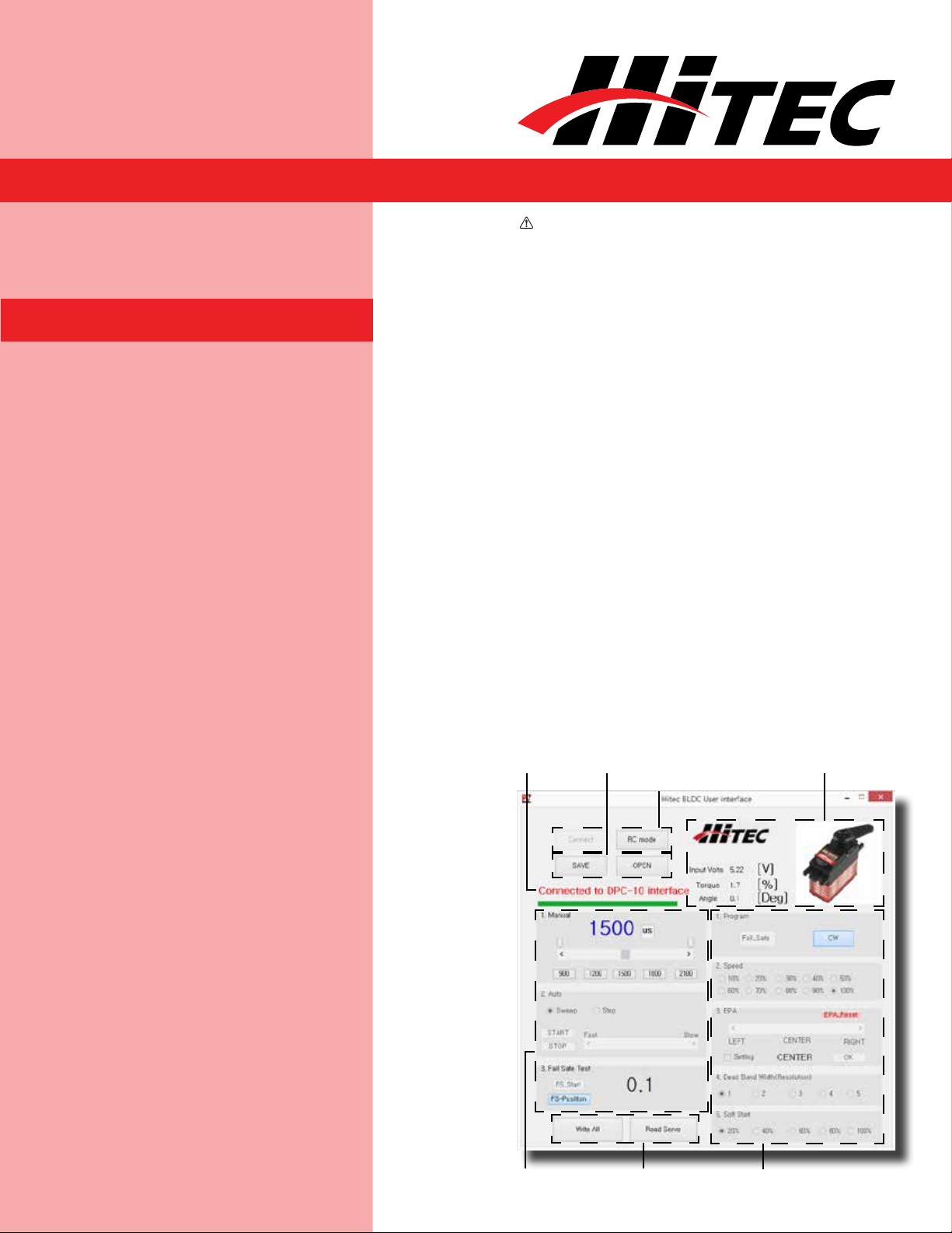
Connection
Indicators
File Operations
Buttons
Connection
Buttons
Servo
Information
2
Testing
Section
Write/Read
Buttons
Programming
Section
Page 3

DPC-10
Hitec Brushless Servo PC Programming Interface
DPC-10 Software Operating Manual
Programming Functions
Section 2
Connections
Basic Mode Connection
The following functions can be programmed into the
HITEC BLDC servos using the DPC-10:
1. FAIL SAFE, On or Off.
2. Direction of Rotation.
3. Travel Speed (Slower).
4. Center, End, and FAIL SAFE Point.
5. Dead Band Width.
6. Soft Start.
7. “Save and Open” Parameter File.
8. Load Factory Default Parameter File.
There are two ways to connect your servo to the
DPC-10, Basic Mode and RC Mode.
Basic mode connection allows you to control your
servo from your PC. All parameters are set first, then
loaded into the servo from your PC. Use your PC to
check the functions.
It is recommended that you connect your DPC-10 in
the following order for proper operation:
1. Connect DPC-10 to your PC computer.
2. Launch the DPC-10 software.
3. Connect your servo to the DPC-10 servo port.
4. Connect your battery to the DPC-10 battery port.
Now click the “Connect” button in the DPC-10
software. If your connections are correct, you will see
the following screen.
3
Page 4

DPC-10
Hitec Brushless Servo PC Programming Interface
DPC-10 Software Operating Manual
Basic Mode Connection
RC Mode Connection
RC Mode connection is useful when setting your
servo parameters because it allows you to check the
function with your radio just as if you were operating
your model. You will still need to use your PC to
perform the programming, but you will use your radio
to check the functions.
It is recommended that you connect your DPC-10 in
the following order for proper operation:
1. Make sure your receiver is bound to your
transmitter.
2. Connect DPC-10 to your PC computer.
3. Launch the DPC-10 software.
4. Connect your servo to the DPC-10.
5. Connect your receiver to the DPC-10 and turn on
the power.
6. Turn on your radio.
7. Click on the “Connect” button.
8. Click on “RC Mode.” Once connected, you will get a
message saying “RC mode change is complete.”
You can now operate the servo with your
transmitter.
4
Page 5

DPC-10
Hitec Brushless Servo PC Programming Interface
DPC-10 Software Operating Manual
Section 3
Using the DPC-10 Test Functions
Manual Position Test
Click on the Set Position Buttons or move the slide
bar with your mouse to manually move your servo’s
position.
Note: You can use the Endpoint Slide Bars bar to set
the end points for both auto sweep and auto step
functions as described below.
Left End
Point Adjuster
Set Position
Buttons
Position in µs
(900-2100)
Manual Slide Bar
Right End
Point Adjuster
Automatic Sweep Positioning Test
5
The “Auto-Sweep” function will cycle a servo over and
over from end point to end point.
1. Select Sweep on the menu and click the “START”
button. The servo will then move from end point to
end point within its travel limits.
2. Use the slide bar next to the “START/STOP”
buttons to adjust the servo’s travel speed.
3. Click “STOP” to end the process.
Page 6

DPC-10
Hitec Brushless Servo PC Programming Interface
DPC-10 Software Operating Manual
Automatic Step Positioning Test
1. Select “Step” and click the “START” button. Your
servo will start moving from end point to end point
in a series of small steps.
2. Use the slide bar next to the “START/STOP”
buttons to adjust the servo’s travel speed.
3. Click “STOP” to end the process.
Fail Safe Test
This feature tests the user programmed FAIL SAFE
point of your servo.
Note: The FAIL SAFE point must be set by the user
in the programming section under setting the FAIL
SAFE Point. By clicking the “FS-Position” button, the
servo will travel to its preset Fail Safe position.
Section 4
Programming Hitec Brushless Servos
6
The following functions can be programmed into
the HITEC BLDC servos using the DPC-10. It is
recommended that you program your servos in the
following order:
Page 7

DPC-10
Hitec Brushless Servo PC Programming Interface
DPC-10 Software Operating Manual
Programming Hitec Brushless Servos
Direction of Rotation
1. Direction of Rotation
2. Travel Speed (Slower)
3. Dead Band Width
4. Soft Start Percentage
5. Center and End Points
6. FAIL SAFE, On or Off
Note: To make your changes permanent you must
“write” the programming to the servo by clicking
the “WRITE ALL” button. You can do this after each
programming step or wait until you have finished all
programming.
Travel Speed
7
Normal servo rotation based on 900 - 2100µs input
signal is clockwise from left to right. You can change
this to counterclockwise by clicking on the Direction
of travel button as shown. The direction is shown as
CW for clockwise and CCW for counterclockwise.
This feature is useful for users who do not have
servo speed control functions on their transmitter.
Reducing the travel speed is a nice feature to slow
down aircraft landing gear retracts. The servo speed
Page 8

DPC-10
Hitec Brushless Servo PC Programming Interface
DPC-10 Software Operating Manual
Travel Speed
Dead Band Width
Soft Start Setting
function will only slow a servo down. You cannot make
a servo travel faster than its rated speed. You can
adjust the servo’s travel speed in ten proportional
steps from a minimum speed (10%) up to its
maximum speed (100%).
Some applications, such as using multiple servos on
a single control surface, may require you to change
the center “Dead Band” to prevent the servos from
fighting each other. Users can adjust the center
point “Dead Band Width” to one of five choices with 1
being the most sensitive and 5 the least sensitive.
Center and End Point
Adjustment Setting (EPA)
The soft start setting allows users to set how fast the
servos react when first powered on. Using a slower
soft start setting can prevent damage to your model
by slowly moving the servo into position. Default
setting is 20% (slowest). There are five settings from
20% to 100% which is an instantaneous reaction.
Note: This setting has no affect on the reaction
speed of the servo once it is powered up.
With the EPA setup, users can customize the center
point and left/right servo travel end points. This can
be helpful to fine tune your model’s control surfaces.
To set the Center and Endpoints, click on the
“Setting” box under the EPA programming section.
8
Page 9

DPC-10
Hitec Brushless Servo PC Programming Interface
DPC-10 Software Operating Manual
Center and End Point
Adjustment Setting (EPA)
NOTE: The numbers represented in
the EPA adjustments are shown as
percentages. With center at 0 and left
and right endpoints at 100%, the servo
will move approximately 100 degrees in
each direction. It should also be noted
that the left and right adjustment values
will change if the center point is adjusted.
The first setting is the center point. If you don’t want
to change the center point, click “skip” otherwise
you can adjust the center point using three different
methods.
1. Click on and move the slide in the adjustment bar
to move in larger steps.
2. Click the arrows “< >” on each end to make the
smallest adjustments.
3. Click on the white space of the adjustment bar to
move it in 10 point increments.
When you have reached your desired center point,
press “OK” to continue. Now you will set up the left
and right end points. Click “OK” when prompted by
the pop-up screens. The left and right end points are
adjusted in same manner as the center points with
the exception that clicking on the white space of the
adjustment bar results in movements of 10 point
increments and clicking the < and > arrows move in
increments of 0.5%. Once you have set your left end
points click “OK” to set the right end points then click
“OK” again to complete the EPA setup process.
9
Page 10

DPC-10
Hitec Brushless Servo PC Programming Interface
DPC-10 Software Operating Manual
Center and End Point
Adjustment Setting (EPA)
Resetting EPAs
10
To reset your EPAs to the factory defaults click
on the “Setting” box under the EPA programming
section. Then click “EPA_Reset.”
Page 11

DPC-10
WARNING
WARNING
Hitec Brushless Servo PC Programming Interface
DPC-10 Software Operating Manual
Resetting EPAs
Fail Safe Position
By choosing to use the Fail Safe function you will need
to set a preprogrammed travel point that the servo
will travel to in the event the servo loses signal from
the receiver.
WARNING – Program the Fail Safe point after
setting the end and center points otherwise it will
change when you make those settings.
To set the Fail Safe point first, click on the “Fail Safe”
under the Program section.
Next move your servo to the desired position by using
the Manual positioning section as shown. You can
use any of the preset points or you can move it in one
of three other ways, either in 1µs steps by clicking
on the arrows “< - >”, in 50µs steps by clicking on the
white space of the adjustment bar or with the slide in
the adjustment bar.
11
Once you have your desired Fail Safe position, click on
the FS-Position button Fail Safe Test as seen in the
illustration.
Page 12

DPC-10
Hitec Brushless Servo PC Programming Interface
DPC-10 Software Operating Manual
Fail Safe Position
Section 5
Note: Remember to “Write All” your settings to your
servo before closing the DPC-10 software and dis-
connecting your servo. Failure to do so will result in
the loss of your programmed settings.
Saving and Loading Files/
Restoring Default Files
Saving Files
With the DPC-10 software you have the ability to
save and load servo parameter files. This is helpful
when needing to set up multiple servos with the
same parameters. The DPC-10 software also has
the ability to restore the factory defaults file in the
event the user setup doesn’t operate correctly. The
following details how to use these features.
Once you have completed your servo setup and
written the setup to the servo, click on “Read Servo.”
Next click on “SAVE” to open the save file dialog box.
Navigate to the location that you want to save your
file to, enter a name for your servo and click “Save.”
You have successfully saved your servo parameters
to a file.
Loading Files
12
To load a parameter file click on “OPEN”, navigate
to the location where you stored your file and click
“Open.” You will get the “File load has completed”
prompt. Click “OK.” Now click “Write All” to load the
setting onto the servo. Once you get the “Write All
Page 13

DPC-10
WARNING
WARNING
Hitec Brushless Servo PC Programming Interface
DPC-10 Software Operating Manual
Loading Files
Restoring Factory Defaults To restore the servo to the factory default
completed” message, click “OK.” The parameters
have been written to the servo.
setting, click on “OPEN” and navigate to the
directory where you unzipped the DPC-10
software download. In the directory “Factory
Defaults,” you will find the files for each servo
model. Click on the file that matches the servo
you want to restore and click on “Open.” Once
you get the file load has completed message,
click “OK.” Now click “Write All” to load the
setting onto the servo. Once you get the Write
All completed message, click “OK.” The default
parameters have been written to the servo.
Help is available from the Hitec office
through phone support and e-mail. Our US
office is generally open Monday thru Friday,
8:00AM to 4:30PM PST.
Phone: (858) 748 - 8440
E-mail: service@hitecrcd.com
Web: www.hitecrcd.com
13
WARNING – Restoring a factory default file other
than the one specifically made for your servo may
result in undesired operation.
 Loading...