

Page 1
CP5220 Submersible
Level Transmitter for Tank
Serial n€ :
Nominal range :
Cable length : 10 meters +
GENERAL FEATURES
Water level measurement, control and process for tanks and water towers.
TECHNICAL PRINCIPLE
The level measurement is performed through the differential pressure measurement between liquid surface and the submersible sensor. The pressure is
converted into electric signal by piezo-electric gauge to provide a 4/20mA output signal on 2 wires.
MECHANICAL SPECIFICATIONS
Housing : Stainless steel 316L, PVC tip
Cable : 2 wires + internal tube in shielded PVC (food approval)
cable
Sensor : piezo-resistive gauge with silicone coating.
Diameter : 31 mm
Height : 150 mm (without cable)
Weight : 435 g (without cable) Supplied normally with 10 meters
of shielded cable (475 g) or more upon request
Fitting : by the suspension cable supplied with a hanging system
KITCAB.
ELECTRICAL SPECIFICATIONS
Output signal : 4/20mA output signal on 2 loop wires, 4mA for 0m and
20mA for the full-scale
Power supply : Voltage supply between 6 to 38 volts DC input. (Don’t for-
get to integrate the voltage drop-out in the current loop)
Check the voltage specification of the protector unit
EMC Conformity : EN 50 081-2, EN 50 082-2
Consumption : the signal value (mA)
TECHNICAL DATA
Water column range : Full-scale (F.S.) between 0,5 m to 30m. (Full-scale 20mA
adjusted to the required value by Hitec)
Equivalent pressure : 0,05 to 3 bars. P(bars) = H(meters) / 10.197
Hysteresis : 0,10 % F.S. (constant temperature).
Non-linearity : 0,15 % F.S. (constant temperature).
Temperature operating range : from 2€C to 50€ Celsius
CP5220 / Data sheet / release.A2 - Page 1 of 2
Page 2
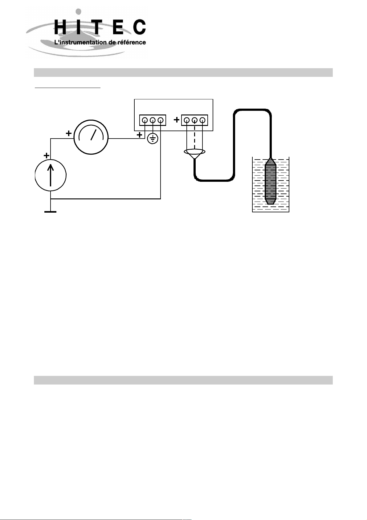
USING INSTRUCTIONS
Electrical connections:
CP5220 Submersible
Level Transmitter for Tank
PSE30V
Display
Line Transmitter
white
mA
wire
Power supply
27Vdc max.
(38Vdc max with PSE43V)
*
earth ground for
EMI / RFI protection.
The operating instructions are very easy. No
need signal adjustment (fitted in laboratory)
The cable is fitted with an internal small tube
for atmospheric pressure compensation. Don’t
block or pressure the tube. Don’t put the end
of the cable in water or flooding area during
the installation, check the correct position of
the cable without dangerous roughness or
sharpness. Don’t use any sharp tool for fitting:
risk of water infiltration.
blue
wire
*
connect shield to
Connect the lightning protector (PSE30V) on a
very good earth line. Provide a power voltage
supply sufficient to compensate the drop-out
in the current loop and be sure to get a 6VDC
minima on the transmitter : Measure the total
electrical resistance of the line (included all
electronic systems) and apply the following
formula :
U (supply mini) = 6V + (R line x 0.02 A).
In the most cases, a 12 or 24 VDC supply is
sufficient
Check the correct polarity of the connections :
the inversion of polarity is not destructive; in
this case, the signal drops to 0mA.
Warning : Following the lightning protector
unit fitted with the transmitter, PSE43V or
PSE30V, the power voltage max. is 38V for
PSE43V and 27V for PSE30V.
TROUBLE-SHOOTING PROCEDURE
Transmitter checking : Disconnect the transmitter from the system ; Connect the transmitter on a
battery (12VDC or small square 9VDC battery) and introduce a milli-amperemeter in the loop.
Check the current value : 4mA with the transmitter out of water and atmospheric pressure, and
20mA for the full-scale height of water.
For intermediate value : H (meter) = (Signal (mA) - 4mA) x F.S. (meter) / 16,
and conversely : Signal (mA) = ((Height (m) / F.S. (m)) x 16) + 4mA
CP5220 / Data sheet / release.A2 - Page 2 of 2
 Loading...