

Page 1

ADD: Building13, Tian’An Technology Zone HQ center, No.555, the North of Panyu RD, Panyu District 511400, Guangzhou, China.
VNet6 Plus User Guide
Hi-Target Surveying Instrument Co., Ltd.
All Rights Reserved
Page 2

ADD: Building13, Tian’An Technology Zone HQ center, No.555, the North of Panyu RD, Panyu District 511400, Guangzhou, China.
Manual Revision
File number:
Revision
Date
Revision Level
Description
2017-06-19
1
VNet6 Plus User Guide
Page 3
ADD: Building13, Tian’An Technology Zone HQ center, No.555, the North of Panyu RD, Panyu District 511400, Guangzhou, China.
Preface
Introduction
Welcome to VNet6 Plus User Guide. This introduction describes how to use this
product.
Experience Requirement
In order to help you use Hi-Target series products better, Hi-Target suggests you
carefully read the instruction. If you are unfamiliar with the products, please refer
to www.hi-target.com.cn or contact Hi-Target Technical Group.
Tips for safety use
Notice: The contents here generally are special operations, and
need your special attention. Please read the contents carefully.
Exclusion
Before using the products, please carefully read the operating instruction, and it
will help you better use it. Hi-Target Surveying Instrument Co., Ltd will not assume
the responsibilities if you fail to operate the product according to the requirements
in operating instruction, or operate the product wrongly because of failing to
understand the operating instruction.
Warning: The contents here generally are very important. Such
wrong operation may make the machine damaged, make the data lost, even
breaks down the system and endangers personal safety.
Page 4

ADD: Building13, Tian’An Technology Zone HQ center, No.555, the North of Panyu RD, Panyu District 511400, Guangzhou, China.
Hi-Target is committed to constantly perfect product functions and performance,
improve service quality and reserve the rights to change the contents in operating
instruction without separate notice.
We have checked the consistency between contents in instruction and software &
hardware, without eliminating the possibility of deviation. The pictures in
operating instruction are only used for reference. In case of inconformity with
products, the products shall prevail.
Technology and Service
If you have any technical issues, you can call Hi-Target technology department for
help, we will answer your question in time.
Advice
If you have any comments and suggestions, please call us or Dial the national
hotline: +86 400-678-6690. Your feedback information will help us to improve the
quality of the product and service.
Page 5

ADD: Building13, Tian’An Technology Zone HQ center, No.555, the North of Panyu RD, Panyu District 511400, Guangzhou, China.
Vnet6 Plus User Manual
Chapter1 Introduction ................................................................................................................ 7
1.1 Introduction .......................................................................................................................... 7
1.2 Features ................................................................................................................................ 8
1.3 Use and precautions ........................................................................................................... 10
Chapter 2 GNSS receiver Introduction ................................................................................... 13
2.1 Front Panel ......................................................................................................................... 13
2.2 Back Panel ......................................................................................................................... 14
2.3 Mainframe .......................................................................................................................... 14
2.4 Button Function ................................................................................................................. 15
2.5 Indicator lights ................................................................................................................... 16
2.6 LCD ................................................................................................................................... 17
2.7 External port ...................................................................................................................... 20
Chapter 3 WEB Administration .............................................................................................. 22
3.1 User login ........................................................................................................................... 22
3.2 WEB interface for administration ...................................................................................... 24
3.3 Elementary info ................................................................................................................. 25
3.4 Home page ......................................................................................................................... 26
3.5 System info ........................................................................................................................ 27
3.6 working mode .................................................................................................................... 30
3.7 File management ................................................................................................................ 39
3.8 Advanced setting ................................................................................................................ 42
3.9 User management .............................................................................................................. 51
Chapter 4 Basic operations ....................................................................................................... 53
4.1 Architecture model ............................................................................................................. 53
4.2 Basic composition and connection .................................................................................... 53
4.3 Connector installation ........................................................................................................ 54
4.4 Network connection ........................................................................................................... 56
4.5 LCD and button operation ................................................................................................. 62
4.6 Set the base station ............................................................................................................. 64
4.7 Add data record .................................................................................................................. 66
4.8 Add network transmission ................................................................................................. 68
Page 6

ADD: Building13, Tian’An Technology Zone HQ center, No.555, the North of Panyu RD, Panyu District 511400, Guangzhou, China.
4.9 Data download ................................................................................................................... 70
4.10 Firmware upgrade ............................................................................................................ 73
4.11 Register the receiver ........................................................................................................ 75
Chapter 5 Appendix .................................................................................................................. 78
5.1 Reset .................................................................................................................................. 78
5.2 VNet product technical performance parameters table ...................................................... 79
5.3 Standard configuration table .............................................................................................. 80
Page 7

Surveying the world,Mapping the future.
ADD: Building13, Tian’An Technology Zone HQ center, No.555, the North of Panyu RD, Panyu District 511400, Guangzhou,
China.
Chapter1 Introduction
1.1 Introduction
HI TAGET GNSS receiver VNet series (referred to as "receiver" or "GNSS
receiver") products include: VNet6, VNet6 Plus, VNet8 and so on. This
manual mainly introducing GNSS receiver VNet6 Plus.
The VNet Series GNSS reference receiver installed with the high-
performance microprocessors, high-capacity, high-speed flash memory
and battery, multi-communication port and military grade industrial
standard design level. With built-in firewall, data encryption transmission
protocol, make the GNSS receiver more accurate, easy to use , better
availability, more stable operation. On the strength of Hi-Target’s
sophisticated GNSS technology and the years of experiences in
establishing CORS/VRS system, the VNet series GNSS reference receiver
will provide you with reliable communication, better performance,
stronger stability and safety.
Notice:
1. The specific configuration is write on the list.
2. Please carefully open the box to confirm. If you find any loss
of this product and accessories, damages, please contact your
local office or dealer immediately.
3. Please read the instruction manual carefully before carrying,
using and handling.
Page 8

Surveying the world,Mapping the future.
ADD: Building13, Tian’An Technology Zone HQ center, No.555, the North of Panyu RD, Panyu District 511400, Guangzhou,
China.
1.2 Features
1.Based on the Linux operating system
Based on the embedded Linux operating system kernel, is a real multi-user,
multi-tasking, multi-platform operating system. With its system stability,
management functions, powerful network; the Vnet6 Plus is suitable for a
long time unattended continuous work.
2. Excellent GNSS multi-constellation tracking performance
220 Channels with Trimble OEM mainboard, support GPS, GLONASS,
BDS, GALILEO and other global satellite navigation and positioning
system, can maximize the tracking ability of all visible GNSS satellite
signals, thereby improving the measurement accuracy and real-time RTK
measurement performance.
3. 50 Hz updating rate
Support high frequency data updating, data updating rate up to 50 Hz, and
maintain the best observation quality of the data and the independence of
the observation value;
4.Multi-task function
The GNSS receiver can deal with multiple task operations at the same time
and simultaneously download, release different types of RTK or RTD data
while continuously tracking and recording satellite data.
5. Multi transmission mode
With UHF radio, data line Modem, broadband port, Fax Modem, TCP / IP,
Page 9

Surveying the world,Mapping the future.
ADD: Building13, Tian’An Technology Zone HQ center, No.555, the North of Panyu RD, Panyu District 511400, Guangzhou,
China.
built-in 3G / 2G wireless communication function, can use the Internet,
wireless network for data transmission and broadcast differential data.
6.Massive data management function
Built-in 64GB high-performance storage and can support the maximum of
less than 1TB industrial-grade U disk storage or external USB storage
devices; support U disk download, FTP download and remote download;
and the receiver also has a loop storage function.
7.High-precision measurement technology
The Hi-Target’s sophisticated GNSS technology make sure the accuracy
reaches millimeter, make sure the data have the reliable quality.
8. Excellent compatibility
With excellent compatibility, real-time output CMR, RTCM, RTCMV3,
RTCM32, and other formats of correction data to compatible with third
part CORS system seamlessly, which can be used to new and extend
enhance CORS system. Also output high-precision real-time GNSS raw
data.
9. Remote access function
Easy to using the Network for remote access the reference stations, easy
for remote control.
10. Multi data interface
Equipped with three RS232 ports, two USB ports, one Wi-Fi, one
Bluetooth communication port, one 3G / 2G communication port, one
Page 10

Surveying the world,Mapping the future.
ADD: Building13, Tian’An Technology Zone HQ center, No.555, the North of Panyu RD, Panyu District 511400, Guangzhou,
China.
Ethernet port, one RS485 port, one external clock port, one PPS output port,
fully meet the reference Station requirements.
11.Multi-mode power supply
Built-in large capacity lithium battery, can work for 24 hours (related to
configuration); external voltage power supply: 7VDC ~ 36VDC; support
battery, solar and wind power supply.
1.3 Use and precautions
Although the VNet series (ground-based) GNSS receiver is based on
military standard design, it is anodized with an aluminum alloy, but the
precision instruments require careful use and maintenance.
WARNING: The receiver must be used and stored within
the specified environment. Please refer to the Appendix:
VNet product technical performance parameters table.
Avoid using the receiver in extreme environments.
The VNet6 Plus (ground-reinforced) GNSS receiver uses anodized
aluminum alloy for the shell, but should also be kept as dry as possible.
And in order to improve the stability of the receiver and extend the service
life, please avoid the receiver exposed to extreme environments, such as:
1. Damp
2. The temperature is higher than 75 ℃
3. The temperature is less than -40℃
4. Corrosive liquid or gas
Page 11
Surveying the world,Mapping the future.
ADD: Building13, Tian’An Technology Zone HQ center, No.555, the North of Panyu RD, Panyu District 511400, Guangzhou,
China.
Do not place the GNSS antenna near sources of electricity and strong
interfering signals:
1. Oil (spark plug)
2. TV and computer monitors
3. Generator
4. Electric motorcycle
5. DC - AC power conversion equipment
6. Fluorescent light
7. Power switch
When selecting the position of the GNSS reference station for continuous
operation, notice the following:
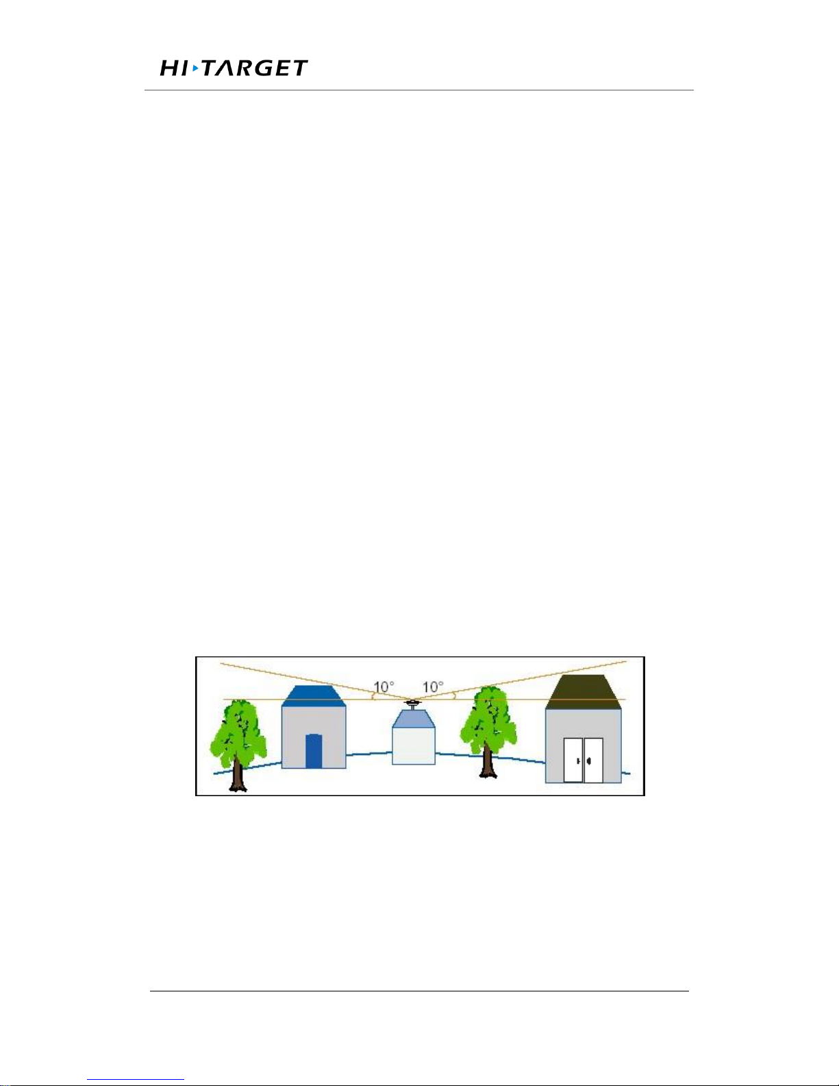
The site should be easy to place the receiving device and have a wide field
of vision. Field height above 10 degrees should not have obstacles, so as
not to absorb or block the GNSS signal, as shown in Figure 1-1:
Figure 1-1
1.Near the site should avoid the large area of water or strong interference
with the satellite signal, to reduce the impact of multi-path effect.
2.The site should be away from high-power radio transmission sources
(such as television stations, microwave stations, etc.,) it's better to keep a
Page 12

Surveying the world,Mapping the future.
ADD: Building13, Tian’An Technology Zone HQ center, No.555, the North of Panyu RD, Panyu District 511400, Guangzhou,
China.
distance more than 200m; away from high-voltage transmission lines, the
distance should more than 50m to avoid electromagnetic interference on
the GNSS signal.
3.To provide a stable device to fix the antenna.
4.To provide reliable and stable power supply and communication network.
5. Suitable placement and protection of GNSS reference station equipment.
6.Select the traffic developed place, easy to arrive for inspection and
maintenance.
Page 13
Surveying the world,Mapping the future.
ADD: Building13, Tian’An Technology Zone HQ center, No.555, the North of Panyu RD, Panyu District 511400, Guangzhou,
China.
Chapter 2 GNSS receiver Introduction
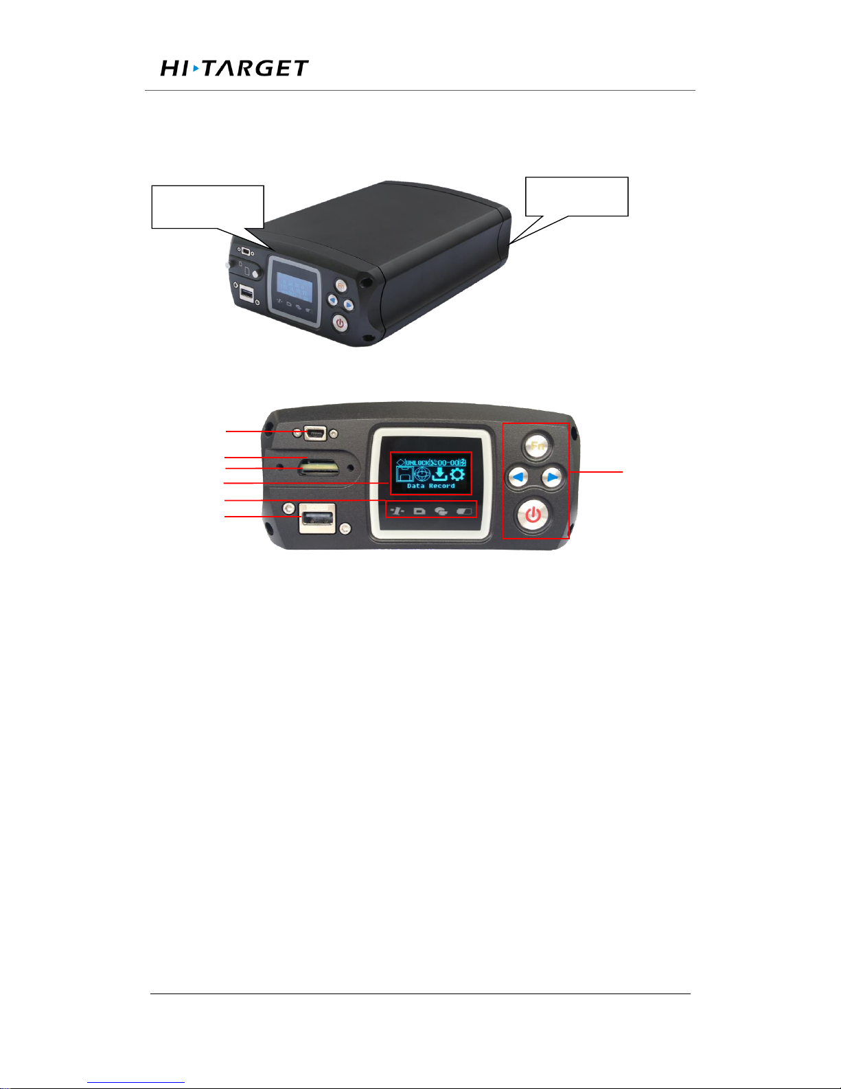
2.1 Front Panel
Figure 2-1 Overall appearance of the receiver
Figure 2-2 Front panel
1. MiniUSB port: Reserved
2.TF Card slot:Install TF(micro SD) card to Expand storage capacity
3.SIM Card slot:Install standard SIM card for 3G / 2G wireless network
communication
4.LCD: Display receiver status information
5.Indicator light:Indicates information such as receiver tracking status,
network status, power status, and so on
6.USB port:Connect a USB flash drive or USB storage device for storing
/ downloading data and upgrading the firmware
7. Button panel: For query and configure the receiver.
Front Panel
Back Panel
1
2
3
4
5
6
7
Page 14
Surveying the world,Mapping the future.
ADD: Building13, Tian’An Technology Zone HQ center, No.555, the North of Panyu RD, Panyu District 511400, Guangzhou,
China.
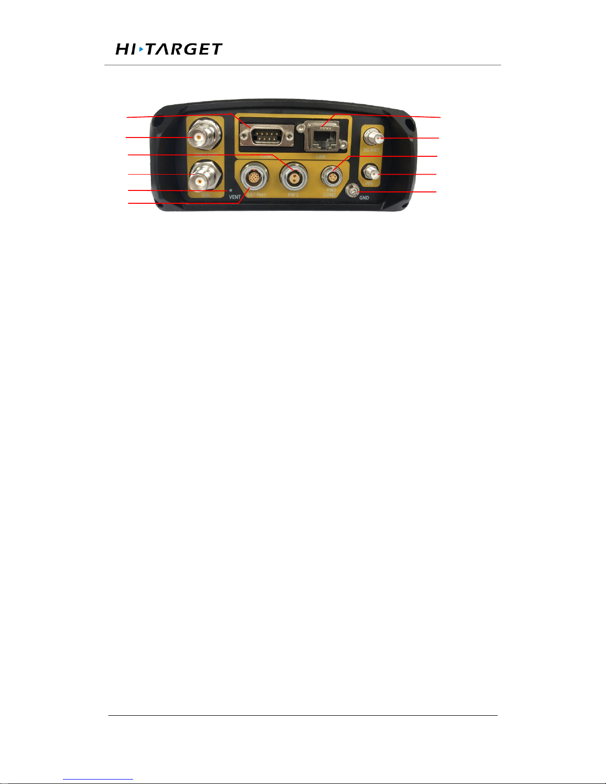
2.2 Back Panel
Figure 2-3 back panel
1.DB9 port: Data output and connect to external devices
2.GNSS antenna: For connect the antenna
3.Power port: Power input port
4. External clock: TNC Socket for connecting external atomic clocks
5. Ventilation holes: Waterproof ventilation holes
6.External extension:12V DC power output, RS232 debugging port,
RS485/RS422 Communication port, hardware restart port
7.LAN port:Wire network connection port
8.3G antenna: Connect the 3G / GPRS antenna port
9.Five-core socket: Differential data output, external data link connection;
auxiliary power supply input
10.PPS output: PPS output port
11.Ground Point: Lighting protection grounding port
2.3 Mainframe
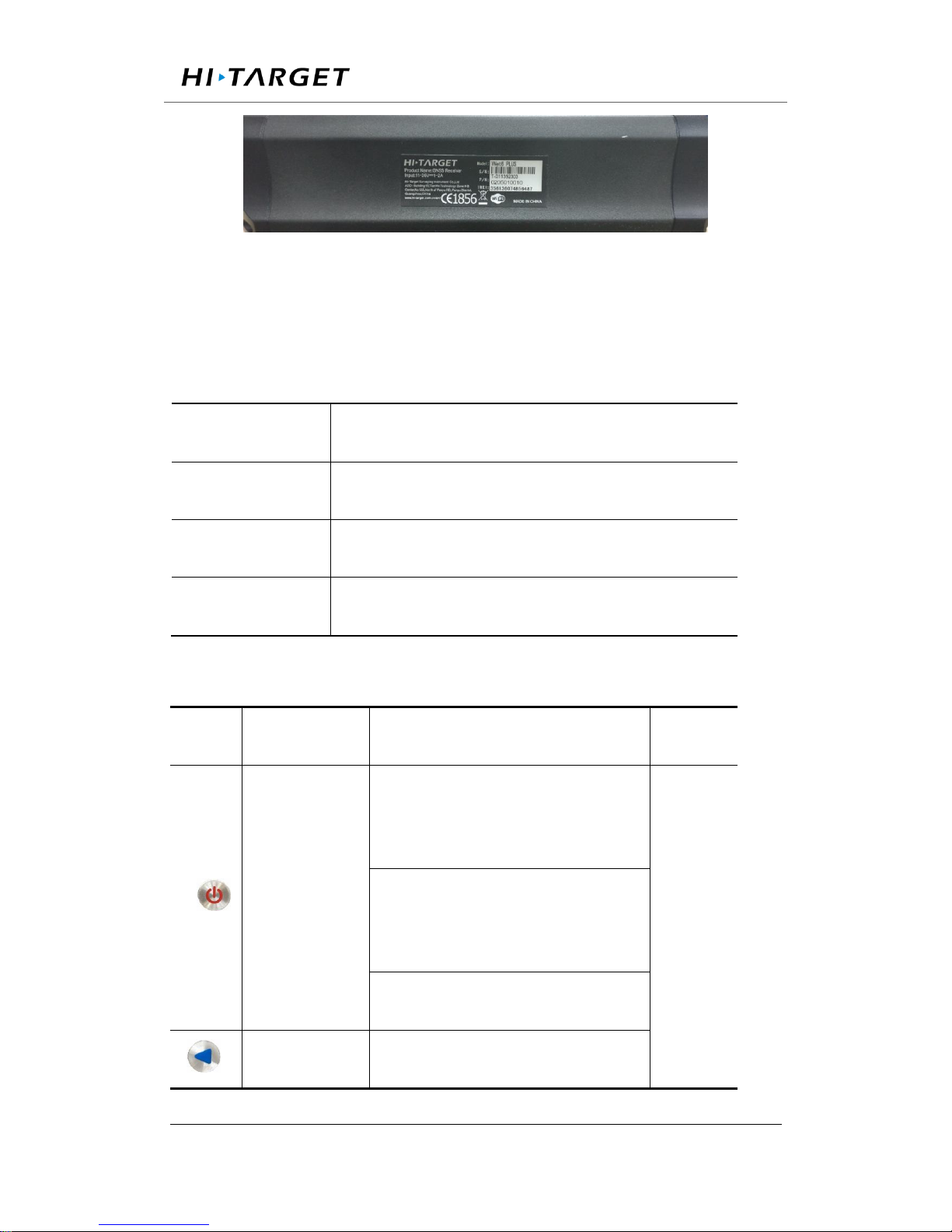
The mainframe uses an all-aluminum alloy metal housing and uses an
anodizing process, as shown in Figure 2-4:
4
5
6
10
11
9
8
7
3
2
1
Page 15
Surveying the world,Mapping the future.
ADD: Building13, Tian’An Technology Zone HQ center, No.555, the North of Panyu RD, Panyu District 511400, Guangzhou,
China.
Figure 2-4 Mainframe
2.4 Button Function
Table 2.1 Button Description
Operation
Description
Click
button operation< 0.5 s
Double Click
button operation interval <1 s
Long Press
button operation>6 s
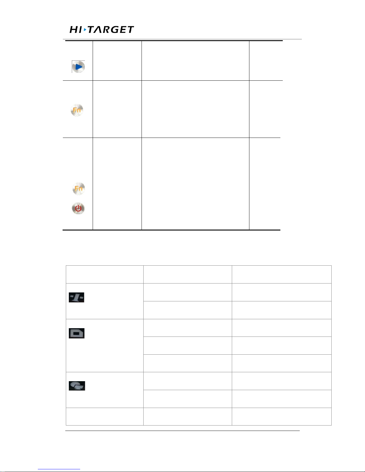
Table 2.2 Button Function Description
Button
Name
Function
status
Power button
Double-click:turns off / on the
LCD
See in
the LCD
Single click:Boots, modify the
parameters and confirm
Long Press:turn off
Left button
Single click:Move left or up
Page 16
Surveying the world,Mapping the future.
ADD: Building13, Tian’An Technology Zone HQ center, No.555, the North of Panyu RD, Panyu District 511400, Guangzhou,
China.
Right button
Single click : Move right or
down
Function
Button
Cancels or interface switch
See in
the
LCD
Combination
Button
Press the Fn button and click
the power button To upgrade
the kernel;
The
satellite
lights
are
flashing
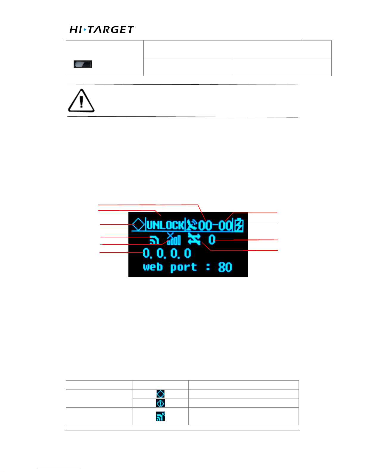
2.5 Indicator lights
LCD information
Status
Function
Satellite light
Always bright
Satellite tracked
Always off
Satellite untracking
Record light
Quick flashing
Record interval <1 second
Slow flashing
Recording interval≥1 s
Always off
Recording stops
Network light
Always bright
Connected
Always off
No network connection
Quick flashing red
Alarm
Page 17
Surveying the world,Mapping the future.
ADD: Building13, Tian’An Technology Zone HQ center, No.555, the North of Panyu RD, Panyu District 511400, Guangzhou,
China.
Power / Alarm Light
Always yellow
External power supply
Always green
Battery powered
Notice: double-click the power button to open the LCD display,
the lights will turn off except for the network light.
2.6 LCD
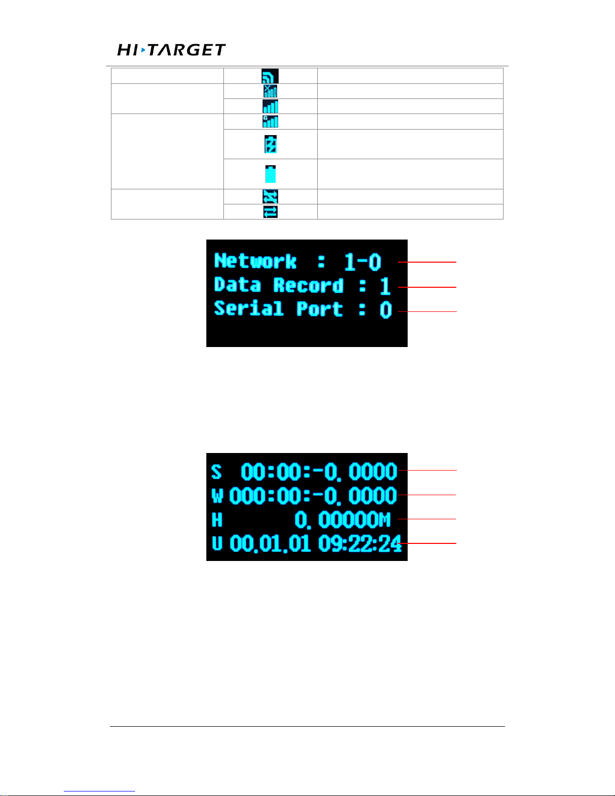
Status display normally will show the Status of satellites, IP, port and
Network connection status.
1.Status Display
Figure 2-5 Main parameter information
1-Common satellite Number; 2-satellite Lock Status;3-Alarm
Status;4 - Wi-Fi Status; 5-3G Network Status; 6-IP Address; 7-Total
satellite number ;8-Power supply / battery power; 9-3G Signal
strength;10-3G Network transmission status;
LCD status
Shows
meaning
Alarm status
Normal status
Alarm
Wi-Fi status
Wi-Fi is off
1
2
3
4
5
6
7
8 9 10
Page 18
Surveying the world,Mapping the future.
ADD: Building13, Tian’An Technology Zone HQ center, No.555, the North of Panyu RD, Panyu District 511400, Guangzhou,
China.
Wi-Fi is on
3G network status
The 3G module is off
The 3G module is on
3G network status
Power supply
Connected to a public network
External power supply
Battery powered
3G network
transmission status
No data transmission
Data transmission
Figure 2-6 Data transfer status
1- Total network stream– Enabled network stream; 2- Enabled data record
stream; 3- Enabled serial port number
Figure 2-7 Coordinate information
1 Latitude -;2- Longitude;3-Elevation;4-UTC time
1 3 2
1 2 3
4
Page 19
Surveying the world,Mapping the future.
ADD: Building13, Tian’An Technology Zone HQ center, No.555, the North of Panyu RD, Panyu District 511400, Guangzhou,
China.
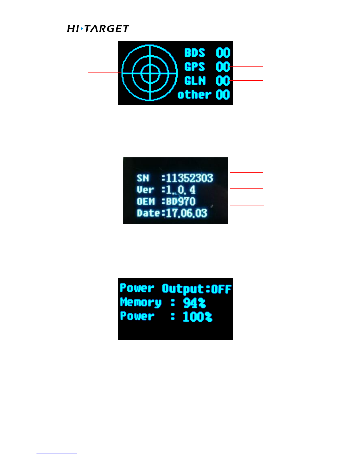
Figure 2-8 Satellite information
1-Satellite number of BDS;2- Satellite number of GPS;3- Satellite number
of GLONASS;4- Satellite number of other;5- Satellite map of the sky
Figure 2-9 Receiver status information
1-Receiver SN number;2-Version;3-Motherboard version;4-Expire data;
Figure 2-10 Status information
2.Display setting
1 2 3 4 5 4 1
2
3
Page 20
Surveying the world,Mapping the future.
ADD: Building13, Tian’An Technology Zone HQ center, No.555, the North of Panyu RD, Panyu District 511400, Guangzhou,
China.
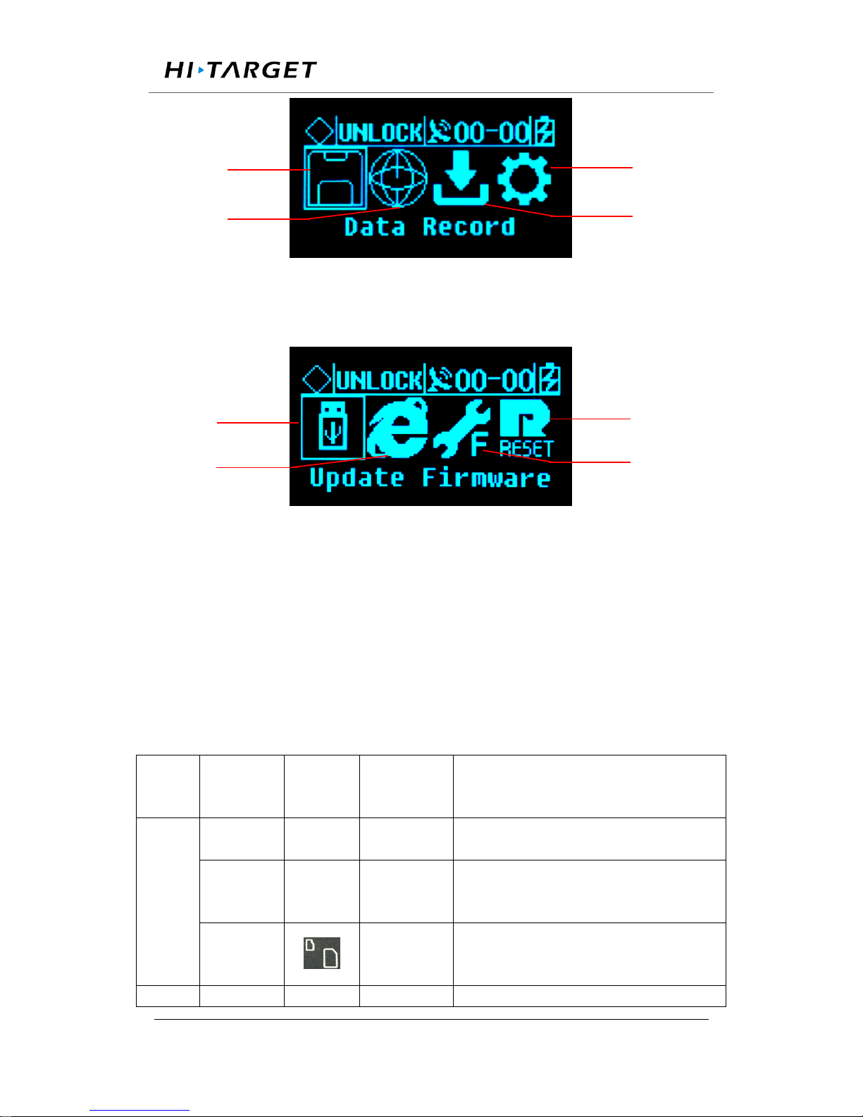
Figure 2-11 Setup menu
1- Data record;2- Network settings;3- Data download;4- System settings;
Figure 2-12 System settings
1- Firmware Upgrade;2- Restore the default IP;3- reset;4- Reset the
motherboard;
2.7 External port
Table 2.5 External port descriptions
Panel
Panel
Name
Panel
instructi-
ons
Physical
port
Function
Front
Panel
MiniUSB
port
/
MiniUSB
/
USB port
/
USB-A
Data storage / download, upgrade
firmware ,available for U disk and USB
removable storage
TF/
SIM Card
slot
TF/SIM
Card slot
TF card: storage data and ROM; SIM
card: 3G / 2G wireless network
communication;
Back
GNSS
GNSS
TNC
Connect the GNSS antenna
4
3 1 2 1 2
4
3
Page 21

Surveying the world,Mapping the future.
ADD: Building13, Tian’An Technology Zone HQ center, No.555, the North of Panyu RD, Panyu District 511400, Guangzhou,
China.
Panel
antenna
ANT
External
clock
input
OSC
TNC
Connect with external atomic clock
3G
antenna
3G ANT
SMA
Connect the 3G / GPRS antenna
PPS
output
PPS
SMA
PPS seconds pulse output
DB9
Serial port
COM1
DB9
GNSS data output and external sensor
access port
LAN port
LAN
RJ45
Wired access to local area networks,
support 10M/100M
External
extension
EXT
Port
Fourteen
core port
(LEMO)
RS485: GNSS data output and external
sensor access;
RS232: debug serial port;
EX12: 12VDC output;
PW_RST: hardware reboot;
EVT: external event input (reserved);
power
input
PW1
Two core
port
(LEMO)
Main power supply input;
Five-
core
socket
PW2
COM2
Small five
core port
(LEMO)
Auxiliary power supply input;
Differential data output;
Ground
point
GND
/
Grounding lightning protection
interface
Page 22

Surveying the world,Mapping the future.
ADD: Building13, Tian’An Technology Zone HQ center, No.555, the North of Panyu RD, Panyu District 511400, Guangzhou,
China.
Chapter 3 WEB Administration
3.1 User login
After network setting, GNSS receiver can be remote access in LAN or
WWW through the IP Address.
For the convenience of management, all users are categorized into three
groups.
A. Guest: users can log in without the enter of ID and password. They are
authorized to basic status check only.
B. Normal users: Must provide ID and password to log in, being
authorized to check system status, change parameters, browse, download,
and delete data file. Users are prioritized while the amount of online users
reach the maximum supported.
C. Administrator: Must log in with ID and password. Holding the highest
level of authority and able to add, delete accounts and change password of
other users. It is prioritized while the amount of online users reach the
maximum supported.
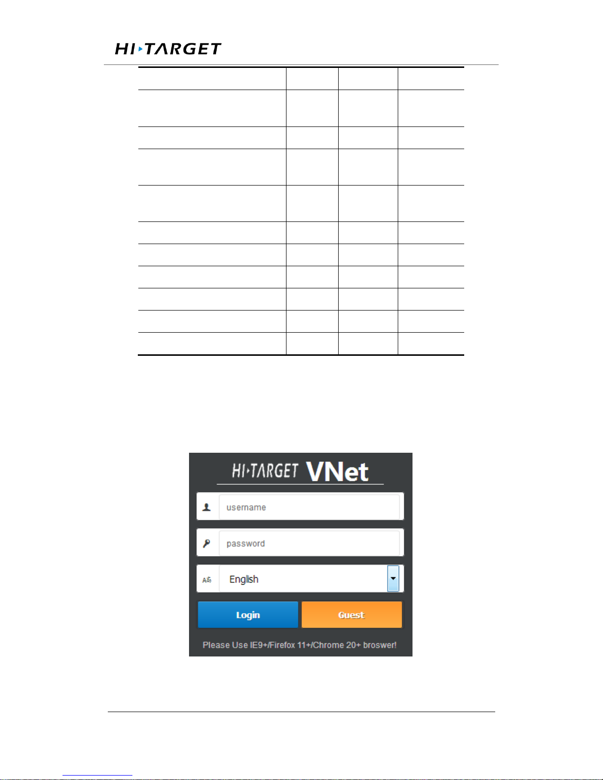
Table 3.1 authority class with different user groups
Authority
Guest
Normal
user
Administrat
or
Check status
○ ○ ○
Check position info and
satellite status
○ ○ ○
Check logging file
○ ○ ○
Check data transmission status
○ ○ ○
Page 23
Surveying the world,Mapping the future.
ADD: Building13, Tian’An Technology Zone HQ center, No.555, the North of Panyu RD, Panyu District 511400, Guangzhou,
China.
Modify configuration
× ○ ○
Set coordinate system and
observation parameters
× ○ ○
Control and modify log files
× ○ ○
Download or delete
observation file
× ○ ○
Modify data output
configuration
× ○ ○
Modify password
× ○ ○
Add or delete account
× × ○
Disconnect other user
× × ○
Restart the system
× × ○
Restart the device
× × ○
Upgrading OS and Apps
× × ○
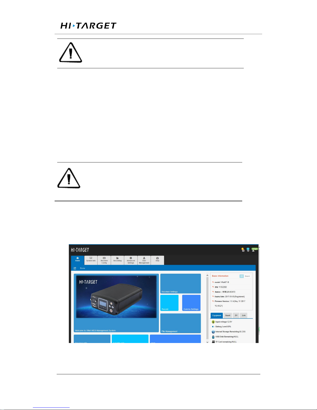
When accessing the WEB administration page of VNet, a login page would
show as the figure 3-1 below.
Figure 3-1. Login interface
Page 24
Surveying the world,Mapping the future.
ADD: Building13, Tian’An Technology Zone HQ center, No.555, the North of Panyu RD, Panyu District 511400, Guangzhou,
China.
Note:WEB administration of VNet series support PC, server, tablet,
smart phone, etc. Please use IE 9+/Firefox 11+/Chrome 20+ to
access the WEB system.
Input ID and password and click【log in】to enter the WEB system. Or just
click 【Guest】to log in as guest with elementary authority.
After initialization, the system creates an administrator account
automatically with username ‘zhdgps’ and password ‘zhdgps’ (exclude
quotation marks). Normal user accounts could be created by administrator
for the benefit of user management with different authority level.
Note:only one administrator account is allowed and password can be
changed. If you forget the password, please contact with Hi-Target
for administrator account or contact with administrator for normal
users’ password reset.
3.2 WEB interface for administration
Web interface including Home page, System info, Receiver settings,
Record and File management etc. Detail information see below pictures.
Figure 3-2. WEB interface
Page 25
Surveying the world,Mapping the future.
ADD: Building13, Tian’An Technology Zone HQ center, No.555, the North of Panyu RD, Panyu District 511400, Guangzhou,
China.
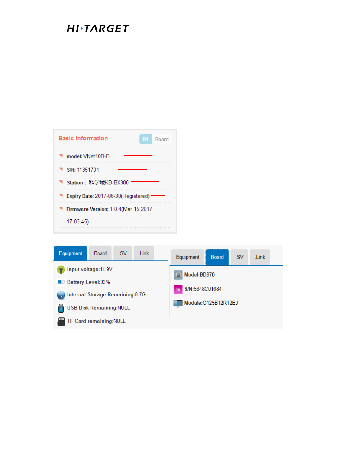
3.3 Elementary info
This sector located on the right hand part of WEB interface with the display
of instrument ID of receiver, firmware version, registration, instrument
status, motherboard info, amount of observing satellite, communication of
receivers, etc.
Receiver model with suffix.
SN, display in red when registration code expires.
Current station, revisable in Advanced setting/ System setting
Registration status and valid time
Page 26
Surveying the world,Mapping the future.
ADD: Building13, Tian’An Technology Zone HQ center, No.555, the North of Panyu RD, Panyu District 511400, Guangzhou,
China.
Figure 3-3 Basic information
Note:system limits the display of satellite amount and data transmission for
unregistered GNSS receiver and expired registration code. To prevent this
inconvenience, please contact with Hi-Target for new code before it
expires.
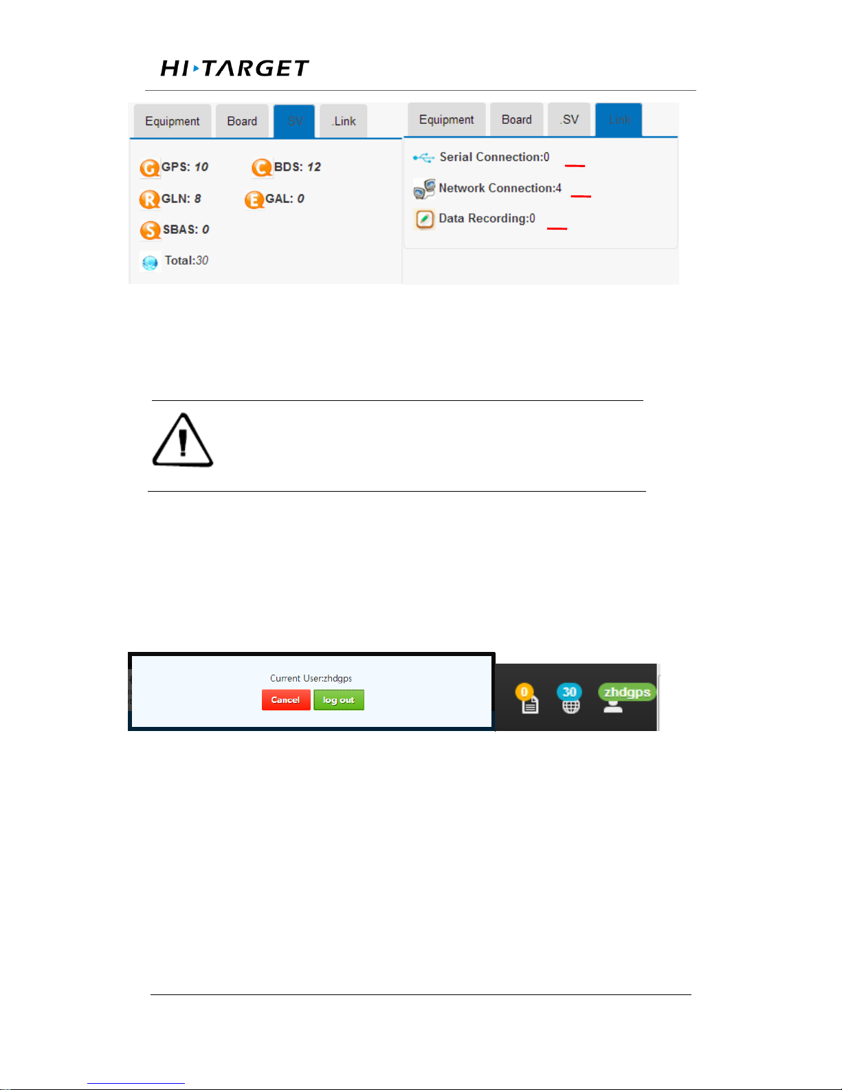
Status bar
Satellite status, login account and language setting are shown in this sector
(refer to figure 3-4).
Figure 3-4 Status bar
Satellite status: this icon shows the amount of observing satellites, click it
to show the satellite info page.
Current account: this icon shows current login information.
Language setting: change language between English and other language.
3.4 Home page
Number of opened port.
Number of running transmission
Number of enabled records.
Page 27
Surveying the world,Mapping the future.
ADD: Building13, Tian’An Technology Zone HQ center, No.555, the North of Panyu RD, Panyu District 511400, Guangzhou,
China.
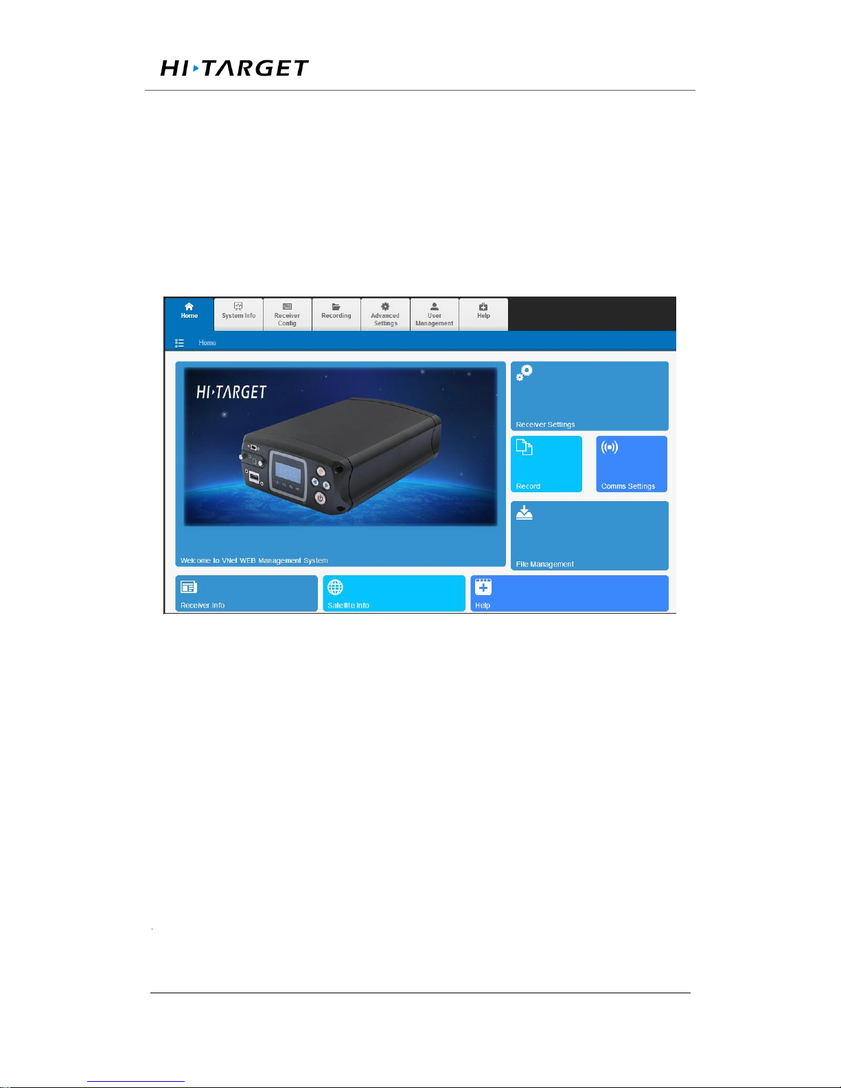
This interface is comprised of welcome page, reference station
configuration, data recording, online transmission, files downloading,
instrument info, satellite view, hyperlink option. By clicking the icon in
hyperlink option sector, users can directly reach the corresponding page for
further operation.
Figure 3-5. Main page
3.5 System info
This sector contains three modules: instrument info, satellite info and
position info for the more detailed display of GNSS receiver status and
observation.
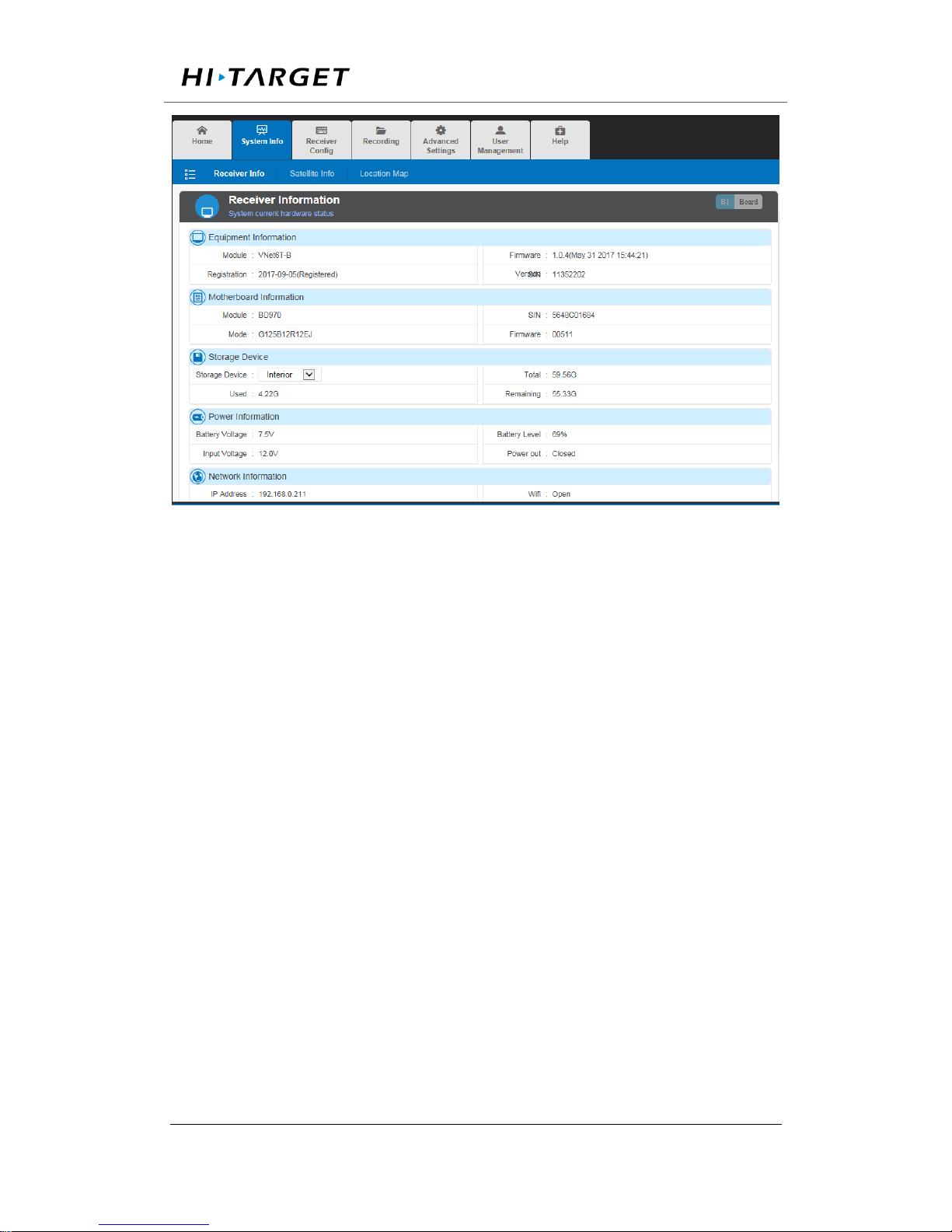
Displaying current status of system including instrument info, motherboard
info, storage device, power supply, network info as shown in figure 3-6.
Page 28
Surveying the world,Mapping the future.
ADD: Building13, Tian’An Technology Zone HQ center, No.555, the North of Panyu RD, Panyu District 511400, Guangzhou,
China.
Figure 3-6. Equipment info
In the storage device tab, different storage address (internal storage, U-disk,
TF card) could be chosen by clicking the inverted triangle on the right of
dialog. When changing the storage address, storage information will be
updated and displayed automatically.
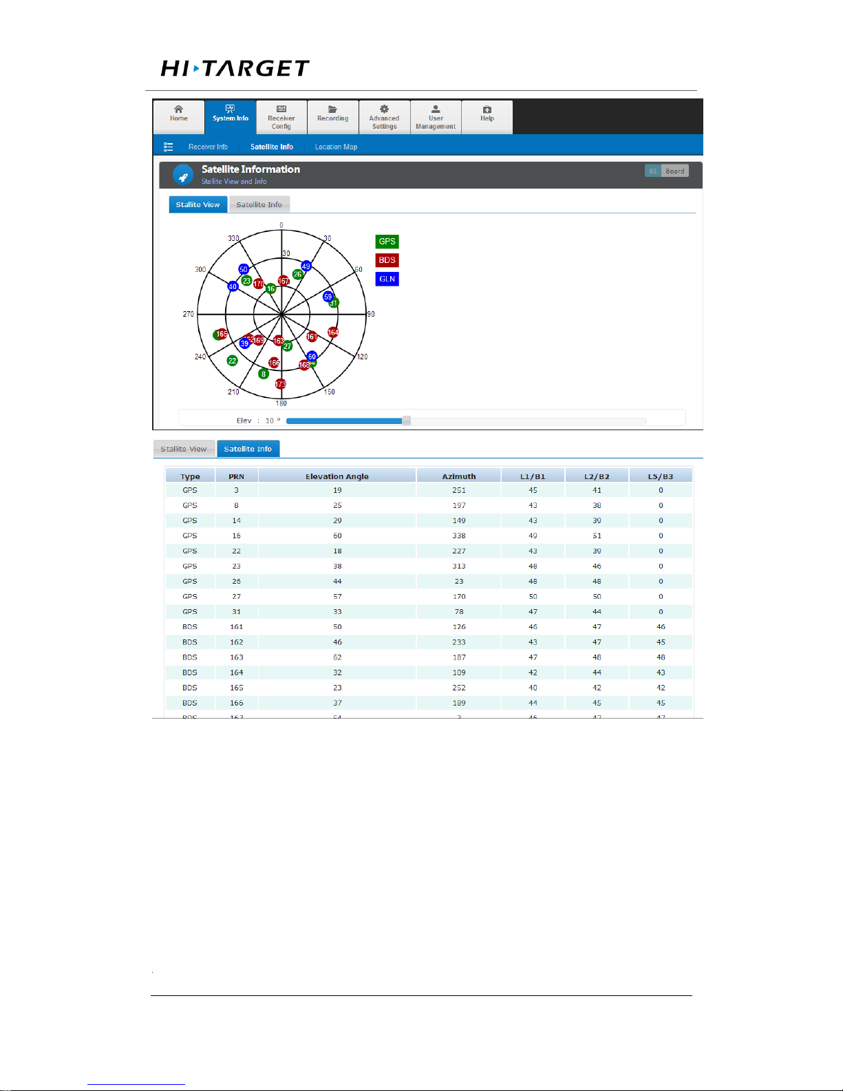
Satellite info
This sector shows the sky plot of satellites, satellite ID, altitude angle,
azimuth, signal-noise ratio (SNR), etc.
Page 29
Surveying the world,Mapping the future.
ADD: Building13, Tian’An Technology Zone HQ center, No.555, the North of Panyu RD, Panyu District 511400, Guangzhou,
China.
figure 3-7. Satellite info
Position info
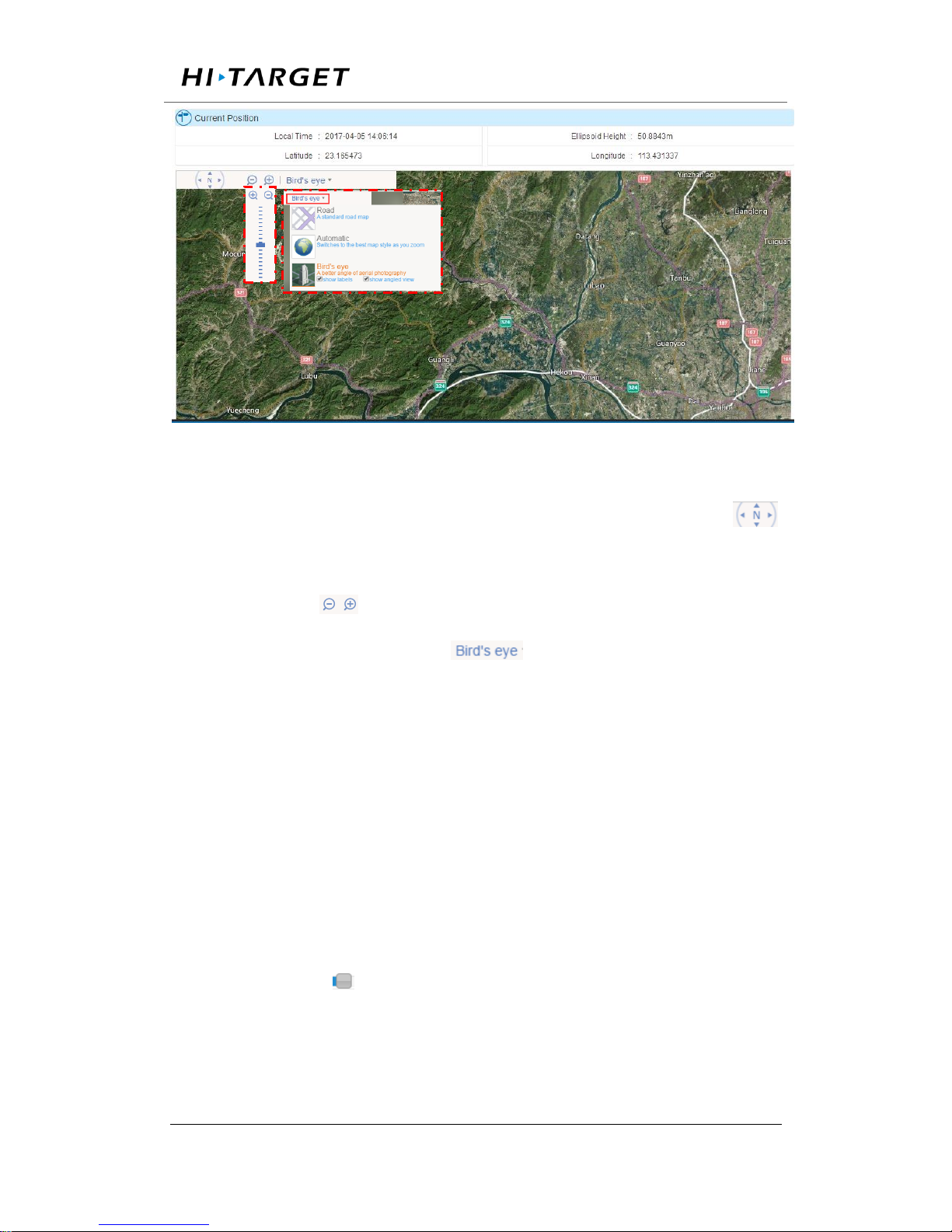
The exact location of device is shown in this sector and displayed with base
map (satellite image as default, refer to figure 3-8).
Page 30
Surveying the world,Mapping the future.
ADD: Building13, Tian’An Technology Zone HQ center, No.555, the North of Panyu RD, Panyu District 511400, Guangzhou,
China.
figure 3-8. Position info
Under the display with base map, press the arrow key (on the icon of )
to move the screen with corresponding direction. Zoom in/out with
pressing icon of . Besides, 2D digital map and satellite image are
available options in the dialog of .
3.6 working mode
This sector will introduce configuration of satellite, reference station, serial
ports as well as online transmission and data recording module.
Satellite setting
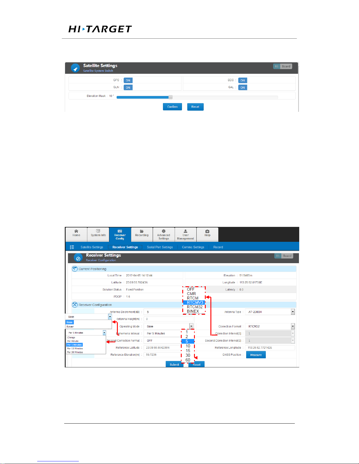
Satellite system switch on/off and cut-off angle setting: 【OFF】means
system is turn off . whereas 【ON】indicates working status is turn on.
Dragging the icon can change the value of cut-off angle (decreasing
with left drag and right to increase). Clicking 【OK】to confirm parameter
setting and reset to default by 【reset】. The interface was shown as figure
Page 31
Surveying the world,Mapping the future.
ADD: Building13, Tian’An Technology Zone HQ center, No.555, the North of Panyu RD, Panyu District 511400, Guangzhou,
China.
3-9 below.
figure 3-9. Satellite setting
Receiver setting
This sector will display the positioning status, antenna parameters and
working mode. The local time, latitude/longitude, elevation, HDOP, PDOP,
VDOP are displayed in present positioning status and reference station
configuration is categorized into antenna setting and working mode setting.
figure 3-10. Reference station setting
Antenna model, height and antenna decrement could be configured in
Page 32

Surveying the world,Mapping the future.
ADD: Building13, Tian’An Technology Zone HQ center, No.555, the North of Panyu RD, Panyu District 511400, Guangzhou,
China.
‘Antenna setting’.
Antenna decrement:the value could be set in the range of 5dB to 20dB
according to the motherboard model and antenna model. Here is the
calculating formula below:
Antenna decrement = antenna gain- motherboard gain- cable gain
Antenna model: in base station mode, choosing right antenna model to
calibrate the phase center position.
Antenna height: in base station mode, input the height to calibrate
measured elevation value.
Receiver could be set as base station or rover station. other settings in terms
of data recording, GNSS data output via serial port, network transmitted
data are various as the different mode setting.
Table 3.2 reference station setting and data output
Working
mode
Second
correction
Time tab
Raw data option
Correction option
Base
off
off
Output raw data
Output correction
on
off
Output correction
Output correction
off
on
Output raw data
Output time tab
on
on
Output correction
Output time tab
Rover
-
off
Output raw data
Output GGA data
-
on
Output raw data
Output time tab
Base station
Page 33
Surveying the world,Mapping the future.
ADD: Building13, Tian’An Technology Zone HQ center, No.555, the North of Panyu RD, Panyu District 511400, Guangzhou,
China.
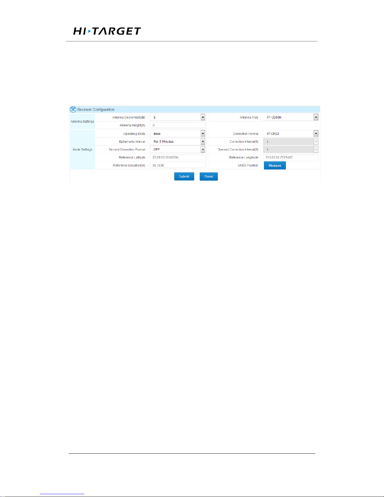
Base station setting contains correction data format, correction interval,
ephemeris output interval, 2nd correction output and station coordinates
setting & auto-acquire.
Figure 3-11 Base station setting
Ephemeris interval:setting interval as 1min, 5mins, 15mins or 30mins.
Correction data format/2nd correction output : setting as OFF ( no
correction data output),CMR,RTCM(RTCM2.3),RTCMV3(RTCM3.0),
RTCM32(RTCM3.2).
Coordinates input manually:following the format DD:MM:SS, second
could be set as decimals with no more than 8 decimal places.
Coordinates auto-acquire: average measure coordinates. Press 【submit】
to finish the setting.
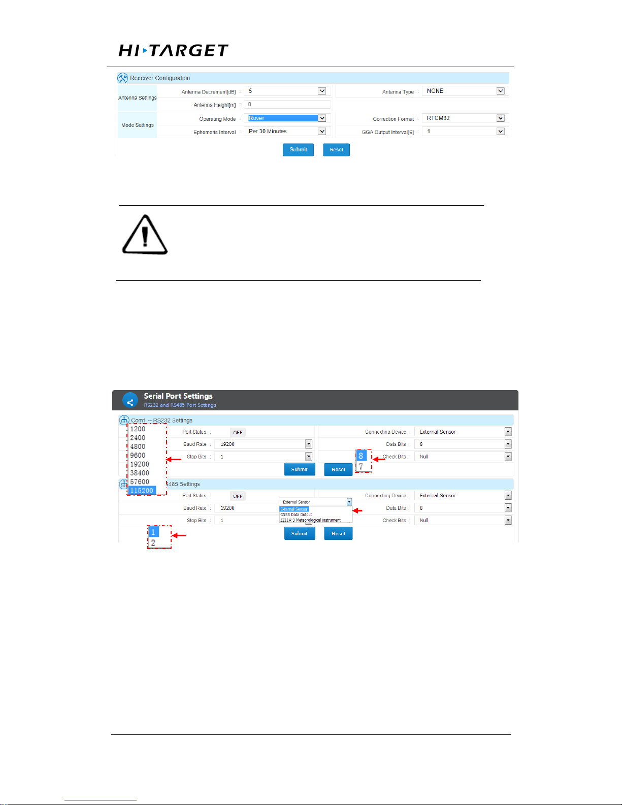
Rover Station
In rover station working mode, correction data format, ephemeris interval
and GGA output should be set. Refer to the base station setting, correction
data format, ephemeris interval is the same as the Base.GGA messages
outputs by correction message channel.
Page 34
Surveying the world,Mapping the future.
ADD: Building13, Tian’An Technology Zone HQ center, No.555, the North of Panyu RD, Panyu District 511400, Guangzhou,
China.
Figure 3-12 Rover setting
Note:1. On base station mode, set correction format as RTCM if RTD correction
is needed.
2. Raw data cannot be recorded and transmitted if turn on 2nd correction
output. The raw data displayed on the data transmission page is virtually the
2
nd
correction data.
Serial port setting
RS232 and RS485 port possess identical function that could be used for
GNSS data output and sensor data input. They two share the same setting
method e.g. Serial port Baud rate, Data bits, stop bits, check bits, etc.
Figure 3-13. Serial port setting
The introduction below follows setting RS232 as sensor data input and
RS485 as GNSS data output.
External sensor: setting 【serial port status】 as 【ON】. In 【equipment
connecting】, choose 【external sensor】. Then set baud rate, data bits,
Page 35
Surveying the world,Mapping the future.
ADD: Building13, Tian’An Technology Zone HQ center, No.555, the North of Panyu RD, Panyu District 511400, Guangzhou,
China.
stop bits and check bits according to the equipment parameters and confirm
by clicking 【submit】.
GNSS data output:setting 【port status】 as 【ON】, In 【connecting
device】, set as 【external sensor】 and choose corresponding 【data type】,
set baud rate, data bits, stop bits and check bits and confirm by clicking
【submit】.
Note:1. Make sure set right baud rate, data bits, stop bits and check bits,
otherwise, would reveal wrong message.
2. ‘Correction data’ is in connection with reference station working mode.
In base station mode, the correction data is the correction received by
receivers whereas GGA data outputted from receivers in rover mode.
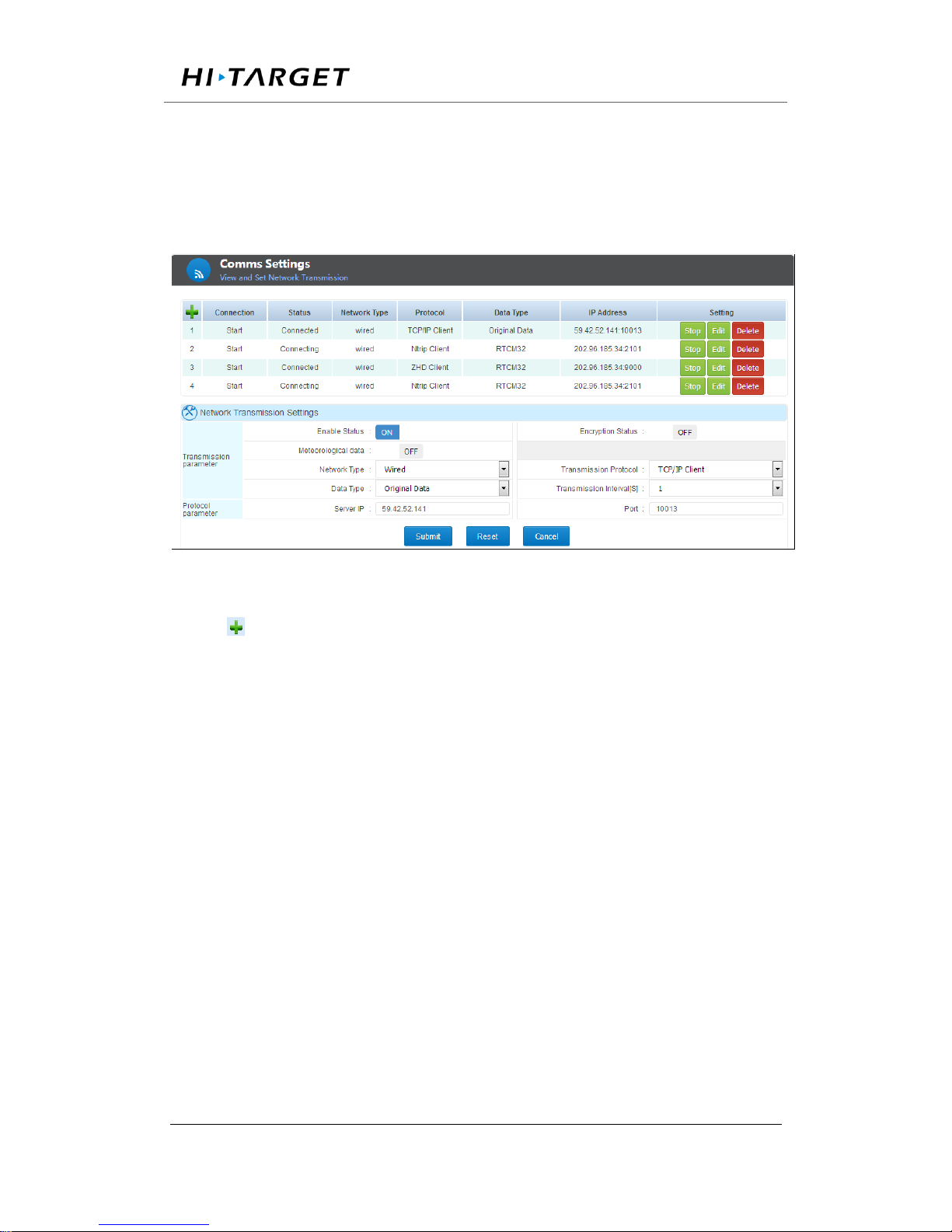
Comms transmission (Network transmission)
Transmission table consists of:
Serial number: the order code for online transmission.
Utilization: showing the status of chosen online transmission (on/off).
Status: this status contains ‘connecting’ and ‘connected’ two options.
‘connecting’ indicates this transmission is trying to connect or cannot
connect. While ‘connected’ means the transmission is connected.
Network type: consists of cable line, Wi-Fi, 2G/3G.
Protocol: the network protocol adopted, consists of Ntrip Client、TCP/IP
Client、ZHD Client、UDP Client、SG Client、Ntrip Server、TCP/IP Server
and UDP in which Server ZHD Client and SG Client are Hi-Target
protocols.
Page 36
Surveying the world,Mapping the future.
ADD: Building13, Tian’An Technology Zone HQ center, No.555, the North of Panyu RD, Panyu District 511400, Guangzhou,
China.
IP address: displaying IP and port of receiver when set as server and
displaying server’s when set as client side.
Operation: contains switch on/off, editing and deleting transmission.
figure 3-14. Comms transmission
Click button to add a online transmission. Click 【edit】to edit current
online transmission. The online transmission configuration dialogue (refer
to figure 3-14) shown when adding or editing the transmission. Refer to
the chapter 【adding online transmission】 in chapter 【basic operation】
for more details.
Encryption status: when this function is switched on, the data can be only
processed using Hi-Target software or software integrated with Hi-Target
protocol.
Relevant definitions in【Comms transmission setting】
Network Type:cable, Wi-Fi, 2G/3G are available.
Data type: NMEA-0183, correction data, raw data, RS232 data, RS485
Page 37
Surveying the world,Mapping the future.
ADD: Building13, Tian’An Technology Zone HQ center, No.555, the North of Panyu RD, Panyu District 511400, Guangzhou,
China.
data. Raw data output could set 【transmission interval】 (0.05s, 0.1s, 0.2s,
0.5s, 1s, 2s, 5s, 10s, 15s, 30s, 60s).
There are 8 protocols available with options of network setting and data
type. Detail settings as below shows.
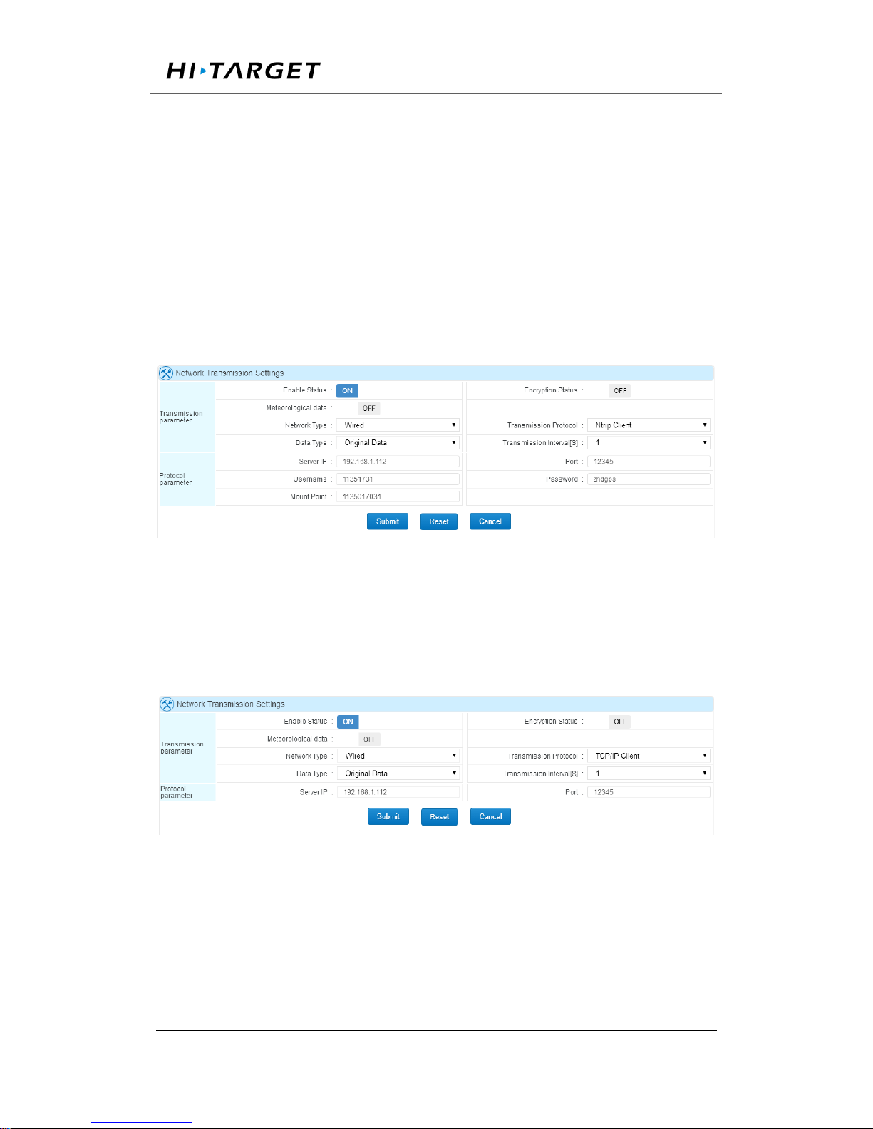
Ntrip Client, Ntrip Server share the same setting, define the parameters
according to the local network setting (refer to figure 3-15).
Figure 3-15 Ntrip Client and Ntrip Server setting
TCP/IP Client、UDP Client share the same setting, define IP address and
port (shown as figure 3-16).
Figure 3-16 TCP/IP Client and UDP Client setting
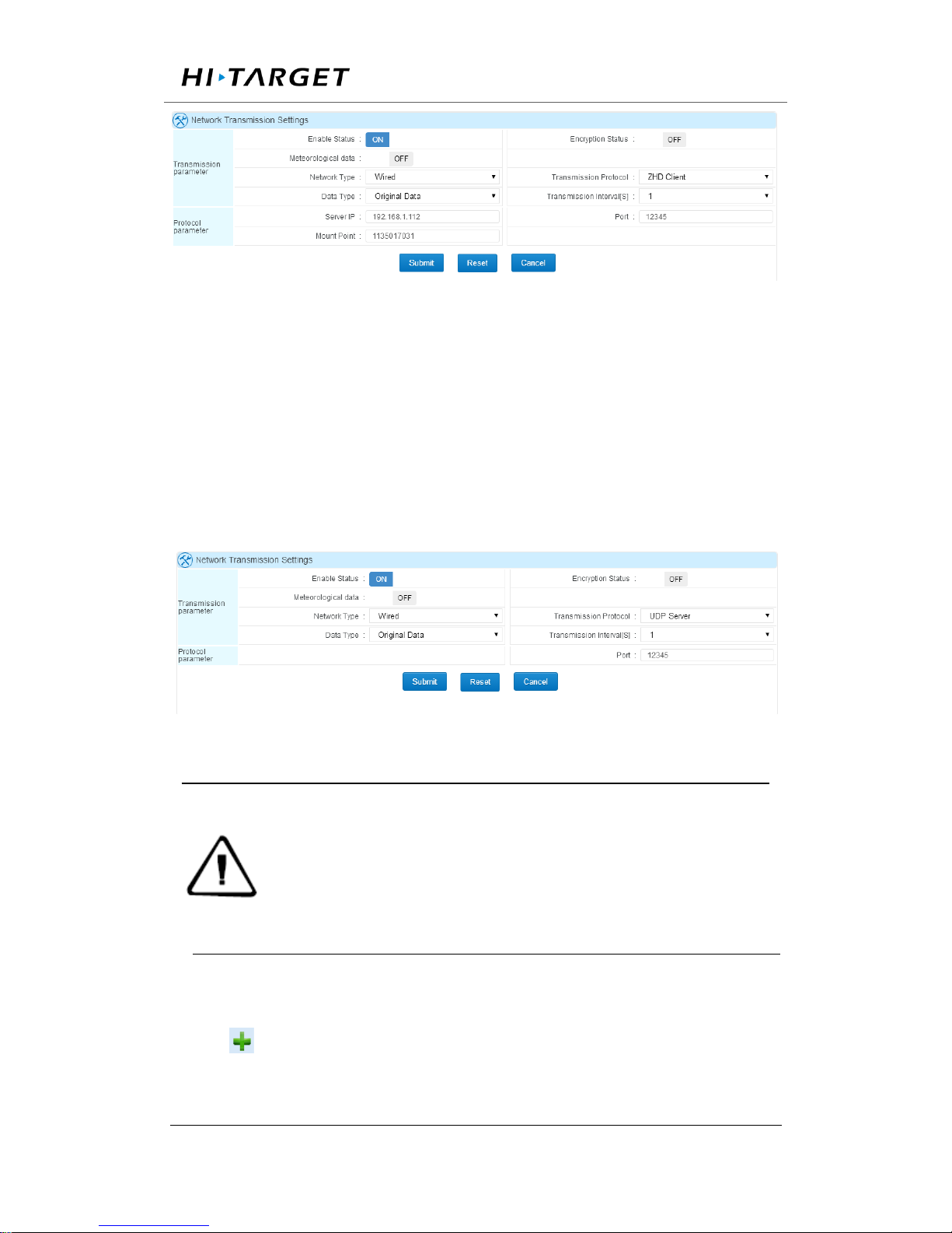
ZHD Client is Hi-Target defined transparent transport protocol, setting IP
address, port and Mount Point (refer to figure 3-17).
Page 38
Surveying the world,Mapping the future.
ADD: Building13, Tian’An Technology Zone HQ center, No.555, the North of Panyu RD, Panyu District 511400, Guangzhou,
China.
Figure 3-17 ZHD Client setting
TCP/IP Server、UDP Server transport protocol are applied with receivers
as server. Under this configuration, IP address is the one of receiver address
so that only receiver port settings are needed.
图 3-18 TCP/IP Server and UDP Server setting
Notice:1. For network transmission, different protocol cannot be set connecting
to the same server IP and port.
2. Correction data output is related to receiver working mode. In Base mode,
it outputs correction message whereas GGA data would be output for Rover
mode.
3. While transmitting data via RS232 or RS485 port, turn on the port first and
connecting ‘External Sensor’ as device.
Data logging
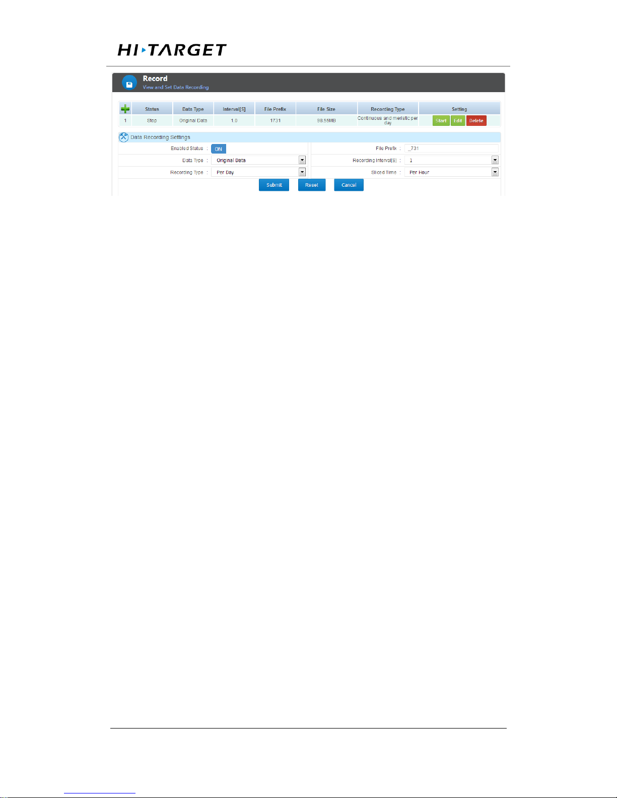
Click to add a new data record, set up the data type, recording
interval ,etc. shown as blow.
Page 39
Surveying the world,Mapping the future.
ADD: Building13, Tian’An Technology Zone HQ center, No.555, the North of Panyu RD, Panyu District 511400, Guangzhou,
China.
Figure 3-20 data logging
Enable the data record and then set the flag name (the file name of data file
header, the default setting is _zhd), select the record data type, we provide
the original data and Rinex formats. At the same time data records can be
set to a different recording interval.
Recording methods are recorded every day, manual recording and planning
time records, etc., when the daily record mode is enabled to record the file
can also choose a file every day, every hour, every two hours split a file
The Select the data record format as needed. After setting, click the [Submit]
button.
【Start】【 Stop】is for the status switch of existing transmission.
【Delete】means to erase one item from existence
3.7 File management
File management including File list and FTP push function. Users are able
to storing, checking, downloading, deleting all data files. This function is
only accessible for Normal users and Administrator.
Page 40
Surveying the world,Mapping the future.
ADD: Building13, Tian’An Technology Zone HQ center, No.555, the North of Panyu RD, Panyu District 511400, Guangzhou,
China.
File list
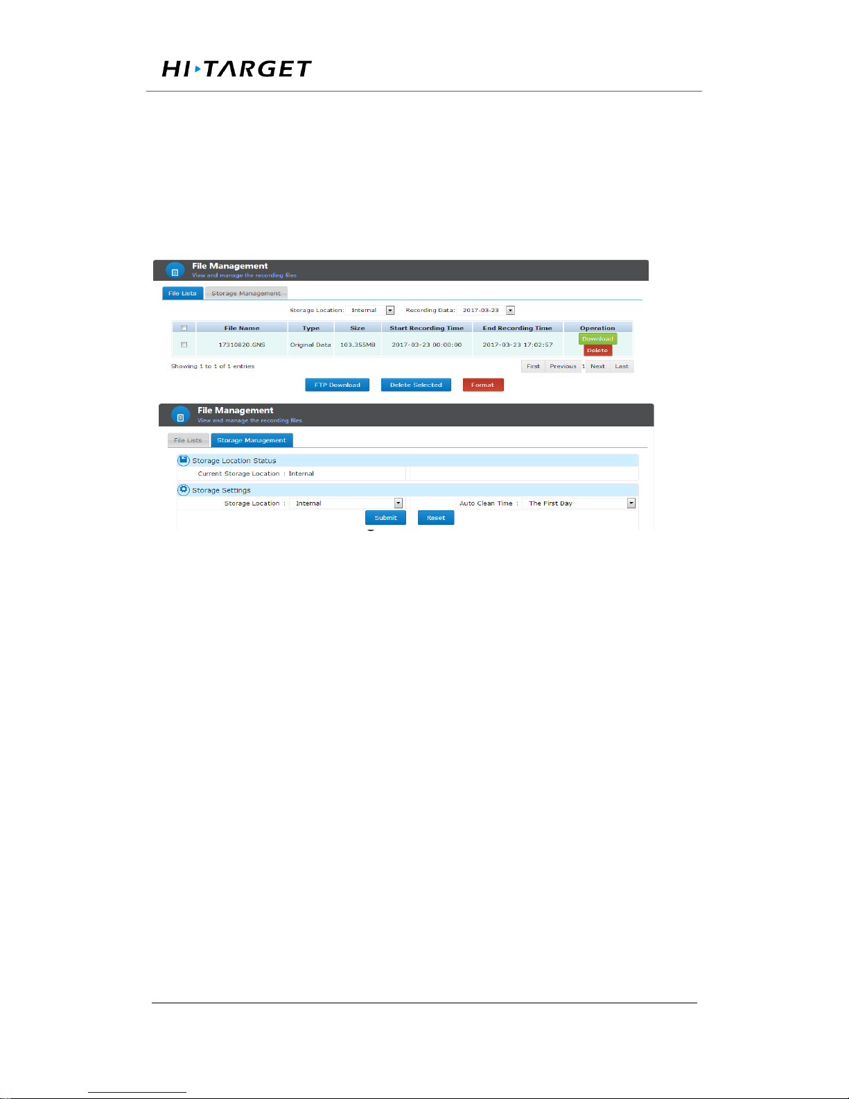
In this function, users can check and manage the recording files stored in
different device. Those files could be auto deleted via setting ‘Auto clean
time’.
Figure 3-21 File list
Stored directory could be selected internal (internal storage), U-disk and
TF card. Once the record date is chosen, the page will refresh automatically.
File name: the name of recorded data files.
Type: the data type of files, normally they are RINEX file or Original data
(RAW data) file.
Size: Disk storage space.
Start recording time: the beginning time of this recording, usually the
moment when file was created.
End recording time: the ending time of this recording, that is the moment
when this recording stop.
Operation: To download or delete this data record.
Page 41

Surveying the world,Mapping the future.
ADD: Building13, Tian’An Technology Zone HQ center, No.555, the North of Panyu RD, Panyu District 511400, Guangzhou,
China.
The downloading function of file list could be conducted by ordinary
download or FTP download. Refer to chapter ‘data downloading’ in ‘basic
operation’.
There are three ways to go for data deleting action.
Simple delete: only for deleting single file, directly clicking 【Delete】
button on the recording form.
Selective delete: when delete more than one file, select by ticking them on
the row head then click 【Delete selected】. All items could be selected
by tick the header tick box.
Format: deleting all data file.
FTP push
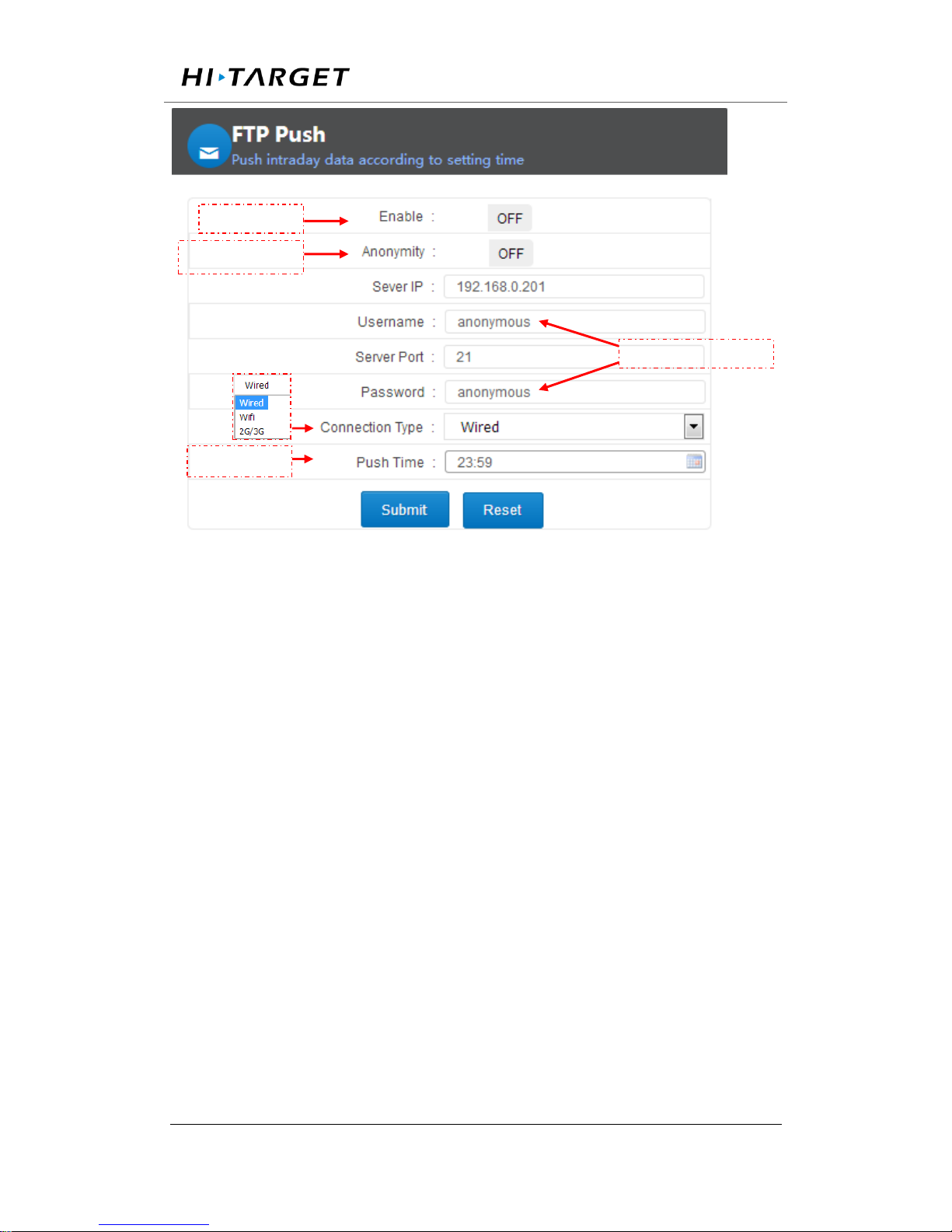
FTP push function could send the data file recorded between 00:00 and
fixed time point to the server. Detailed configuration displayed below:
Page 42
Surveying the world,Mapping the future.
ADD: Building13, Tian’An Technology Zone HQ center, No.555, the North of Panyu RD, Panyu District 511400, Guangzhou,
China.
Figure 3-22 FTP push
【Reset】button would reset the setting as factory default, click 【Submit】
to apply the setting.
3.8 Advanced setting
The Advanced page provides advanced commands and operations for the
device, including host settings, motherboard settings, network settings, and
log management viewing.
Advanced pages are only open to administrators and others are not allowed
to view.
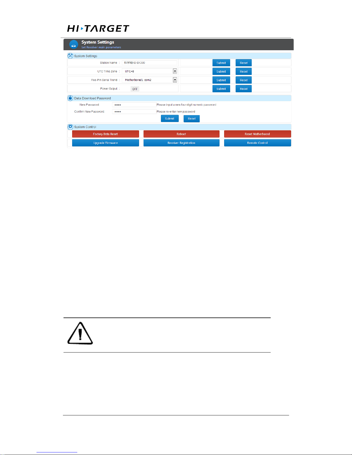
System Settings
System settings is composed of system settings, data download password
and system control.
FTP Switch
Anonymity Switch
User name/ Pass word
Time setting
Page 43
Surveying the world,Mapping the future.
ADD: Building13, Tian’An Technology Zone HQ center, No.555, the North of Panyu RD, Panyu District 511400, Guangzhou,
China.
Figure 3-23 system settings
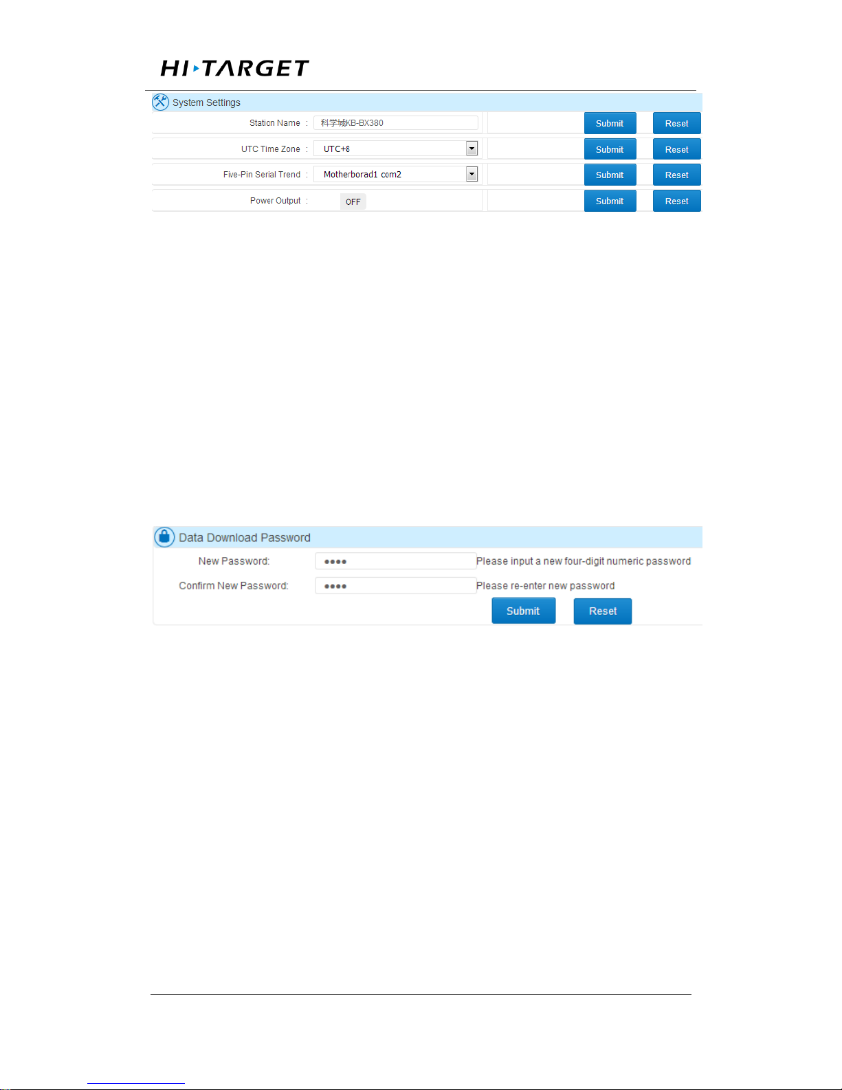
1. System settings
a. Station name settings: set the station name, the default value is "Station
A". To change it, just directly input the name and then click 【submit】
button.
b. UTC time zone: from there are 25 zones in total from UTC -12 to UTC
+ 12, the default value is UTC +8; to change it, select the right one and
click 【submit】.
c. Five-pin serial Trend: this five-pin serial port has been directly connected
with motherboard. That makes it possible to obtain data from motherboard
but limited from sending command or message to motherboard. To change
it, select the port and click 【submit】.
Note:COM1 is used for data output e.g. GGA, GSV, etc whereas correction
message/ time tag are output via COM2. As for COM3, raw data/ second
correction message output through it.
d. Power output: This function could supply power with 12VDC,5W
devices.
Page 44
Surveying the world,Mapping the future.
ADD: Building13, Tian’An Technology Zone HQ center, No.555, the North of Panyu RD, Panyu District 511400, Guangzhou,
China.
Figure 3-24 System settings
2. Data download password
The password is designed for security of local data downloading. Applying
for data file downloading within the use of LED button. This string is
composed of four digits with default setting 1234; to change it, enter the
new password and click 【submit】. Clicking 【Reset】 and 【submit】,
the password would be reset back to 1234.
Figure 3-25 Data download password
3. System control
Users can remotely control the receiver via this web page. Mainly include:
restore factory settings, restart, and reset the motherboard, upgrading
firmware, receiver registration and remote control.
Restore factory settings: Click 【Restore Factory Settings】, the dialog box
will pop up, click 【OK】; The receiver will return to the factory default
value and restart automatically. After the restart to delete all the data and
settings, see Annex [restore factory settings];
Page 45
Surveying the world,Mapping the future.
ADD: Building13, Tian’An Technology Zone HQ center, No.555, the North of Panyu RD, Panyu District 511400, Guangzhou,
China.
b. Reboot: Receiver restart, click【restart】, pop-up dialog box to select
[OK]. The receiver will restart within 10 seconds and restart for
approximately 1 minute.
c. Reset the motherboard: GNSS board will restore to the factory settings,
click [reset motherboard], and pop-up dialog box to select [OK]. After reset,
the data record re-creates the log file.
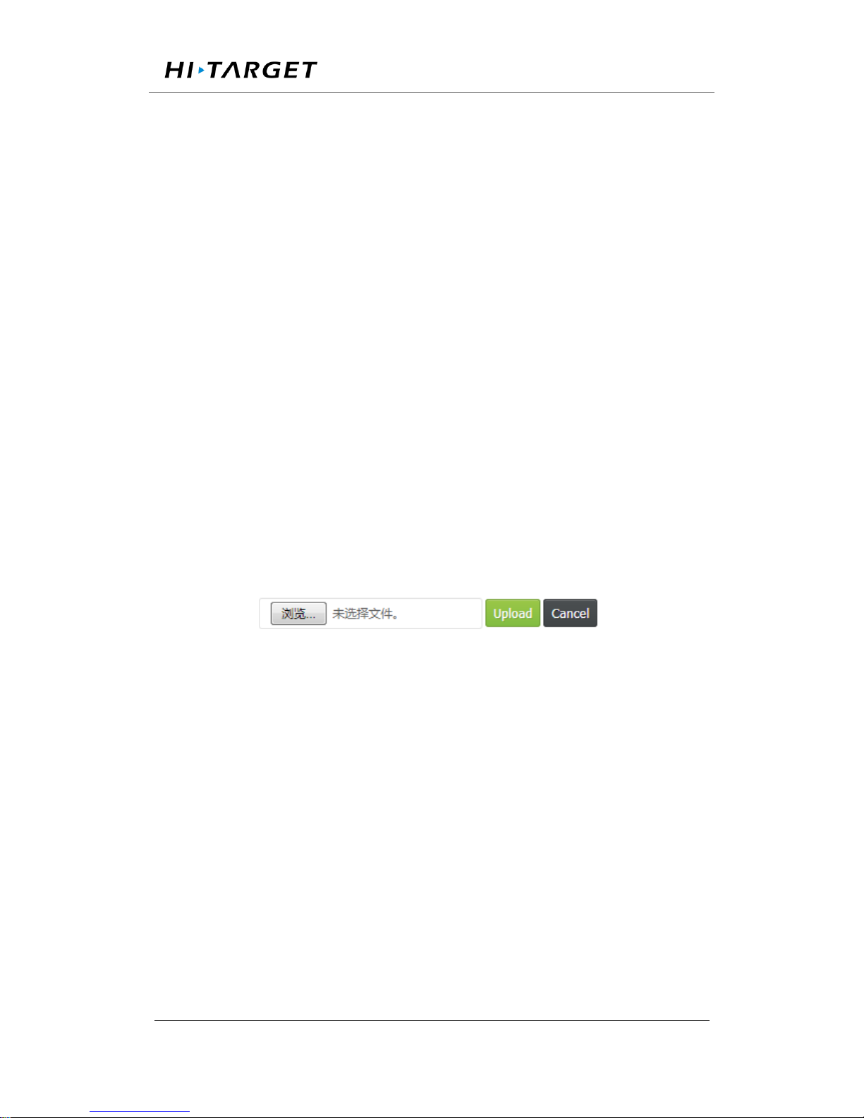
d. Upgrade the firmware: Upgrade the receiver firmware, pay attention to
its file name "VNet6Plus_Update.bin", cannot be modified. Click
【Upgrade Firmware】 to expand the following interface, click [Browse]
to select the file and click 【Upload】. For details, see 【Basic Operation】
→【Firmware Upgrade】.
Figure 3-26 Upgrading the firmware
e. Receiver registration: Input the code and submit. Receiver Registration
Detail Operation See 【 Basic Operation 】 Chapter 【 Registration
Receiver】.
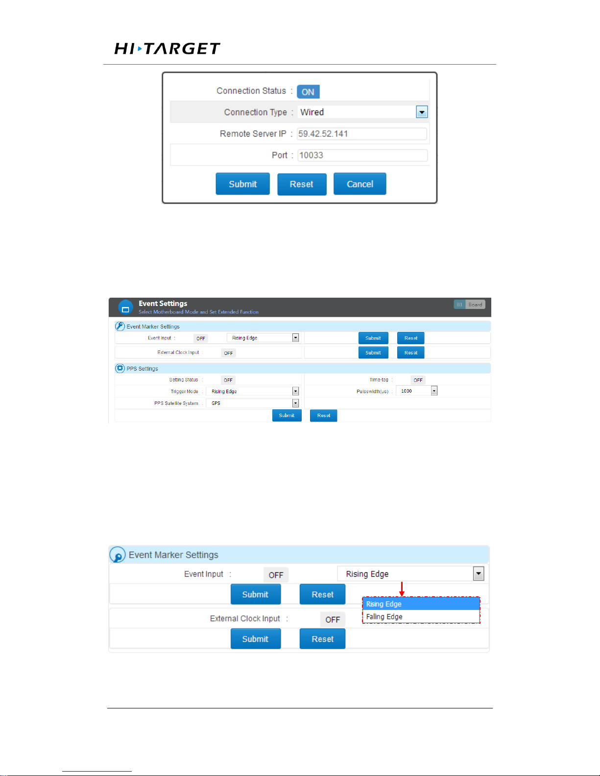
f. Remote control: Click [Remote control] and the interface display shown
as below.
Page 46
Surveying the world,Mapping the future.
ADD: Building13, Tian’An Technology Zone HQ center, No.555, the North of Panyu RD, Panyu District 511400, Guangzhou,
China.
Figure 3-27 Remote control
Event settings
This sector will introduce Event marker setting and PPS setting.
Figure 3-28. Event settings
External Clock input: to input the external clock, please make sure
you have get device connected then switch on and click 【Submit】.
Contrarily, the switch should to be off before disconnecting the
hardware.
Figure 3-30 Event Marker Setting
Page 47
Surveying the world,Mapping the future.
ADD: Building13, Tian’An Technology Zone HQ center, No.555, the North of Panyu RD, Panyu District 511400, Guangzhou,
China.
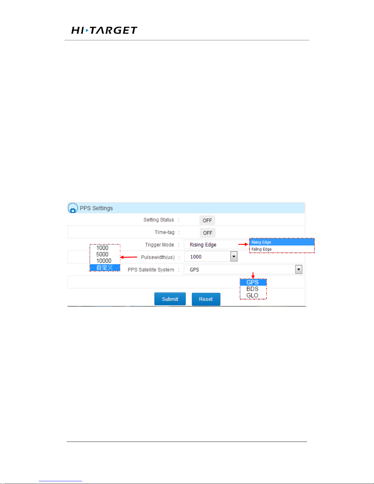
PPS setting: the output frequency is per second. This tab is capable of
setting PPS switch on/off, trigger mode (Rising Edge or Falling Edge), PPS
Satellite System (GPS, BDS, GLONASS), Time-tag, Pulse width.
When turning on the time-tag, this data will be output as correction
message. If you prefer get that info from five-pin serial port, the 【Five-
pin serial trend】 should be set as COM2. Pulse width is optional among
1000us, 5000us and 10000us. Users can also customize the value with the
range of 1000 to 500000us.
Figure 3-31 PPS setting
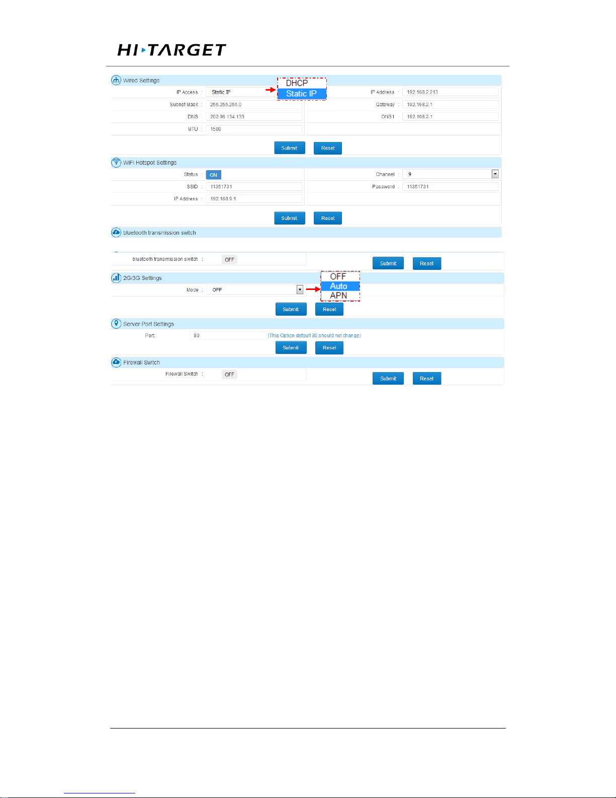
Network Status and Setting
Network setting consists of Wired setting, WiFi Hotspot setting, 2G/3G
setting, server port setting and Firewall switch.
Page 48
Surveying the world,Mapping the future.
ADD: Building13, Tian’An Technology Zone HQ center, No.555, the North of Panyu RD, Panyu District 511400, Guangzhou,
China.
Figure 3-32 Network Status and Setting
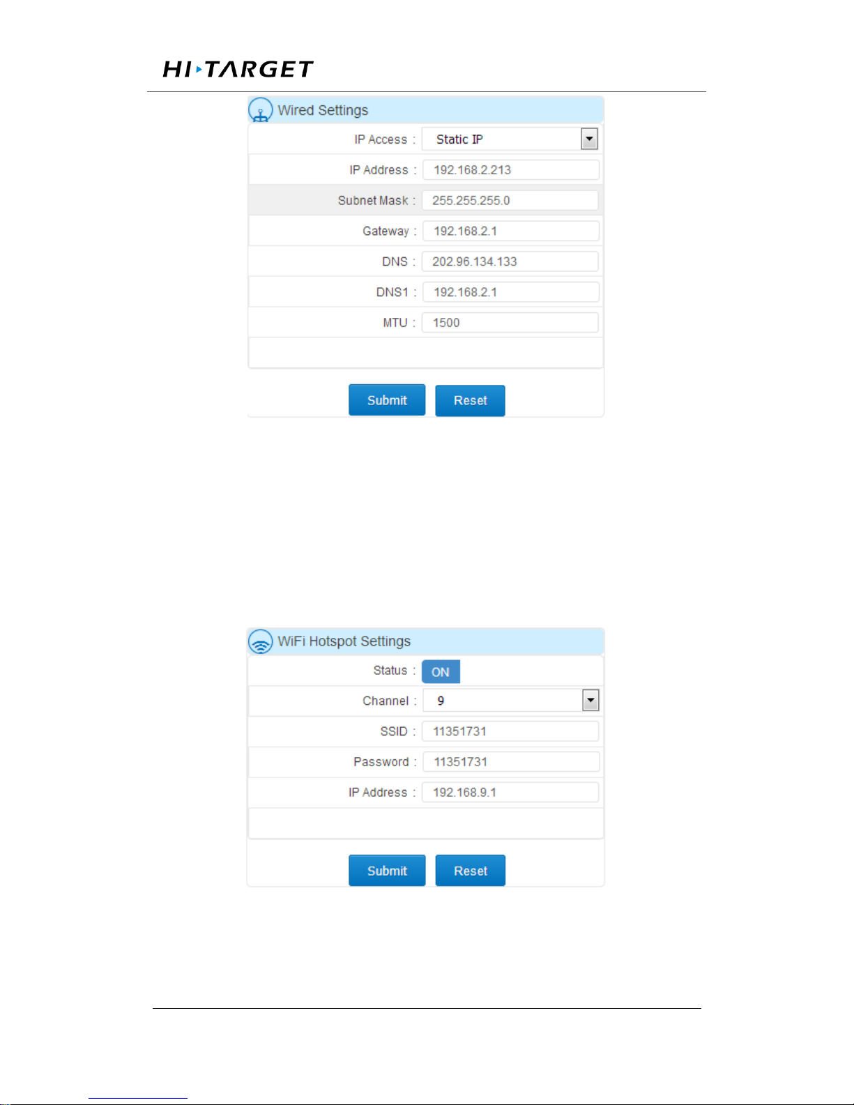
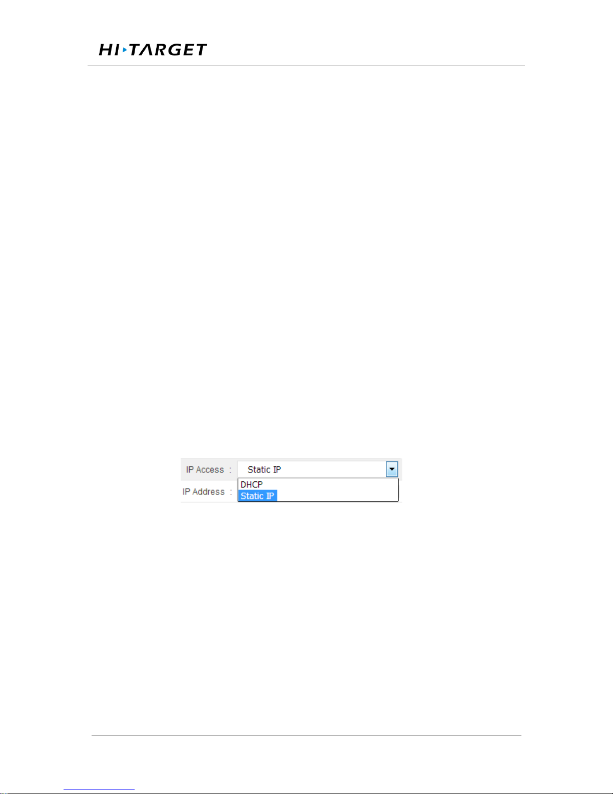
Wired setting: There are two ways to obtain IP address via wired
connection, DHCP (automatic detecting) and static IP (set manually). The
machine will automatically set all parameters under DHCP mode while all
parameters have to be set manually in Static IP. Such as IP address, subnet
mask, Gateway, DNS, etc. The configuration page is shown as figure 3-33.
Page 49
Surveying the world,Mapping the future.
ADD: Building13, Tian’An Technology Zone HQ center, No.555, the North of Panyu RD, Panyu District 511400, Guangzhou,
China.
Figure 3-33 Wired settings
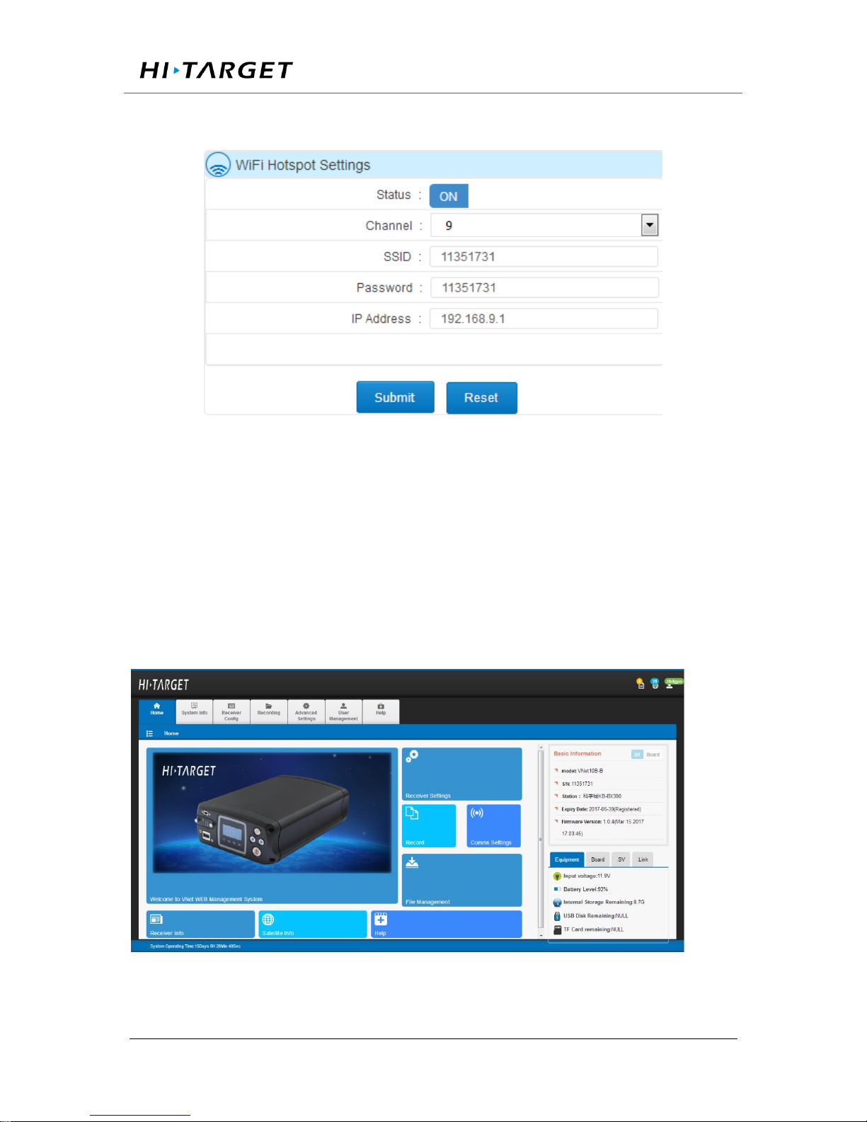
Wi-Fi Hotspot Setting: several parameters could be configured in this tab
including channel, password, IP address of receiver. The default setting for
SSID and Password are SN and ‘192.168.9.1’. Users are able to visit Web
administration page after connecting Wi-Fi.
Figure 3-34 Wi-Fi Hotspot Setting
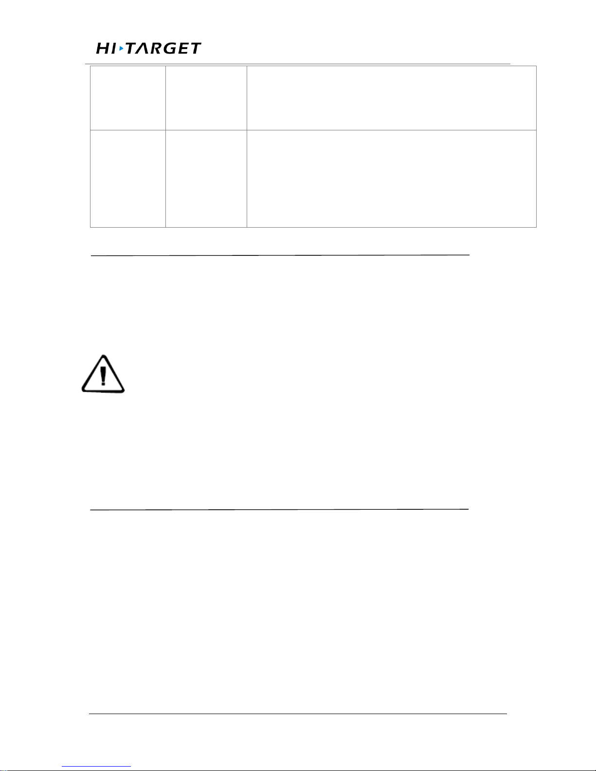
2G/3G setting: this tab is about switch on/off 2G/3G function and settings
(APN or Auto mode). Access point, Username and Password must be input
Page 50

Surveying the world,Mapping the future.
ADD: Building13, Tian’An Technology Zone HQ center, No.555, the North of Panyu RD, Panyu District 511400, Guangzhou,
China.
manually in APN mode whereas everything could be set automatically
under Auto mode.
Figure 3-35 2G/3G Setting
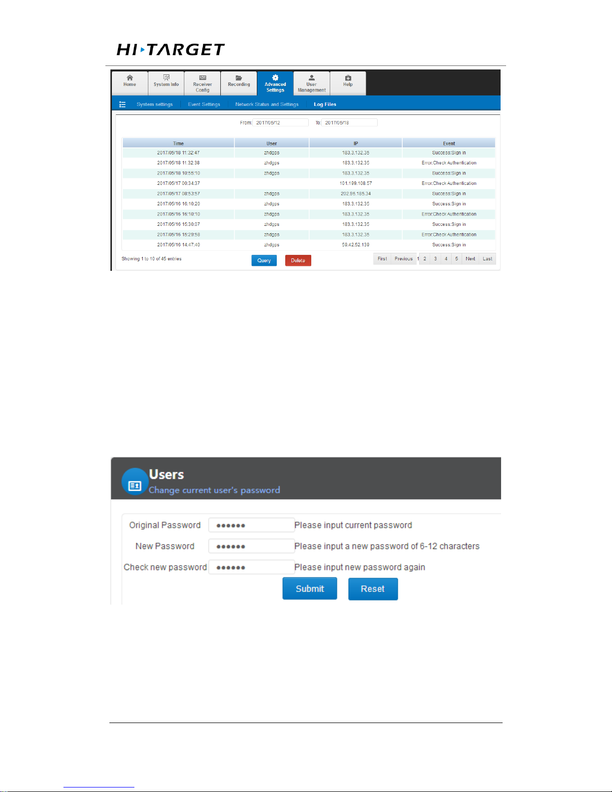
Log Files
System log files records all user operation logging file during the running
period and they list following time sequence. The content mainly contains
users logging in, page switching, setting changing, data file downloading,
transmitting, deleting. As well as the network setting, restart and FW
upgrading, etc.
On the log files page, setting time zone above the table to inspect all the
log files generated during this time zone. 【Delete】 button is used to delete
all the files shown on the form.
Fields on the list:
1. Time: the time point of record under 24-hour system.
2. User: the logged user of corresponding operation.
3. IP: the IP address of recorded user.
4. Event: recorded event.
Page 51
Surveying the world,Mapping the future.
ADD: Building13, Tian’An Technology Zone HQ center, No.555, the North of Panyu RD, Panyu District 511400, Guangzhou,
China.
Figure 3-36 Log files
3.9 User management
This page is composed of Users and Admin.
Users
Changing current user’s password.
Figure 3-37 Users
Admin
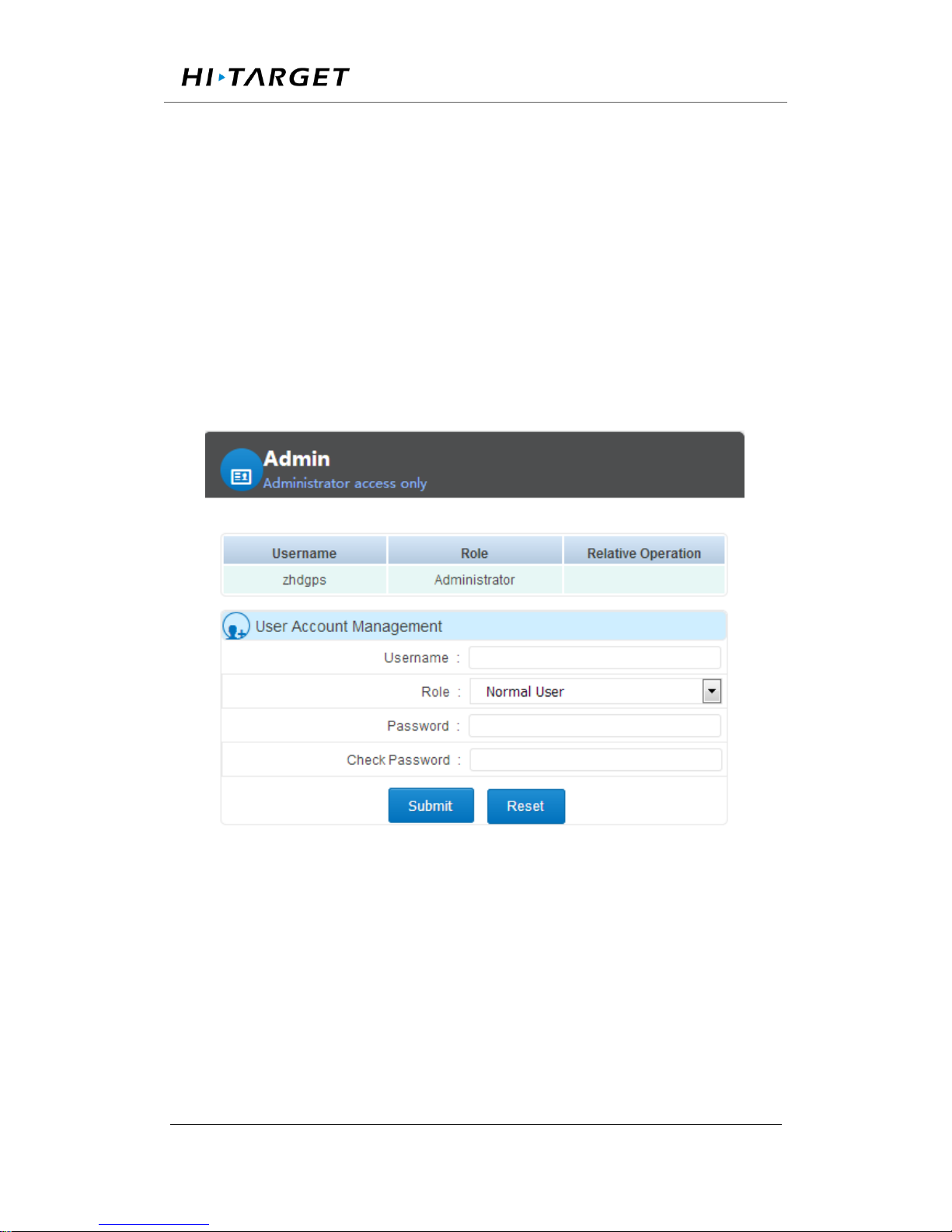
This tab is authorized to administrator (zhdgps) only and being allowed to
Page 52
Surveying the world,Mapping the future.
ADD: Building13, Tian’An Technology Zone HQ center, No.555, the North of Panyu RD, Panyu District 511400, Guangzhou,
China.
add/delete normal users only. Refer to chapter【User log in】 for more
details.
Adding new user: define user name and password on the User Account
Management tab (user name muse be composed of numbers, letters and
underline, starts with letters with the length of 5~16 digits. The password
must be 6~12 digits long). Clicking【Submit】 to finish the creating.
Deleting user: Deleting account by clicking 【Delete】button.
Page 53
Surveying the world,Mapping the future.
ADD: Building13, Tian’An Technology Zone HQ center, No.555, the North of Panyu RD, Panyu District 511400, Guangzhou, China.
Chapter 4 Basic operations
4.1 Architecture model
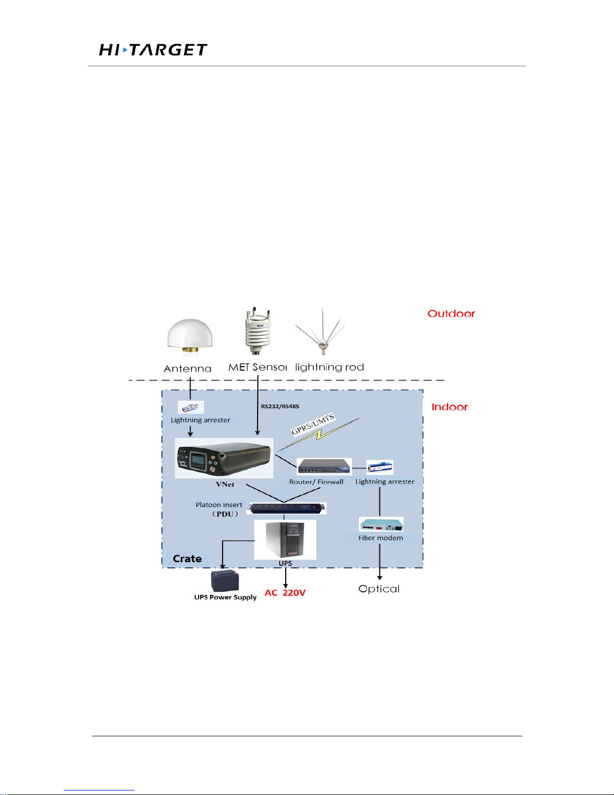
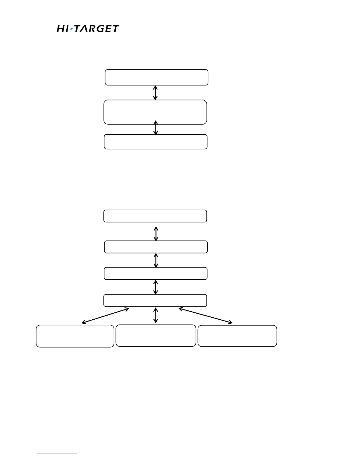
GNSS receiver products can be used for ground enhancement systems and CORS
and other fields. Receiver can connect to weather sensor and other sensors, and
connect to central service area through the network cable or 3G / 2G network. Its
architecture is generally shown in Figure 4-1:
Figure 4-1. Architecture model
4.2 Basic composition and connection
Page 54
Surveying the world,Mapping the future.
ADD: Building13, Tian’An Technology Zone HQ center, No.555, the North of Panyu RD, Panyu District 511400, Guangzhou, China.
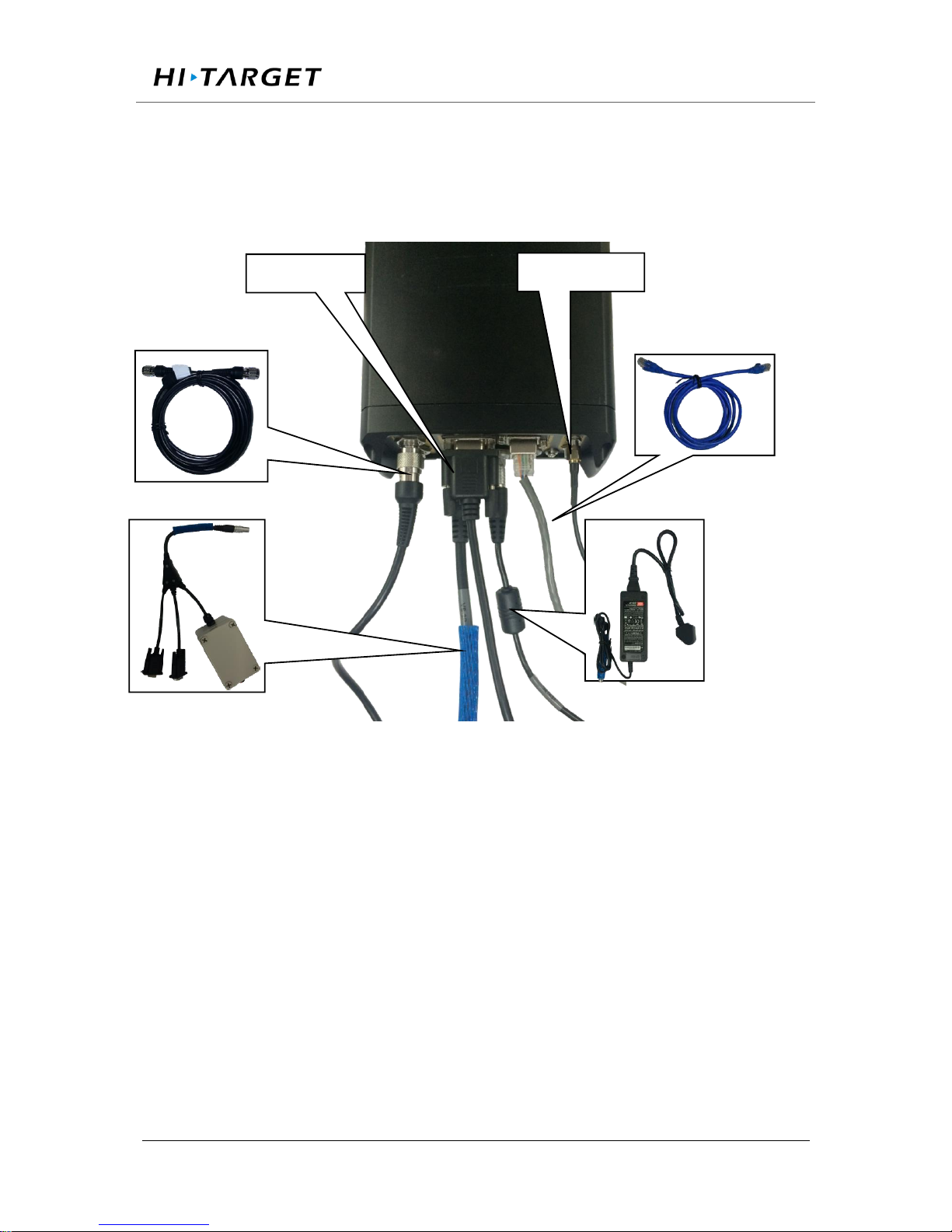
The kit includes: GNSS receiver, VNet data cable (VS-3P), 3G / 2G antenna,
GNSS antenna cable, power adapter (CL-1233), cable. The connection is shown
in Figure 4-2
Figure 4-2 Receiver connection
4.3 Connector installation
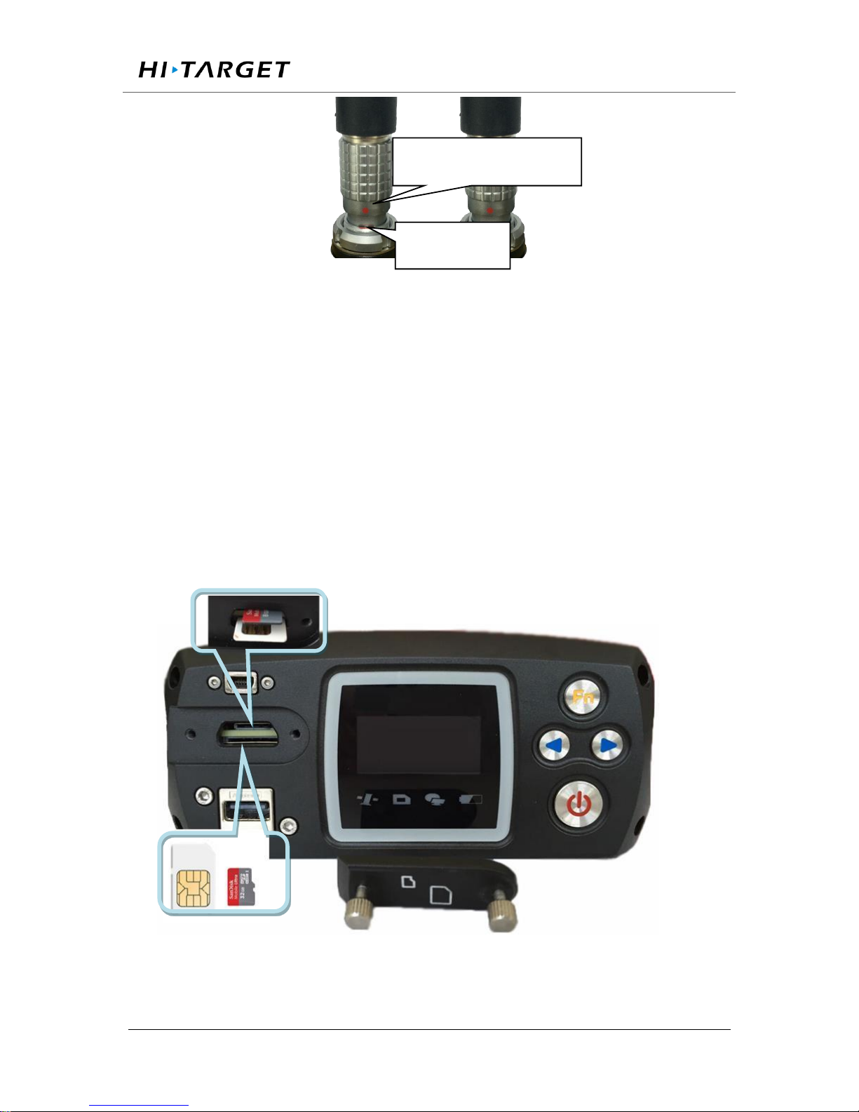
The GNSS receiver have three self-locking socket, respectively, five-pin socket,
external expansion socket, power input socket; shown as below, ensure the red dot
on cable connector is aligned with the red dot on receiver socket, or cause damage
to the receiver and cable connector; Figure 4-3:
GNSS Antenna cable
Cable
Power Adapter
VS-3P cable
2G/3G antenna
DB9 port
Page 55
Surveying the world,Mapping the future.
ADD: Building13, Tian’An Technology Zone HQ center, No.555, the North of Panyu RD, Panyu District 511400, Guangzhou, China.
Figure 4-3 Connector installation
Install, take SIM / TF card
1. Under the front panel is SIM / TF card installation slot, clockwise tighten the
screws, counterclockwise to loosen the screws.
2. Install SIM / TF card: SIM card chip is in the up layer, TF card chip is in the
second layer, oblique angle inward directly into; when you hear a sound,
installation finished.
3. take SIM / TF card: push the card, then the card pops up;
Figure 4-4 Installation / taking SIM / TF card
Red dot on connector
Socket
Page 56
Surveying the world,Mapping the future.
ADD: Building13, Tian’An Technology Zone HQ center, No.555, the North of Panyu RD, Panyu District 511400, Guangzhou, China.
4.4 Network connection
1.LAN network connection
You can use the cable to connect the GNSS receiver with the LAN, input GNSS
receiver wired network IP address (default: 192.168.0.200) in the browser, then
enter the VNet series Web management system login interface.
Notice: GNSS receiver default wired local IP is 192.168.0.200. If
the local area network segment is 192.168.0. ×, and the LAN does
not use 192.168.0.200IP, the GNSS receiver can be directly
connected to the LAN, LAN access through the IP 192.168.0.200 login; if the
local network segment is not 192.168.0. ×, such as LAN network segment
192.168.1. × or other (that is, GNSS receiver IP different from network segment),
you must add the network which segment is 192.168.0.x.
At present, often use optical fiber or ADSL to connect the network. Optical fiber
is usually with a fixed IP, and ADSL is usually a dynamic IP. Please refer to the
local telecommunications department for specific charges for optical fiber or
ADSL Internet access.
GNSS receiver and INTERNET can be directly accessed, you can also map
through the LAN external network IP to access.
Directly access method is relatively simple, in the local connection under the
Internet protocol, click 【Advanced】, in the pop-up interface, input the IP address
and gateway into WAN IP and gateway, as shown in Figure 4-5 below.
Page 57
Surveying the world,Mapping the future.
ADD: Building13, Tian’An Technology Zone HQ center, No.555, the North of Panyu RD, Panyu District 511400, Guangzhou, China.
Figure 4-5 Line connection method
The GNSS receiver base station connects to the network by mapping the external
network IP. As shown in Figure 4-6:
Figure 4-6 Mapping to the external network connection
1.Change the IP of the GNSS receiver
WAN IP:202.96.185.34
Fiber optic transponders or ADSL
MODEN
GNSS receiver IP address:202.96.185.34
WAN IP:202.96.185.34
Fiber optic transponders or ADSL
Router IP:192.168.1.1
Switch
GNSS receiver IPaddress :
192.168.168.1.200
Other computer's IP address:
192.168.1.101
Other computer's IP address:
192.168.1.102
Page 58
Surveying the world,Mapping the future.
ADD: Building13, Tian’An Technology Zone HQ center, No.555, the North of Panyu RD, Panyu District 511400, Guangzhou, China.
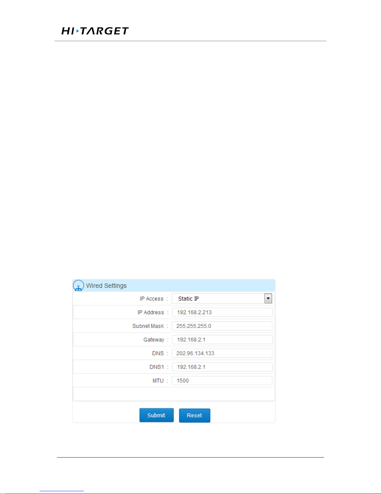
There are two ways to change the IP address of a GNSS receiver: Manual settings
and match automatically acquire settings;
A. Manual settings
Firstly, obtain GNSS receiver's local IP, such as the default value is 192.168.0.200
(if you do not know the receiver's IP, double-click the "power button" to open the
LCD, then see the receiver IP address). Use a network cable to connect PC and
GNSS receiver, set PC IP and GNSS receiver IP in the same network segment,
but different IP; such as 192.168.0.148, then the PC login and access the GNSS
receiver WEB management system using IP 192.168 .0.200, at the 【Advanced
Settings】- 【Network Settings】 -【Cable Settings】, set the GNSS receiver's
IP address, subnet mask, gateway, DNS (DNS no need to set), and Click 【submit】;
as shown in Figure 4-7:
Figure 4-7 Set the IP address settings manually
Page 59
Surveying the world,Mapping the future.
ADD: Building13, Tian’An Technology Zone HQ center, No.555, the North of Panyu RD, Panyu District 511400, Guangzhou, China.
B. Match automatically acquire settings
Double-click the "power button" to open the LCD, click the "Fn button" to enter
the menu options, click "right" select【network settings】, click the "power button"
to enter and select【wired network】, click the "power button" to set the Receiver
wired network mode changed as【DHCP】The system will automatically obtain
the IP and wired network-related parameters; then press the "Fn button" to return
to the status display main interface, check the IP, and record it; Then the PC can
access the GNSS receiver web management system through the automatically
obtained IP address. Go to【Advanced Settings】-【Network Settings】- 【Cable
Settings, 【IP Acquisition Mode】select【Static IP】, and set the receiver IP address,
subnet mask, gateway, DNS (DNS no need to set), and click【submit】; Figure
4-8:
Figure 4-8 Automatically obtain the IP address settings
2. Mapping the external network IP
Open the page and enter the address: http: //192.168.1.1 (default IP address) pop
up following dialog box (if you can’t enter the login interface, please consult
network administrator).
Enter the user name and password, the general TP-LINK initial default user name:
admin, password: admin.
Page 60
Surveying the world,Mapping the future.
ADD: Building13, Tian’An Technology Zone HQ center, No.555, the North of Panyu RD, Panyu District 511400, Guangzhou, China.
Set the local LAN LAN port, and set the IP address as the GNSS receiver IP
address.
Wi-Fi network
Wi-Fi network can be operated by LCD with button operation and WEB
management system, WEB management system also can set the Wi-Fi network
password, channel and login IP address;
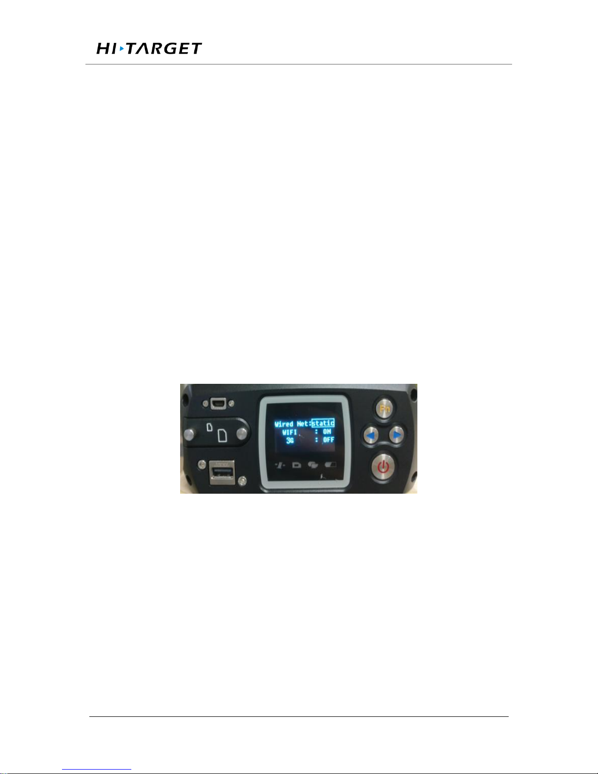
A. LCD display and key operation: double-click the "power button" to open the
LCD display, click the "Fn button" to enter the menu options, click the "right
button" to select【network settings】, click the "power button" to enter and select
【WIFI】, Click the "power button" to control the Wi-Fi network switch; as shown
in Figure 4-9:
Figure 4-9 LCD button operation Wi-Fi network on / off
B.WEB management system: log in WEB management system, set the【Advanced
Settings】-【Network Settings】-【Wifi hot set】; shown in Figure 4-10:
Page 61
Surveying the world,Mapping the future.
ADD: Building13, Tian’An Technology Zone HQ center, No.555, the North of Panyu RD, Panyu District 511400, Guangzhou, China.
Figure 4-10 Web management system Wi-Fi settings
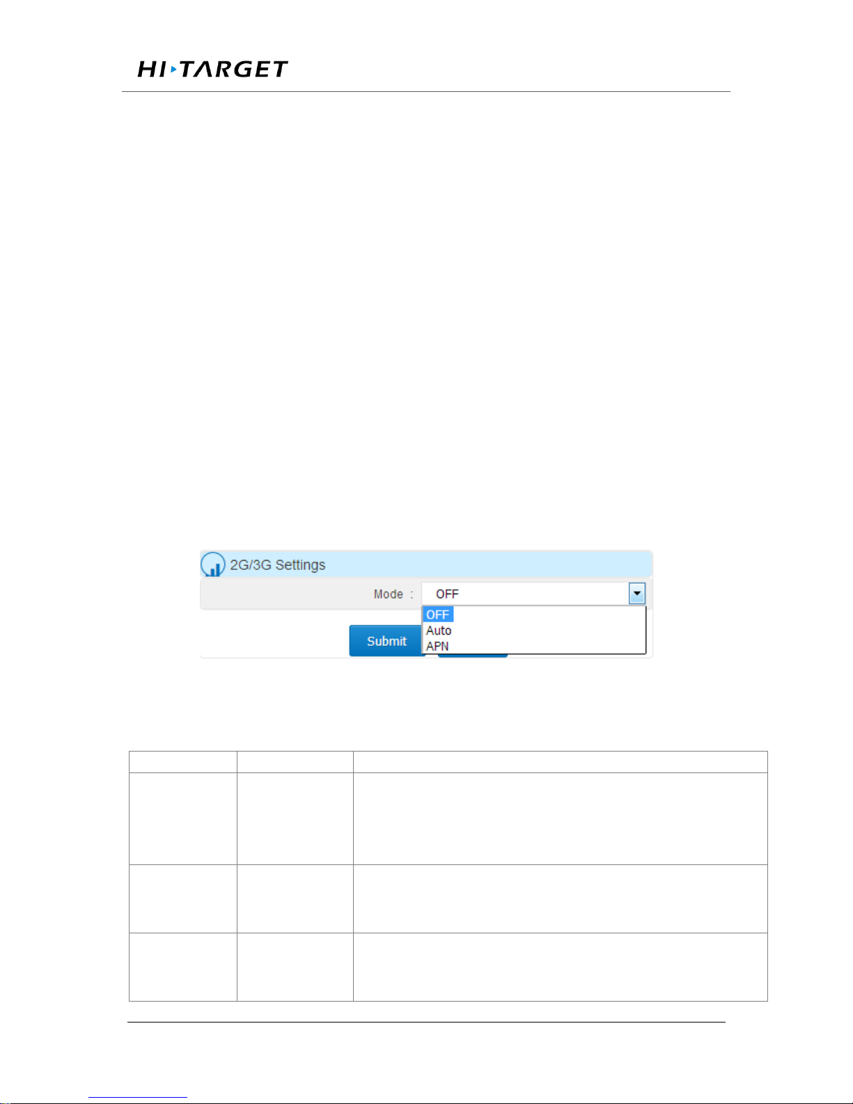
After opening VNet's Wi-Fi hotspot, users can use mobile device to search the
Wi-Fi account then enter the password (default: SN number). And then enter the
IP address of the GNSS receiver (default: 192.168.9.1) The mobile terminal
interface after logging in is shown in Figure 4-11 (Account and password same
with the PC side)
Figure 4-11 Mobile device home page interface
Page 62
Surveying the world,Mapping the future.
ADD: Building13, Tian’An Technology Zone HQ center, No.555, the North of Panyu RD, Panyu District 511400, Guangzhou, China.
2G / 3G network
FTP push, remote control and network transmission using 2G / 3G network, you
need to connect the 3G antenna, install the SIM card, under the【Advanced
Settings】-【Network Settings】, open 2G / 3G network.
If using Non-APN (green line) phone card, select【2G / 3G settings】-【Auto】
and submit, the system will automatically dial and connect;
APN line card, the users need to obtain the access point, user name and password
from the network operator, and select 【APN】 mode to fill in the access point,
user name and password (as shown below), click 【 submit】, system Will
automatically load the data and connect the data; shown in Figure 4-12:
Figure 4-12 2G / 3G network settings
4.5 LCD and button operation
Table 4-1 LCD and button operation
Function
Operation
Content
Turn on / off
the LCD
Double-click
the power
button
Display the home page of the status information
Switch status
information
Click the
left/right button
View the status information of the receiver
Switch status
and settings
Click the Fn
button
Status and setting interface loop switch
Page 63

Surveying the world,Mapping the future.
ADD: Building13, Tian’An Technology Zone HQ center, No.555, the North of Panyu RD, Panyu District 511400, Guangzhou, China.
display
Return to the
upper menu /
Cancel
Click the Fn
button
Switch the
menu
Click the
left/right button
Menu page: Data record, network setting, data download,
system setting;
System Settings menu page: Firmware upgrade, restore the
default IP, reset, restoring the motherboard, the language
selection; operating cycle through the menu;
Go to the
menu
subordinate
Click the power
button
The main menu: Data record, network setting, data download,
system setting
System Setup menu: Upgrade firmware, restore default IP,
restore factory settings, restore motherboard, language
selection;
Data record
Click the
left/right button
Move options
Click the power
button
Modify the record mode or confirm the settings
Network
settings
Click the
left/right button
Move options
Click the power
button
Modify the parameter value
Data
download
Click the power
button
Set, move to the next step and confirm the settings
Click the
left/right button
Password: left button plus 1, right minus 1; number of days:
switch the number of days options;
U disk
upgrade
Click the power
button
Upgrade firmware, firmware to be placed in the root directory
of U disk;
Page 64
Surveying the world,Mapping the future.
ADD: Building13, Tian’An Technology Zone HQ center, No.555, the North of Panyu RD, Panyu District 511400, Guangzhou, China.
language
selection
Click the power
button Click the
left/right button
Restore the
default IP;
Reset; Reset
the
motherboard
Click the power
button
Reset: Click the "Power button" to enter the confirmation reset
prompt page, click the "power button"; Reset the motherboard
and restore the default IP the same.
Notice:
1, if 60s without operation, the system automatically shut down the LCD
and open the indicator light;
2, button set data record is temporary record, the record setting will be
deleted after restart; but the data will not lost.
3, when the text or icon is surrounded by a box, which means that the
current was selected, you can modify or enter the subordinate settings;
4, If the interface does not have confirm option, that means Immediately
take effect after modification, such as network settings.
4.6 Set the base station
Login WEB management interface, just click the Reference station settings link
or Click 【work mode】-【Settings】to set;
1. Antenna settings
Page 65
Surveying the world,Mapping the future.
ADD: Building13, Tian’An Technology Zone HQ center, No.555, the North of Panyu RD, Panyu District 511400, Guangzhou, China.
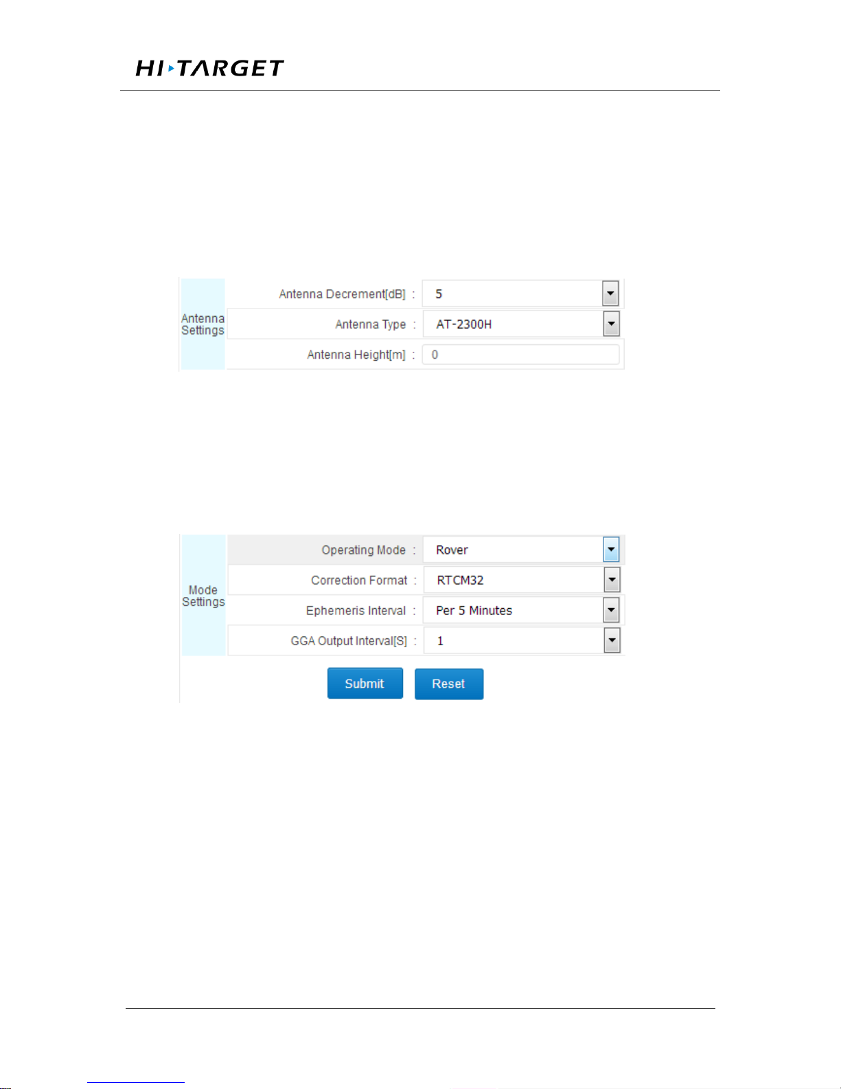
According to the actual parameters of the antenna information, set the antenna
attenuation, antenna type, and antenna height (refer to 【WEB management
system introduced】-【work mode】-【reference station settings】); Figure 4-13:
Figure 4-13 Antenna settings
2. Base settings
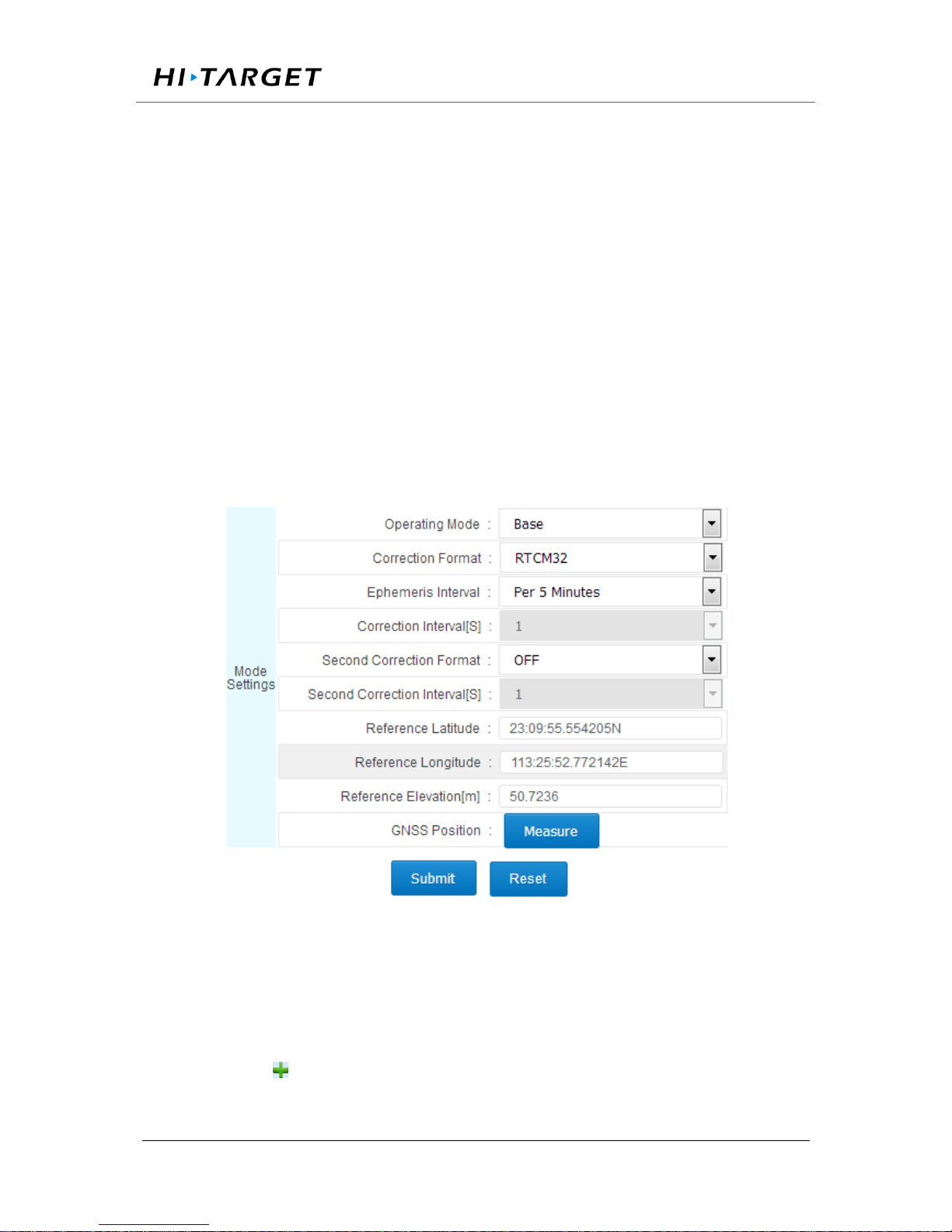
Set the work mode of the reference station as【rover】 and submit it; as shown
in Figure 4-14:
Figure 4-14 Rover Settings
Page 66
Surveying the world,Mapping the future.
ADD: Building13, Tian’An Technology Zone HQ center, No.555, the North of Panyu RD, Panyu District 511400, Guangzhou, China.
Set the work mode of the reference station as 【 Base Station 】 , choose
【Correction Format】according to actual needs (OFF, CMR, RTCM, RTCMV3,
RTCM32, BINEX for selection), ephemeris interval is recommended to select
【every 30 minutes】 (Every 1 minute, every 5 minutes, every 15 minutes, every
30 minutes for selection), manually enter the known latitude and longitude and
elevation, and click 【submit】; Figure 4-15:
Figure 4-15 Base settings
4.7 Add data record
Log in WEB management system interface, click on the data record quick link or
click 【work mode】 - 【data record】to set;
Click the button in the upper left corner of the interface to pop up【Data Logging
Page 67
Surveying the world,Mapping the future.
ADD: Building13, Tian’An Technology Zone HQ center, No.555, the North of Panyu RD, Panyu District 511400, Guangzhou, China.
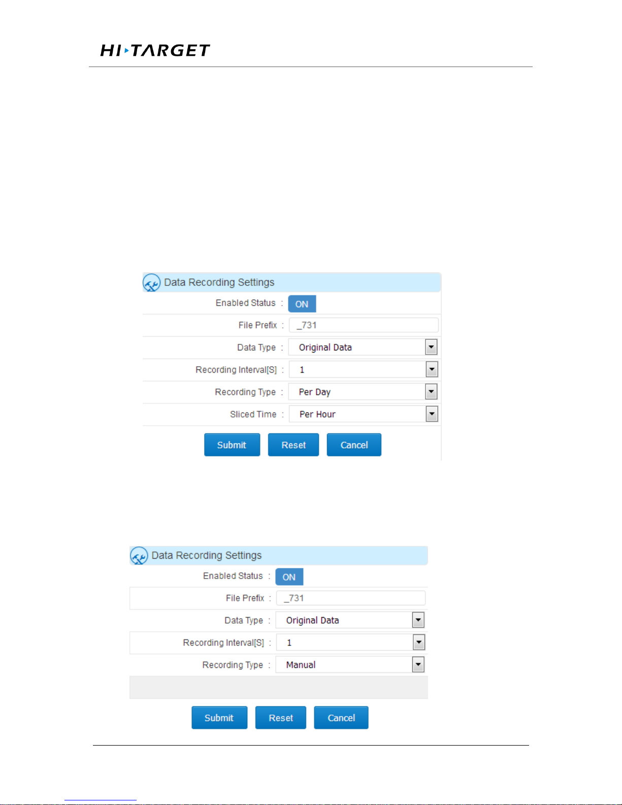
Settings】dialog box, enable the status dial to 【ON】, set the file 【Identification
name】 (the first four digits and the last four of the file is serial numbers added
by the system ) 【Data type】 Select【raw data】 or 【Rinex】 according to
actual needs, 【record interval [S]】is recommended 1.【record】are daily, manual
and planned ways, just click【submit】. Record ways are shown below:
Record every day (24 hours record without break up, or record a file every hour,
or record a file every two hours), as shown in Figure 4-16:
Figure 4-16 Daily Data Logging Settings
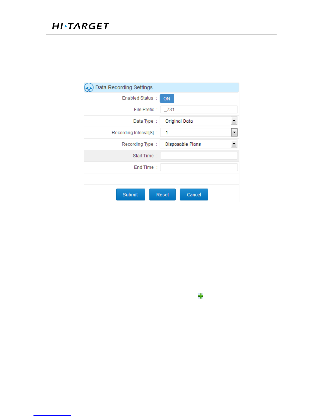
Manual recording (manual control data records to enable or disable), shown in
Figure 4-17:
Page 68
Surveying the world,Mapping the future.
ADD: Building13, Tian’An Technology Zone HQ center, No.555, the North of Panyu RD, Panyu District 511400, Guangzhou, China.
Figure 4-17 Manual data logging settings
Disposable plan records (according to the needs to set the time start and end),
shown in Figure 4-18:
Figure 4-18 Disposable plan data logging settings
4.8 Add network transmission
Log in WEB management system interface, click the network transmission quick
link or click 【work mode】 - 【network transmission】to set;
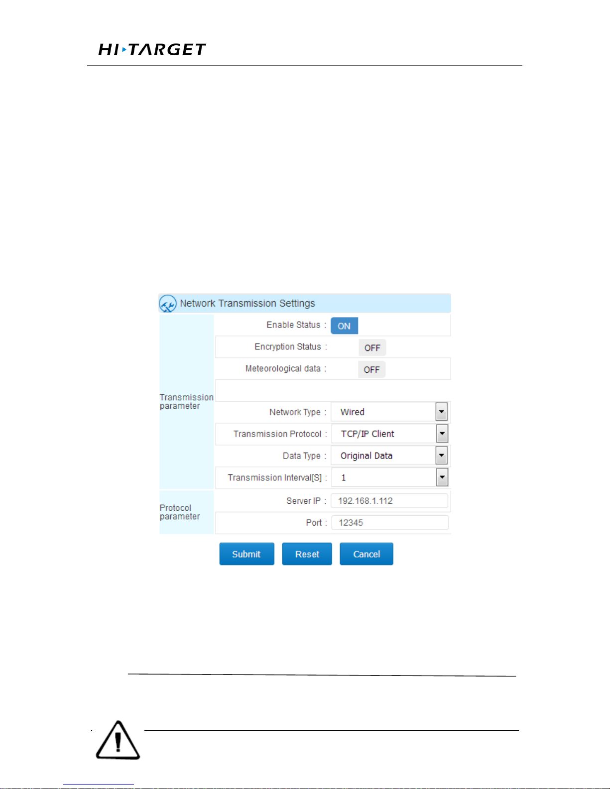
Click the button in the upper left corner of the interface , the 【Network Transfer
Settings】dialog box will pop up, put the state dial to 【ON】, 【Encryption state】
sets According to the actual need , 【Network】 Recommended 【Wired】 (wired、
Wi- Fi、2G / 3G), 【transmission protocol】sets according to the actual need(to
understand the transmission protocol, please go to the 【work mode】 - 【network
transmission】of the【WEB management system introduction】) , 【data type】
Page 69
Surveying the world,Mapping the future.
ADD: Building13, Tian’An Technology Zone HQ center, No.555, the North of Panyu RD, Panyu District 511400, Guangzhou, China.
sets According to the actual needs (choose from raw data, NMEA-0183,
correction data, RS232 serial data, RS485 serial port data ) 【 Transmission
interval [S] 】 only the raw data have This option, recommend to use 1
(0.05,0.1,0.2,0.5,1,2,5,10,15,30,60 transmission interval [S] for the user to
choose), the server IP , Port, user name and other settings are related to
transmission protocol, see the specific【work mode】 -【network transmission】
of the【WEB management system introduced】; set as shown in Figure 4-19:
Figure 4-19 Add network transmission
Notice:
1. Three kinds of network modes can exist at the same time, but the IP
Page 70
Surveying the world,Mapping the future.
ADD: Building13, Tian’An Technology Zone HQ center, No.555, the North of Panyu RD, Panyu District 511400, Guangzhou, China.
address transmitted to the server can not be the same.
2.when opening the second correction output, the 【original data】turn
into the second correction.
4.9 Data download
Normal download
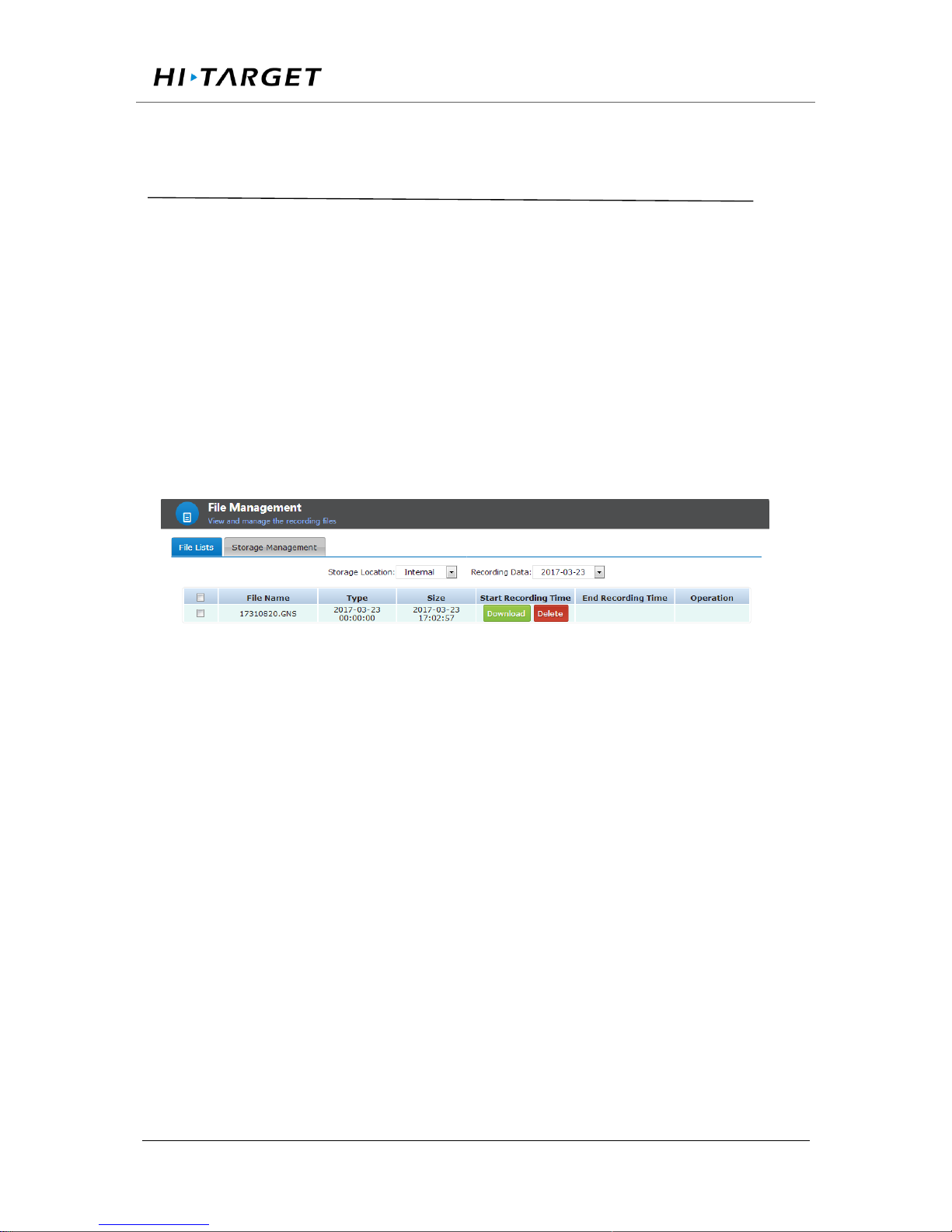
In the WEB management system 【File Management】 - 【File List】, select
the location of the data storage and the date of the record; pop up intraday data
list, click the right side of data list 【operation】-【download】 then download
the corresponding data; as shown in Figure 4-20:
Figure 4-20 Normal data download
FTP download
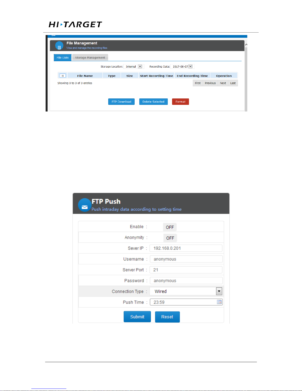
Before FTP download data, make sure the routing and LAN has opened the FTP
port; In the WEB management system 【file management】- 【file list】,click
【FTP download】button, automatically go to the FTP download list; the home
page download list shown in Figure 4-21:
Page 71
Surveying the world,Mapping the future.
ADD: Building13, Tian’An Technology Zone HQ center, No.555, the North of Panyu RD, Panyu District 511400, Guangzhou, China.
Figure 4-21 FTP download directory
Click the catalog folder of the storage (select it according to the actual
requirements), enter the date list, and then click the corresponding date
FTP push
FTP push can periodically push the data file to the server. Set the parameters as
shown in Figure 4-22:
Figure 4-22 FTP push
Page 72

Surveying the world,Mapping the future.
ADD: Building13, Tian’An Technology Zone HQ center, No.555, the North of Panyu RD, Panyu District 511400, Guangzhou, China.
First, enable the FTP push function, set anonymous or non-anonymous user,
server IP and port (data be pushed to FTP server IP and port), push mode (select
cable, Wi-Fi or 3G) and push time, as shown above.
Push time interface for quick selection of time and customization. When the first
click, pop-up time check box; you can click hour to modify hour, pop up hour
selection box, select the desired hour; modify second is the same, and finally click
"OK"; finally,click【submit】. Shown in Figure 4-23:
Figure 4-23 FTP push time selection
U disk download
In order to protect the security of data, a password is needed(the default password
is: 1234. This password can be modified in 【advanced settings】-【Data download
password】)
In the LCD menu, select【Data Download】, click the "Power button" to enter the
password input interface; enter the password, click the "power button", then
display the box into the first underlined, then can modify the first figure of the
password, click the "right button" plus 1, click the "left button" minus 1, after that,
click the "power button" to modify the second password, until password input
Page 73
Surveying the world,Mapping the future.
ADD: Building13, Tian’An Technology Zone HQ center, No.555, the North of Panyu RD, Panyu District 511400, Guangzhou, China.
completely, click the "power button" to enter the download interface, click the
"power button", go to the download days selection, click the left / right button to
change the number of days, click the "Power button" to confirm, and then click
the "power button" to download (before U disk data downloading, make sure the
U disk has been properly installed, or "no U disk"), After the download is done,
the LCD shows "Download Complete";
Notice:
1, When downloading the Rinex file data, you need to download". 15p"
and" .15o" file to a same folder, or the solution will be abnormal;
2, In FTP server local (internal memory) folder, the folder named by
date is for the receiver to collect the raw data and Rinex data; log is
the system log folder; mail folder is the mailbox receive the
corresponding file; lost + found Folder is the system folder;
3, prohibit of use download tools to download.
4, download time is related to the size of file and your network's
connection speed, please be patient. When downloading, you can
close the page and browser, do not disconnect the network or reboot
the device.
4.10 Firmware upgrade
Web page upgrade firmware
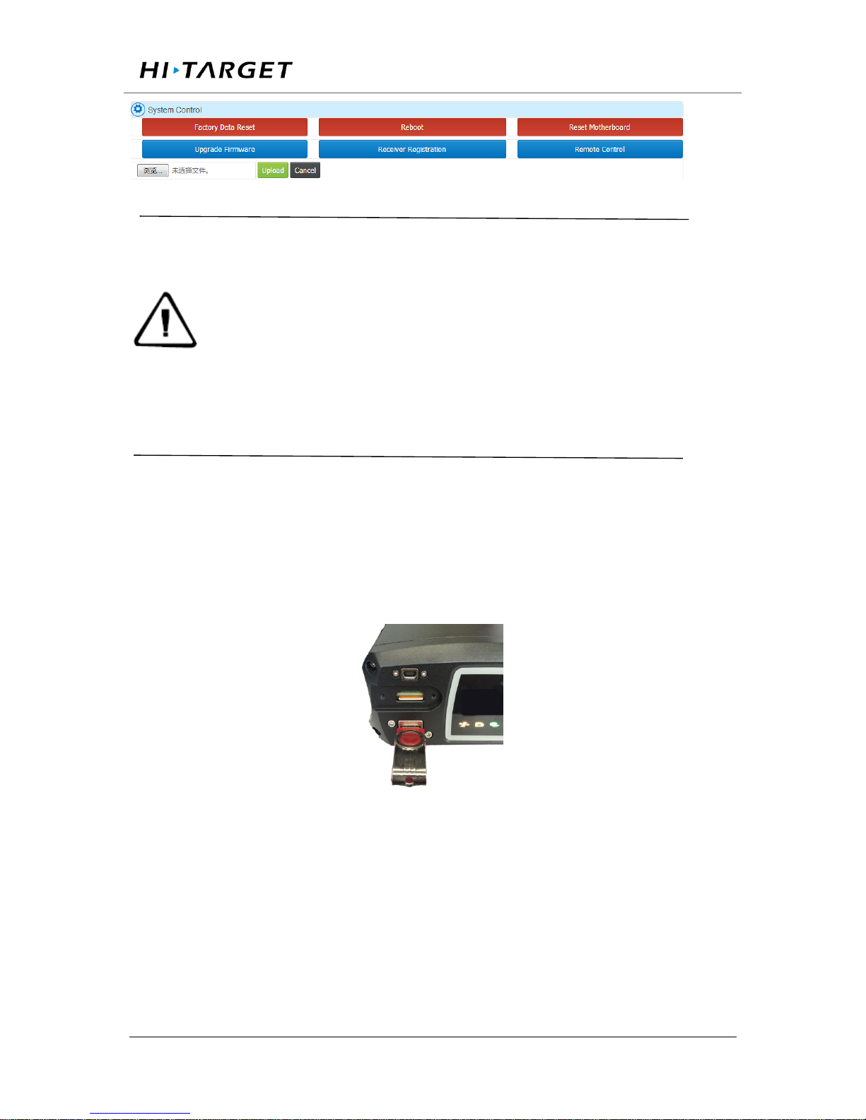
In the WEB management system select 【advanced settings】-【Host settings】
-【System control】click 【Upgrade the firmware】Expand the dialog box as
shown in Figure 4-24
Page 74
Surveying the world,Mapping the future.
ADD: Building13, Tian’An Technology Zone HQ center, No.555, the North of Panyu RD, Panyu District 511400, Guangzhou, China.
Figure 4-24 Firmware upgrade
Notice:
1.update the firmware package was named "VNet6 Plus Update.bin"
(without the quotation marks). Please do not modify this file name, or
upgrade the firmware fails;
2.upload firmware package, please do not close the browser, or
upgrade the firmware fails.
3.the time of uploading the firmware package related to your network
environment, long pass under LAN is about 10 seconds.
U disk upgrade firmware
Firstly, copy the firmware package "VNet10_Update.bin" that needed to be
upgraded to the U disk root directory, and then insert the U disk into the UAB-A
port at the front panel of the receiver; as shown in Figure 4-25:
Figure 4-25 U disk installation diagram
In the LCD menu select【System settings】-【Upgrade the firmware】, click "Power
button", Pop-up prompt box "Please confirm the insertion of U disk" after
confirmation, Click the "Power button" prompt sending successfully (if U disk is
not inserted identify as error, it will prompt "no U disk" and return to 【upgrade
Page 75
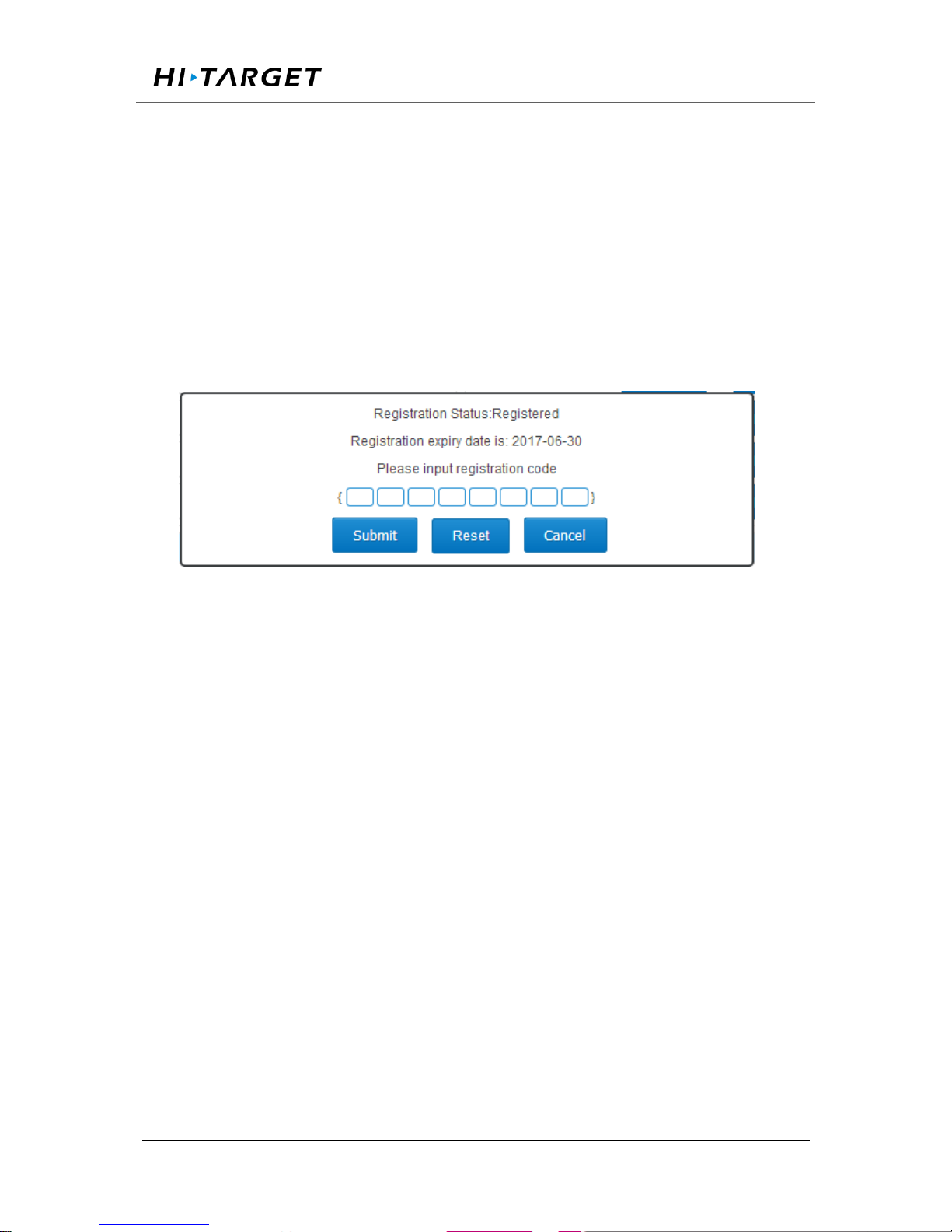
Surveying the world,Mapping the future.
ADD: Building13, Tian’An Technology Zone HQ center, No.555, the North of Panyu RD, Panyu District 511400, Guangzhou, China.
firmware】 selection interface) about 1 minute later, the receiver restart that
represents the success of the upgrade.
4.11 Register the receiver
In the WEB management system select 【advanced settings】-【Host settings】
-【System control】click 【Receiver registration】Expand the dialog box as shown
in Figure 4-26
Figure 4-26 Receiver Registration
The receiver License format is 24 digits, divided into 8 groups, each group
contains 3. After entering the registration code just enter the registration code (the
system will ignore blanks of the registration code while entering), confirm it and
click 【submit】.
Diagnosis analysis and troubleshooting of common faults
5.1 The system starts normally, while lock star light SV is off
1.Check the environment of GNSS external antenna, GNSS external antenna
installation is downward, whether reference to the instructions in the overview
and precaution for distribution and installation;
Page 76

Surveying the world,Mapping the future.
ADD: Building13, Tian’An Technology Zone HQ center, No.555, the North of Panyu RD, Panyu District 511400, Guangzhou, China.
2.Check the registration code is expired or not, such as the validity of WEB
management system and if the body number become red, means the registration
code has expired, please contact related staff of HI-TARGET to apply for
registration code, and log VNet series Web management system registered
receiver;
3.Check the GNSS antenna cable at both ends and check the connection between
GNSS receiver and GNSS antenna is tight or not, if loose please tighten, and wait
for about 30 seconds;
4. Monitor whether the GNSS antenna cable is connected to the GNSS ANT port,
not the WIFI ANT port.
5.2 The GNSS receiver is working properly and the terminal software has been
deployed, but the network transmission status is connecting
1.Check the connected network mode, network protocol and IP address and port
is correct;
2.Such as the network mode for the 3G, check the network parameters of the 3G
network is open; and make sure the local network environment is right, you can
use your mobile phone to check it. Make sure the SIM card is Unicom 3G / 2G or
mobile 2G card, and the data traffic is normal, that is activated and no arrears.
5.3. GNSS receiver is working properly, network transmission is connected, but
the raw data output frequency is incorrect
Use the network debugging assistant to receive data to check the data output
frequency is correct or not, such as the output frequency is less than the seted
Page 77

Surveying the world,Mapping the future.
ADD: Building13, Tian’An Technology Zone HQ center, No.555, the North of Panyu RD, Panyu District 511400, Guangzhou, China.
frequency,make sure whether to open a record of a data record, and record the
frequency is greater than or equal to the network transmission of raw data
frequency, and open the automatic removal function.
Establish several data records, at the beginning the recording is normal, but
become not normal later
1. The late record is intermittent; make sure whether the power supply is normal,
if the battery is 12V power supply, the battery voltage should not less than 10.5V;
if use switching power supply , make sure the output power is greater than 15W.
2. No record later; check whether the registration is expired, if not, check whether
the GNSS receiver lock satellites, if so check the space of storage capacity.
5.4 Network cable connection is normal, but can not log on and visit the VNet
series (ground enhancement) Web management system;
1.Make sure whether the computer settings are set according to the network
settings and wired network settings in the manual.
2. The computer can ping the GNSS receiver, but can not access; turn off the
firewall and anti-virus software.
3.Make sure the IP inputted is correct. If can't just double-click the [power button]
to see the current IP address.
Page 78

Surveying the world,Mapping the future.
ADD: Building13, Tian’An Technology Zone HQ center, No.555, the North of Panyu RD, Panyu District 511400, Guangzhou, China.
Chapter 5 Appendix
5.1 Reset
Major items
content
The parameters after recovery
Reference station
Site name
HI-TAGET High precision GNSS receiver
UTC Time zone
UTC+8
Antenna attenuation
[dB]
5
Antenna model
AT-1200B
Antenna high [m]
0
Reference station
work mode
Rover
Ephemeris interval
Every 30min
Correction data format
RTCMV3
Satellite system
All open
Height cutoff angle
10°
Receiver function
Storage device
Internal storage
2G/3G internet
OFF
RS232/RS485 Serial
OFF
Page 79

Surveying the world,Mapping the future.
ADD: Building13, Tian’An Technology Zone HQ center, No.555, the North of Panyu RD, Panyu District 511400, Guangzhou, China.
port
Server port settings
80
Firewall
OFF
Time input
OFF
External clock input
OFF
PPS output
OFF
FTPPush
OFF
User
Only retain administrator privileges, and
restore the default password
Automatic cleaning
time after full
1 day
Small five-core serial
port pointing
Motherboard 1COM2
Power output
OFF
Data
management
Network transmission
Delete all
Data record
Delete all
Internal data
Delete all
Log management
Delete all
5.2 VNet product technical performance parameters table
Model
VNet10
VNet9
VNet6
GNSS
characte-
ristic
Number of channels:
384*2(384)
Number of channels:
384+220
Number of channels:
220
GPS:L1、L2、L5
GLONASS: L1、L2
BDS:B1、B2、B3
GPS:L1、L2、L5
GLONASS: L1、L2
BDS:B1、B2、B3
GALILEO:L1BOC,E5
A,
E5B,E5AltBOC
SBAS:L1C/A,L5
GPS:L1、L2、L5
GLONASS: L1、L2
BDS:B1、B2
GALILEO:L1BOC,E5
A,
E5B,E5AltBOC
SBAS:L1C/A,L5
positioning accuracy
RTK Horizontal accuracy:±(8mm+1X10⁻⁶D)
RTK Vertical accuracy:±(15mm+1X10⁻⁶D)
Static Horizontal accuracy:±(2.5mm+1X10⁻⁶D)
Static vertical precision:±(5.0mm+1X10⁻⁶D)
Initialization time
typical <10S
Initialize reliability
>99.9%
Port
3 RS232 port
1 USB port
1 WiFi、Bluetooth communication port
1 3G/2G Communication port
Page 80
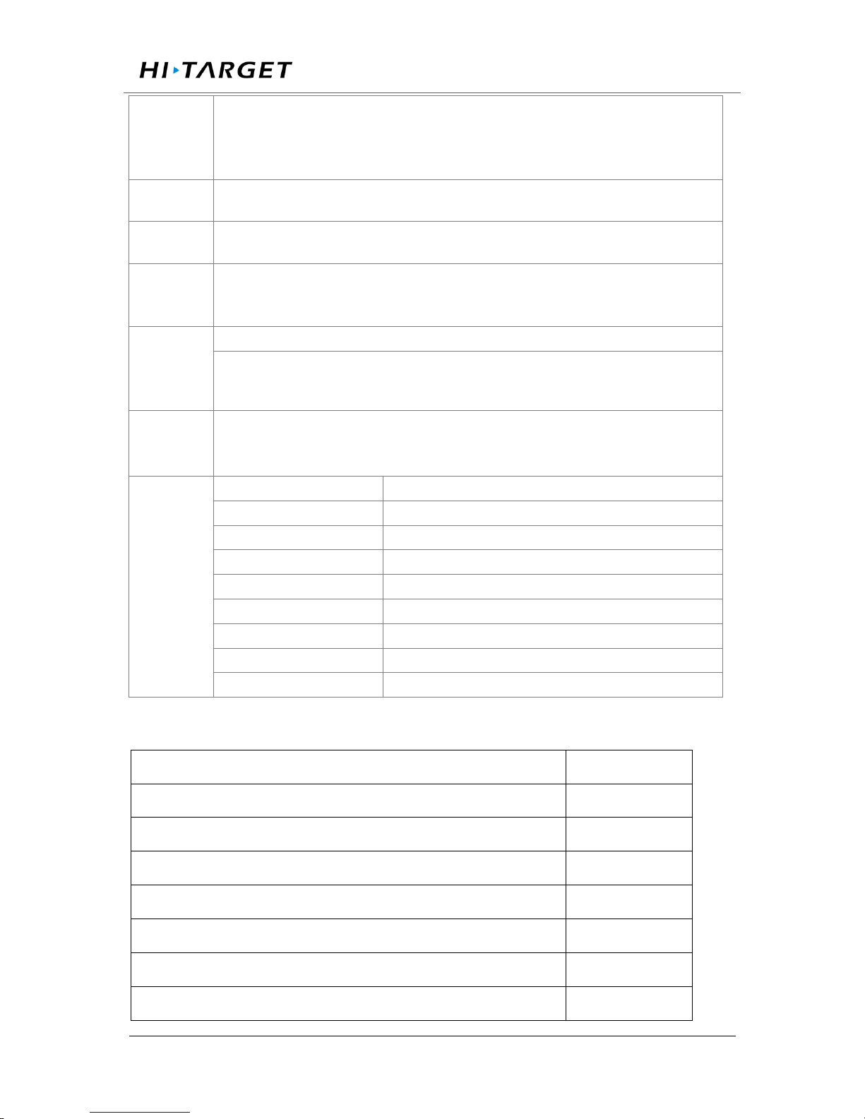
Surveying the world,Mapping the future.
ADD: Building13, Tian’An Technology Zone HQ center, No.555, the North of Panyu RD, Panyu District 511400, Guangzhou, China.
1 RS485/RS422 port
1 Ethernet interface
1 External clock interface
1 PPS Output Interface
Internal
storage
64GB
External
storage
Maximum support is not less than 1TB
Correction
data
format
CMR、RTCM2.x、RTCM3.0、RTCM3.2
Human-
computer
interactio-
n
WEB Web management system
LCD、Indicator, button operating system
Battery
External power supply:7VDC~36VDC(2)
Built-in battery:24h Continuous work (related to configuration)
Power consumption: ≤ 4W
Environm-
ental
adaptabi-
lity
Working temperature
-40℃~75℃
storage temperature
-40℃~80℃
Relative humidity
100%
Protection class
IP67
Anti-corrosion
Satisfy GJB150.11
vibration
Satisfy GJB_1032
Impact
Satisfy JB/T 9329 30g 3 Times / axis
collision
Satisfy JB/T 9329 10g 1000 Times
Drop
Satisfy GB-T2423.8 protect from 1 meter’s drop
5.3 Standard configuration table
Item Name
Number
GNSS Receiver
1
Power Adapter
1
AC power cord
1
Vnet Data cable
1
Direct cable
1
Vnet Packaging cartons
1
Vnet10 Packing lining
1
Page 81
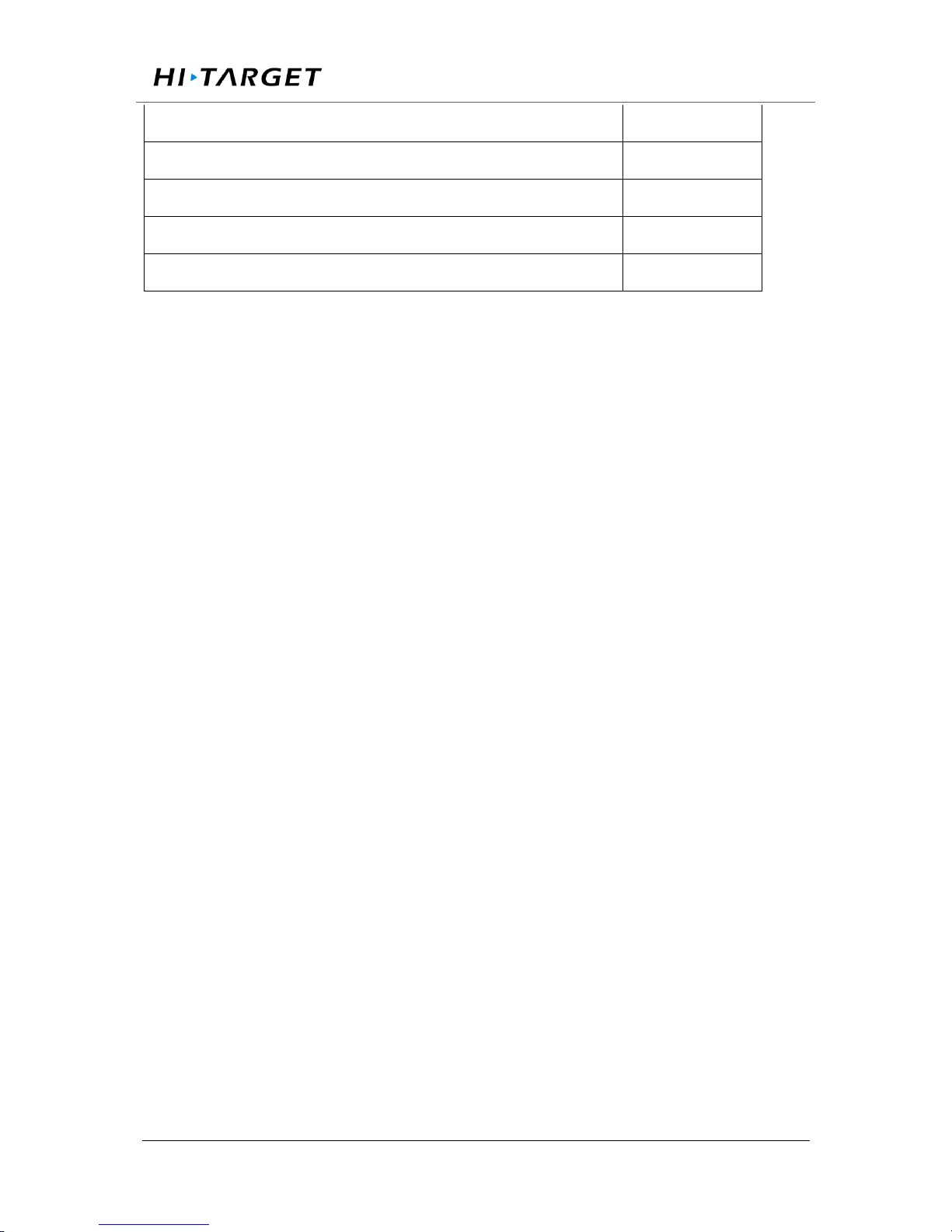
Surveying the world,Mapping the future.
ADD: Building13, Tian’An Technology Zone HQ center, No.555, the North of Panyu RD, Panyu District 511400, Guangzhou, China.
Ground reinforcement system product manual
1
Aluminum lugs
3
Cross plate head machine wire [M3*6]
3
Warranty Card
1
Factory inspection certificate
1
 Loading...