

Page 1

Hi-Target V60 GNSS RTK Receiver
User Guide
Page 2
The introduction is applicable to Hi-Target V60 products. V60 is a new
type of GNSS receiver used for measurement. The introduction describes
how to install, set and use V60 products.
In order to help you better use Hi-Target s eries products, Hi-Target
suggests you carefully reading the instruction. If you are unfamiliar with
V60 products, please refer to www.hi-target.com.cn/en/
Tips for safe use
Note-the contents here gene rally are special operations, needing
your special attention.Pleas e read the contents carefully.
Warni ng-the contents here generally are very impo rtant. In case
of failing to operate based on warni ng contents, it will damage the
machine, lose the data, break down t he system and endanger
personal safety.
Before using the products, please carefully read the operating
instruction, and it will help you better use the product. Hi-Target
Surveying Instrument Co., Ltd will not assume the responsibilities if
you fail to operate the product according to the requirements in
operating instruction, or operate the product wrongly because of failing
to understand the operating instruction.
Hi-Target is committed to constantly perfect product functions and
performance, improve service quality and reserve the rights to change
the contents in operating instruction without separate notice.
We have checked the consistency between contents in instruction and
software & hardware, without eliminating the possibility of deviation.
The pictures in operating instruction are only used for reference. In case
of inconformity with products, the products shall prevail.
Exclusions
Preface
Introduction
Page 3

1 Product Introduction
1 Product Introduction
Preface
Product Characteristics
Cautions for Use
.... . . .... . . ... . . .... . . .... . . ... . . .... . . .... . .... .
1
2
2
3
4
5
5
7
7
9
11
12
12
13
14
18
19
25
25
28
31
31
31
32
34
35
35
37
.... . . .... . . ... . . .... . . .... . . ... . . ....
.... . . .... . . ... . . .... . . .... . . ... . . .... . . ...
.... . . .... . . ... . . .... . . .... . . ... . . .... . .
.... . . .... . . ... . . .... . . .... . . ... . . .... . . .... .
.... . . .... . . ... . . .... . . .... . . ... . . .... . . .... . .
.... . . .... . . ... . . .... . . .... . . ... . . .... . . .... .
.... . . .... . . ... . . .... . . .... . . ... . . .... . . .... . ....
.... . . .... . . ... . . .... . . .... . . ... . .
.... . . .... . . ... . . .... . . .... . . ... . . .... . . .
.... . . .... . . ... . . .... . . .... . . ..
.... . . .... . . ... . . .... . . .... . . ... . . .... . . .... .
.... . . .... . . ... . . .... . . .... . . ... . . .... . . .... .
.... . . .... . . ... . . .... . . .... . . ... . . .... . . ....
.... . . .... . . ... . . .... . . .... . . ... . . ....
.... . . .... . . ... . . .... . . .... . . ... . . .... .
.... . . .... . . ... . . .... . . .... . . ... . . .... . . .
.... . . .... . . ... . . .... . . .... . . ... . . .... . . ..
.... . . .... . . ... . . .... . . .... . . ... . . .... . . .... .
.... . . .... . . ... . . .... . . .... . . ... . . .... . .
.... . . .... . . ... . . .... . . .... . . ... . . .... . . .... . ...
.........................................
.....................................
........................................
......................
.... . . .... . . ... . . .... . . .... . . ... . . .... . . .... . .... .
.... . . .... . . ... . . .... . . .... . . ... . . .... . . .
.... . . .... . . ... . . .... . . .... . . ... . . ....
Content
40
41
41
41
.... . . .... . . ... . . .... . . .... . . ... . . .... . . .... . ..
.... . . .... . . ... . . .... . . .... . . ... . . .... . . .
...........................................................
38
.... . . .... . . ... . . .... . . .
.... . . .... . . ... . . .... . . .... . . ... . . .... . . .... . ..
2 Introductions to Receiver
Receiver Appearance
Control Panel
Upper Cover
Bottom Cover
Five-core and Eight-core Sockets
Batteries
Environmental Requirements
Electronic Jamming
3 Elementary Operation
Power Supply
Control Panel
Key Functions
Start and Stop Receiver
SIM card/USIM Card
Radio
Static Data Storage
RTK Data storage
Reset receiver
Formatting Receiver
Firmware
4 Static Collection and Data Transmission
Preface
Static Measurement
U Disk Data Download
Operations of Static Management Software
5 Technical Parameters
GNSS Part
Receiver Precision
UHF Radio
Interface
Physical characteristics
Environment
42
42
42
.... . . .... . . ... . . .... . . .... . . ... . . ....
.... . . .... . . ... . . .... . . .... . . ... . . .... . . .... . ....
.... . . .... . . ... . . .... . . .... . . ... . . .... . . .... .
.... . . .... . . ... . . .... . . .... . . ... . . .... . . .... . .... . .
27
Page 4

6 Socket and Main Accessories
Preface
Difference Antenna
Y-type Data Cable
DDTHPB External Radio
44
44
43
45
48
45
.... . . .... . . ... . . .... . . .... . . ... . . .... . . .... . .... .
49
.... . . .... . . ... . . .... . . .... . . ... . . .... . . .
..............................................
.... . . .... . . ... . . .... . . .... . . ... . . .... . . ..
.... . . .... . . ... . . .... . . .... . . ... . . ...
.........
Annex ed Table 1 Defaulted Frequency Table upon D elivery
Annex ed Table 2 Instructions of Indicator Lights in Control Panel
Content
Page 5

C H A P T E R
1
Product Introduction
This chapter describes:
■
Preface
Product characteristics
Cautions for use
■
■
Hi-Target V60 GNSS RTK Receiver User Guide 1
Page 6
2 Hi-Target V60 GNSS RTK Receiver User Guide
Preface
V60 is a new type of GNSS receiver used for measurement pushed forward
by Hi-Target recently. The receiver is provided with 1G mass storage and
one SD card extendable slot, which can record static data in forms of GNS
and Rinex simultaneously. With brand new appearance design and
optimized internal structure, the product extends the design style of
previous products, making it cope with various complex conditions
outside. The product has self-diagnostic function, which can intelligently
monitor the immediate situations of various software and hardware during
operation process; the product adopts brand new high-precision RTK
system on color liquid crystal screen with modular design. The product
boasts stable and built-in UHF radio and GPRS network module, which
can exchange difference transport module according to customer
requirements and seamlessly connect CORS network system in main
manufactures.
Warni ng-the instruction represents no standar d configuration.
The articles within the box can be adj usted according to differe nt
user requirements. The specific configuration shall be sub ject to
the outgoing list upon purchasin g. The suggestions before us ing
the machine: check whether the pro duct package is damaged;
please open the package carefull y and confirm whether the articles
are consistent with outgoing lis t; in case of loss or damage in the
product and its accessories, ple ase immediately contact with local
office or dea lers; please carefully read the operating instr uction
before carrying, transportin g and using the product.
Apply multi-satellite system and multi-frequency GNSS unit;
support BDS, GPS a nd GLONASS system navigation and
positioning
Internally install 1G mass memory; support SD card data storage,
32GB as a maximum
Internally install a transceiver; then base and rover can be
exchange completely
GPRS Communication function:
With high-capacity lithium battery, the product can meet long-time
operation requirements outside
Product Characteristics
■
■
■
■
■
1 Product Introduction
Page 7
Product Introduction 1
Intelligent voice
Intelligent self-diagnostic function
Function of accelerating and express upgrading
Static data are stored in two formats (*.GNS / RINEX Data)
128x64 resolution; 1.54-inch liquid crystal display The user can
flexibly set the instrument and observe the operations of
instrument through display
As a precise instrument, the receiver shall be used and maintained
carefully regardless of the materials resistant to chemical agent and
impact.
Warni ng-the receiver shall be in stipulated tempe rature range
upon using and storage. The detailed requirements are shown in
Chapter 5: Tech nical Parameters Environment.
Cautions for Use
In order to guarantee the quality of continuous tracking observation and
satellite signals, it is required that the overhead observation station shall
be open, without flaky barriers above 15° elevating angle in order to
diminish the interference of electromagnetic wave to GNSS satellite
signals, the observation station shall be free form strong electromagnetic
wave within the range of 200m, such as television tower, microware
station and high-voltage transmission line in order to avoid or reduce
multipath effect, the observation station shall be far away from the terrain
and ground features with strong reflection against electromagnetic wave
signal, such as high-rise buildings, waters, etc.
■
■
■
■
■
Hi-Target V60 GNSS RTK Receiver User Guide 3
Page 8

C H A P T E R
2
This chapter describes:
Receiver appearance
Control panel
Upper cover
Bottom cover
Five-core and eight-core sockets
Batteries
Environmental requirements
Electronic jamming
■
■
■
■
■
■
■
■
Introductions to Receiver
4 Hi-Target V60 GNSS RTK Receiver User Guide
Page 9
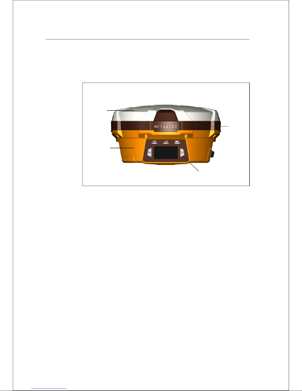
The product appearance is divided into four sections, upper cover, bottom
cover, guard circle and control panel.
Receiver Appearance
Control
panel
Upper
cover
Bottom
cover
Guard
circle
Figure 2-1
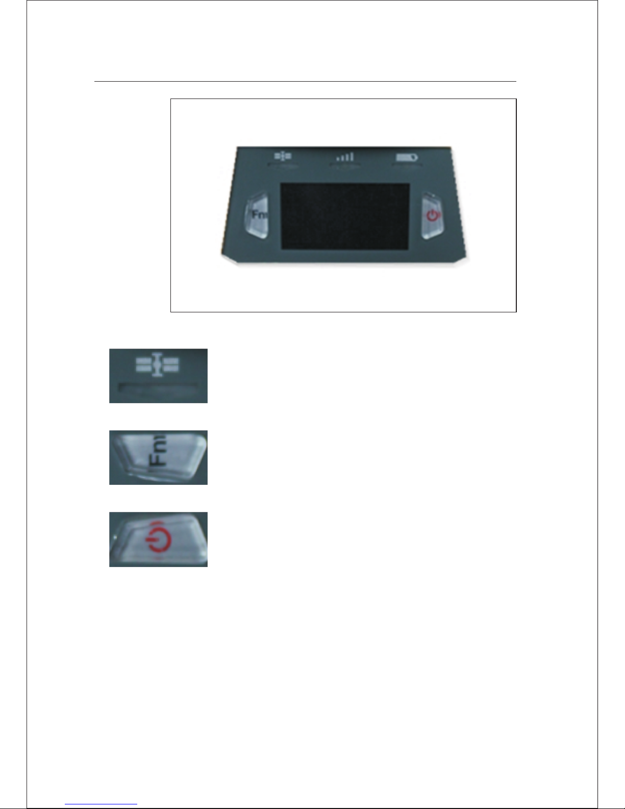
The control panel includes Fn key (function key), power button, LED
display and 3 indicator lights which are satellite light, status light
(bi-color light) and power light (bi-color light). Two buttons cover all
functions of V60 receiver setting.
Control Panel
Hi-Target V60 GNSS RTK Receiver User Guide 5
Introductions to Receiver 2
Page 10
2 Introductions to Receiver
Satellite light (green light), status light (red and green light)
and power light (red and green light).
Function key: set work mode, data link, UHF radio channel,
satellite elevation, sampling interval, reset receiver, etc.
Power button of startup & shutdown: set confirmation and
inquire current work mode.
6 Hi-Target V60 GNSS RTK Receiver User Guide
Figure 2-2
Page 11
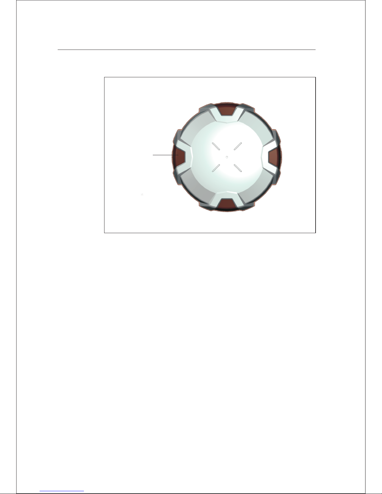
Upper Cover
Convex
plate
Include battery slot, five-core socket, eight-core socket, radio antenna
interface, trumpet, etc.
Bottom Cover
Hi-Target V60 GNSS RTK Receiver User Guide 7
Introductions to Receiver 2
Page 12
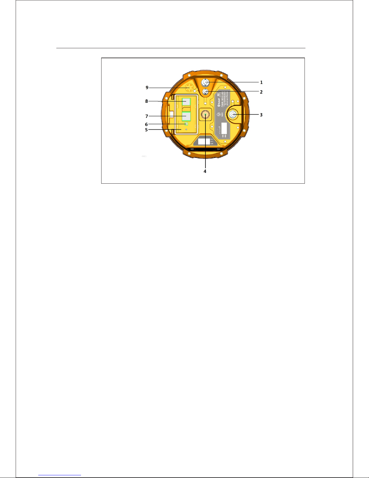
1. Eight-core socket and protect ion plug
2. Five-core socket and protecti on plug
3. UHF radio antenna interface
4. Connecting screw
5. Battery slot
6. Vibratin g needle power socket
7. SIM slot
8. SD card slot
9. Trumpet
8 Hi-Target V60 GNSS RTK Receiver User Guide
2 Introductions to Receiver
Figure 2-3
Eight-core socket: it is used to connect the receiver, computer,
handbook and external power supply, and load and delete the data
Five-core socket: it is used to connect the receiver, external data
chain and external power
UHF radio antenna interface: it is used to connect the internal UHF
radio antenna for transmission or receiving
Connecting screw: it is used to fasten the instrument to base or
centering rod
Battery slot: it is used to place lithium battery
■
■
■
■
■
Page 13
Vibrating needle power socket: it is used to connect the lithium
battery and host
SIM card slot: when communicating with GSM data, it is used to
place SIM card
SD card slot: it is used to place SD card, which can store massive
static data
Trumpet: timely operate the instrument and broadcast the s tatus
with voice
Protection plug: it is used to prevent dust in interface
Note:
1. If it is unnecessary to use five-core socket, eigh t-core socket
and difference antenna interface, please cover the rubber plug
to prevent dust.
2. In case of inflowing, the trumpet may be silent or hoarse, which
will recover normally after dryi ng.
Five-core and Eight-core Sockets
Figure 2-4
■
■
■
Hi-Target V60 GNSS RTK Receiver User Guide 9
Introductions to Receiver 2
■
■
Page 14
Jag
Jag
Figure 2-5
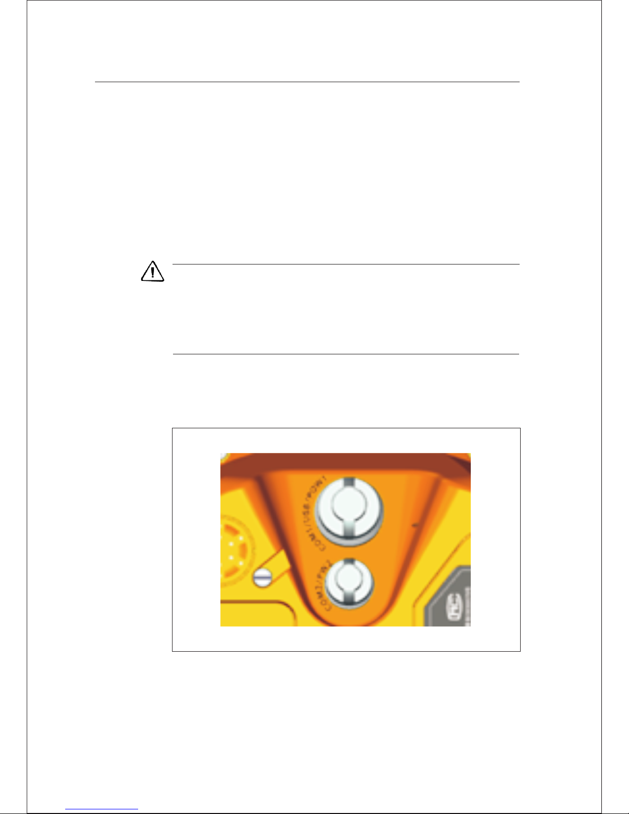
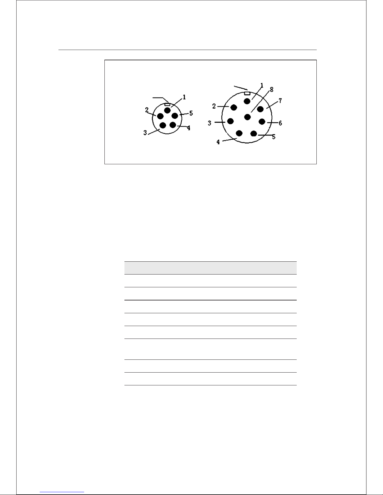
1. Five-core socket: it is also called as COM2/PW2, which is used to
connect the host and external data chain, and external power supply.
2. Eight-core socket: it is also called as COM1/USB/PW1, which is
used to connect the computer and controller, set parameters,
download and delete files.
Table 2.1 Description of five-core and eight-core socket signals
Small five-core signal Large eight-core signal
1 Ground GND 1 Data int o RXD
2 Ground GND 2 USB D-
3 Power into Vi n 3 USB D+
4 Data into RXD 4 USB V+
5 Data out TXD 5 Power into Vin
6
Cable insertion mark
GC-2
7 Data out TXD
8 Gr ound GND
10 Hi-Target V60 GNSS RTK Receiver User Guide
2 Introductions to Receiver
Page 15
Symbol of cable insertion: GC-2 is cable interior ground
All round sockets are numbered anticlockwise in positive face; all
round plugs are numbered anticlockwise in weld face
All TXD and RXD are described by the receiver. EXD is the transmit
data line of receiver; RXD is the receive data line of receiver
The signal of computer serial DB9 pin joint: 2 (RXD computer data
receiving signal line); 3. (TXD computer data transmit signal line)
and 5. (GND signal earth). “2 receiving 3 sending” for short
Note-It refers to the socket front of host botto m in the face of host
(weld face of socket).
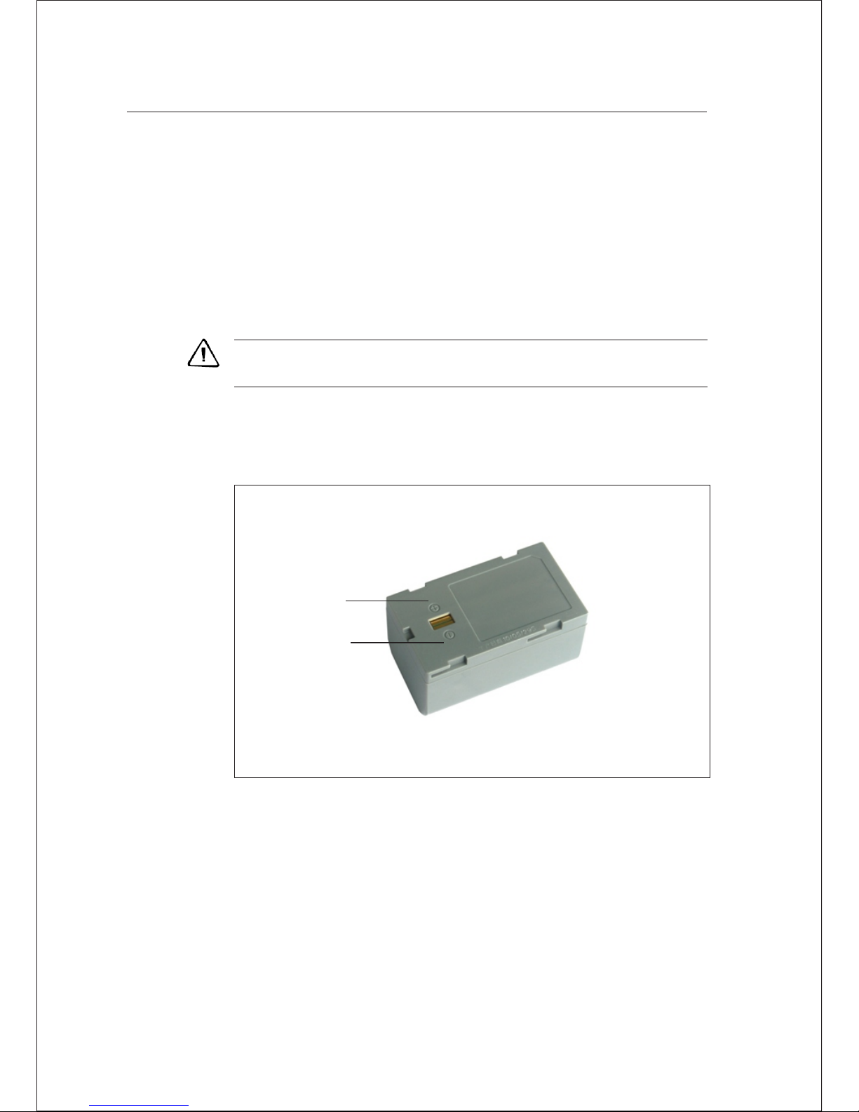
Batteries
Positive
pole
Negative
pole
Figure 2- 6
■
■
■
■
Hi-Target V60 GNSS RTK Receiver User Guide 11
Introductions to Receiver 2
Page 16

Environmental Requirements
The receiver shall operate in dry working environment regardless of
waterproof materials. In order to advance the stability and service cycle
of receiver, the receiver shall be prevented from extreme environment,
such as:
Moisture
Temperature s above 65 degrees centigrade
Below - 40 degrees centigrade
Corrosive liquids or gases
The receiver shall not be installed in the place nea r to strong electric
power and interference signal, such as:
Electronic Jamming
Oil duct (spark plugs)
Generator
Battery-operated motor cycle
DC-AC power supply changeover equipment
Signal transmitting station (tower)
Power supply
■
■
■
■
■
■
■
■
12 Hi-Target V60 GNSS RTK Receiver User Guide
2 Introductions to Receiver
■
■
Page 17

C H A P T E R
3
Elementary Operation
This chapter describes:
■
■
■
■
■
■
■
■
Power supply
Control panel
Function Key
Start and stop receiver
SIM card/USIM card
Radio
Static data storage
RTK data storage
Reset receiver
Formatting receiver
Firmware
■
■
■
Hi-Target V60 GNSS RTK Receiver User Guide 13
Page 18
3 Elementary Operation
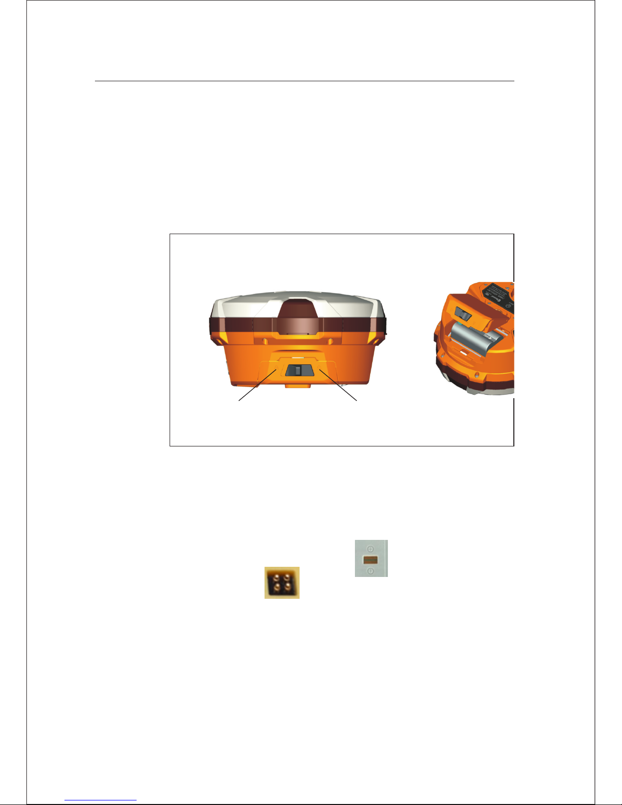
Installation: obliquely insert the two raised areas on battery cover plate
into the slot; press downwards and fasten the battery cover upon the
sound of “bang”; place the pushing and dialing key in locking status.
Removal: move the pushing and dialing key to deblocking status; the
battery cover will be popped automatically and opened.
Power Supply
Battery cover plate installati on and removal
Unlock
state
Lock
state
Installation:
Battery installation and removal
1. Align “open” side at battery slot with vibrating needle
power socket .
2. Lightly push in towards “close” side (as shown by red arrow)
to install battery.
Figure 3-1
14 Hi-Target V60 GNSS RTK Receiver User Guide
Page 19
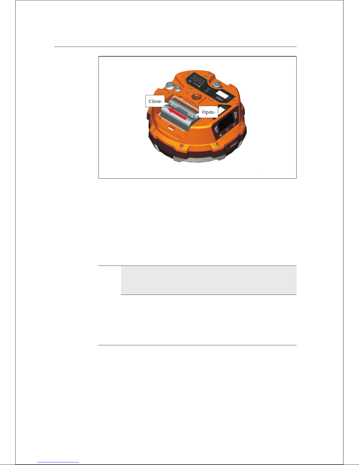
Figure 3-2
Removal: push out along with “open” side and pour out the battery to
dismantle the battery.
Power supply mode
Table 3.1 Pow er supply mode of V60 receiver
Power Power Built-in lithium bat tery, eight-core socket
supply supply mod e /five -core socket external power supply
Scope of DC power: 6V-28V
Power
Supply
Hi-Target V60 GNSS RTK Receiver User Guide 15
Elementary Operation 3
Page 20
The receiver can also supply power through eight-core socket/five-core
socket external power supply.
Where:
The receiver will automatically start after en ergizing eight-core socket
external power supply.
The receiver will start through pressing the power button on control
panel after energizing five-core socket external power supply.
The external voltage range of GSM operation mode and UHF mobile
station is DC 6-28V. The current shall be more than 1,000 mA. Upon
external power supply, the host will automatically detect the voltage of
lithium battery and external power supply, and supply power cho osing
higher voltage. As for external power supply, it shall use the special
power specified by Hi-Target.
Note:
1. The service life of lithium battery will decrease along with the
decreasein temperature and inc rease in charging-discharging
times.A new 5000 mAh li thium battery can be used for 12 hours
upon collection of static data, 9 hours upon GPRS rov er;
7 hours upon internal radio transm it base station.
2. After using up, it shall charge the ba ttery within 24 hours, or the
battery performance will be dama ged.
3. When the battery is not used for a long time, please charge
once every month to prolong the service life of battery.
16 Hi-Target V60 GNSS RTK Receiver User Guide
3 Elementary Operation
Page 21
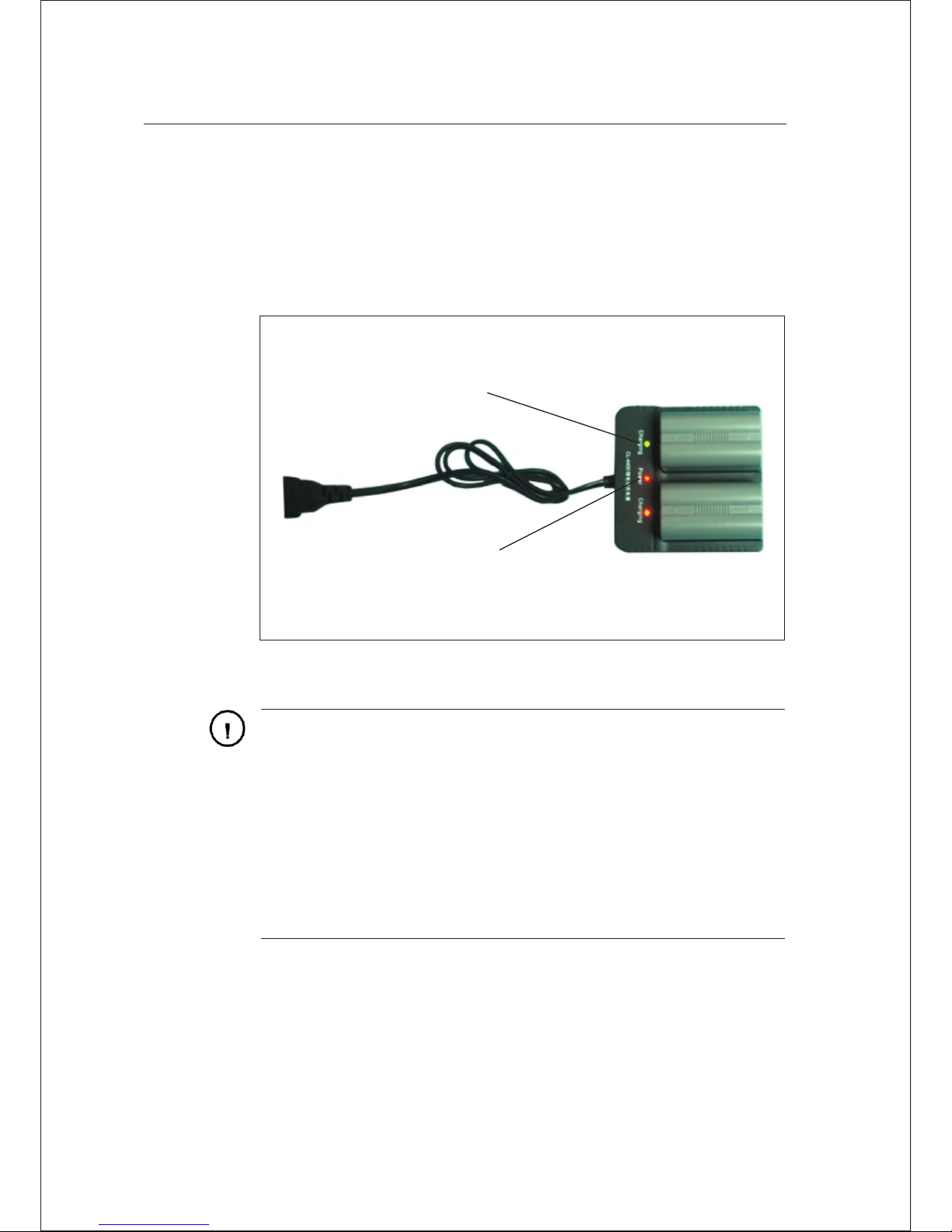
Recharge
BL-5000 lithium battery shall use Hi-Target CL-4400 lithium battery
charger to charge. About 7 hours of charging time CL-4400 charger is
designed with charge lamp. The lamp is red during charging process and
turns green upon finishing charging . The battery is full continue
charging for another 1-1.5 hours.
Charging
lamp
Charger
lamp
Figure 3-3
Warni ng:
1. only the battery and charger conf igured by the manufacturer
can be used; the battery shall not be thrown into fire or u sed in
metal short circuit electrode.
2. It shall stop using in case of heatin g, deformation, liquid
leakage, smelling or other abnor mal reactions during using,
charging or storage process. Che ck whether the battery and
charger are in failure.
3. If the service time of battery is shortened or the battery is
aged,it shall exchange new batte ry.
Hi-Target V60 GNSS RTK Receiver User Guide 17
Elementary Operation 3
Page 22
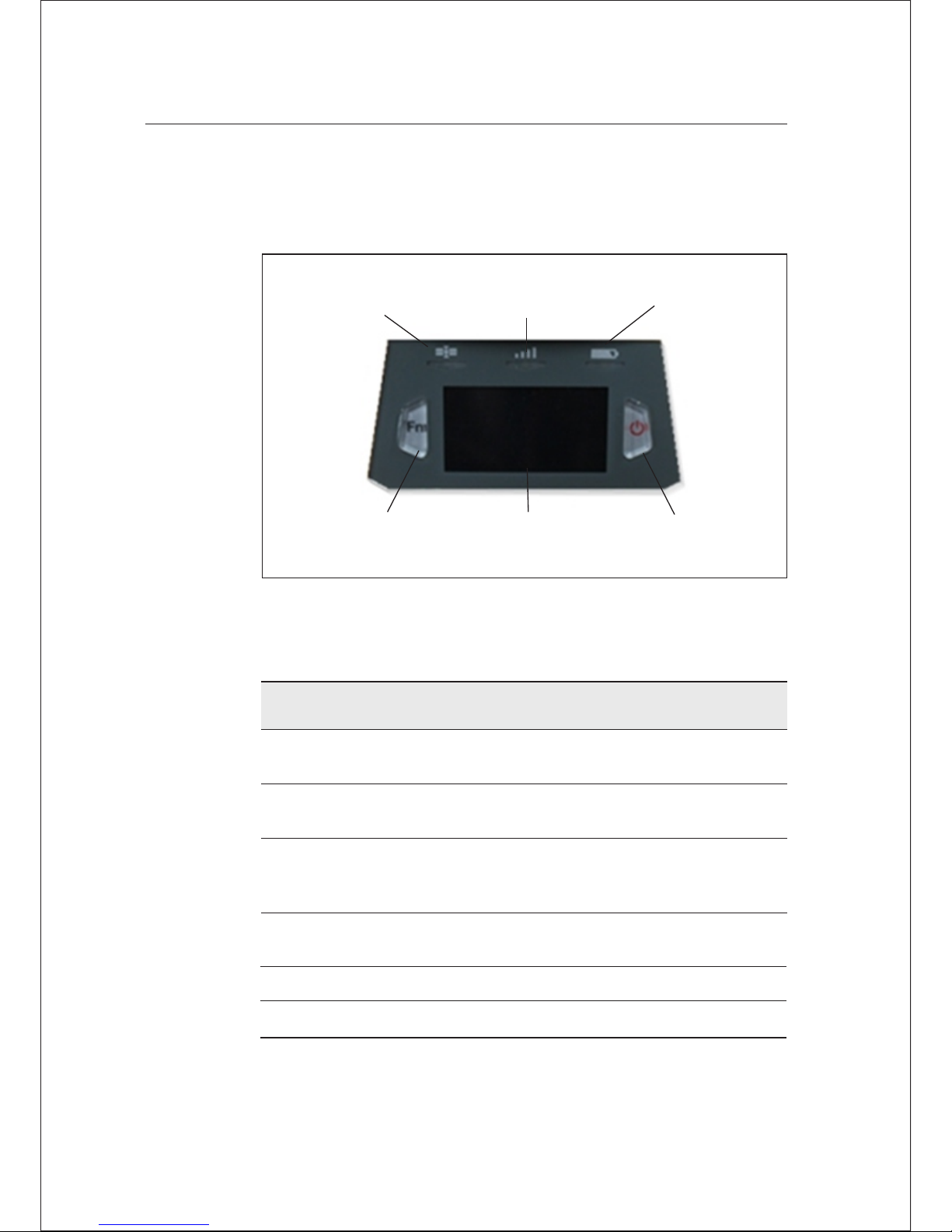
Control Panel
Most settings and operations of receiver are completed using two
keys on control panel.
Power
key
Satellite
light
Status
light
Power
light
Function
Key Fn
LCD
Display
The key operation shall be more than 3
seconds and less than 6 seconds, upo n the
sound of “ding-dong”
Table 3.2 Description of keys operat ion time
Figure 3-4
Operation name Note
Click action The key operation shall be less than 0.5
seconds
The interval between double clic k shall be less
than 1 second and more than 0.2 second s
Double-click
action
Long-press
operation
Super long-press
operation
The key operation shall be more than 6
seconds, upon two counts of “ding- dong”
Slow flashing
Light on greater than 0.5 seconds
Quick flashing
Light on less than 0.3 seconds
3 Elementary Operation
18 Hi-Target V60 GNSS RTK Receiver User Guide
Page 23
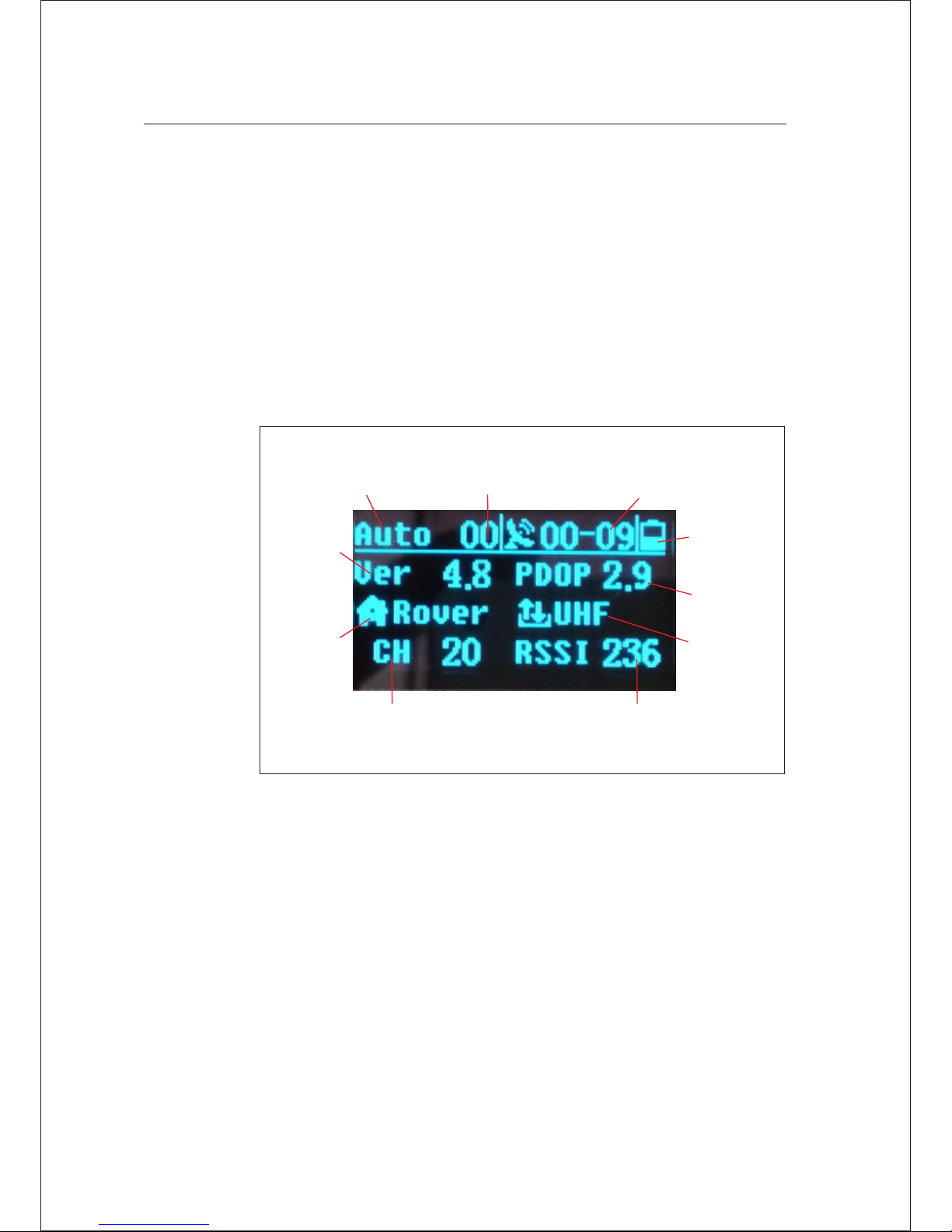
V60 GNSS RTK system can on or off LCD panel display through double
clicking power key. High-definition LCD panel can complete the basic
requirements of receiver with two keys, which also can flexibly set three
work modes, base, rover and static mode. The key operation of control
panel is specified as follows:
Key Functions
LCD coordinates key operation
Signal
enhancement value
Solution
state
Difference
age
Shared Satellites
- Visible Sat ellites
Host
firmware
version:
Working
mode
Radio
channel
Remaining
power of
host
PDOP
value
Data
link form
Figure 3-5
Double click the power key and start the LCD; the initial interface will
display current work mode and relevant basic information.
Hi-Target V60 GNSS RTK Receiver User Guide 19
Elementary Operation 3
Page 24
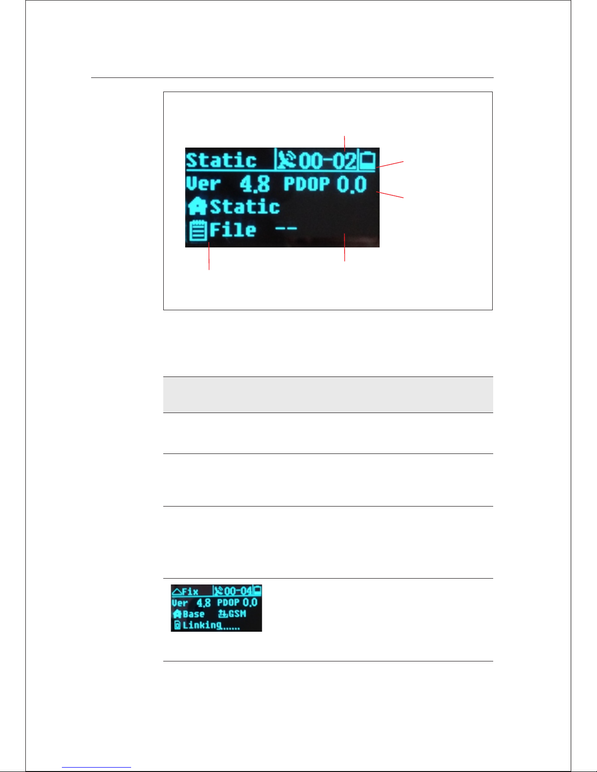
File name
of static data
Visible
satellite
Remaining
power of host
PDOP
value
Working
mode
Figure 3-6
Table 3.3 Description of key operati on (LCD state)
Function Operation Keys Conten t
On / Off LCD screen Double click
power key
Click Fn key and the
choice box is skipped
to next option
Confirm choice Click power key
option
Click power key; confirm
the contents inmenu
including choicebox;
enter into lower menu
Display / close
initial interface
Double click
power key
Display work mode of
receiver, satellite
information and version
information
20 Hi-Target V60 GNSS RTK Receiver User Guide
3 Elementary Operation
Selection menu Click Fn key
Page 25
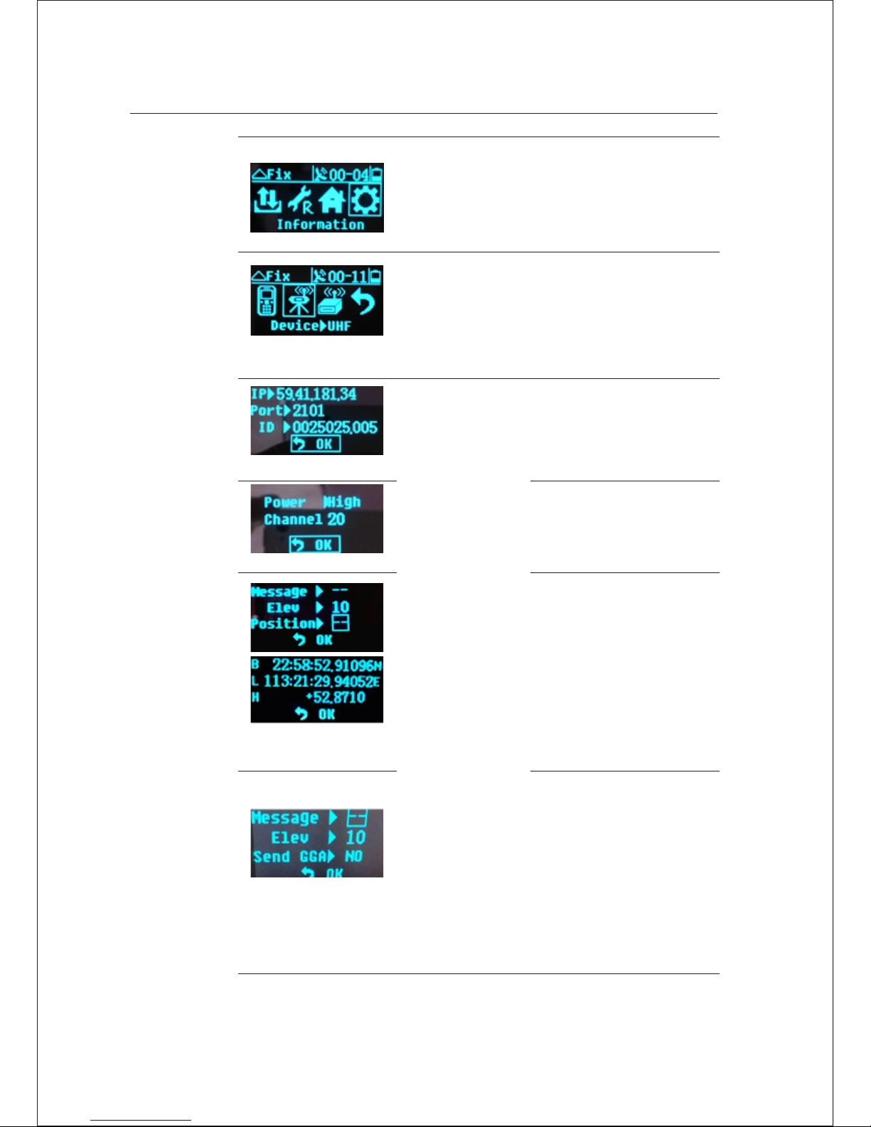
Click Fn key
PTK mode is indicated
as from left to right:
Data link; difference
parameters; work mode;
system information
Click Fn key and
skip choice box;
click power key
toconfirm the
choice
Data link menu contains
three optional data
chain models: GSM,
UHF (built-in), plug-in
and returning to
previous menu options
Switch data chain
GSM Parameter set:
Click Fn key and
skip choice box;
click power key
and enter into
edit state
After finishing
edit, click Fn key
choice box and
skip to “ok”; click
power key to
return to
previous menu
GSM data link: import IP
of server; port; group
No.; team No.
UHF Parameter set:
UHF (built-in): it can
choose low, middle and
high power and channel
0-115
Differential parameter
setting in base
The setting of
differenc e parameters
in base contains:
1. Differen ce massage
format: CMR/RTCM2
/RTCM3/sC MRx
2. Elevation angle:
0°-30°
3. Known points: B L H
Parameter setting
of rover
The setting of difference
parameters in rover
contains:
1. Difference massage
format: any forms autoadapted to base.
2. Elevation angle: 0°-30°
3. Frequency of
transmitting GGA data:
0s, 1s, 2s, 5s, 10s, 30s,
60s
Hi-Target V60 GNSS RTK Receiver User Guide 21
Elementary Operation 3
Page 26
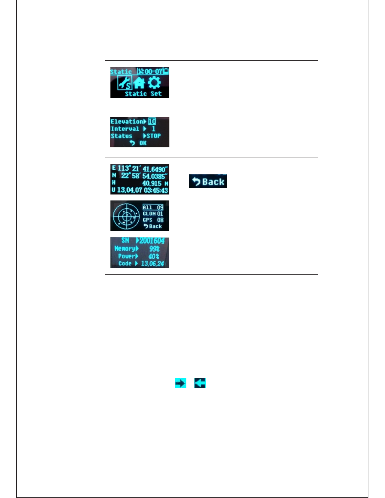
Static mode is indicated
as from left to right:
Static parameter; work
mode; system
information
Static parameter setting
Elevation angle 0 ° - 30 °
Sampling interval: 1s,
2s, 5s, 10s, 15s, 30s
1. Choose
click power key
to return to
previous menu;
2. If the interface
has no returning
option, click
power key to
return to
previous menu;
System information
provides the current
coordinates of receiver,
sky plot and system
state for users to inquire.
Taking edit height as an example, liquid crystal interface parameters are
edited from left to right. It will pop up a digital option box for selecting
operation.
Parameter editing method
2. If it is unnecessary to edit from the first bit, open the option box to
pitch on the cursor or , the cursor will skip one bit upwards
or downwards.
,
1. Firstly, the cursor is shown in underline quick flashing state at tens
digit. Click Fn key to choose figures; click power key after
confirming; the cursor will be automatically kipped to next bit.
22 Hi-Target V60 GNSS RTK Receiver User Guide
3 Elementary Operation
Page 27
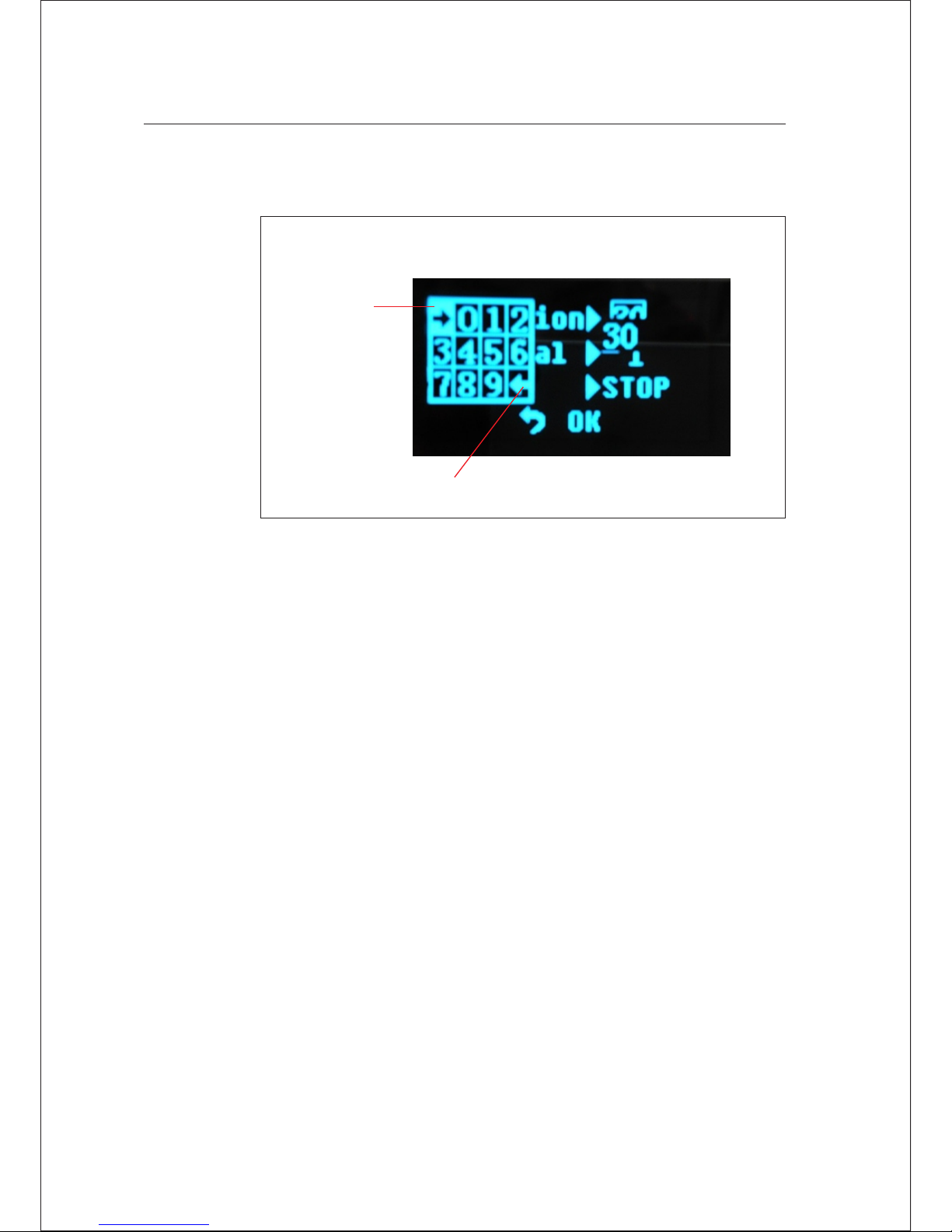
3. After editing, click Fn key, pitch on the frame and skip to next edit
option (such as sample interval).
Cursor skips
one place
downwards
Cursor skips one place upwards
Figure 3-7
No tes:
1. Only when liquid crystal displays initial interface or state
information, can the equipment terminal software be connected with
host through serial port/Bluetooth. When liquid crystal interface is
in mode parameter setting interface, the terminal is unable to
connect with the host. It is necessary to wait for liquid crystal
operation and return to previous menu.
2. As for GSM data link parameter setting interface, the panel can be
effective only setting Hi-Target server IP: 202.96.185.34, port:
9000, group number (7 bits), team number (3 bits); if connected by
CORS, parameter setting shall be operated through Hi-Target
handbook software.
3. During the process of static data collection, it is effective to set
parameters (elevation angle, sampling interval). The successful
parameters will be effective upon restarting static collection.
Hi-Target V60 GNSS RTK Receiver User Guide 23
Elementary Operation 3
Page 28
4. If the keys are not operated exceeding 50 seconds under LCD state,
the LCD will close automatically and the system will enter into key
mode, in order to economize power consumption. The user can
double click power key to restart LCD.
Use keys to off LCD
Table 3.4 Description of key operati on (without LCD state)
Function
Operation
keys
Content
Working
mode
Double
click Fn key
(interval
>0.2S; less
than 1S
Choose the work mode of “base”, “rov er”
and “static”.
Data link L ong-press
Fn key
(Greater
than 3 S)
Enter into the mode choice of “GSM”,
“UHF” and data link; click power key t o
pitch on the mode
UHF
mode
Click Fn key
Enter into “UHF radio channel” set ting
There are optional 116 channels from
0-115; when th e number of channels
exceeds 15, it is suggested to use liq uid
crystal and software setting for fastness
and convenience.
Click Fn key
and longpress Fn key
Add 10 to each channel
Setting
confir
mation
Click
power key
Promote current work mode, data li nk
mode, radio power and channel with
voice; use power lamp to indicate
electric quantity of battery
If there is no LCD, it can switch the work mode through two keys and
provide voice service to assist the users in finishing operation.
24 Hi-Target V60 GNSS RTK Receiver User Guide
3 Elementary Operation
Page 29

Automatic
set-up
base
Fn key +
power button
startup
Press on Fn key and then press power key
to start; loosen Fn key upon the sound o f
“ding dong”. Confirm the current s tate of
receiver with voice prompt
Reset
receiver
Super long
Fn key press
Reset motherboard If the handbook
Bluetooth fails to connect with the host
after resetting the host, it can adjust the
host in static mode and then reset after
data collection.
Table 3.5 Description of display sta te of indicator
under startup and shutdown mode
Start and Stop Receiver
Bootstrap
Press the
power button
for 1 second
All indicator
lights on
Shutdown
Starting music, work mode
before previous startup and
Voice prompt of data link
mode
Long press
power
button for
3 seconds
All indicator
lights off
Shutdown music
The display state of indicator under different setting modes is different.
See appendix 3: description of indicators on control panel.
SIM card/USIM Card
The receiver uses online data link mode to operate RTK; it is necessary to
prepare online communication card and open the relevant data
communication business. The card quantity demanded is set according to
the configuration of RTK measurement system. Each host and controller
installs one card. The receiver supports SIM card and USIM card.
Hi-Target V60 GNSS RTK Receiver User Guide 25
Elementary Operation 3
Page 30
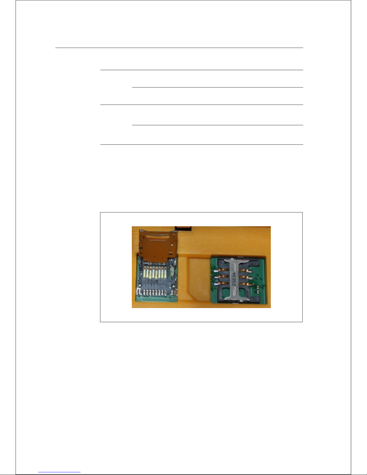
Table 3.6 Description of SIM card / USIM c ard
USIM
card
GPRS(ZHD/VRS)
SIM
card
GPRS(ZHD/VRS)
GSM
GSM
Before using SIM card or USIM card, please ensure GPRS data business
has been opened.
SIM installation procedure
1. Dismantle battery cover plate;take down the battery and disclose
SIM card slot.
Figure 3-8
26 Hi-Target V60 GNSS RTK Receiver User Guide
3 Elementary Operation
Page 31
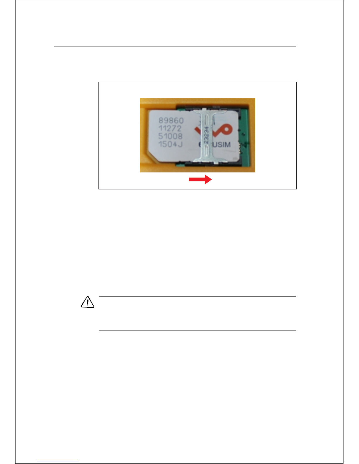
2. Place SIM card into cassette; insert the card into slot with front
down (the face with mental contacts) and lock the card
Figure 3-9
Radio
Radio frequency setting
The receiver shall apply an internal transceiver unit, whose centre
frequency is 460MHz. it can provide 116 communication channels to
users for selection and use. The user can choose channel on control
panel of receiver or use handbook software to set the channel.
Note-in case of modifications in transmit radio channel of base, the
rover shall also be modified to the sa me channel, or it will unable to
receive difference signals. It can only work normally in the sam e
channel.
Hi-Target V60 GNSS RTK Receiver User Guide 27
Elementary Operation 3
Page 32
Static Data Storage
Dual format storage for static data
It can use Hi-Target RTK software to start or close static data collection
function under standard form in GPS information advanced
settings RTK setting; it shall open or close static data collection
function under standard form before recording static collection; if it is
necessary the carry out the operation during collection process, the
collection will continue to record new file after stopping records. At this
time, the static data have been stored in two files.
Note-when the storage space o f receiver is less than 2M bytes,
the data light (red light) will flas h quickly and stop recording data.
The current data file will not be cove red.
Save data in internal storage
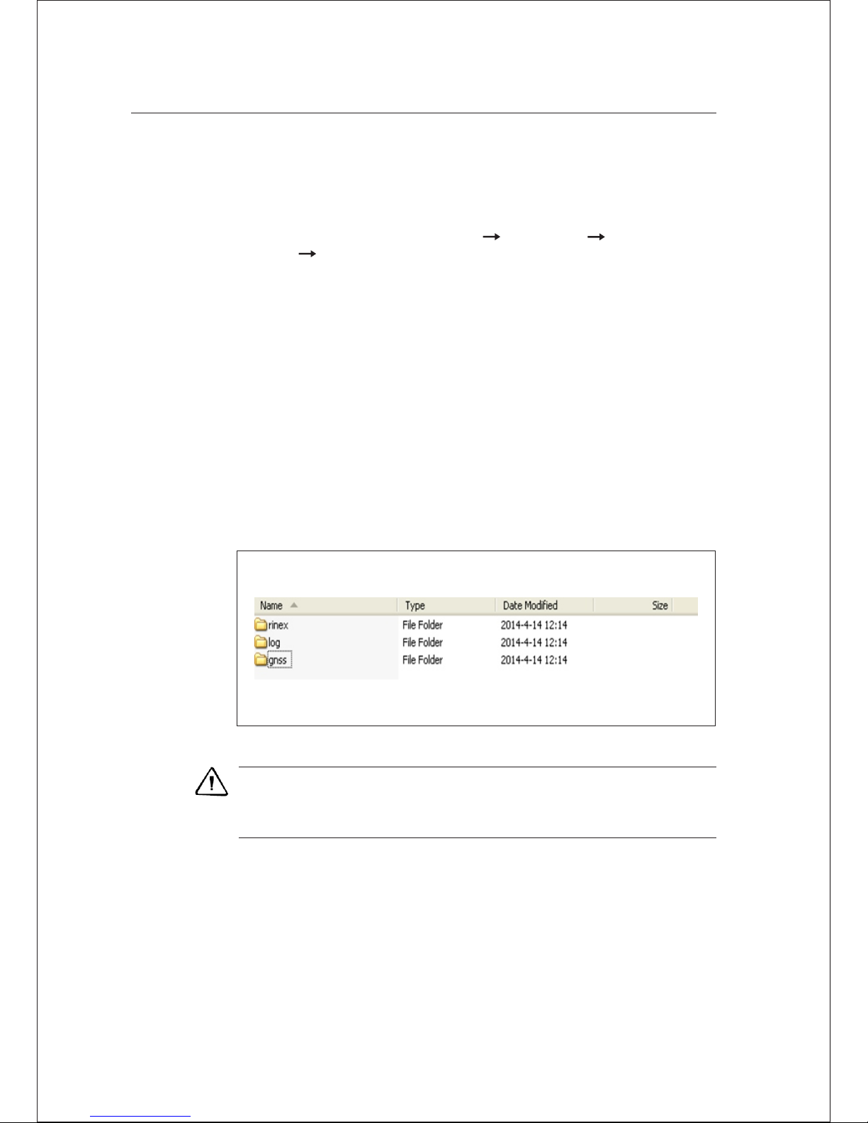
GNSS static data are stored in “static”: in 1G massive memory. The
effective storage space is 800M bytes. There are 3 files in total: log,
gnss, rinex. log folder stores log information; gnss folder stores static
data file whose format is *. GNS, rinex folder stores static data under
standard format. You can use USB of Y –type data line to connect with
the computer. Use USB to cop y the static data to your computer.
3 Elementary Operation
28 Hi-Target V60 GNSS RTK Receiver User Guide
Page 33
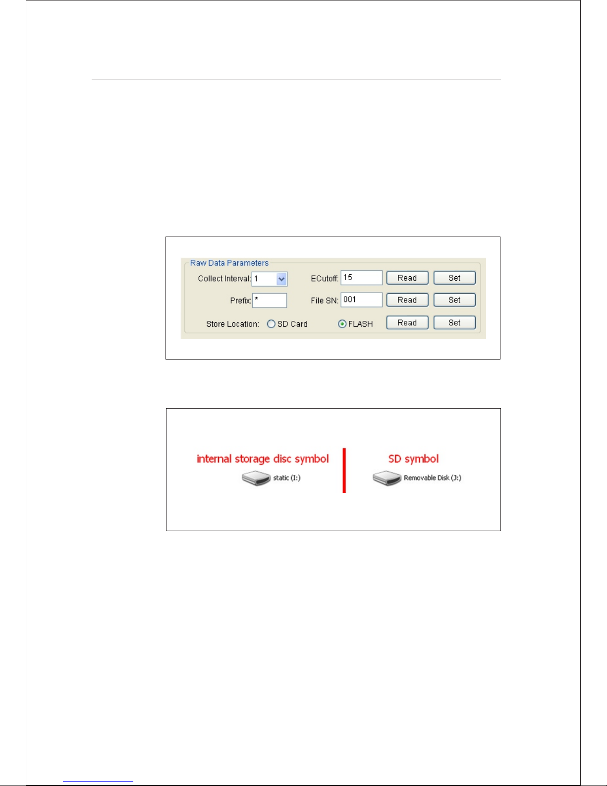
External SD card data storage
The receiver shall support SD card data. SD card slot is installed under
the battery. When the capacity of internal storage is not enough, the
system will automatically store the static data into SD card.
Before external data collection, it can use Y-type data line to connect the
computer and receiver. Through receiver management software,
manually set the storage location of static file in SD card/internal
memory. The setting is successful after restarting the instrument.
Figure 3-11
Figure 3-12
Elementary Operation 3
Hi-Target V60 GNSS RTK Receiver User Guide 29
Page 34
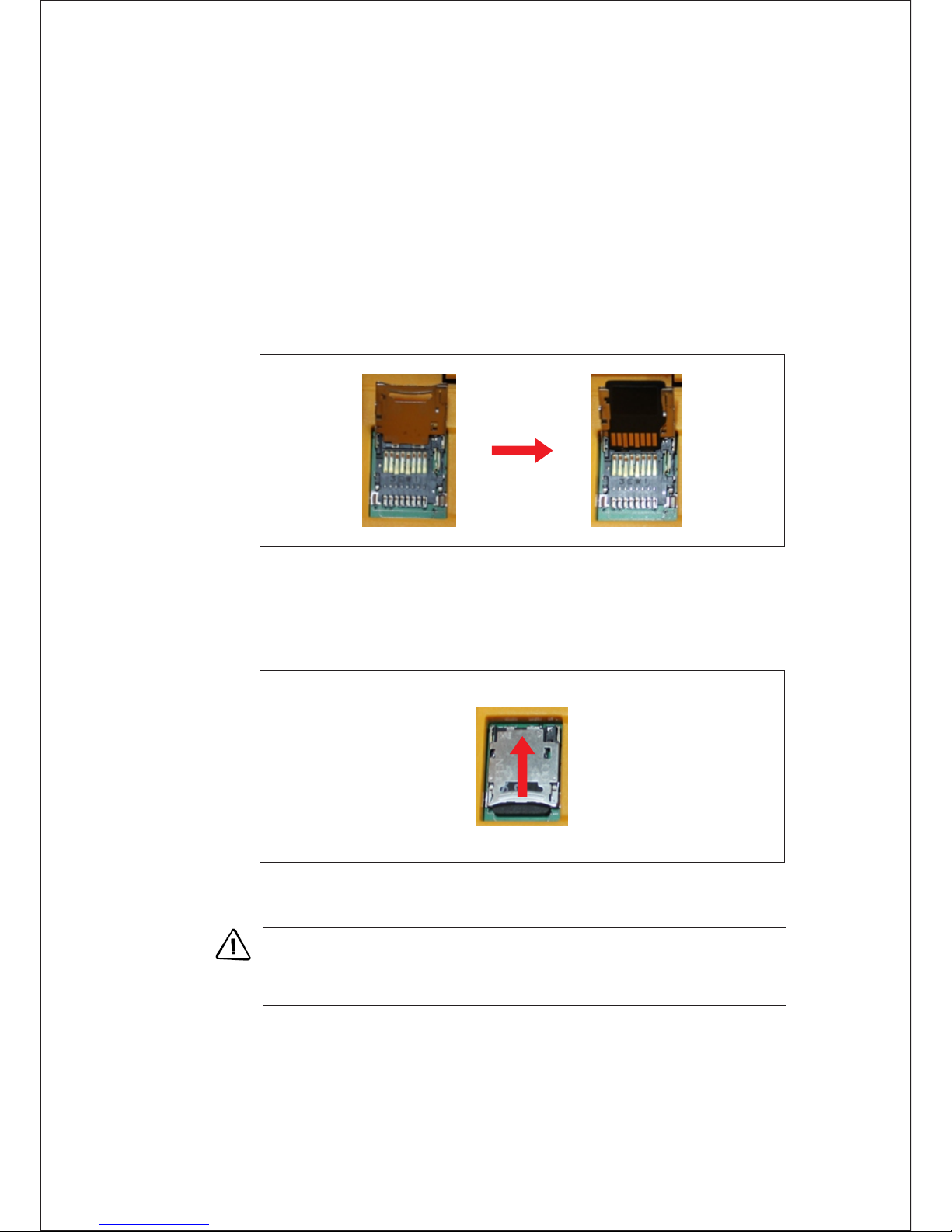
SD card
SD card installation procedure
1. Dismantle battery cover plate; take down the battery and disclose
SD card slot.
Figure 3-13
3. Push down the upper cover and push outside to fasten the upper
cover.
Figure 3-14
Warni ng-it shall turn off the power of receiver b efore installing
card. If SIM card is installed under s tartup state, the receiver will fail
to detect SIM card, and the setting of work mode will be ineffective.
2. Push up the mental cover according to the prompts; open the upper
cover of SD card and place SD card.
3 Elementary Operation
30 Hi-Target V60 GNSS RTK Receiver User Guide
Page 35
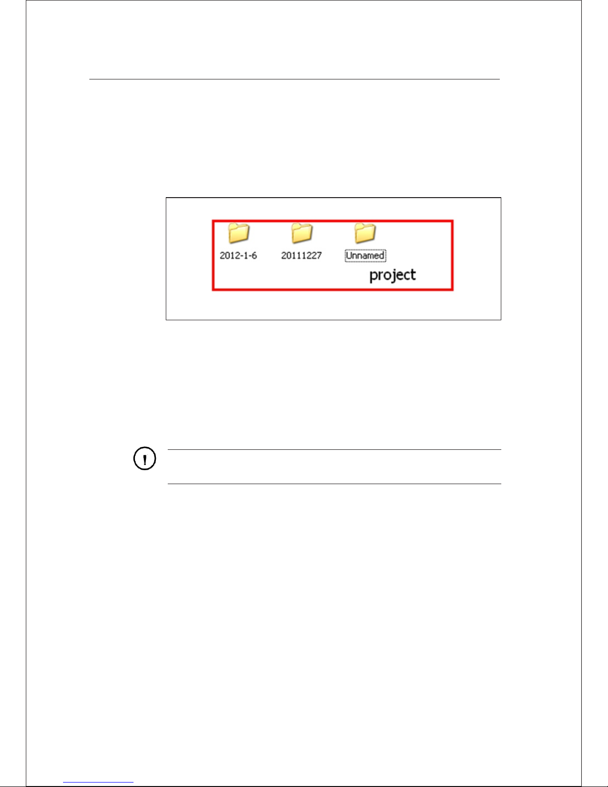
RTK Data storage
The controller can be connected with the receiver through Bluetooth.
After finishing setting, the collected RTK data will be store in
NandFlash of the controller. You can download RTK data to your
computer through the cable.
Figure 3-15
Reset receiver
Super long-press Fn key and reset the motherboard. The motherboard
can be recovered to delivery state.
Warni ng-the reset of motherboard will prolong the first locking
time of receiver. It is necessary to re set the work mode of receiver.
Formatting Receiver
If it is necessary to format the receiver, use the serial port of Y-type data
line to connect with the computer; open GNSS receiver management
software, choose serial port and open serial port. After connecting the
instrument, the upper side of management software will display the
machine number. Click “Format/Delete all” to format the receiver. All
data will be deleted and unable to recover.
Elementary Operation 3
Hi-Target V60 GNSS RTK Receiver User Guide 31
Page 36
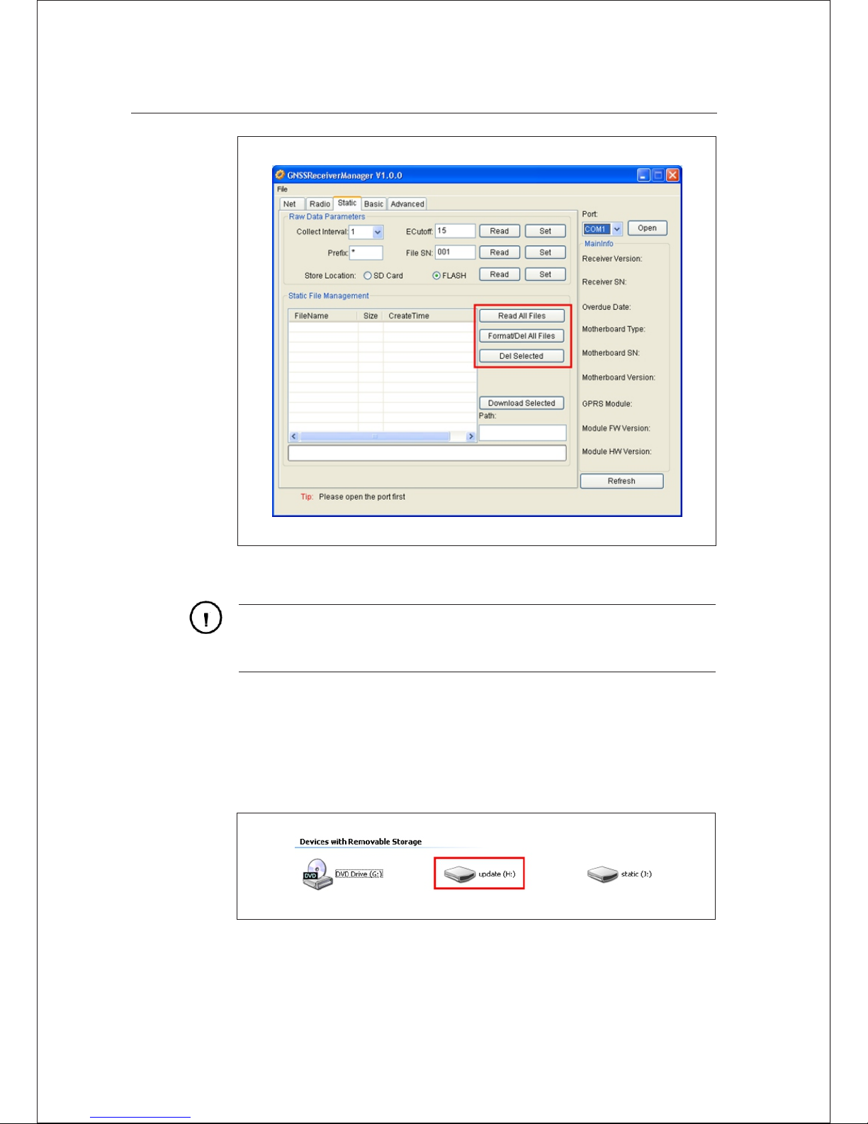
Figure 3-16
Warni ng-Before formatting the receiver, it shall ensure all useful
data in receiver are copied to the com puter. The data will not be
recovered upon deletion or forma tting.
The receiver can upgrade firmware through USB drive.
Upgrade steps of firmware:
Firmware
Figure 3-17
3 Elementary Operation
32 Hi-Target V60 GNSS RTK Receiver User Guide
Page 37

1. Firstly, it shall open the receiver and use Y-type data line to
connect with USB port of computer. Open “my computer”, and
“update” disk will appear.
2. Copy the firmware (the firmware can be downloaded from official
website) to “update” disk; remove U disk, pull up Y line and restart
the receiver.
3. During restarting process, it will have voice prompts in case of
failure or success. In case of failure in updating, please update
again or contact with technicians.
Hi-Target V60 GNSS RTK Receiver User Guide 33
Elementary Operation 3
Page 38

C H A P T E R
4
This chapter describes:
Preface
Static measurement
U disk data download
Operations of static management software
■
■
■
■
Static Collection and
Data Transmission
34 Hi-Target V60 GNSS RTK Receiver User Guide
Page 39

V60 receiver can be used in double-frequency static measurement. The
setting method is double clicking Fn key, and then the voice broadcast
will enter into work mode. Continue clicking Fn key and the work mode
of voice broadcast is static mode when the satellite light and state light
are on. Click power key to confirm. After successful setting, the red
state light will flash one by several seconds (according to the sampling
interval), one epoch will be collected by one flash. The static data can be
stored in host or SD card. If the static data document shall be
downloaded to computer, it shall use static post-processing software to
process.
1. Setup the instrument in measurement point; align and level the
instrument.
2. Measure height of the instrument for three times; the difference
between two times shall not be more than 3mm; the average is
regarded as the final height of instrument. Height of instrument
refers to the distance between center of measurement point and
measurement marker line of instrument.
3. Receiver parameters:
Preface
Static Measurement
Receiver radius 91mm
The height from receiver bottom to phase center of antenna is
94.2mm
The height from measurement line of instrument to phase center of
antenna is 39.3mm
■
■
■
Hi-Target V60 GNSS RTK Receiver User Guide 35
Static Collection and Data Transm ission 4
Page 40
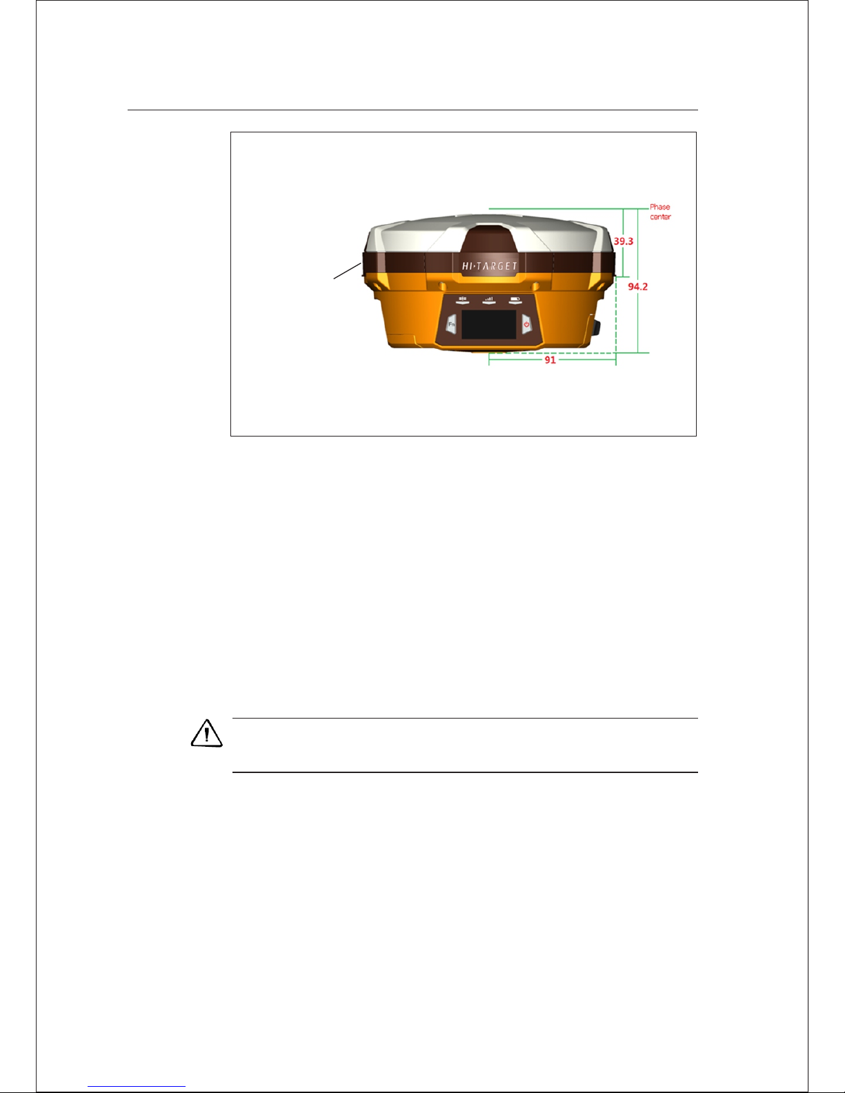
Measuring
position of
antenna height
(lower edge of
embossing
position)
Figure 4-1
4. Record the point name, instrument SN, height and initial
observation time.
Note-it is unable to move the base and change collection
parameters duringcollectio n process.
5. Start up and set the receiver as static mode. Flashing satellite light
indicates that it is searching the satellite. If the satellite light turns to
long-light state from flashing state, it indicates that the satellite is
locked. The state light will be flashing according to sampling interval.
One time of flashing indicates one epoch is collected.
6. Shut down after finishing measurement and record shutdown time.
7. Download and process data.
36 Hi-Target V60 GNSS RTK Receiver User Guide
4 Static Collection and Data Transm ission
Page 41
U Disk Data Download
Receiver file management is stored by USB drive. It can be used upon
inserting and download by dragging directly without download programs.
It can only download static data and unable to write or read the receiver.
The receiver can download USB drive data with Y-type data cable, one end
is connected to computer USB and the other end is connected to eight-core
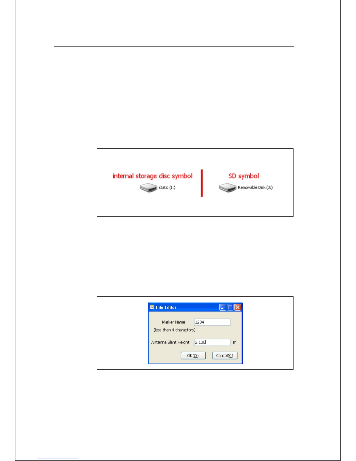
socket on bottom of receiver. After connection, “static” disk and SD card
will appear in computer. After opening the disk, it can copy the collected
static file.
Figure 4-2
The steps to modify point name and antenna height of downloaded
static file are:
1. Choose *. GNS and double click the mouse .
2. Pop up the dialogue of “file edit” to modify point name and input
antenna height, and then click “ok”.
Figure 4-3
Hi-Target V60 GNSS RTK Receiver User Guide 37
Static Collection and Data Transm ission 4
Page 42
Note-the static files in removable disk can be deleted by GNSS
receiver management software r ather than deleting directly.
Operations of Static Management Software
The main functio ns of GNSS receiver management software:
Delete the original data document
Delete and format the whole internal storage
Read and set the parameters
Set the storage path of static data
Procedures:
1. Use two ends of Y-type da ta line to connect eight-core socket of
receiver and serial port of computer.
2. Select computer port and click connect.
3. Refresh directory;the observed data file will appear in the form.
4. File name: 8 characters in total. The first character is replaced by
underline;the second, third and fourth character are the last three
characters of machine number;the fifth, sixth and seventh
character are annual day; the eighth character is the number of time
on that day.
5. Creation time: creation time of file (Beijing Time).
■
■
■
■
4 Static Collection and Data Transm ission
38 Hi-Target V60 GNSS RTK Receiver User Guide
Page 43
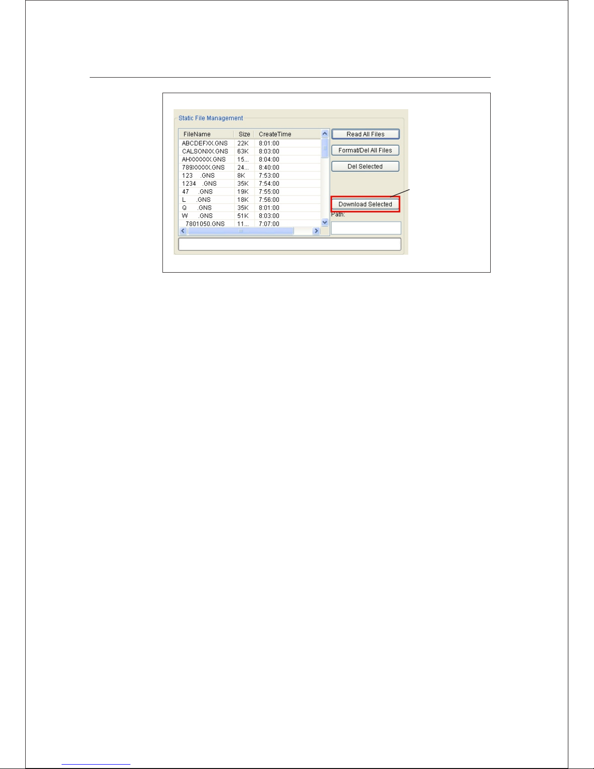
Figure 4-4
6. Deleting data: pitch on the data to delete, click and delete the
selected file.
7. Change collection interval and satellite cu toff angle: transmit the
data to change and click setting parameters Click and read the
parameters to investigate the original collection interval and
satellite cutoff angle.
8. Format data: click “Format/Delete all” to format the receiver. All
data will not be recovered after deleting.
Hi-Target V60 GNSS RTK Receiver User Guide 39
Static Collection and Data Transm ission 4
V60 does not
support serial
port download
Page 44

C H A P T E R
5
Technical Parameters
This chapter describes:
GNSS part
Receiver precision
UHF radio
Interface
Physical characteristics
Environment
■
■
■
■
■
■
40 Hi-Target V60 GNSS RTK Receiver User Guide
Page 45

Technical Parameters 5
GPS: synchronously track L1 C/A, L2E, L2C, L5
BDS: synchronously track B1, B2
GLONASS: synch ronously track L1 C/A, L1 P, L2 C/A (only
limited to GLONASS M) and L2P
SBAS, WASS, MSAS, ENGOS
GALILEO:( upgrade reserved)
Initial time is less than 10 seconds
Initial reliability: >99.9%
1Hz, 2Hz, 5Hz, 10Hz, 20Hz and 50Hz navigation output
Difference format supports: sCMRx, CMR, CMR+, RTCM 2.1, 2.2,
2.3, 3.0, 3.1, 3.2
Navigation output format: ASCII: NMEA-0183 GSV, AVR, RMC,
HDT, VGK, VHD, ROT, GGK, GGA, GSA, ZDA, VTG, GST, PJT,
PJK, BPQ, GLL, GRS , GBS
Accuracy of static mode and fast static mode:
Vertical: ± (5+0.5×10⁻⁶D) mm
Receiver Precision
GNSS Part
UHF Radio
It is compatible to the current radio received or transmitted by
460MHz
With difference receiving and transmission function. The
transmission power can be adjusted in 1W, 2W and 5w.
116 channels can be exchanged flexibly
It defaults 9.6Kbps wireless transmission rate. The maximum
wireless transmission rate is 19.2Kbps
■
■
■
■
■
■
■
■
■
■
■
■
■
■
■
■
Hi-Target V60 GNSS RTK Receiver User Guide 41
Horizontal:±(2.5+0.5×10⁻⁶D) mm
RTK navigation accuracy: Horizontal: ±(8+1×10⁻⁶D) mm
Vertical: ± (15+1×10⁻⁶D) mm
Page 46

Two RS232 serial interfaces
One USB interface
1 SIM card interface
1 SD card interface
1 UHF antenna interface
1 Bluetooth interface
1 built-in lithium battery interface
Two external DC p ower input interface
Physical characteristics
Interface
Built-in 1GB memory
Volume: φ182mm×h98mm
Weight: 1.25kg (excluding lithium battery)
It can resist 2m natural falling and 2m underwater soaking
5000 mAh large-capacity lithium battery is installed internally for
power supply The continuous working hours of new battery: 12
hours in static; 9 hours in GPRS mode; 7 hours for 2W radio
transmission
External DC power supply; input range of width is 6-28V;internal
and external power supply can switch automatically
Host power consumption (under static mode): ≤3.5W
Protection grade: Ip67
Working temperature: -40℃- 65℃;storage
temperature:-40℃ -75℃
Environment
■
■
■
■
■
■
■
■
■
■
■
■
■
■
■
■
■
42 Hi-Target V60 GNSS RTK Receiver User Guide
5 Technical Parameters
Page 47

C H A P T E R
6
This chapter describes:
Preface
Difference antenna
Y-type data cable
DDTHPB external radio
■
■
■
■
Socket and Main
Accessories
Hi-Target V60 GNSS RTK Receiver User Guide 43
Page 48
Preface
The chapter will introduce the appearance and application of main
interface of receiver and accessories. The following equipment does not
represent all users purchased V60. According to different
configurations, the specific configuration shall be subject to the
delivery order upon purchasing.
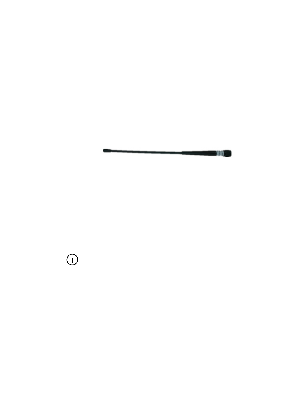
Difference Antenna
Figure 6-1
UHF base mode and UHF rover mode shall use difference antenna. The
difference antenna of UHF base mode is us ed to transmit UHF
difference signal. The difference antenna of UHF rover mode is used to
receive UHF difference signal.
Difference antenna installation:
Grasp the fixed nut in bottom of different antenna with hand to install
clockwise. On the contrary, dismantle difference antenna anticlockwise.
Warni ng-when installing difference antenna, it shall rotate the
fixed nut in bottom of difference antenna with hand rather that
grasping the upper side of difference antenna, or it will break off the
differenc e antenna.
44 Hi-Target V60 GNSS RTK Receiver User Guide
6 Socket and Main Acces sories
Page 49
Socket and Main Acces sories 6
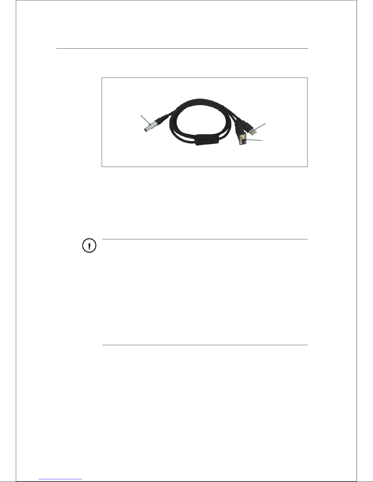
Y-type Data Cable
Eight-core plug: connect eight-core socket of receiver
USB interface: connect computer USB interface and download the static
data of receiver.
Serial interface: it is used to connect with computer serial port, update
receiver firmware, set the receiver, manage static data and set the radio.
USB
Port
Eight-core
plug
Series
interface
Figure 6-2
Warning:
1. when connecting various plugs o f receiver, it shall align the
redpoint in line joint at the red poin t in receiver socket, or it
will damage the receiver socket an d plugs of various lines.
DDTHPB External Radio
DDTHPB external radio is a type of radio improving the performance of
relay radio UH-3000. DDTHPB radio has all functions of URS relay
radio. Compared to other radios, it is also functional in power
transposition protection. Even though the external power is connected
wrongly, DDTHPB radio will not be burn out.
2. When plug out the plug, directly gr asp the sliding collar and
pull out the plug with effort. I t shall not rotate the plug.
3. After using the cable, it shall plac e the cable in the place
difficult for extrusion, i n order to prevent damaging the plug.
When installing the differ ence antenna, it shall rotate the fixed
nut in bottom of difference an tenna with hand, rather than
grasping the upper side to rotate, or the difference antenna will
be in bad contact and influence the op erating range.
Hi-Target V60 GNSS RTK Receiver User Guide 45
Page 50
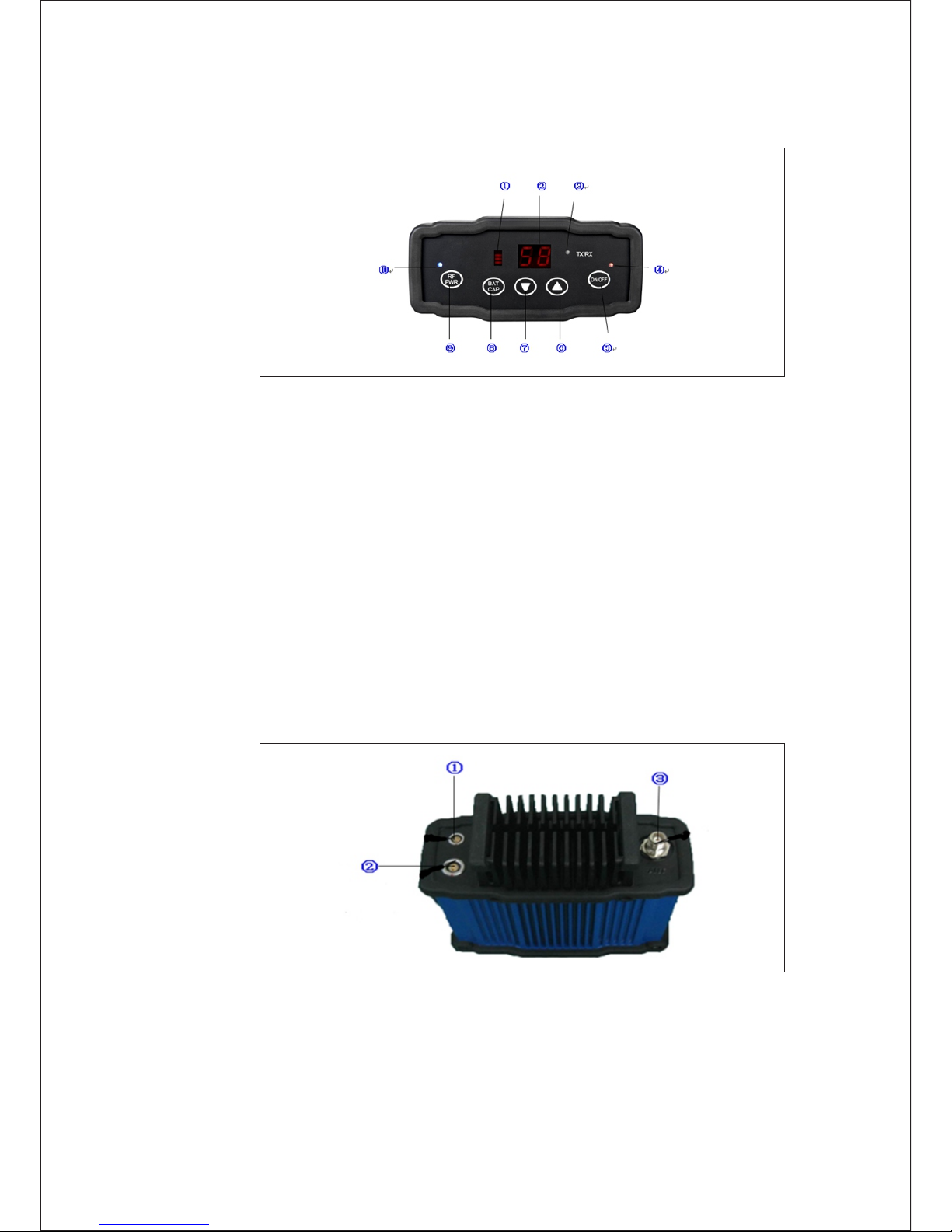
1. Field intensity/power voltage indicator D1
2. Dibit nixie tube indicator D2
3. Send-receive indicator light D3
4. Power/warning indicator D4
5. Key K4 (power on-off key)
6. Key K4 (channel increasing key)
7. Key K3 (channel decreasing key)
8. Key K2 (electric quantity checking key)
9. Key K1 (power toggle key)
10. Power indicator light D5
Figure 6-3
DDTHPB radio interface:
Figure 6-4
46 Hi-Target V60 GNSS RTK Receiver User Guide
6 Socket and Main Acces sories
Page 51

1. Base host to radio cable interface
2. External power interface
3. Transmitting antenna interface
As for the specific operations of DDTHPB external radio, please refer to
its manual.
Hi-Target V60 GNSS RTK Receiver User Guide 47
Socket and Main Acces sories 6
Page 52

Annexed Table 1 Defaulted Frequency
Table upon Delivery
The user may change defaulted frequency of 16 channels of the radio.
Table 1 Defaulted frequency table of 16 channels in radio
Channel
number
460M frequency
band (MHZ)
230M frequency
band (MHZ)
445M frequency
band (MHZ)
Receive send Receive Send Receive Se nd
1 00 45 9 . 3 25 45 9 . 225 2 3 0 . 725 2 3 0 .625 4 4 5 .12 5 4 4 5 .02 5
1 01 45 9 . 4 25 45 9 . 325 2 3 0 . 825 2 3 0 .725 4 4 5 .22 5 4 4 5 .12 5
1 02 45 9 . 5 25 45 9 . 425 2 3 0 . 925 2 3 0 .825 4 4 5 .32 5 4 4 5 .22 5
1 03 45 9 . 6 25 45 9 . 525 2 3 1 . 025 2 3 0 .925 4 4 5 .42 5 4 4 5 .32 5
1 04 45 9 . 7 25 45 9 . 625 2 3 1 . 125 2 3 1 .025 4 4 5 .52 5 4 4 5 .42 5
1 05 45 9 . 8 25 45 9 . 725 2 3 1 . 225 2 3 1 .125 4 4 5 .62 5 4 4 5 .52 5
1 06 45 9 . 9 25 45 9 . 825 2 3 1 . 325 2 3 1 .225 4 4 5 .72 5 4 4 5 .62 5
1 07 46 0 . 0 25 45 9 . 925 2 3 1 . 425 2 3 1 .325 4 4 5 .82 5 4 4 5 .72 5
1 08 46 0 . 1 25 46 0 . 025 2 3 1 . 525 2 3 1 .425 4 4 5 .92 5 4 4 5 .82 5
1 09 46 0 . 2 25 46 0 . 125 2 3 1 . 625 2 3 1 .525 4 4 6 .02 5 4 4 5 .92 5
1 10 46 0 . 3 25 46 0 . 225 2 3 1 . 725 2 3 1 .625 4 4 6 .12 5 4 4 6 .02 5
1 11 46 0 . 4 25 46 0 . 325 2 3 1 . 825 2 3 1 .725 4 4 6 .22 5 4 4 6 .12 5
1 12 46 0 . 5 25 46 0 . 425 2 3 1 . 925 2 3 1 .825 4 4 6 .32 5 4 4 6 .22 5
1 13 46 0 . 6 25 46 0 . 525 2 3 2 . 025 2 3 1 .925 4 4 6 .42 5 4 4 6 .32 5
1 14 46 0 . 7 25 46 0 . 625 2 3 2 . 125 2 3 2 .025 4 4 6 .52 5 4 4 6 .42 5
1 15 45 9 . 2 25 46 0 . 725 2 3 0 . 625 2 3 2 .125 4 4 5 .02 5 4 4 6 .52 5
6 Socket and Main Acces sories
48 Hi-Target V60 GNSS RTK Receiver User Guide
Page 53
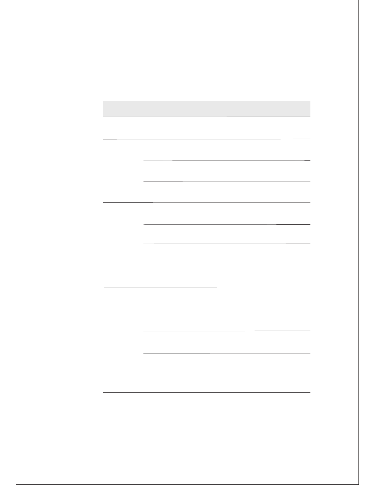
Annexed Table 2 Instructions of Indicator
Lights in Control Panel
Annexed Table 2.1 Instructions of indicator li ghts
Operation Signi fication
Power light
(Yellow)
AlwaysonNormal voltage: internal batte ry >7.6V;
external battery >12.6V
Power light
(Red)
Always
on
Slow
flashing
Quick
flashing
Normal voltage: 7.1V< internal
battery≤7.6V, 11V<external batter y≤12.6V
Under voltage: Internal batter y
≤7.1V; external battery ≤11V
Indicating electric quantity : flash 1-4 times
every minute; indicate electri cal quantity
Signal
lamp;
indicator
(Status
Green)
Always
off
GSM is not used
Always
on
GSM connection to server
Slow
flashing
It indicates that it has logged in
GPRS network upon GSM
Quick
flashing
It indicates that it is logging in
GPRS network upon GSM
Slow
flashing
1. data link receiving and transmi ssion
data (the rover is only for promotin g
receiving; the base is only for prom oting
the transmission)
2. Static data collection
Data light
(Status
Red)
Quick
flashing
1. error occurred upon static mode
(FLASH storage space is not enough )
Always
on
The data link equipment used in rove r or
base is unable to communicate. The
communication module is in failu re without
data output.
Socket and Main Acces sories 6
Hi-Target V60 GNSS RTK Receiver User Guide 49
Page 54
Satellite
light
(Green)
Always
on
Slow
flashing
Quick
flashing
Locked satellites
Satellite search or satellite lo sing lock
Report the number of satellite onc e every
minute upon locking the satellit e
Always
off
1. Upon resetting receiver, the mot herboard
is in failure without data output.
2. Under static mode, the motherbo ard
is in failure without data output.
The display status of indicator under different setting modes:
1. Work mode (double click Fn key to enter into the pattern of work
mode setting; choose the mode after clicking Fn key; press powerkey
to confirm; it will automatically confirm if the power key is not
pressed for exceeding 10 seconds;) ● on; ○ off
Annexed Table 2.2 Display status of indicator un der work mode
Mode
Satellite lamp
(single green)
Base ● ○
Rover ○ ●
Static ● ●
Signal light
(green light in double lights)
2. Data link (long press Fn key to enter into data link setting mode;
choose the mode after clicking Fn key; press power key to confirm;
it will automatically confirm if the power key is not pressed for
exceeding 10 seconds;) ● on ○ off
;
6 Socket and Main Acces sories
50 Hi-Target V60 GNSS RTK Receiver User Guide
Page 55

Annexed Table 2.3 Display status of indicator un der data chain mode
Type
Satellite lamp
(single green)
UHF
GSM
External
Signal light
(green light in double lights)
● ○
○ ●
● ●
Hi-Target V60 GNSS RTK Receiver User Guide 51
Socket and Main Acces sories 6
 Loading...