

Page 1
HD-MAX Echo Sounder User Guide
1
Foreword
Application of Manual
Welcome to use the Manual of HI-TARGET HD-MAX series products. This
Manual describes how to set up and use HD-MAX series products.
Introduction of the Manual
The Manual specifies related instructions on hardware and software of
HD-MAX series products. Please follow the contents of the Manual during
operation.
Experience Requirements
In order to better use HD-MAX series products, HI-TARGET suggests that
the operator shall have certain knowledge on measurement and shall read the
Manual carefully. For more information about the system, please visit the
official website of HI-TARGET: www.hi-target.com.cn/en
Security technology prompts
Attention: Special operation needs special attention. Please read the
contents carefully.
Warning: Very important prompts. Operations not following the
warning contents will cause instrument damage, data loss, system
collapse, and even will endanger personal safety.
Disclaimer
We have checked the contents of the current Rev. of Manual as well as the
consistency between the hardware and software, which doesn't means that the
possibility of deviation has been ruled out. Therefore, we do not guarantee
that the contents described in this Manual, the hardware and software are
Page 2

HD-MAX Echo Sounder User Guide
2
completely consistent. All the data indicated in the Manual have been
inspected. Necessary correction values are included in the following Rev.
Technology and services
For any questions encountered during the operation process, please contact
our technical personnel. We will promptly answer your questions.
Your suggestions
If you have any suggestions and opinions regarding this Manual, please
provide feedback to us. Your feedback can significantly improve the quality
of the Manual.
Page 3

HD-MAX Echo Sounder User Guide
3
CONTENTS
Overview........................................................................................................... 7
Navigation Overview..................................................................................8
Principle of Echo Sounder.......................................................................... 8
Product Features........................................................................................11
Technical Parameters................................................................................ 11
Hardware Introduction of HD-MAX ......................................................... 12
Front Face of the Host .............................................................................13
Back Face of the Host............................................................................... 14
Side Faces of the Host...............................................................................14
Other Accessories ....................................................................................15
Basic Operations............................................................................................ 20
Startup & Shutdown..................................................................................21
Buttons ....................................................................................................21
Interface at the backside............................................................................23
Software Introduction ..................................................................................26
Software Overview ................................................................................. 27
Technical Parameters................................................................................ 30
Installation of Software.............................................................................30
Simple Operation Process............................................................................. 37
Main Interface...........................................................................................38
Simple Operation Process.........................................................................38
Conclusion of This Chapter...................................................................... 41
Project Management......................................................................................42
Project Settings......................................................................................... 43
Page 4

HD-MAX Echo Sounder User Guide
4
Conclusion of This Chapter...................................................................... 44
Coordinate parameters ................................................................................45
Parameters Settings of Coordinate Transformation ................................ 46
Conclusion of This Chapter...................................................................... 56
Device Connection..........................................................................................57
GPS Settings............................................................................................. 58
Auxiliary Equipment Settings...................................................................63
Conclusion of This Chapter...................................................................... 65
Ship Design..................................................................................................... 66
Ship Design...............................................................................................67
Conclusion of This Chapter...................................................................... 68
Plan line design...............................................................................................69
Plan line preparation................................................................................. 70
Plan line edit............................................................................................. 72
Plan line routing........................................................................................ 75
Plan line import-export ........................................................................... 81
Shortcut key.............................................................................................. 81
Other functions..........................................................................................81
Conclusion of This Chapter...................................................................... 82
Electronic Chart............................................................................................. 83
Sea Chart Import....................................................................................... 84
Sea Chart Display..................................................................................... 87
Sea Chart Inquire...................................................................................... 89
Conclusion of This Chapter...................................................................... 89
Engineering Base Map...................................................................................91
Engineering Base Map Management........................................................ 92
Page 5

HD-MAX Echo Sounder User Guide
5
Engineering Base Map Display................................................................ 93
Conclusion of This Chapter...................................................................... 94
Depth Measurement.......................................................................................95
Common Functions Introduction.............................................................. 97
Parameters Setting.................................................................................. 107
Real-time Information Display............................................................... 111
Data Acquisition......................................................................................112
Data Playback......................................................................................... 114
Depth Measurement Setting....................................................................115
Conclusion of This Chapter.................................................................... 117
Sounding Sampling...................................................................................... 118
Basic Functions Introduction.................................................................. 120
Sounding Correction............................................................................... 121
Sounding Sampling.................................................................................122
Conclusion of This Chapter.................................................................... 124
Data Correction............................................................................................125
Introduction to this Chapter.................................................................... 125
Transformation Parameters Correction...................................................127
Delayed Correction ............................................................................... 127
Water Elevation Correction.....................................................................128
Draft Correction......................................................................................129
Conclusion of This Chapter.................................................................... 129
Tide Level Correction ................................................................................ 130
Introduction to this Chapter.................................................................... 130
Tide Station Data.................................................................................... 131
Regional Correction Settings.................................................................. 133
Data Correction.......................................................................................136
Conclusion of This Chapter.................................................................... 137
Achievements Preview.................................................................................138
Page 6

HD-MAX Echo Sounder User Guide
6
Data Preview...........................................................................................139
Data Output.............................................................................................140
Conclusion of This Chapter.................................................................... 140
Serial Port Debugging ................................................................................142
Satellites Information..............................................................................143
Data Debugging...................................................................................... 144
Base Setting............................................................................................ 148
Rover Setting.......................................................................................... 152
Conclusion of This Chapter.................................................................... 159
Utilities.......................................................................................................... 160
Coordinate Transformation Parameters Calculation...............................161
Coordinate Transformation..................................................................... 168
Distance Orientation Calculation............................................................ 168
Unit Conversion .................................................................................... 169
Coordinates library..................................................................................170
Conclusion of This Chapter.................................................................... 170
Software Registration ................................................................................ 171
Software Registration ............................................................................172
Software Dongle..................................................................................... 172
Conclusion of This Chapter.................................................................... 172
Software Upgrading..................................................................................... 173
Local Upgrading..................................................................................... 174
Online Upgrading....................................................................................175
Conclusion of This Chapter.................................................................... 177
Page 7

HD-MAX Echo Sounder User Guide
7
C H A P T E R
1
Overview
Introduction to this Chapter
■ Navigation Overview
■ Principle of Echo Sounder
■ Product Features
■ Technical Parameters
Page 8

HD-MAX Echo Sounder User Guide
8
Navigation Overview
Global Positioning System (GPS) has developed for many years. It has been
upgraded from stand-alone GPS accurate to 100m which can only be applied
for rough navigation and positioning to real-time differential GPS (DGPS)
accurate to several centimeters which can be applied in various measurement
fields. GPS technology has become increasingly mature, varieties of products
have been produced, and there are more and more users applying DGPS
technology.
As the world's most popular positioning method, DGPS has been widely
applied in marine sounding, waterway survey, engineering exploration
orientation, cadastral survey, terrain cadastral survey, boundary demarcation,
harbor piloting, navigation of geophysical prospecting and hydrocarbon
exploration and staking of seismic shot and other measurement fields. Thus,
a measuring software which can realize multiple functions is needed.
The software is compatible to a variety of import and domestic GPS receivers.
It is a measuring tool software integrating measurement, editing and other
multiple functions with task-based operating mode and fool operation
interface. Adhering to the purpose of high and new technology popularization
as well as plebification. The software will appreciate the users relying on
more economical price as well as intelligent operation.
Principle of Echo sounder
Echo sounding principle
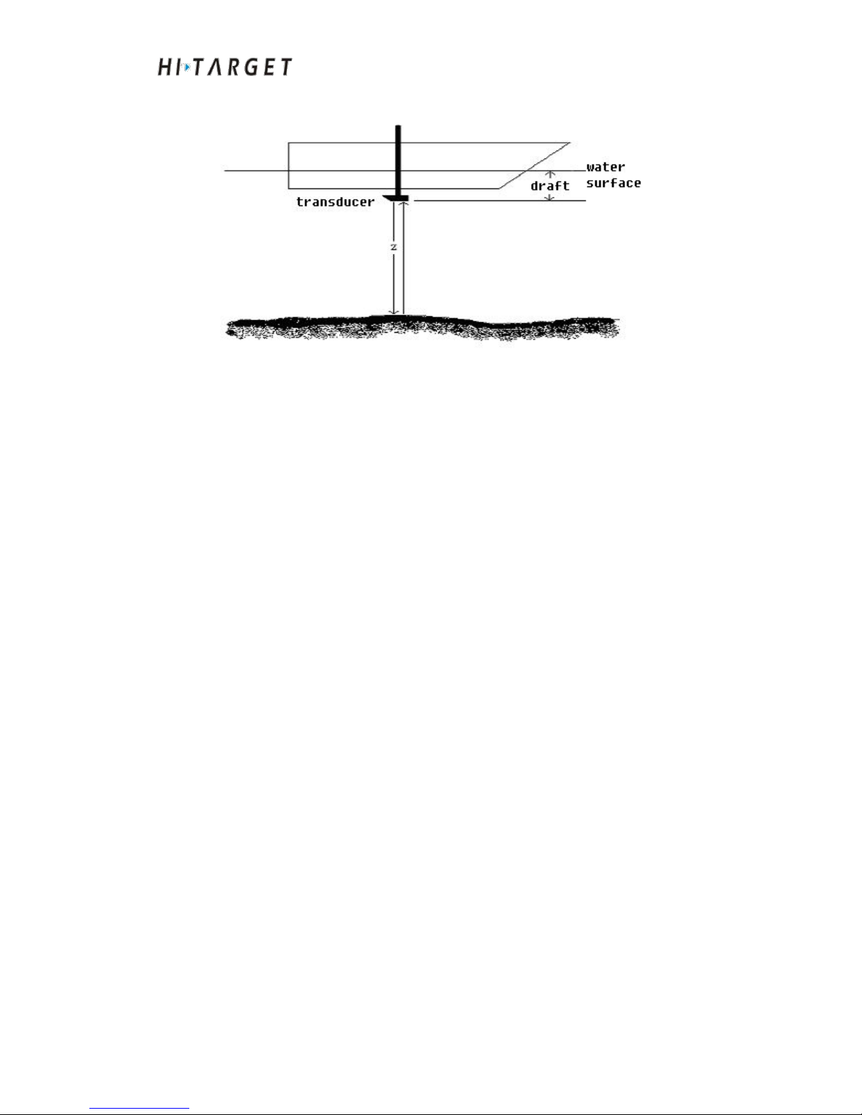
It is assumed that the sound speed under water is V. In case of a pulse
acoustic signal being loaded on a transducer, acoustic wave is transmitted
from the transducer to the seabed and then back. The time of acoustic signal
round trip is t, then:
Page 9
HD-MAX Echo Sounder User Guide
9
Z = V*t/2
Figure 1-1
Z is the depth from the transducer to the seabed, plus transducer draft.
Underwater signal recognition
Although the principle of depth sounding is simple, the situation in the water
is very complicated with parasitic echo, haunted by fish or clutter echo and
different reflection conditions at water bottom. In shoal waters, second trip
echo, triple transit echo may turn up. Relevant technology has to be adopted
on how to track the real underwater echo signal from numerous clutters.
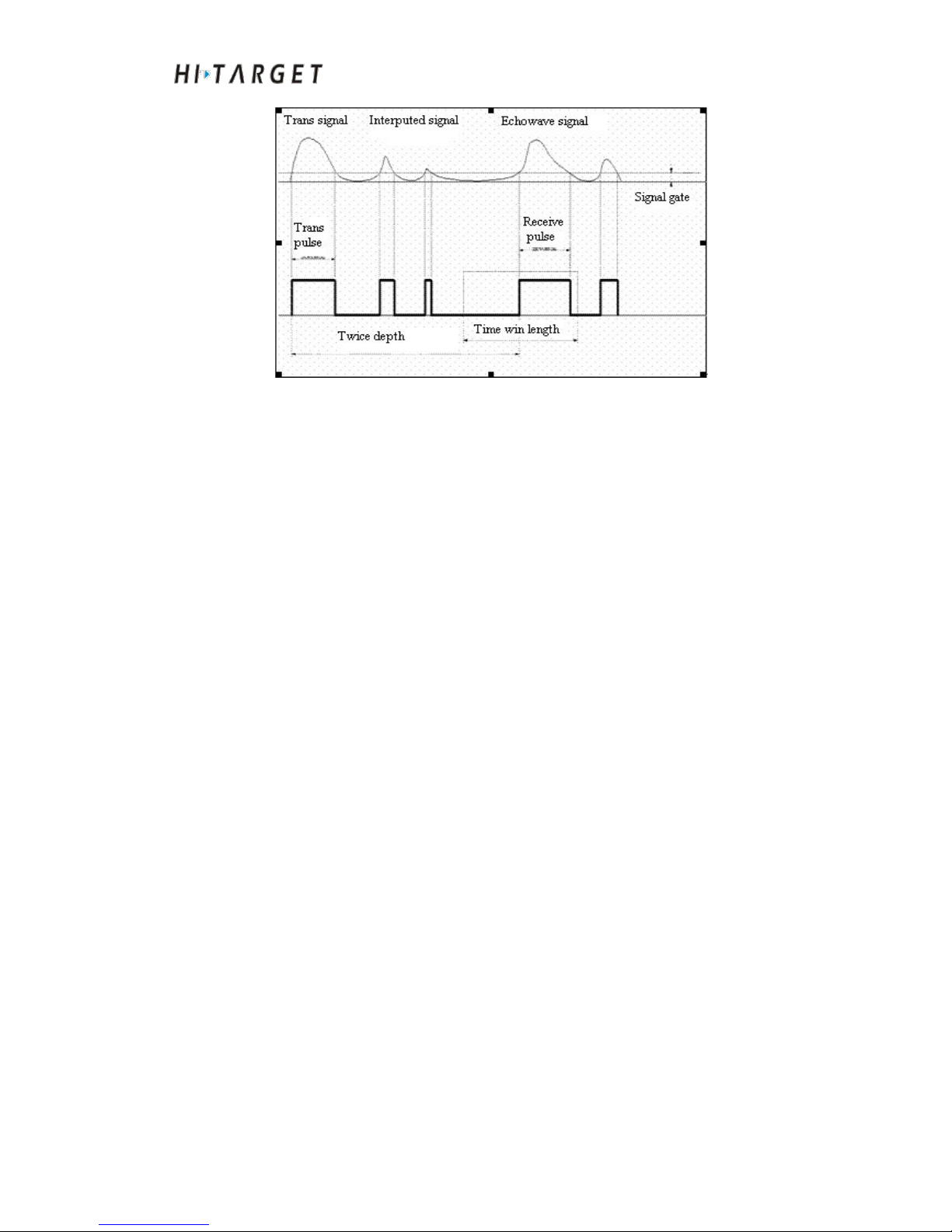
Water bottom gate tracking technology (time gate tracking technology)
Since variations at water bottom are relatively flat, the sounding changes
between two times of depth sounding (about 0.1s) are not too big. Assuming
that the variation of secondary depth is ±10%, a time gate will be set
between 10%*Z before the last correct echo to the next 10%*Z. Only those
echoes within the time gate are correct ones, the ±10% range is referred to
as time door width. Once there is no echo within the time gate, it will
gradually expand the time door until entire echo searching until capturing the
correct echo.
Page 10
HD-MAX Echo Sounder User Guide
10
Figure 1-2
Pulse width selection
In most instances, the echo pulse width at water bottom surface is the Max..
The pulse width of interfering signal and second trip echo are relatively
smaller. Pulse width option is to identify the pulse with the Max. pulse width
as correct echo signal together with time gate.
Signal threshold
If there are more interferences within your measurement area or environment,
signal threshold settings are to be increased thus to filter out interfering
signals. However, signal threshold cannot be too high. Otherwise, it will
also filter out weak echo signal. Different thresholds can affect sounding
accuracy to a certain extent. Thus selection of appropriate signal threshold is
in favor of interference inhibition and stable tracking.
Gain control
Gain control technology is to control amplifying circuit and reduce the gain
in case of too high echo signal to prevent too much interfering signals by
measuring the signal intensity of echo-pulse. When the echo signal is too
small, it will control and receive amplifying circuit automatically and
increase the gain thus to receive echo. The size of gain range is a key factor
to measure receiver performance. The receiving gain control range of
HD-MAX Echo Sounder is 90Db by adopting manual gain control (MGC).
Page 11

HD-MAX Echo Sounder User Guide
11
Time varying gain (TVG)
When the acoustic wave propagates in water, sound intensity will attenuate
according to exponential laws. To maintain stable signal amplitude, TVG will
control the receiving amplifier to increase magnification according to
contrary law, which is the so called TVG.
Product features
Industrial-grade integrated design with multiple functions.
Full edition Windows XP system is adopted with 17" TFT display screen
as well as ultra high hardware configuration.
High strength engineering plastic and reinforced structure design are
adopted to replace traditional metal shell.
Chart display control and various information query functions are
available to realize intuitive display as well as convenient operation.
High equipment integration, information integration and functional
integration.
Technical parameters
Table 5.1 Technical parameters of HD-MAX series products
CPU speed: 1.6G*2
RAM: 2GB
Memory space: 16GB SSD
Display screen size: 17"
Display resolution: 1280*1024
Starting time: < 40s
High frequency emitted from the probe: 200KHZ
Point-positioning precision: <2.5M (built-in GPS function)
Input voltage: 10~30V
Average power consumption: <40W
Operating temperature: 0 ~50˚C
Page 12

HD-MAX Echo Sounder User Guide
12
C H A P T E R
2
Hardware Introduction of HD-MAX
Introduction to this Chapter
■ Front Face of the Host
■ Back Face of the Host
■ Side Faces of the Host
■ Other Accessories
■ Installation size chart
Page 13
HD-MAX Echo Sounder User Guide
13
Front Face of the Host
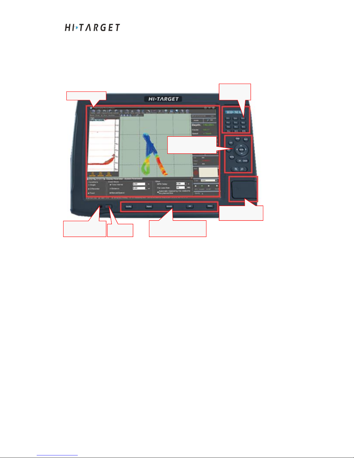
The front face of the host is as shown in the Figure below. It is composed of
display screen, measuring functional keys area: digital keys area, sounding
functional keys area and USB interfaces area.
Figure 2-1
Display screen
17" TFT display screen to realize clear display as well as convenient
operation.
Measuring functional keys area
Include locking, line changeover, recording, marking and other commonly
used functional keys for measuring.
Sounding functional keys area
Include depth sounding, playback, automatically and other commonly used
functional keys for measuring.
USB interfaces area
Open the cover, you can see three USB interfaces available.
Display screen
Measuring function
keys area
Sounding functional
keys area
USB interface
area
On/off
Power indicator
light
Digital
keys area
Page 14
HD-MAX Echo Sounder User Guide
14
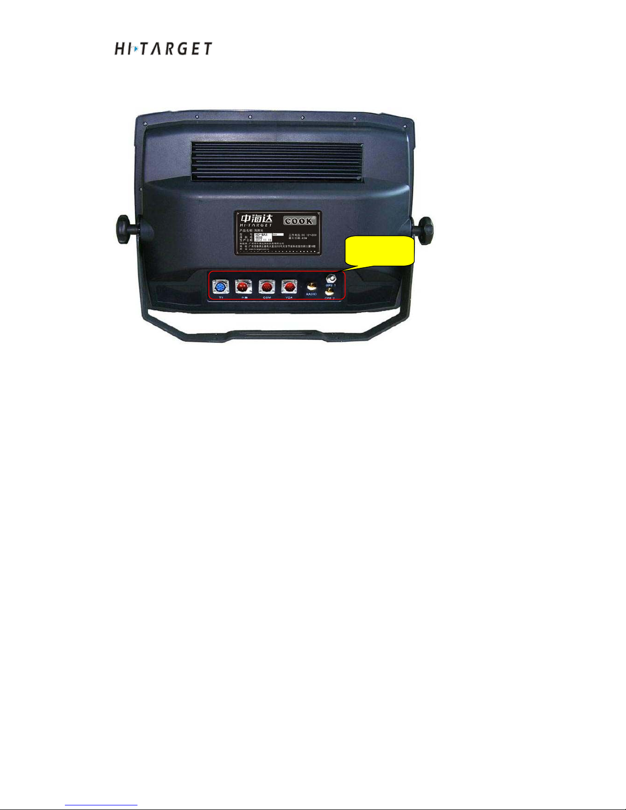
Back Face of the Host
Figure 2-2
The back interfaces of HD-MAX series products include DC10-30V power
interface, high frequency transducer interface, serial data transport interface
(SDTI), VGA display output interface and GPS antenna interface.
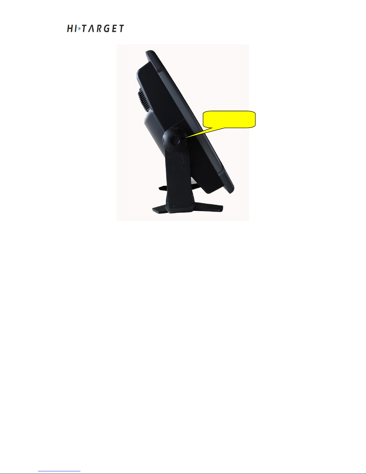
Side Faces of the Host
Back
interfaces
Page 15
HD-MAX Echo Sounder User Guide
15
Figure 2-3
As shown in Figure 2-3, after fixed, the bracket can support the host. The
angle of the bracket can be adjusted randomly by loosening bracket screws.
Other Accessories
Keyboard
The product is equipped with portable and convenient p-p USB interface
keypad which is characterized by good stability, exquisite appearance,
flexible use, as well as excellent hand feeling. It is easy for operation on the
ship.
Mouse
The product is equipped with p-p USB interface mouse with good stability. It
is easy for operation on the ship.
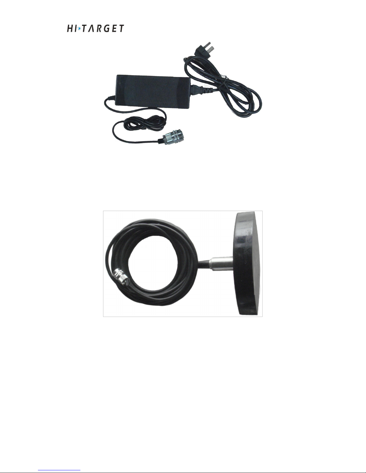
AC power adapter
Bracket fixing
screw
Page 16
HD-MAX Echo Sounder User Guide
16
Figure 2-4
The instrument has a wide input voltage range. It can be applied for 10~30V
DC (nominal input voltage: DC24V) power supply. The standard output is
20V.
High frequency transducer
Figure 2-5
The high frequency transducer is to connect 7 core socket in back interface
board of HD-MAX product.
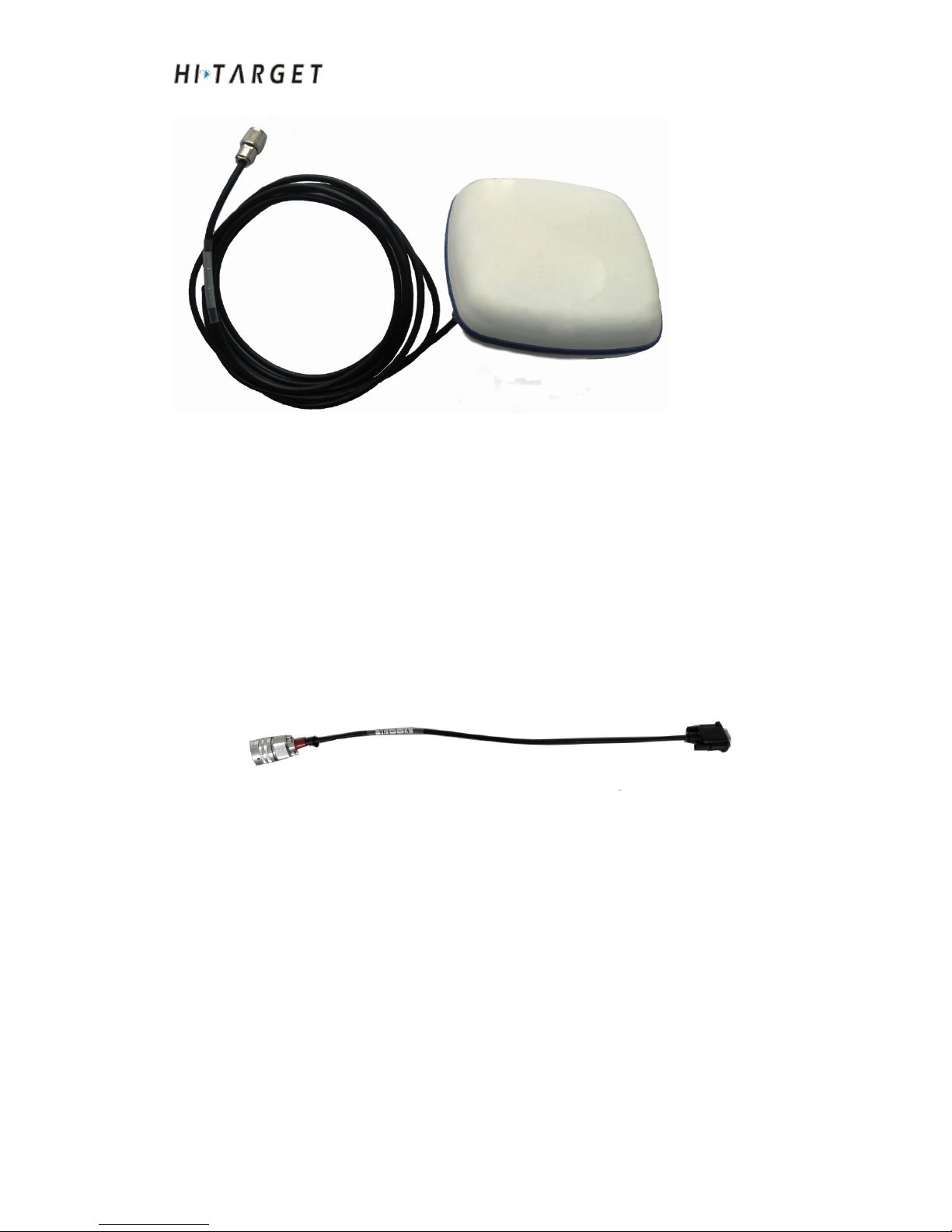
Receiving antenna 1
Page 17
HD-MAX Echo Sounder User Guide
17
Figure 2-7
The antenna is to connect to ANT POS at rear interface board of HD-MAX
products to receive GPS signal. (GPS measuring version of HD-MAX series
products)
VGA patch cord
Figure 2-10
VGA patch cord is used to connect external computer monitor for sub-screen
display.
Page 18
HD-MAX Echo Sounder User Guide
18
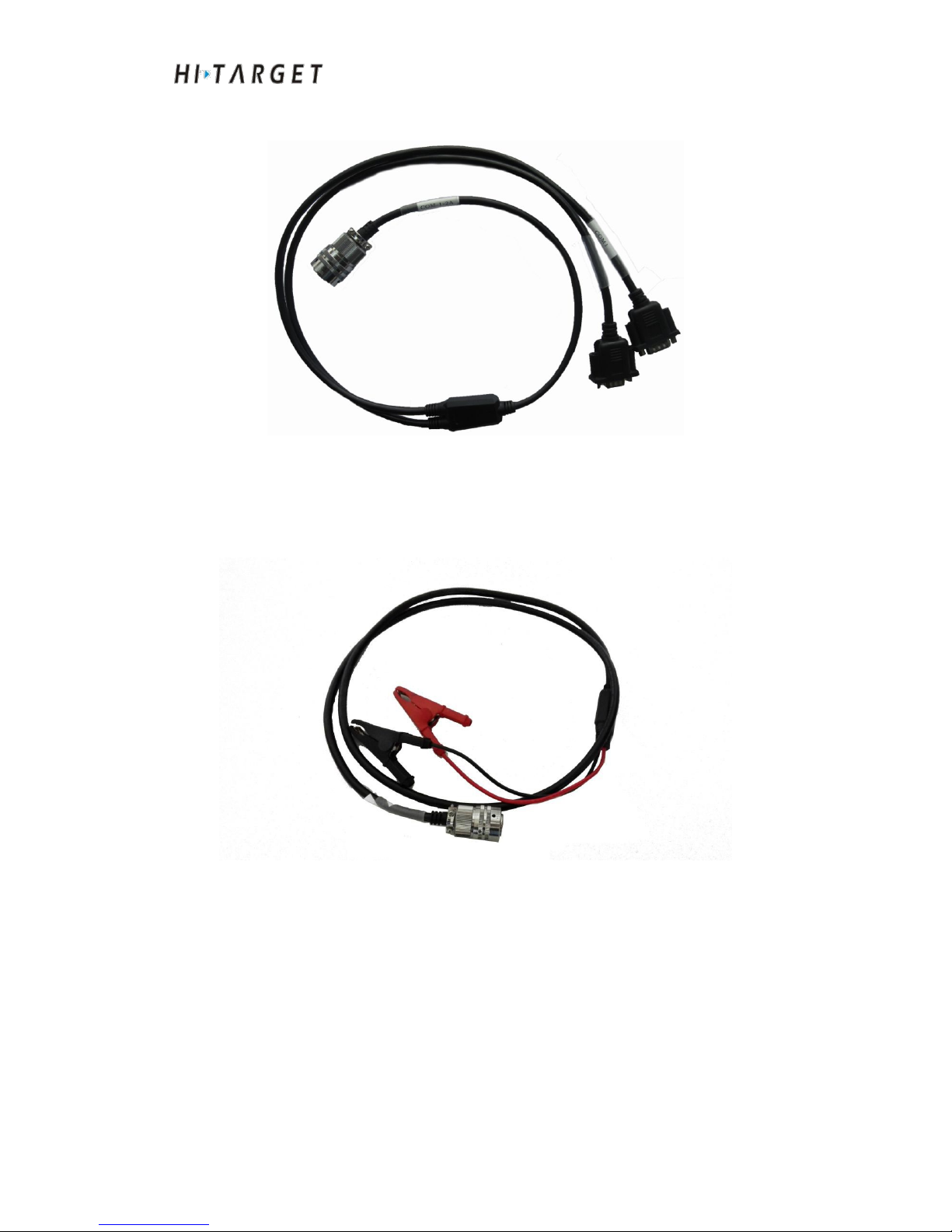
Second full serial port serial port line
Figure 2-11
Second full serial port serial port line is used to external connected to two
RS-232 serial ports
DC power supply cable
Figure 2-12
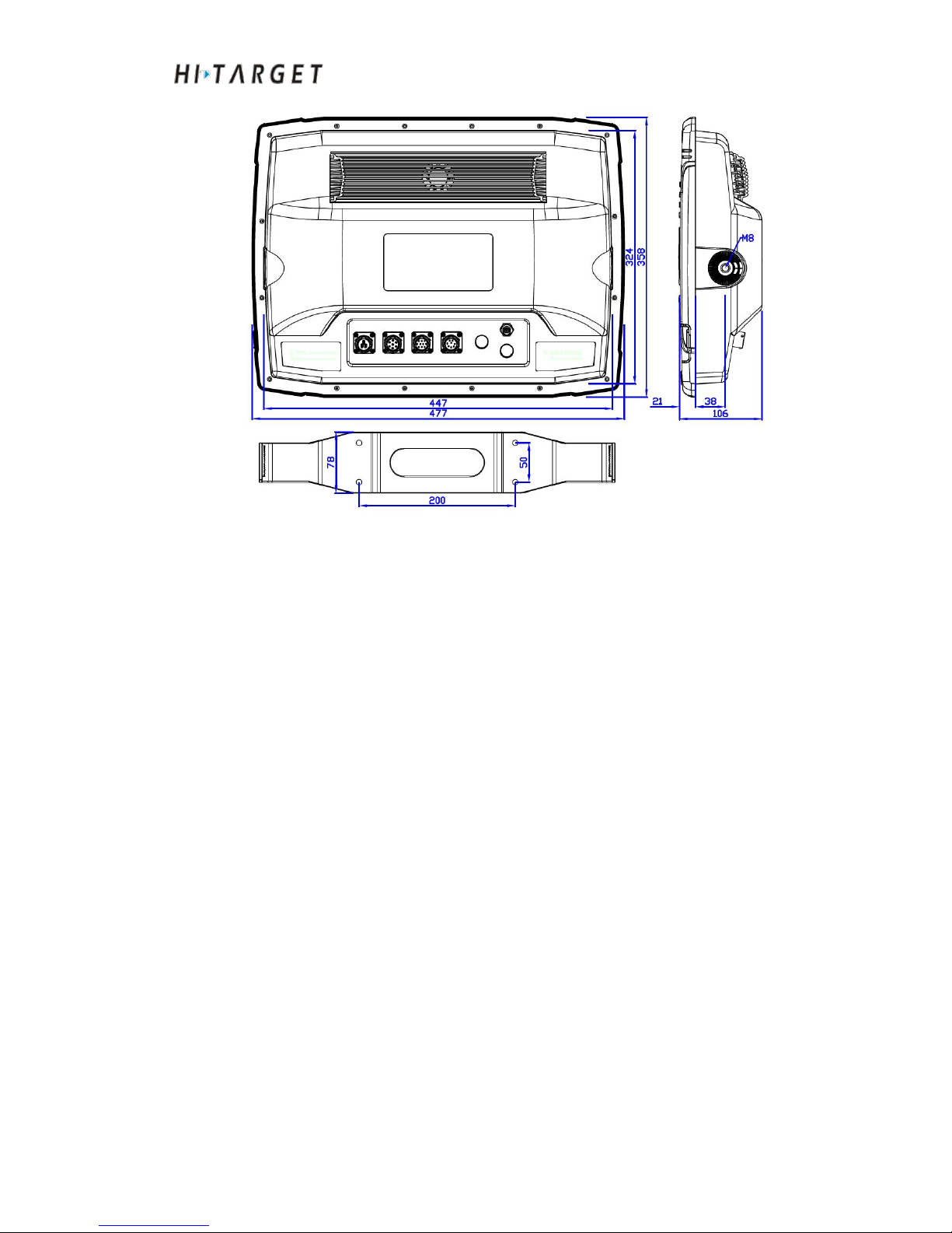
Host installation size chart
Equipment shell size is as shown in Figure 2-7:
Page 19
HD-MAX Echo Sounder User Guide
19
Figure 2-13
Installation Cautions
a) Avoid direct sunlight and high temperature. Avoid strong vibration.
b) Do not plug nor unplug the power when powered on. It is more possible to
facility a DC stabilized power supply of 10-30V.
c) Confirm that there is enough space behind the host in order to install the
plug and cable.
d) Non-professional personnel shall not disassemble the equipment. For any
question, please contact the retailer as soon as possible.
Page 20

HD-MAX Echo Sounder User Guide
20
C H A P T E R
3
Basic operations
Introduction to this Chapter
■ Buttons
■ Keyboard
■ Startup & Shutdown
■ USB Interface
■ Rear panel Interface
Page 21
HD-MAX Echo Sounder User Guide
21
Startup & Shutdown
Startup
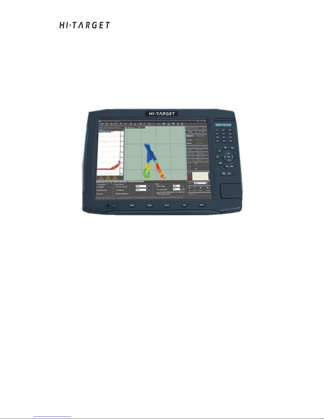
Press power button (about 1s). After the power indicator light is on, loosen to
perform hardware detection and loading system. The whole process of
starting up takes about 1 minute. The system interface after starting up is as
shown in the Figure below:
Figure 3-1
Shutdown
a)Shutdown: Click "Start"->"Shutdown". The software system shall
shutdown.
b)Long press the power button for 5s. After the power supply indicator light
is off, loosen the button and the system will shutdown mandatorily.
Buttons
Measuring function keys
Page 22
HD-MAX Echo Sounder User Guide
22
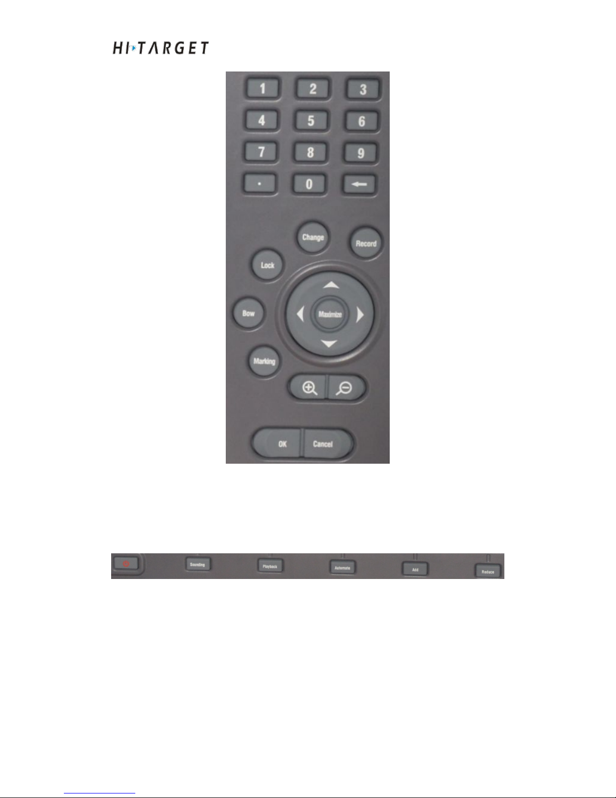
Figure 3-2
Commonly used functional keys for measuring are as shown in the Figure,
include locking, line changeover, recording, as well as marking.
Sounding functional keys
Figure 3-3
Commonly used functional keys for depth sounding are as shown in the
Figure, include depth sounding, playback, automatically, shift up and shift
down.
Confirm/Cancel keys
Page 23
HD-MAX Echo Sounder User Guide
23
Figure 3-4
[OK] key is equal to [Enter] key of the computer. [Cancel] key is equal to
"ESC" key of the computer.
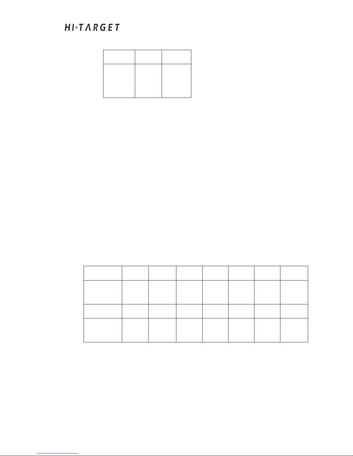
Interface at the backside
Figure 3-5
Transducer interface TX
Transducer interface is used to connect depth measuring high frequency
transducer. It is applied for transmitting and receiving ultrasonic signals with
a transmitting frequency of 200KHZ; after starting up, open the software and
click the "depth". The probe can enter the working position.
Pin definition
Pin
1
263
5
Wiring
definition
Ground
High
and low
frequency
High
frequency
Low
frequency
Cable
characteristics
Shielded
wire
White
line
Red line
Blue line
Power interface DC
The power supply system is an important part of the system. The stable
operation of the instrument is owed to the excellent power supply system.
The rated voltage of the product is 10V~30V DC power supply. Be sure to
keep the voltage within the permissible range to avoid damage to the device.
power interface
serial interface
Transducer interface
VGA interface
antenna interface
Page 24
HD-MAX Echo Sounder User Guide
24
Pin definition
Pin
1
2
Wiring
definition
Positive
Negative
Antenna interface (ANT POS and ANT VEC)
ANT POS and ANT VEC antenna interface are used for antenna connection.
Among them, ANT POS can receive GPS signal and beacon signal
simultaneously; GPS signal is the GPS positioning signal transmitted by
satellites in the sky. Beacon signal is the differential signal transmitted from
the beach beacon station; after the system is powered on, the antenna can
search the satellite signal and the beacon signal.
VGA interface
VGA video output interface can connect video display, such as projector,
monitor etc..
After the system is defaulted as startup, VGA port has output available. You
only needs to connect to the device directly. No other setting is required.
Pin definition
Pin123456
7
Wiring
definition
BLUE
PCGND
SCLNCNC
RED
GREEN
Pin
8
Wiring
definition
SDA
Serial interface
Since HD-MAX series products have many peripheral serial data
communication equipments, more serial ports are required. The expanded
serial interface can satisfy the requirements. HD-MAX series products have
two external RS-232 serial ports (COM1 and COM2) available. Among the
Page 25
HD-MAX Echo Sounder User Guide
25
two ports, the one is connected according to standard 9-pin serial port
definition, and the other one is only connected to communication pin as RX,
TX and GND. The other control pin is not connected. You just need to plug
in your RS-232 serial port.
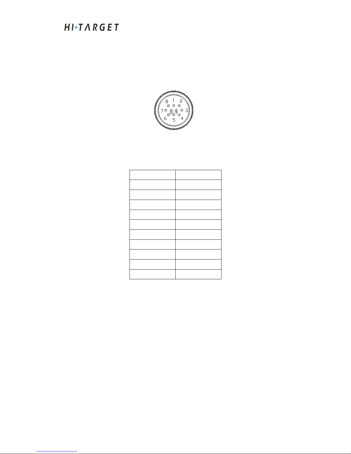
Figure 3-6
Table 3.1 Interface description
Pin
Pin definition
1
TXD2
2
RXD2
3
RTS1
4
RXD1
5
DSR1
6
DCD1
7
DTR1
8
PCGND
9
TXD1
10
CTS1
Initial setting of GPS mainboard
Detailed information is as shown in the software section
Page 26

HD-MAX Echo Sounder User Guide
26
C H A P T E R
4
Software Introduction
Introduction to this Chapter
■ Software Overview
■ Technical Parameters
■ Installation of Software
Page 27

HD-MAX Echo Sounder User Guide
27
Software Overview
The software is Hi-MAX. It is mainly applied on HI-TARGET HD-MAX
series Echo sounders for depth sounding. It can be connected to GPS and
other accessory equipment (such as attitude indicator, electric gyrocompass,
swell instrument). The functions of the software mainly include: project
management, coordinate transformation parameters setting, instruments and
equipment connection, ship design, plan line design, CAD base map import,
chart import, marine surveying, sounding sampling, data correction, tide
level correction, results preview and export, serial port commissioning,
coordinate transformation parameters calculation, coordinate transformation,
software registration and software upgrade.
From the perspective of customers, the software pursuits more precise
measurement, more humanized operation as well as more abundant functions
to realize a variety of measurements. The software has the following
characteristics:
(1) Parameters setting
◇
Support to import the conversion parameters of Hi-RTK handheld
software to realize seamless converting of sea survey parameters and
land measurement.
◇
Support access to attitude indicator, gyrocompass and other sensors.
Attitude algorithm module is available for high precision sounding
measurement.
◇
Support calculating antenna height smoothly and accurately through
inputting water level elevation.
◇
Support serial port tests to resolve results displayed so that the users
can determine that whether the serial port settings are correct or not
conveniently and intuitively.
◇
Support boat design template matching. *.DXF and *.shp boat form
templates can be imported.
(2) Plan line
Page 28

HD-MAX Echo Sounder User Guide
28
◇ Support multiple layout methods for plan lines: channel layout,
parallel layout, vertical layout, area layout and circular sector layout;
◇ Support plan line endpoint capturing with strong plan line editing
functions. Support retracement and restoration functions.
◇ Support plan line preparation with mouse and coordinate input.
Furthermore, parallel operation is permitted; support points library
drawing.
◇ Support importing DXF format plan line; support to export plan line
to DXF format.
(3) Marine surveying
◇ Support synchronous acquisition of geographical coordinates and
sounding, namely the coordinate point collection is consistent with the
output of Echo sounder.
◇ Support patterns of middle ship position and ship heading.
◇ Support to display electronic chart, DXF engineering map and
support electronic chart feature query.
◇ Support point, line, curve fitting, surface marks, as well as inland
waterway common schema tags which can be exported to DXF format.
◇ Soundings display supports multiple color modes such as
monochrome, two-color, ribbon, depth color customization; soundings
display modes support square, round cakes, depth value and so on.
◇ Shallow-water alarm, speed alarm, data acquisition anomaly alarm
and other common alarm functions are available. Support text and voice
prompts.
◇ With survey line management functions. Can export line data
user-defined format, and can show/hide the survey line.
◇ Support track data acquisition in case of not connecting to Echo
sounder.
(4) Marine sounding
Page 29

HD-MAX Echo Sounder User Guide
29
◇ Support manual and automatic adjustment of gain, threshold, and
power.
◇ Support color schemes manual configuration of echo, sounding line,
waterline and other elements.
◇ Support manual and automatic gear
◇ Automatic capture undersounding
◇ Support echo, geographical position synchronous recording
◇ Support echo, geographical position synchronous playback
(4) Data post-processing
◇ Support manual acquisition of soundings as well as manual soundings
editing.
◇ Support median method, weighted average, statistics and other
automatic filter method.
◇ Support coordinate transformation parameters correction, delay
correction, water surface elevation correction as well as draft correction.
◇ Support mono-station correction, regional multiple correction, fixed
difference correction and a variety of tidal correction methods.
◇ Support depth contour and in-depth pseudo color rendering generated
by achievement database.
◇ Support achievement data export. Support to export XYZ, DAT and
other common data formats. Support export of user-defined formats.
◇ Support to edit sounding points according to echo.
◇ Support high and low frequency switching functions
(5) Other aspects
◇ With HI-TARGET GPS instrument (RTK/beaconreceiver/positioning
& heading receiver), parameter setting, mainboard command
transmitting and other relevant functions
◇ With coordinate transformation parameters calculation, distance and
orientation calculation and other functions.
Page 30
HD-MAX Echo Sounder User Guide
30
◇ Support software online updating and software offline upgrading.
Technical parameters
Operating environment: X86 system platform, CPU: Not smaller than 1GHZ.
The internal storage shall not be less than 1GB.
Operating system: WindowXP or Windows7
Language environment: Support Chinese and English
Installation of Software
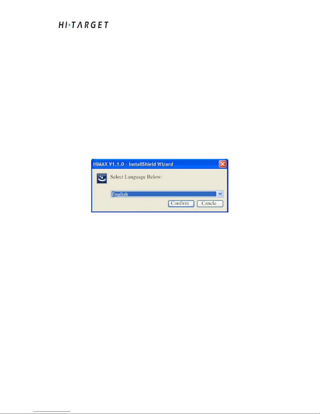
Double-click software installation package. A language selection dialog box
will popup.
Figure 4-1 Installation language selection
Click [Confirm] to enter the next step:
Page 31
HD-MAX Echo Sounder User Guide
31
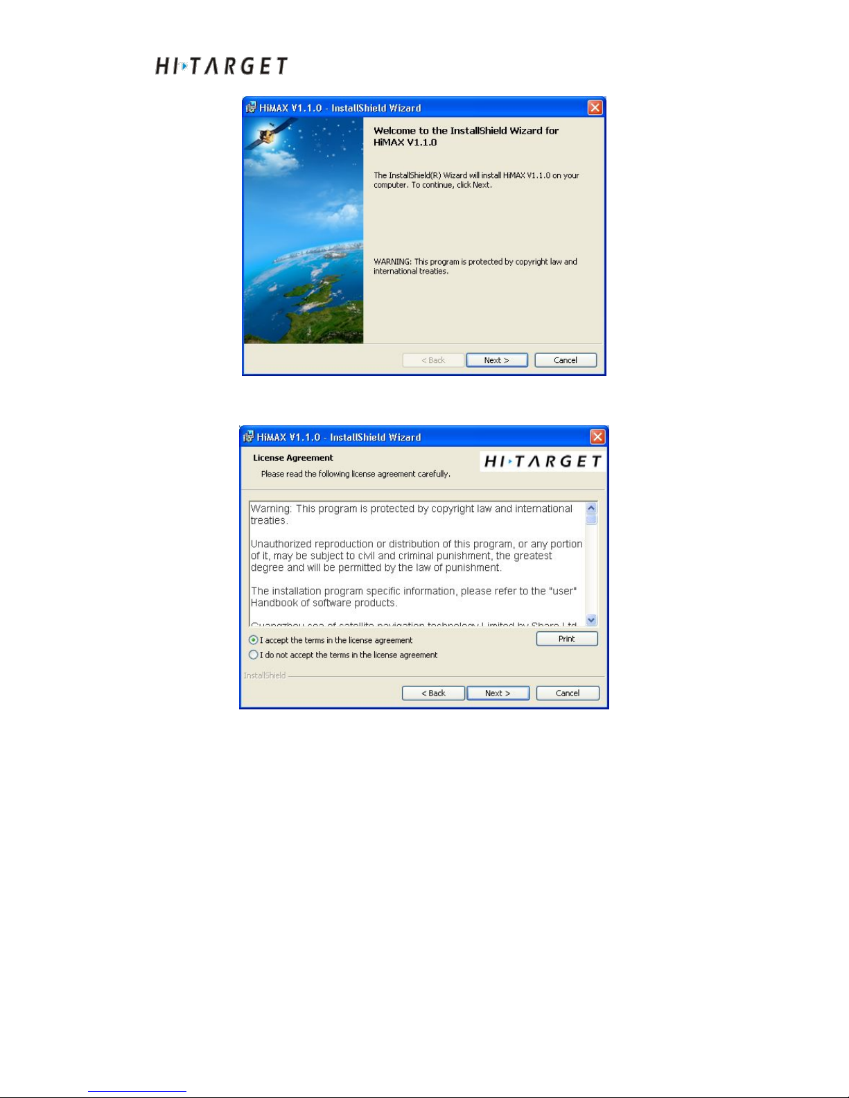
Figure 4-2 Install the initial interface
Click [The next step]
Figure 4-3 License agreement
Select [I accept the …]. Click [Next]
Page 32
HD-MAX Echo Sounder User Guide
32
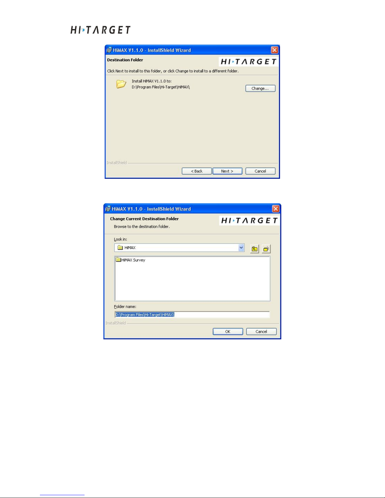
Figure 4-4 Installation directory
Click [Change] to change software installation directory:
Figure 4-5 Installation directory setting
Modification completed. Click [OK] and click [Next]:
Page 33
HD-MAX Echo Sounder User Guide
33
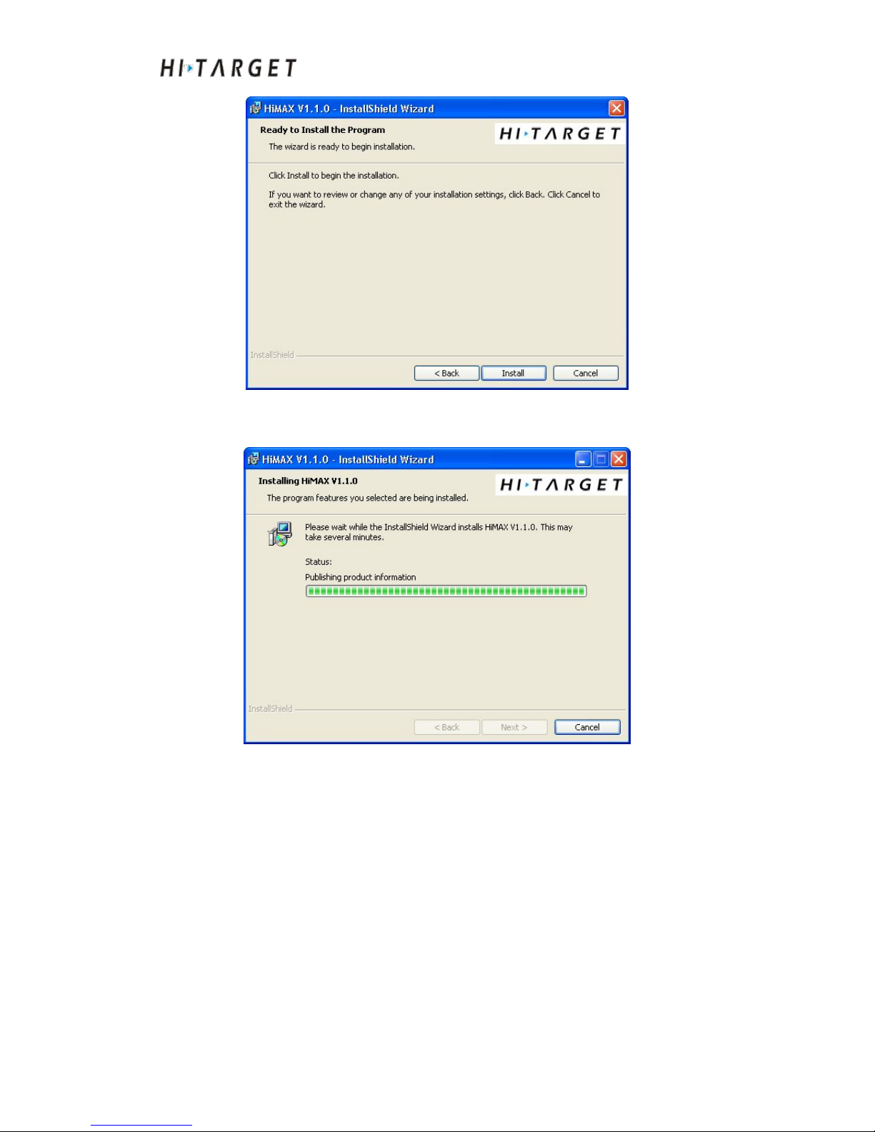
Figure 4-6 Start installation
Click [Install] to start installation:
Figure 4-7 Start installation
After complete the installation, click [Finish] and exit the interface:
Page 34
HD-MAX Echo Sounder User Guide
34
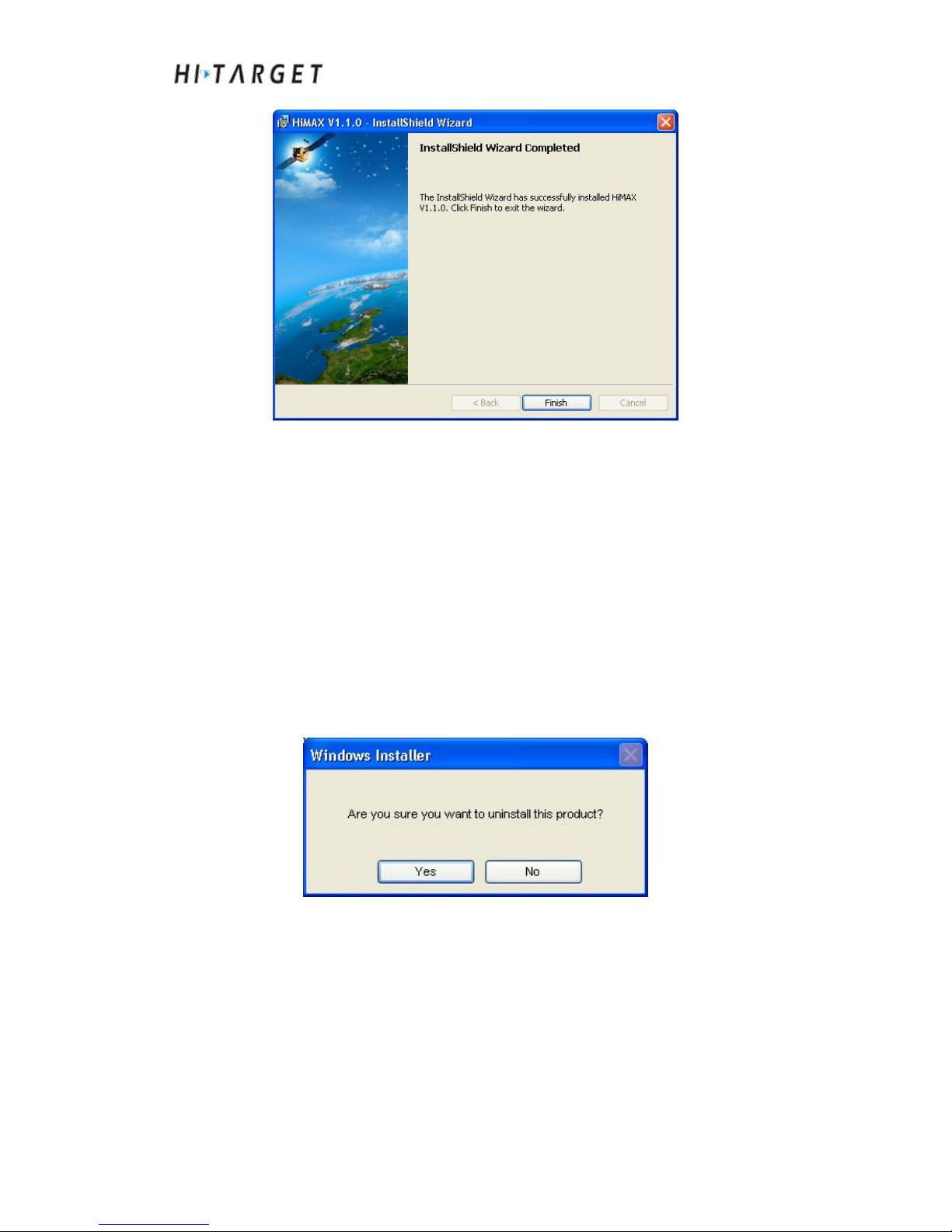
Figure 4-8 Installation completion
After successful installation, start menu will display installation directory.
And shortcut icons of starting the software and uninstall the software are
available.
Software uninstall
There are two methods to uninstall the software:
(1) Run the built-in uninstall program
Under the secondary menu, Hi-MAX, of Start Menu, the shortcut icon
Uninstall Hi-MAX of uninstall program is available.
Figure 4-9 Start uninstall
Click [Yes] to continue and [No] to exist current operation.
Page 35
HD-MAX Echo Sounder User Guide
35
Figure 4-10 Start uninstall program
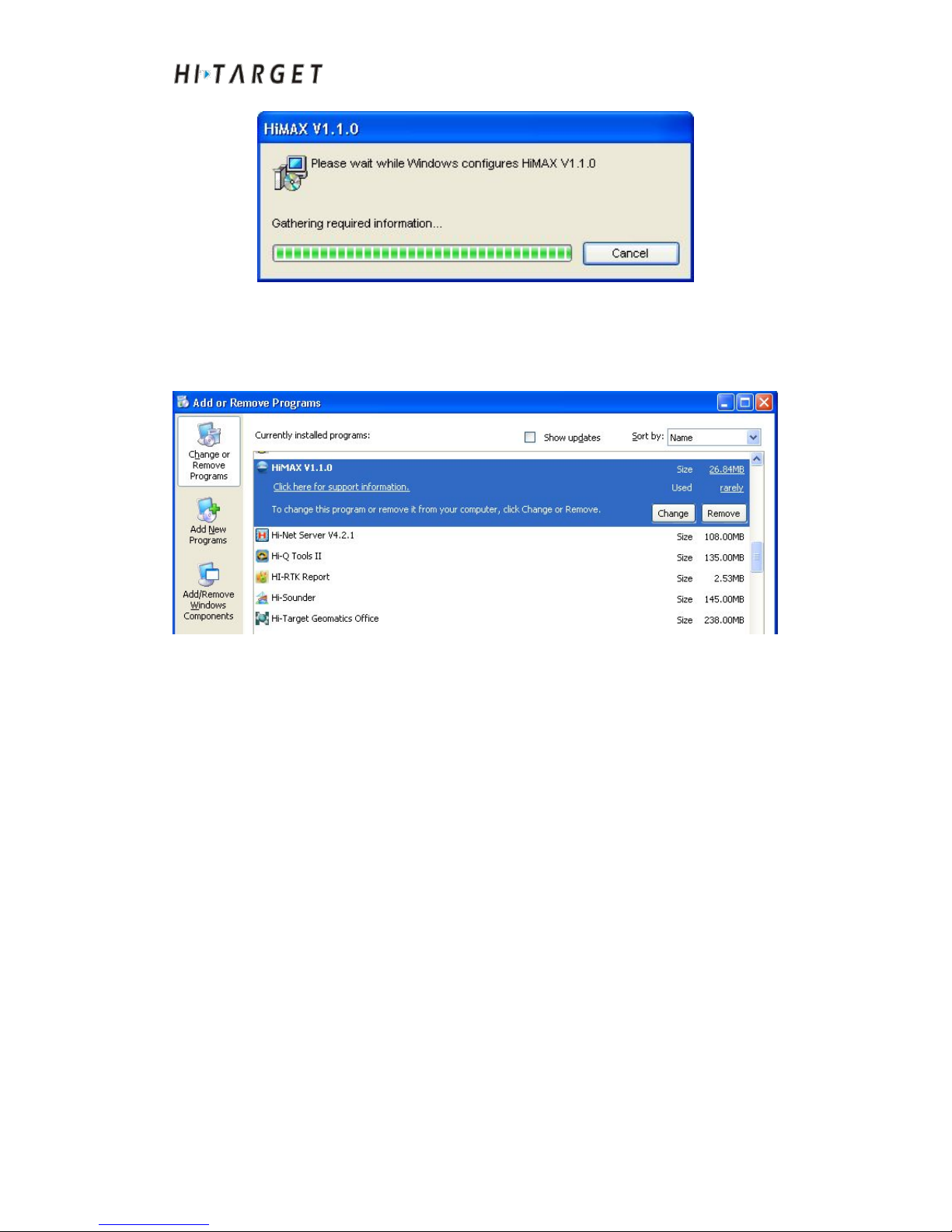
(2) Program uninstall of the system
Find out the Hi-MAX software in "Add or remove programs":
Figure 4-11 Add or remove programs
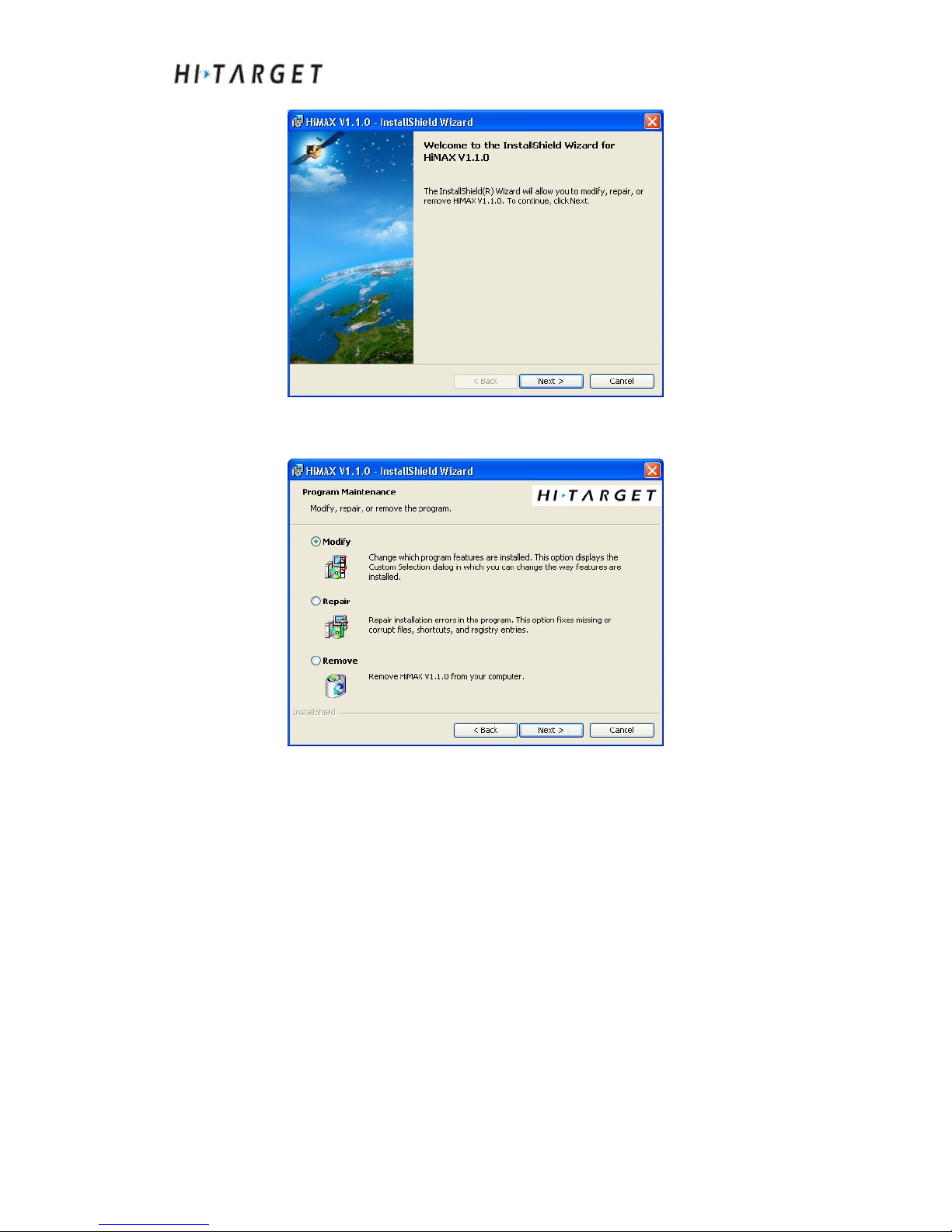
Click [Remove] to uninstall the software directly. Select [Change] to enter
uninstall interface:
Page 36
HD-MAX Echo Sounder User Guide
36
Figure 4-12 Modify the program
Click [Next] to continue:
Figure 4-13 Software maintenance
Select Modify, Repair, or Remove to perform relevant operations.
Page 37

HD-MAX Echo Sounder User Guide
37
C H A P T E R
5
Simple Operation Process
Introduction to this Chapter
■ Main Interface
■ Simple Operation Process
■ Conclusion of This Chapter
Page 38
HD-MAX Echo Sounder User Guide
38
Main Interface
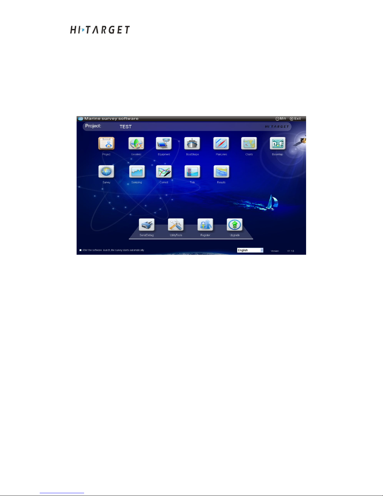
Run the software to enter the main interface. The main interface includes
project name, module button, automatic measurement selection, English and
Chinese selection, and version number. Select relevant modules for
operation.
Figure 5-1 Software main interface
◇
"Current item" is the current default item name.
◇ Check "Software startup for automatic measurement" and the
measurement interface can be entered automatically after next startup.
◇
Select "Chinese" or "English" Environment. Software is to switch
between languages.
◇ At the lower right corner is the current software version.
◇
Module buttons are available on the main interface. Click it to enter
corresponding module interface.
Simple Operation Process
1.Click [Project] to create new project. Open, import, apply and delete
current projects. (Declaration: After starting up the software,
automatically open the last project. If the project is opened, this step can
be omitted).
Page 39

HD-MAX Echo Sounder User Guide
39
2.Click [Geodetic]. Set up central coordinate system. According to seven
parameters, four parameters, elevation fitting parameters, points
transformation parameters and transformation parameters. (Description:
The [UtilityTools] module of the software can provide coordinate
parameter calculation. The results calculated by the functional
parameters can be applied in [Geodetic]; [Geodetic] module supports
parameter files importing functions can import parameter files of *.dam
format and support item parameters of importing V60 controller. If the
user do not perform any modification to current coordinate parameters,
the step can be omitted.)
3.Click [Equipment] to connect any types of GPS, Echo sounders,
compass, attitude indicator and swell instrument. (Description: This
software supports most types of GPS, Echo sounders, compass, attitude
indicators and other equipment. Sounder data format can self-define. For
the few and unknown instrument, it can be connected to the software
based on international NMEA0183 standard format).
4.Click [BoatShape] and select hull lines model. Set length, width,
position transducer, GPS antenna and other parameters. (Description: In
this step, only the deviation parameter of GPS antenna position and
transducer position will affect measuring results. The parameters need
accurate measurement and then input to the software. The other
parameters can be input roughly.)
5.Click [PlanLines]. Draw plan line with a mouse, coordinates and
coordinates library. The DXF format plan files can be imported/exported.
(Description: This software provides parallel layout, vertical layout,
regional layout, fan layout, channel layout and other layout model to
facilitate rapid layout).
6.Click [Charts]. Encrypted S63 electronic chart can be imported.
Unencrypted S57 electronic chart can be imported. (Description: If the
electronic chart is unnecessary, this step can be ignored).
7.Click [BaseMap] to import engineering basemap in DXF format.
Sounding data basemap in DAT format or user-defined format can be
imported. (Description: If the engineering basemap is unnecessary, this
Page 40

HD-MAX Echo Sounder User Guide
40
step can be ignored.)
8.Click [Survey] to enter measuring interface. Click [Record] button to
perform data acquisition and recording automatically. During the
measuring process, chart query, plan line preparation, marking, distance,
angle measuring and other functions can be applied. (Description:
Among all measuring modules, mode switch can be performed between
[North up] and [Head up]. It can switch between [Unlock] and [Locked]
to control whether the ship position is displayed in the middle).
9.Click [Sampling] to amend error sounding data, data resampling and
other data processing. (Description: The software can provide median
filtering, weighted average, statistics and other mathematical models.
The software can perform automatic correction to the wrong sounding
data quickly and efficiently.)
10.Click [Correct]. It can perform coordinate transformation parameters
correction, delayed correction, surface elevation correction and draft
correction. (Description: At data acquisition, if the coordinate
transformation parameters input wrongly, coordinate transformation
parameter correction can be adopted to correct them.)
11.Click [Tide] to input water level information of tide station. And then
perform tide level correction for result data of [Sounding sampling].
(Description: For RTK operation, this step can be ignored.)
12.Click [Results] to preview the depth contour and pseudo color
rendering images according to result data of [Sampling] or [Tide]. If you
are satisfied about the result, you can export the achievement data to
complete the whole process. If not, you can repeat the process after go
back to [Sampling] or [Tide].
The above contents are brief operation process of sounding and the
followings are software assistant functions.
1.Click [SerialDebug] to view satellites information. The base station
information or Rover instrument parameters can be set up. Or serial port
command can be transmitted to mainboard of the instrument.
2.Click [UtilityTools]. You can calculate seven-parameter,
Page 41

HD-MAX Echo Sounder User Guide
41
four-parameter, elevation fitting parameters. It has coordinate
transformation calculation, distance azimuth calculation, unit conversion
and other functions.
3.Click [Register] and input the registration code to register the Software
Dongle.
4.Click [Upgrade] to perform software online or offline upgrade
packages upgrading.
5.In the case of [After the software launch, the survey starts
automatically] being selected, the software will automatically enter
[Survey] functional module at software starting.
Conclusion of This Chapter
The software interface is simple, efficient, and easy to understand. The
complete modularization design has greatly facilitated operation. Users can
complete basic operations of marine surveying following the sort order
specified on software interface. Besides, the software provided abundant
utilities for easy and rapid operation.
Page 42

HD-MAX Echo Sounder User Guide
42
C H A P T E R
6
Project management
Introduction to this Chapter
■ Project Settings
■ Conclusion of This Chapter
Page 43
HD-MAX Echo Sounder User Guide
43
Project Settings
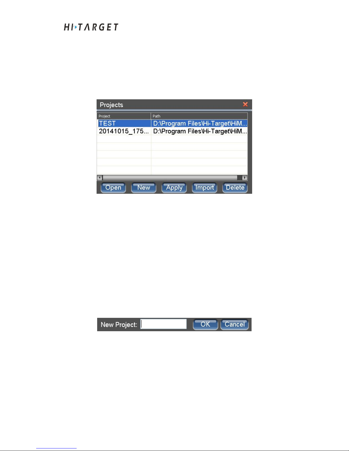
At the main menu interface, click [Project], a dialog box as shown in Figure
6-1 will popup. You can view the existing project tasks, open a project,
establish a project, template application, import a project, delete a project etc.
Figure 6-1 Project task
Open a project: Select a project in the list. Click [Open] to open the current
project; if it is opened successfully, it prompts that the project has been
opened successfully. And then exit the interface; if it prompts any failure,
please choose whether delete it or not.
Establish a project: Click [New], and the interface to input a new project
name will show up (as shown in Figure 6-2]. Input the name of a new project.
Click [OK] to establish a new project. Click [Cancel] to exist new project
operation.
Figure 6-2 Establish a project
Template application: First of all, select the project in the list. Click [Apply],
and the interface to input a new project name will show up (as shown in
Figure 6-2]. Input the name of a new project. Click [OK] to establish a new
project. The new project will use the template application automatically for
item parameters selected. Click [Cancel] to exist template application
Page 44

HD-MAX Echo Sounder User Guide
44
operations.
Import the project: Click [Import]. A dialog box (*.pgm) that reminders
open the project file will pop up. Select the project engineering files that have
to be imported and open them. The items imported successfully will be
displayed in the project list to facilitate other operations in the future.
Delete the project: First of all, select the projects in the list. And then, select
[Delete] to delete the project selected from the project list. In order to avoid
data loss caused by misoperation, [Delete] function will only delete the
project from the project list, but not delete the project specific data.
Conclusion of This Chapter
After the software starting up, it will open the project that opened at last time
automatically. Only when you need to open the other projects, [Open]
functional key will be used; for the first time of running the software, the
software will automatically create a default project. The project will be
named after a date for project construction. The difference between [Apply]
and [New]: [Template application] is to copy the parameters of the selected
project to create a new project. [New] is create a new project with all
parameters as default values. [Import] only imports the projects at other
memory locations to project list but will not remove data storage location.
[Delete] only deletes the project from the project list, but will not delete
specific data.
Page 45

HD-MAX Echo Sounder User Guide
45
Coordinate parameters
Introduction to this Chapter
■ Coordinate Transformation Parameters Settings
■ Conclusion of This Chapter
CHAPTER
7
Page 46
HD-MAX Echo Sounder User Guide
46
Coordinate Transformation Parameters Settings
At the main menu interface, click [Geodetic] to enter coordinate
transformation interface. It is possible to import existing coordinate
conversion parameters to import existing coordinate transformation
parameters in other projects rapidly; the coordinate conversion parameters
used previously can be used as the conversion parameters of current project;
can set/modify coordinate transformation parameters of current project,
including ellipsoid parameters, projection parameters, ellipsoid
transformation parameters, plane transformation parameters, elevation fitting
parameters, points transformation parameters and plane grid parameters.
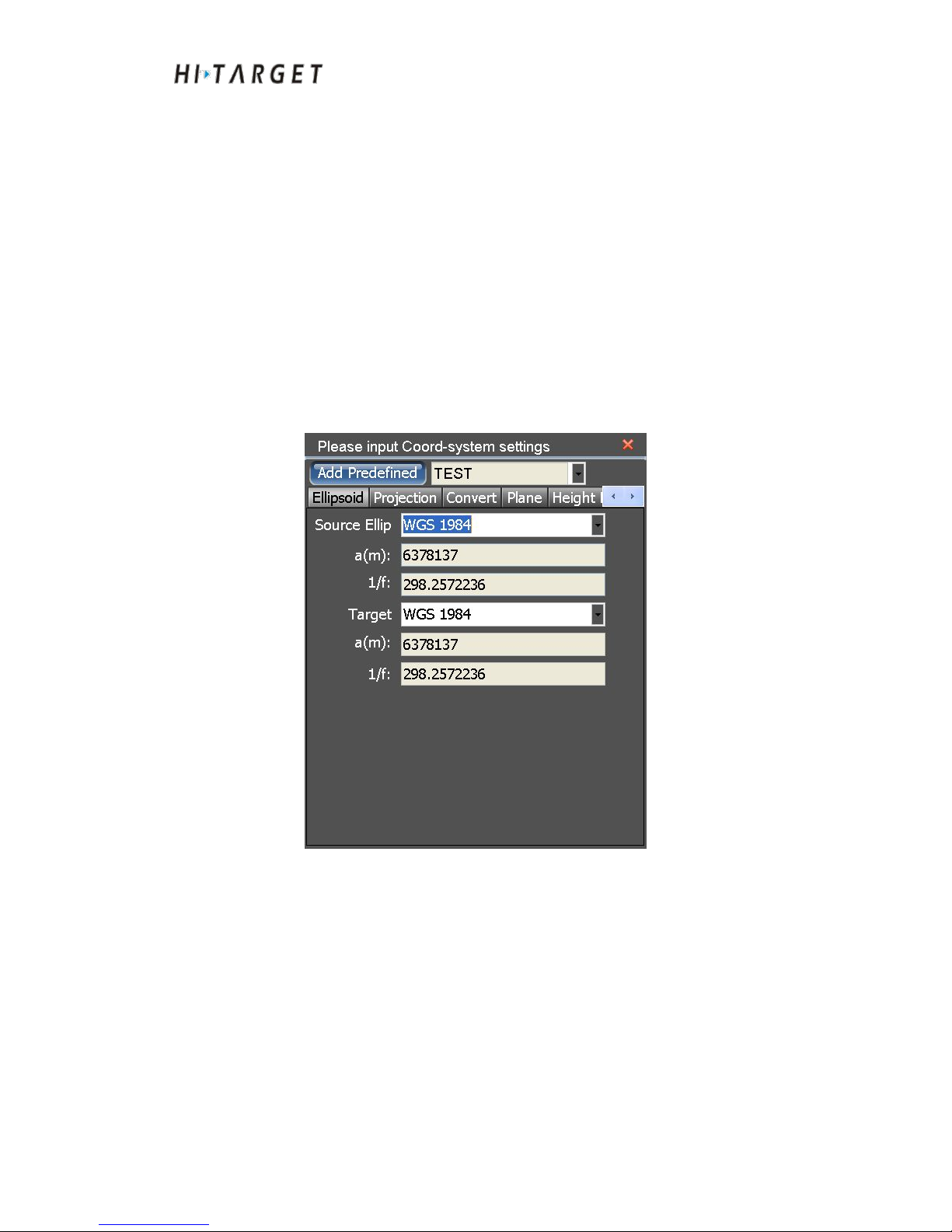
Figure 7-1 Coordinate parameters
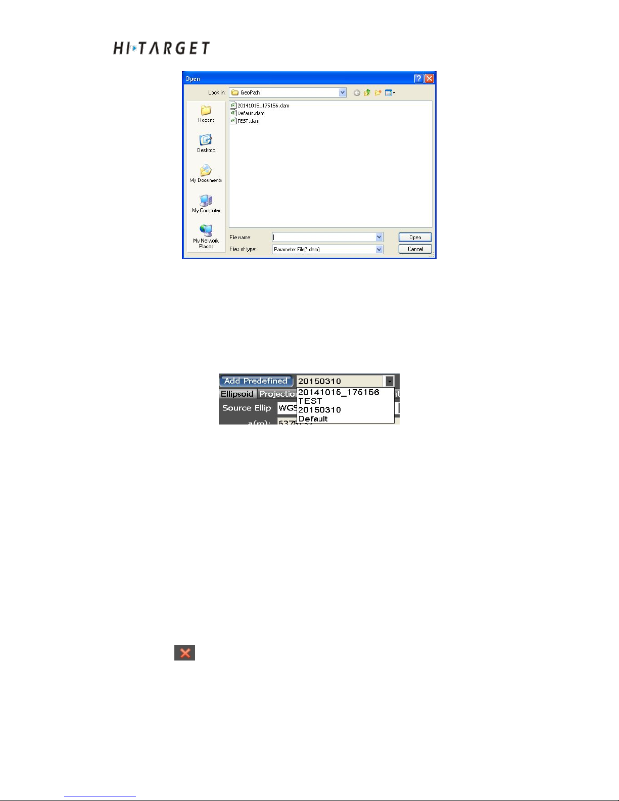
Import coordinate transformation parameters: Click [Add Predefined].
The dialog box of opening the file will pop up. The file type can be selected
as (*.dam) or (*.Prj). And then open the parameter files. The function
supports to open existing Hi-RTK project files (*.Prj). Besides, it can open
the coordinate conversion parameter files of other projects (*.dam) as well.
Page 47
HD-MAX Echo Sounder User Guide
47
Figure 7-2 Parameters importing
Choose existing coordinate transformation parameters: The coordinate
transformation parameters used recently are shown in the parameter
pull-down list at the right side of [Import] button. Select a project to set the
coordinate transformation parameters of the project as coordinate parameters
of the current project.
Figure 7-3 Parameters selection
Set/modify coordinate transformation parameters: Coordinate
transformation parameters include ellipsoid parameters, projection
parameters, ellipsoid transformation parameters, plane transformation
parameters, elevation fitting parameters, points transformation parameters
and plane grid parameters. The setting of these parameters shall follow strict
sequence. The parameters that have to be set up frequently include projection
parameters, plane transformation parameters, elevation fitting parameters and
points transformation parameters.
Saving coordinate transformation parameters: Import coordinate
transformation parameters or select existing ones, or set/modify coordinate
transformation parameters. After completing such operations, click the
icon at top right corner. The software will save current setting of
coordinate transformation parameters automatically.
Ellipsoid setup
Ellipsoid parameters include source ellipsoid and local ellipsoid. Generally,
Page 48
HD-MAX Echo Sounder User Guide
48
WGS84 is adopted as source ellipsoid and Beijing 54 as local ellipsoid in
China.
Figure 7-4 Ellipsoidal parameter
Projector setting
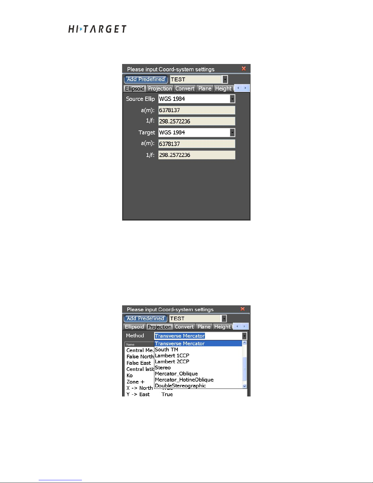
The role of projection parameters is to achieve the transformation from space
rectangular coordinate system to plane rectangular coordinate system.
Choosing different projection methods will obtain different plane coordinates
correspondingly. The most frequently-used projective modes include
"Mercator", "Transverse Mercator", "Gauss -define" and so on.
Figure 7-5 Projective modes
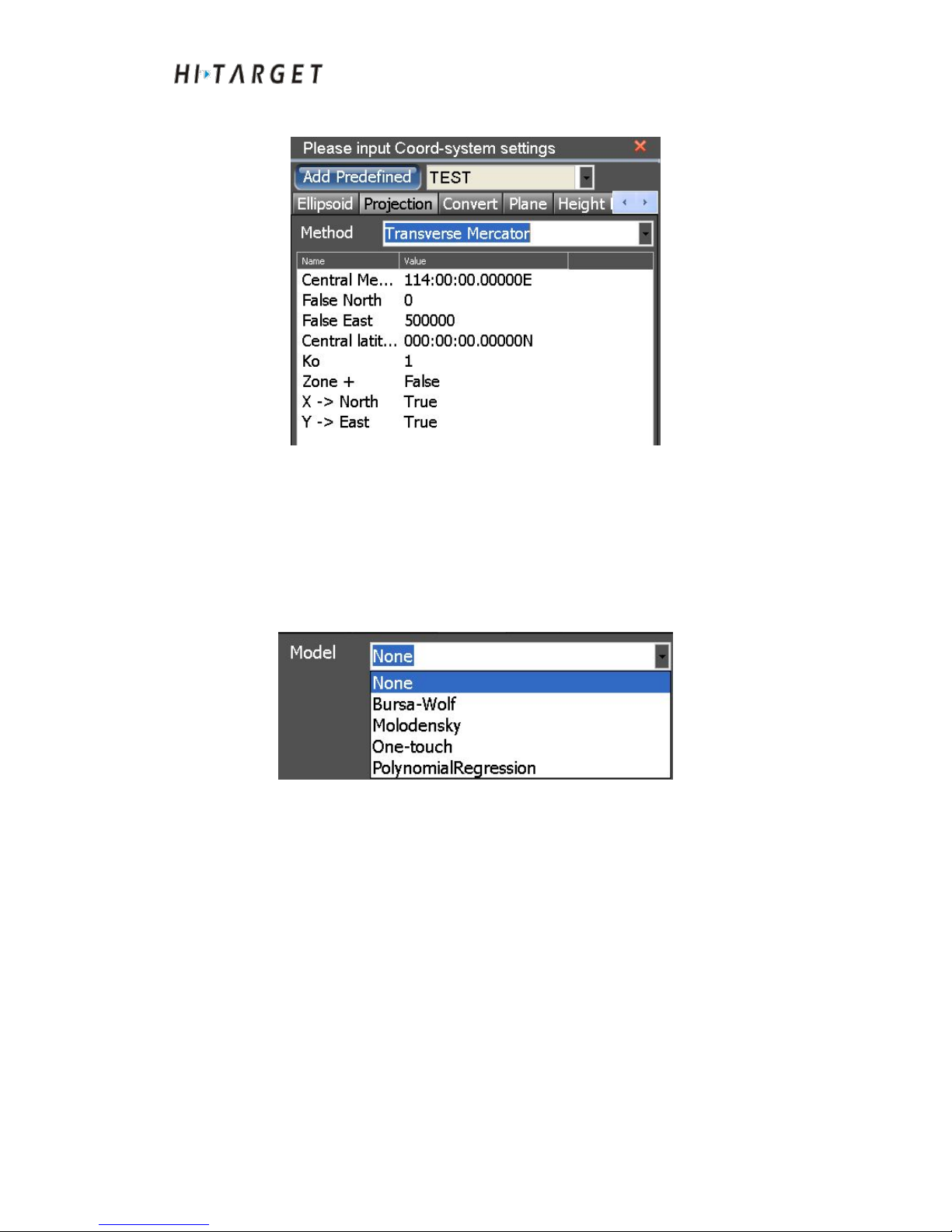
Major parameters of projective modes setting include central meridian, north
with constants, east with constants, scale etc.. Generally, north with constants,
east with constants, scale are fixed constants. Users only need to set the
Page 49
HD-MAX Echo Sounder User Guide
49
central meridian corresponding to the projection mode.
Figure 7-6 Projection parameters
Ellipsoid transformation
Ellipsoid transformation parameters are to complete the transformation from
source ellipsoid space rectangular coordinate system to local ellipsoid space
rectangular coordinate system. The most frequently-used transformation
methods include: Bursa-Wolf, Molodensky, One-touch etc.
Figure 7-7 Transformation model
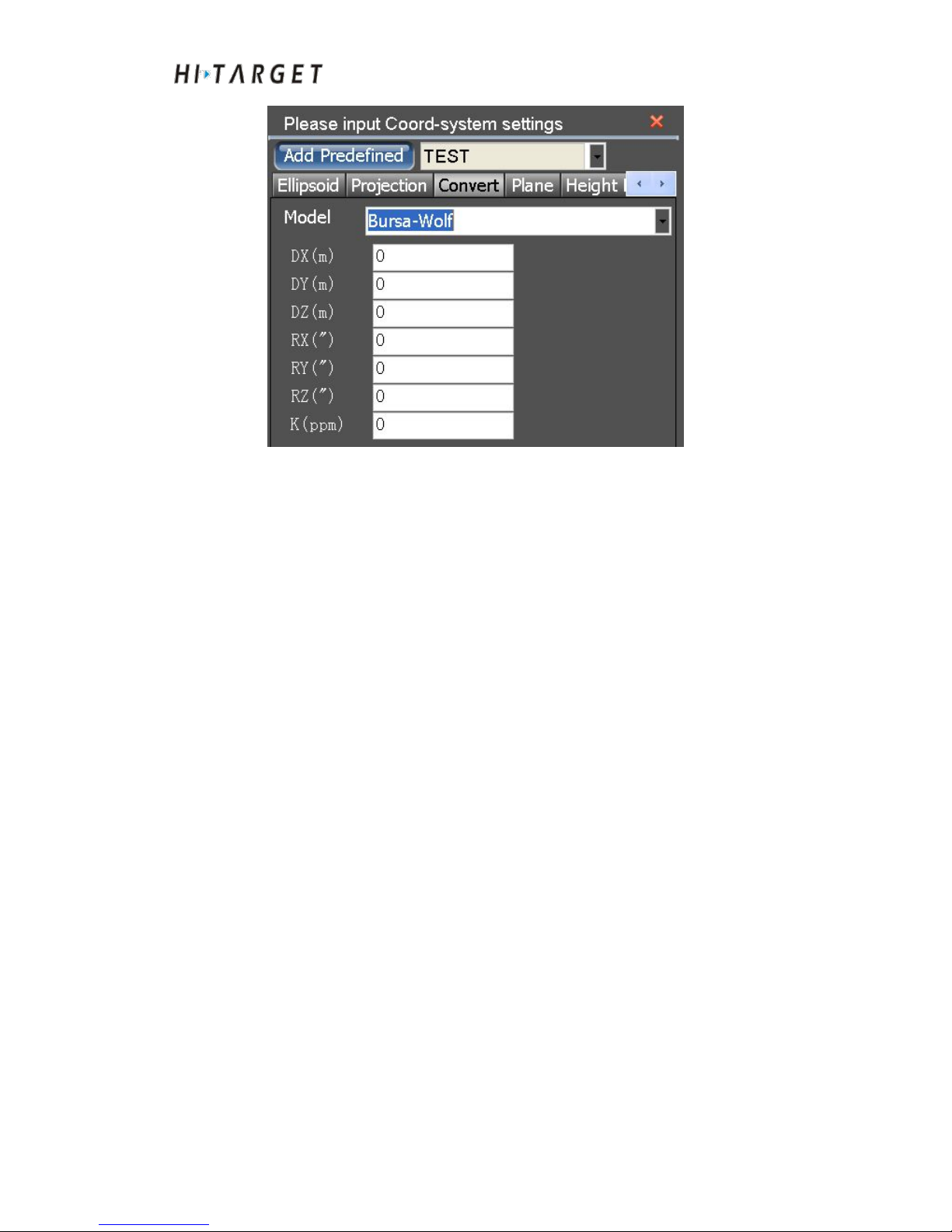
Set up parameters based on the selected ellipsoid transformation model or
acquire the parameters through Utilities, such as seven-parameter:
Page 50
HD-MAX Echo Sounder User Guide
50
Figure 7-8 Seven-parameter
Description of several commonly used Ellipsoid transformation parameters
(1) Bursa-Wolf
Transformation, rotation and scale parameters at spatial vector between two
ellipsoids with extremely small rotation angle is a rigorous transformation
model. At least, three points are required for calculating. It is applicable to
transformation from WGS-84 to national coordinate system.
(2) Molodensky
It is a simplifying form of Bursa-Wolf method, only with transformation
parameters at spatial vector. It is a transformation method with lower
precision. It can calculate from a given point. It is applicable to
transformation from WGS-84 to national coordinate system.
(3) One-touch
Combination of transformation, rotation, scale parameters as well as plane
transformation parameters at spatial vector between two ellipsoids. The
rotation angle can be as an arbitrary value. At least, three points are required
for calculating. It is applicable to transformation from WGS-84 to any
coordinate system.
Page 51
HD-MAX Echo Sounder User Guide
51
Attention: Users shall pay attention to coherent units of
seven-parameter. Especially when the "K" value dimensional unit is
ppm (percent per million), users shall pay more attention at
inputting!
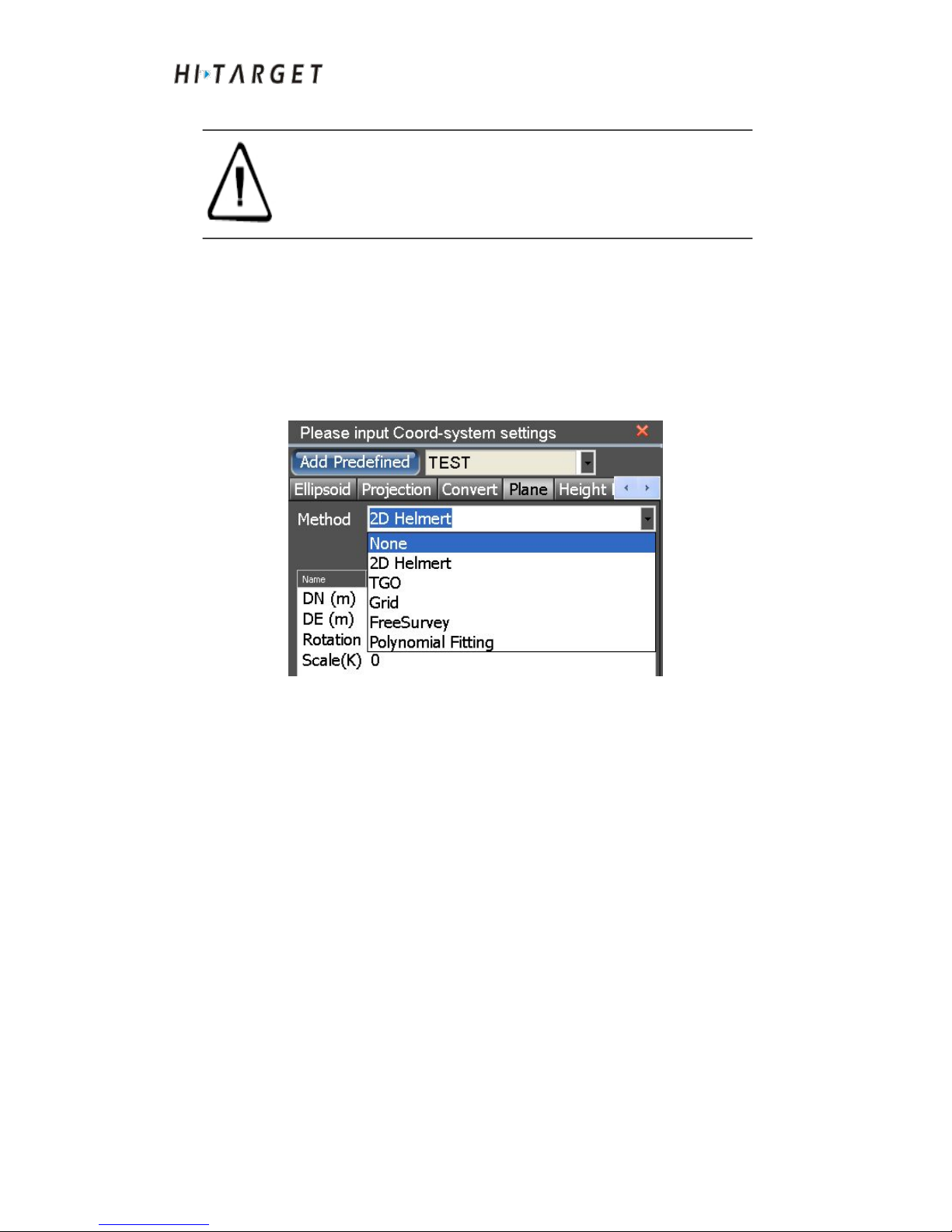
Plane transformation
Plane transformation parameters refer to transformation from
plane-coordinate system to local ellipsoid plane coordinate system after
completing source ellipsoid projection. The frequently-used conversion
methods include: 2D Helmert, TGO, Grid etc.
Figure 7-9 Plane transformation model
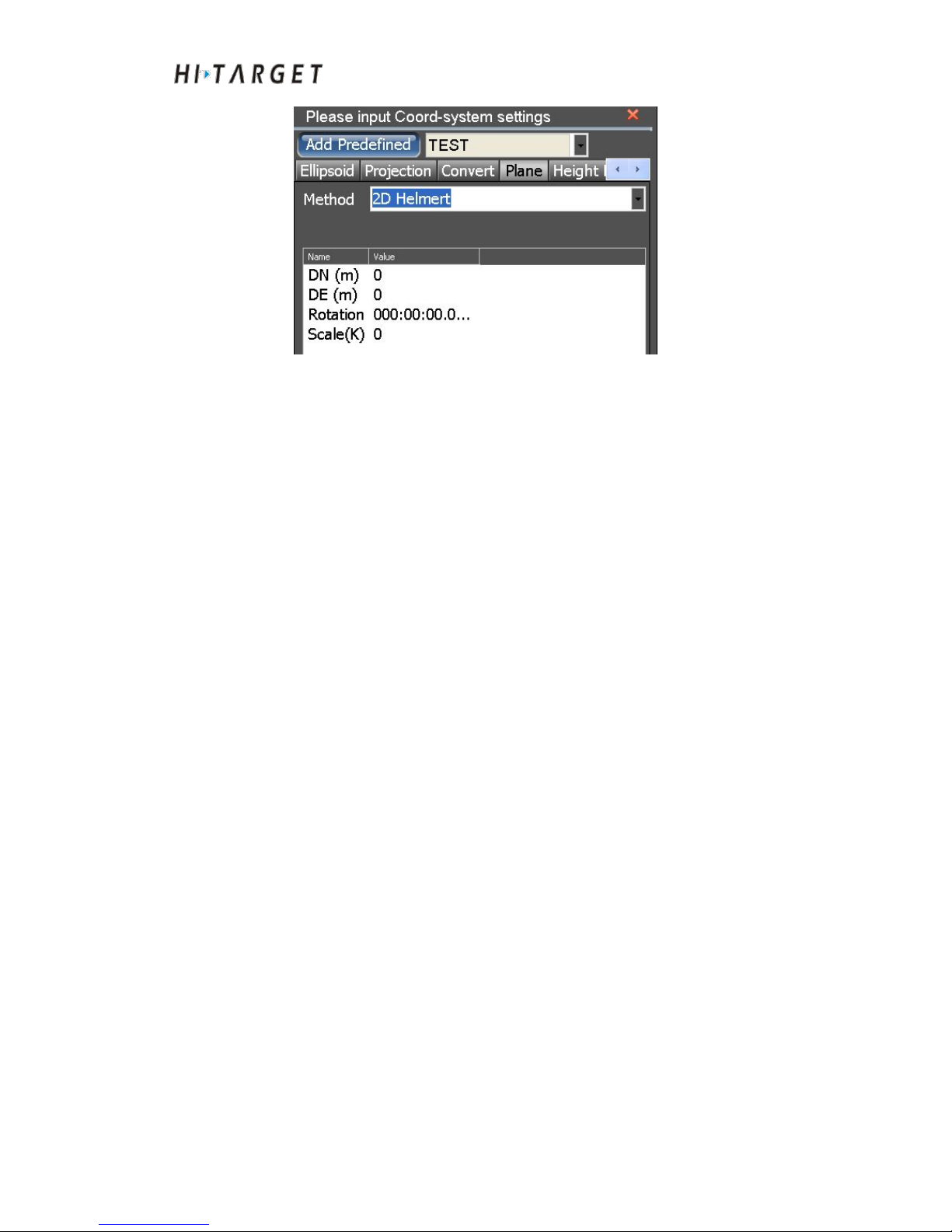
Set up parameters based on the selected model, or acquire the parameters
through Utilities, such as 2D Helmert:
Page 52
HD-MAX Echo Sounder User Guide
52
Figure 7-10 2D Helmert
Description of several commonly used plane transformation parameters
(1) 2D Helmert
Transformation, rotation and scaling parameters between two
plane-coordinate systems. It is applicable to most common engineering users.
Parametric solution can be performed from the known coordinates of two
arbitrary coordinate systems.
(2) TGO
A plane transformation method of TGO software. Comparing to 2D Helmert,
origin of coordinate north and origin of coordinate east are increased.
(3) Grid
Call-in the edited grid file format to WGS-84 coordinate transformation to
grid coordinate.
(4) FreeSurvey
It is a plane transformation method self-defined by THALES. Comparing to
four-parameter, origin of coordinate north and origin of coordinate east are
increased.
Height Fitting
Page 53
HD-MAX Echo Sounder User Guide
53
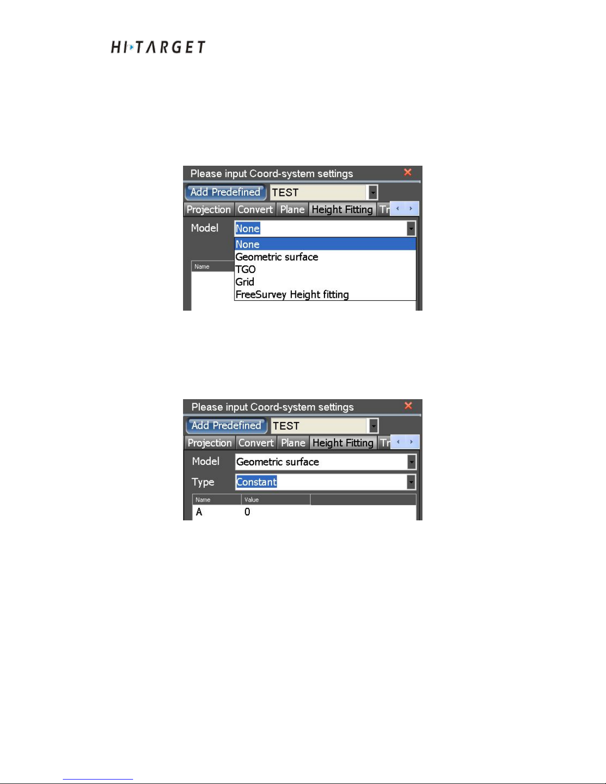
Height fitting is parameter correction to elevation fitting. Generally, it is
jointly used together with plane transformation parameters. The
frequently-used Polynomial fitting parameters include: Geometric Surface,
TGO, Grid, FreeSurvey Height fitting, and elevation fitting pattern
description etc.
Figure 7-11 Elevation fitting model
According to the fitting method selected, generally select "Constant" of "
Geometric Surface". Equations are obtained through inputting parameters or
elevation fitting algorithm of [UtilityTools], such as parameter fitting and
plane fitting:
Figure 7-12 Fixed difference correction
Description of several commonly used elevation fitting parameters:
(1) Geometric Surface
Constant correction: Take GPS measured elevation and the fixed constant as
operational elevation. Only a starting point is required.
Plane fitting: An optimal fitting plane will be generated corresponding to
height anomaly at multiple benchmarks based on three starting points. When
the plan is parallel to horizontal plane, the plane fitting is equal to fixed
difference correction.
Page 54
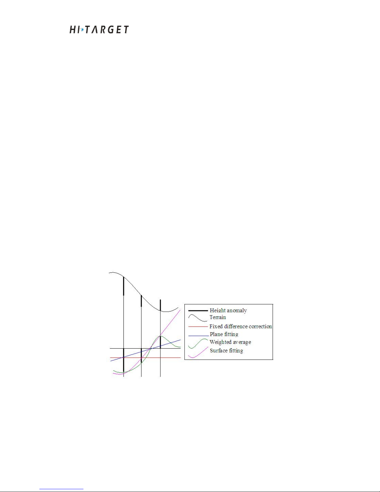
HD-MAX Echo Sounder User Guide
54
Quadratic Surface fitting: An optimal fitting paraboloid will be generated
corresponding to height anomaly at multiple benchmarks based on five
starting points. Quadratic Surface fitting is subjected to stricter start counting.
If the fitting degree is too poor, it may cause elevation correction value
divergence in the working area.
(2) TGO
Elevation transformation model of Trimble TGO software include five
parameters: constant balancing, northern slope, eastern slope, the origin of
north and the origin of east.
(3) Grid fitting
Grid fitting requires to select grid file fitting to support Trimble (ggf),
HI-TARGET (zgf), Geoid99 (bin) which can be compatible with egm-9
model. Generally, grid fitting files are great in size. Thus it may require more
time for reading. The grid fitting is rarely used in China at present. If "grid
fitting" and the other four elevation fitting methods are applied
simultaneously, perform "grid fitting" prior to other fitting methods.
(4) Free Survey Height fitting
Elevation transformation model of Trimble includes five parameters: constant
HO, northern slope, eastern slope, origin latitude and original longitude.
Figure 7-13 Simulating comparison chart of elevation fitting plane
Page 55
HD-MAX Echo Sounder User Guide
55
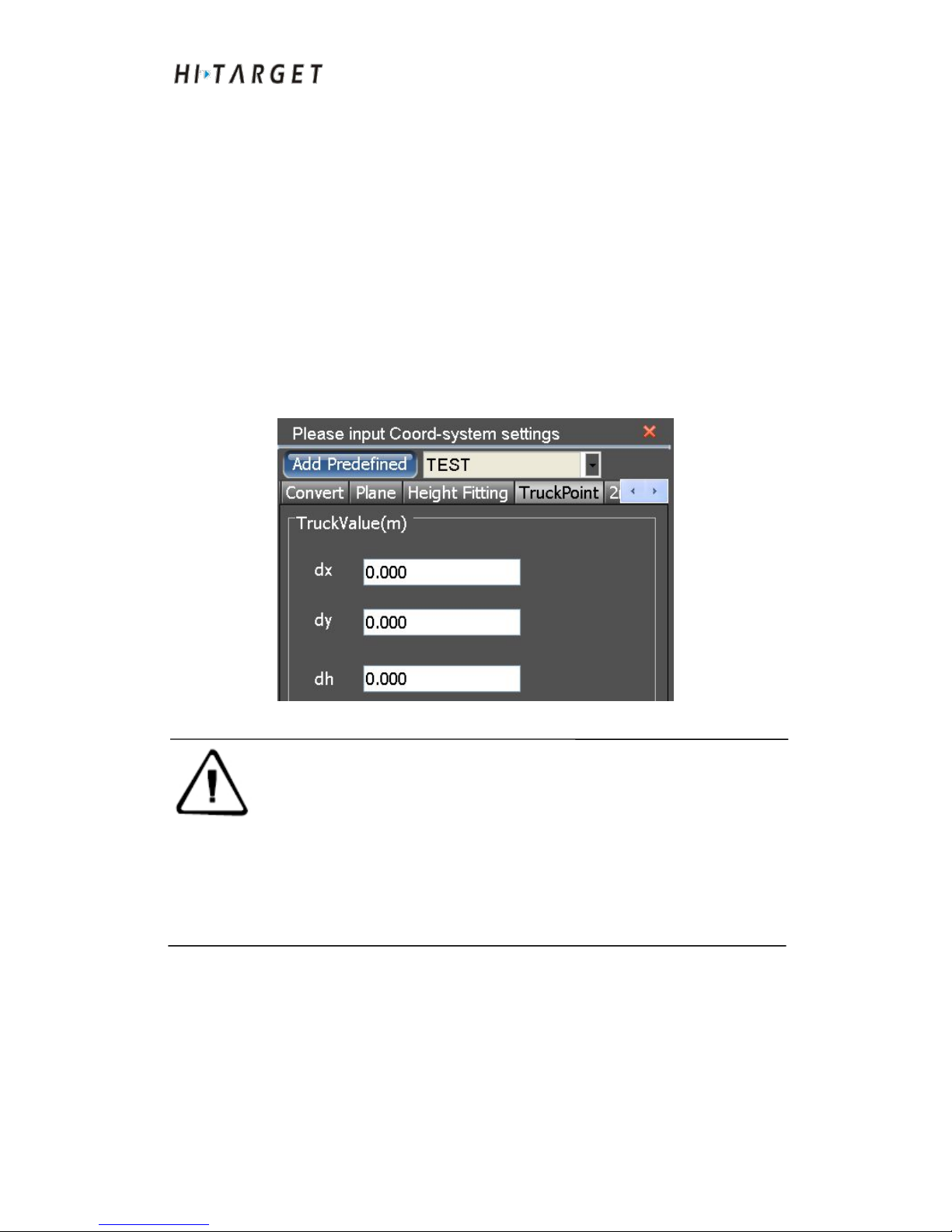
Points translation
Generally speaking, points translation (TruckPoint) only has one known
point in the working area. The GPS differential mode adopted by users is
code differential (beacon or SBAS). Besides, in case of no other translation
parameters, coordinate correction is to be performed to ensure measurement
accuracy. It is similar to fixed difference correction of the previous ocean
sounding software. The only difference is that the plus-minus signs of input
value are opposite.
dx, dy and dh can be entered as translation parameter directly. Or you can
obtain accurate translation parameter through point translation parameter
calculation tools in [UtilityTools].
Figure 7-14 Points translation
Attention: The points translation parameters of the software are
consistent with that of Hi-RTK hand book software.
However the fixed correction parameters of previous
software are different and the plus-minus signs of parameters
are opposite. For example, the fixed difference of previous
software can be input as dx, dy, dh. And for the software, the
translation parameters should be input as -dx, -dy and -dh.
Page 56
HD-MAX Echo Sounder User Guide
56
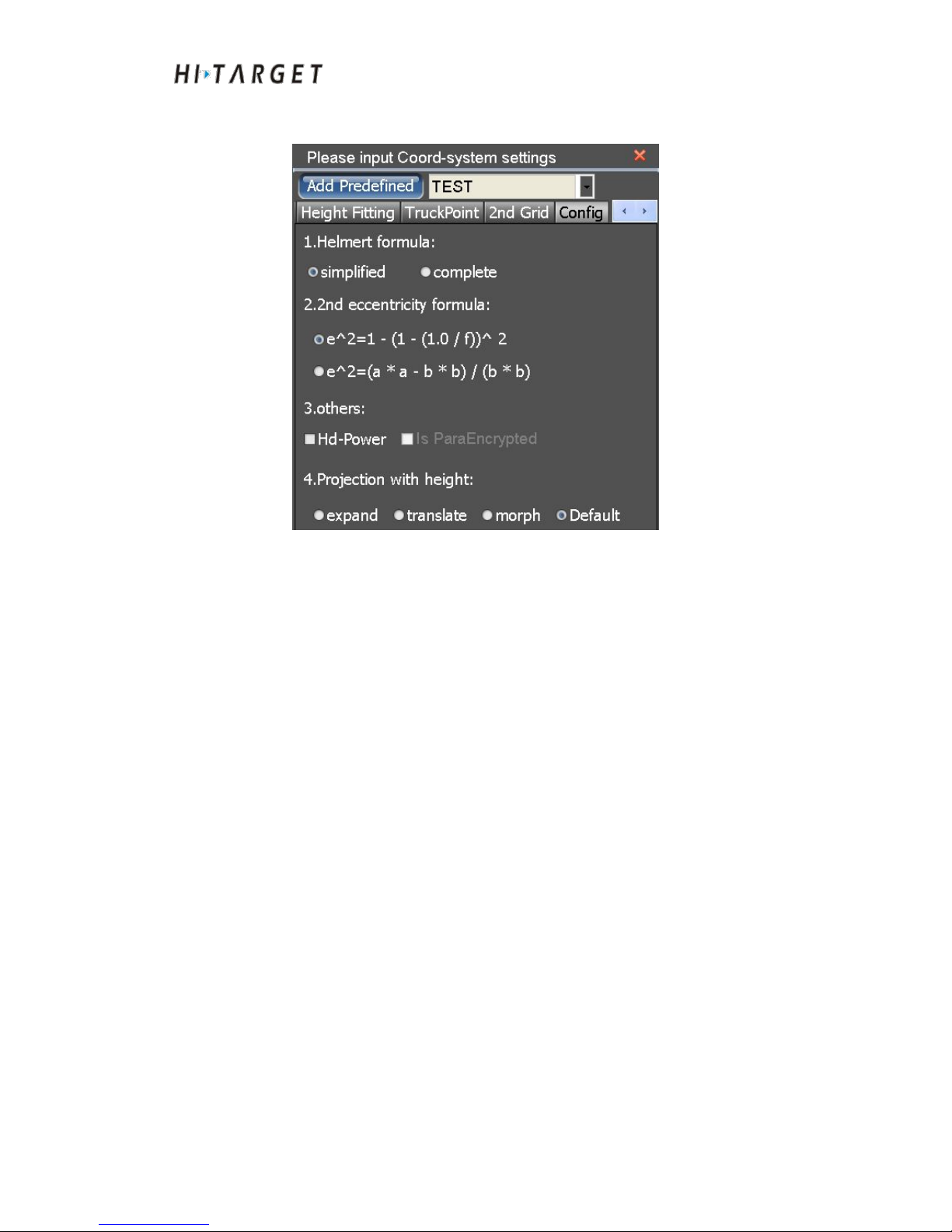
Config
Figure 7-15 Options
(1) Helmert formula. Simplified or complete version are optional. If the
rotation angle is great at ellipsoid transformation, it is suggested to take the
complete formula.
(2) "Hd-Power" is to be clicked if the solved parameters from Hd-Power
software is to be applied. Choose the simplified formula for seven-parameter.
Choose the first one for secondary eccentricity formula.
Conclusion of This Chapter
Coordinate parameter setting is an essential link for measurement setup
which determines local coordinate precision directly. Generally, there are two
types of coordinate transformation methods, seven-parameter, and
four-parameter plus elevation fitting. If transformation parameters of local
coordinate system are provided, the user only needs to input corresponding
parameter. If not, it is necessary to solve the transformation parameters.
When the number of known points is more than three, generally,
seven-parameter will be applied; when the number of known points is two,
four-parameter plus elevation fitting will be applied.
Page 57

HD-MAX Echo Sounder User Guide
57
C H A P T E R
8
Device Connection
Introduction to this Chapter
■ GPS setting
■ Auxiliary equipment settings
■ Conclusion of This Chapter
Page 58
HD-MAX Echo Sounder User Guide
58
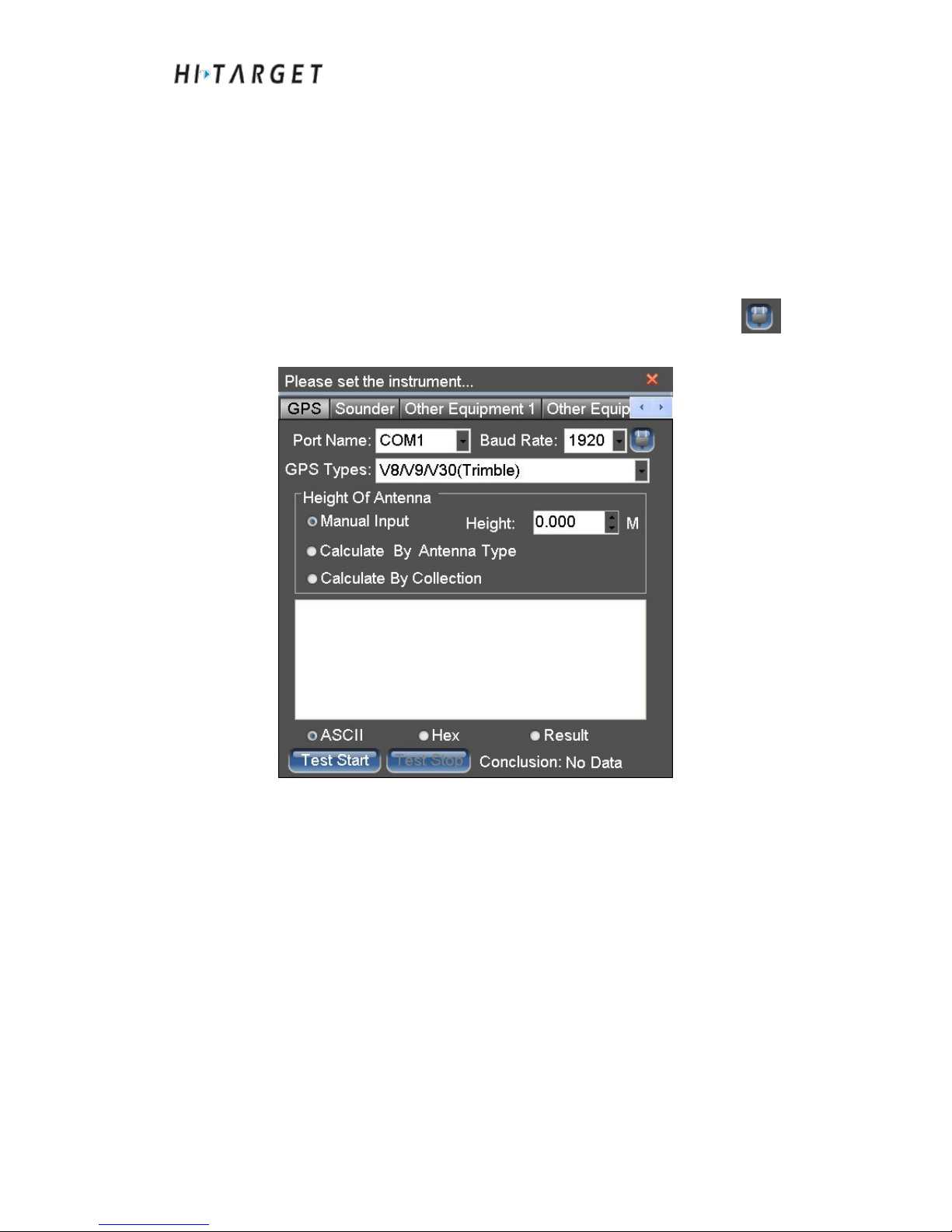
At the main menu interface, click [Equipment] to enter equipment connection
interface. The communication parameters of GPS device, Echo sounder and
subsidiary sensors can be set up. Communication tests can be performed as
well for communication parameters.
GPS Settings
Serial port setup
Select the serial port and baud rate for GPS connection. You can click
to detect baud rate automatically:
Figure 8-1 GPS serial port setup
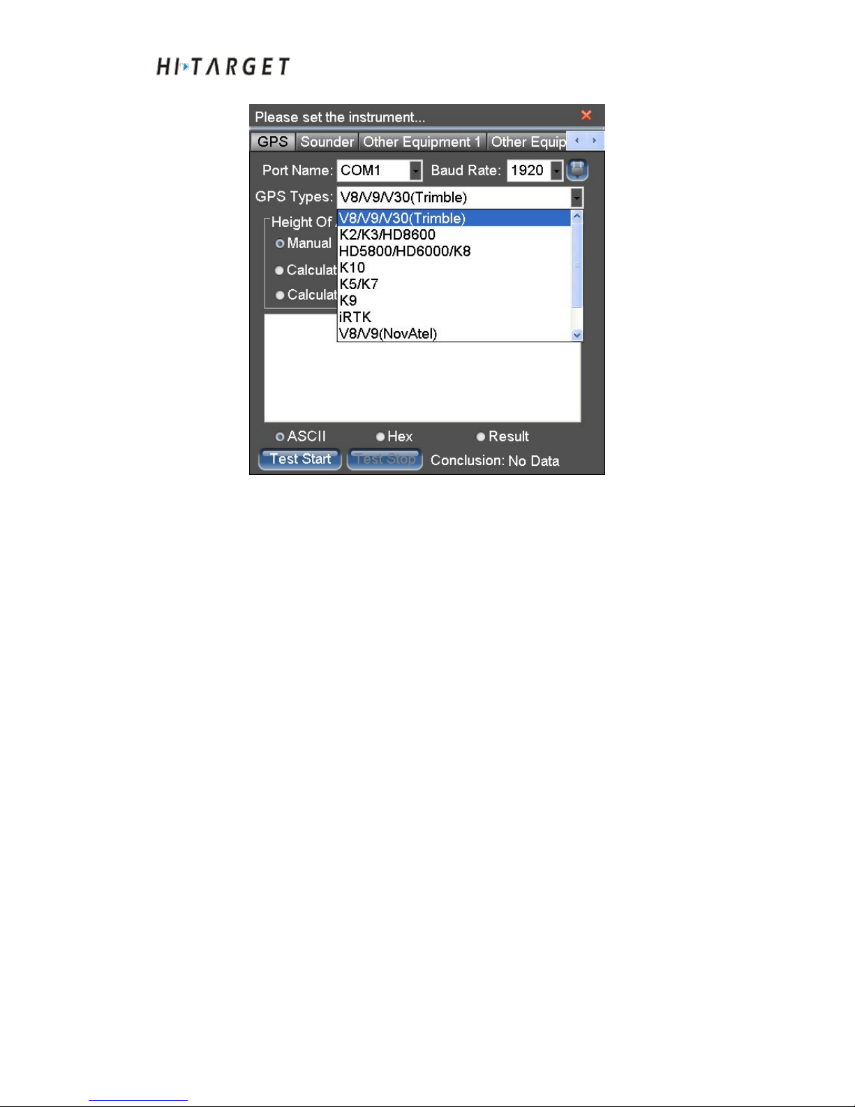
Instrument type setup
Select GPS instrument type of current connection
Page 59
HD-MAX Echo Sounder User Guide
59
Figure 8-2 GPS instrument type
If the current GPS instrument type can not be detected in the instrument type
drop-down list, please select "other models of GPS (NMEA-0183). Connect
to the GPS device following general international NMEA-0183 standard
protocol.
Page 60
HD-MAX Echo Sounder User Guide
60
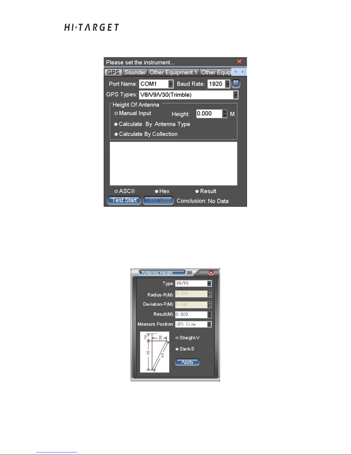
Antenna height setup
Figure 1-1
Figure 8-3 Antenna height
(1) Input antenna height: Input antenna height directly at antenna height
input box.
(2) Calculate antenna height: Select [Calculate By Antenna Type] to enter
calculation interface:
Figure 8-4 Antenna height calculation
Page 61
HD-MAX Echo Sounder User Guide
61
Select antenna type and input antenna height value. Choose type, high
antenna measuring position and radius of the antenna and the phase shift
according to different instrument model has a fixed value, if it is a custom,
users need to input. After the setup is completed, click [Application].
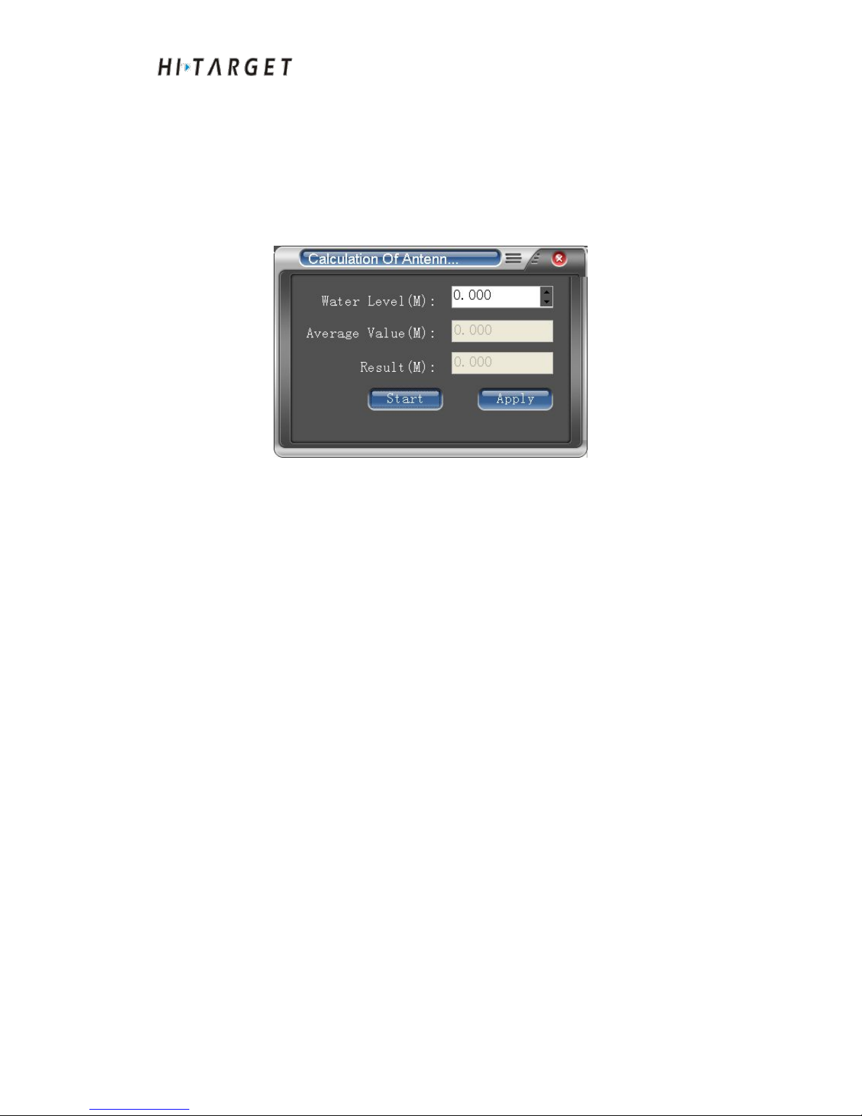
(3) Calculate antenna height automatic: Select [Calculate By Calculation]
to enter calculation interface:
Figure 8-5 Antenna height calculation
Input current water level elevation. Click [Start]. The antenna height will be
calculated automatically through smooth acquisition of ten times of effective
GPS antenna height. Click [Apply] and apply the currently calculated
antenna height to software. (It is a frequently-used method to obtain
antenna height on oceanographic instrumentation. First of all, measure the
water level elevation when the water surface is calm; secondly, try to keep
the surface elevation and GPS acquisition time in synchronization without
great time interval.)
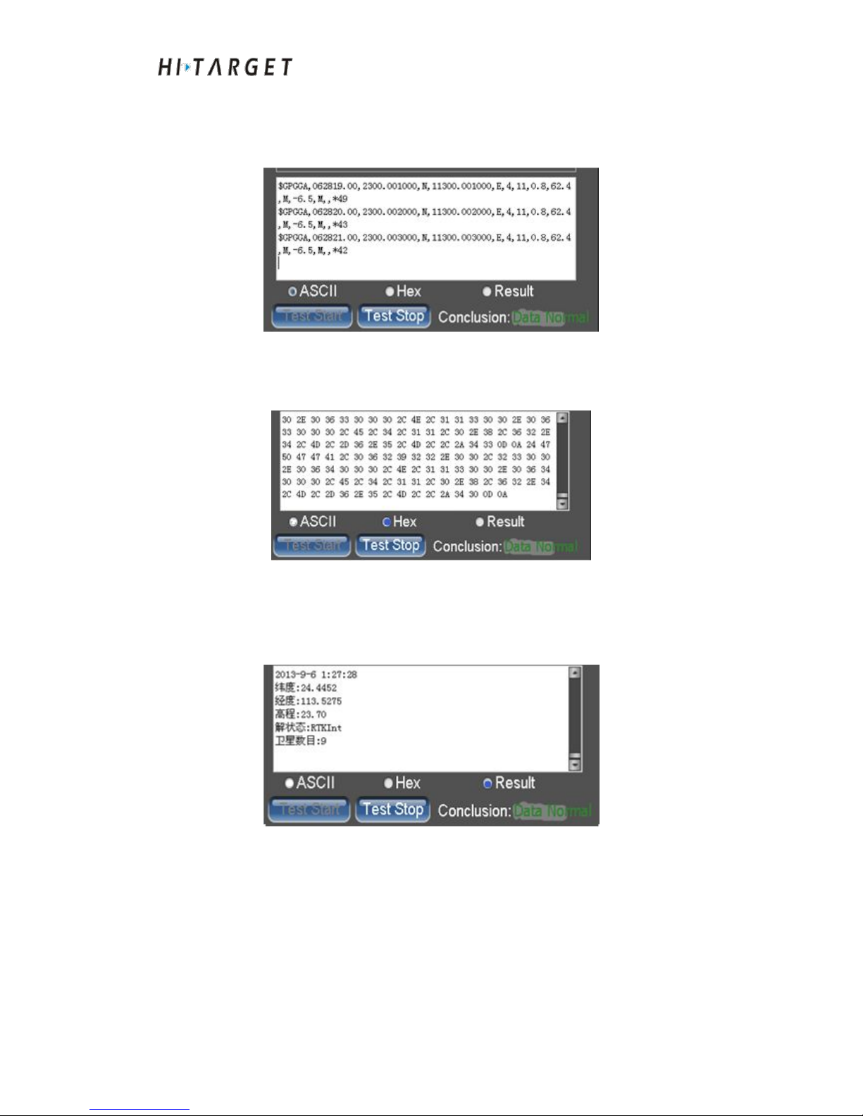
Communication test
Click [Test Start] and the serial port will be opened to receive and parse data.
The text box will display the received data and show the comprehensive
assessment of test results at lower right. There are three statuses of
[Conclusion]:
(1)No data: Serial port has not received any data.
(2)
Normal data: Correct serial port setting. Moreover, the selected
instrument type matches the connected GPS devices.
(3)
Abnormal data: Data received at the serial port. However, it can not
perform data acquisition. The possible reason is that: ① The baud rate is not
correct. ② The selected instrument type is not matching with the connected
GPS devices. ③ Date information not output
Page 62
HD-MAX Echo Sounder User Guide
62
◇Select [ASCII]. Serial data will be displayed as in character. It can check
statement information from current GPS output, such as GGA and ZDA
information:
Figure 8-6 ASCII code display
◇Select [Hex]. Serial data will display in the form of hexadecimal digits,
you can view the GPS output binary information:
Figure 8-7 Hexadecimal digit display
◇
Select [Result]. Perform data analysis for serial data and display resolved
results, including date time, longitude and latitude, elevation, computational
state, satellite data:
Figure 8-8 Results form displayed
Page 63
HD-MAX Echo Sounder User Guide
63
Auxiliary Equipment Settings
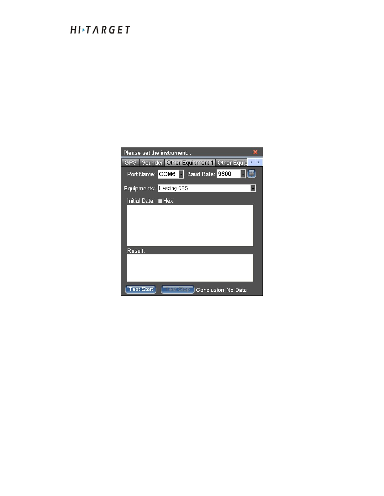
It accesses to two auxiliary equipment the setup methods of which are the
same. Click [Other Equipment] tab control. Auxiliary equipment can be
connected to gyrocompass, attitude indicator, orientation GPS and other
auxiliary measuring sensors. After setting serial port and Baud rate, select
access sensor types.
Serial port setup
Select auxiliary measurement sensors connected to serial port and baud rate:
Figure 8-9 Serial port settings of auxiliary sensors
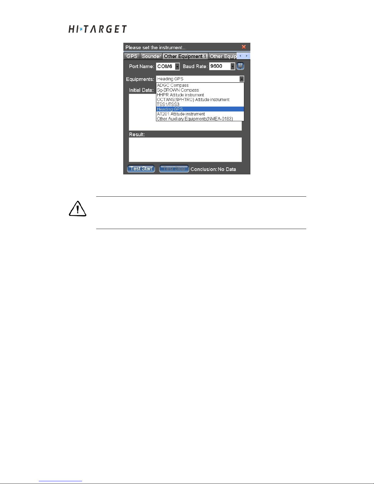
Instrument types setup
Select instrument types according to the actual access sensors or connect
sensors in TSS1/TSS3 standard communication format. Directional GPS can
get access to auxiliary sensors.
Page 64
HD-MAX Echo Sounder User Guide
64
Figure 8-10 Instrument types of auxiliary sensors
Attention: After connecting to directional GPS, the data type of directional
GPS output should be consistent with that output from
directional GPS.
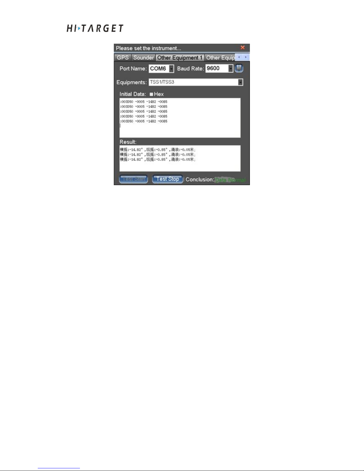
Communication test
Click [Test Start]. Open the serial port to receive and resolve data. The
original data text box will display the serial port received data. Read the
sounding information showed in the results box. Show the comprehensive
assessment of test results at lower right. There are three status of
[Conclusion]:
(4)No data: Serial port not received any data.
(5)
Normal data: Correct serial port setting. Moreover, the selected
instrument type is matching with the connected Echo sounder device.
(6)Abnormal data: Data received at the serial port. However, the data is not
correct. The possible reasons are: ① The baud rate is not correct. ② The
selected instrument type is not matching with the connected depth sounding
devices.
Page 65
HD-MAX Echo Sounder User Guide
65
Figure 8-11 Auxiliary sensor communication test
Conclusion of This Chapter
Instrument connection parameters mainly include serial port, Baud rate and
instrument type. Based on serial port raw data and resolved results displayed,
the incorrect parameter setting or existing problems of serial port can be
determined properly. The auxiliary sensors are to avoid influence on
measuring results caused by hull pitch and swing thus to improve the
accuracy of data acquisition. The auxiliary sensors include gyrocompass,
attitude indicator, directional GPS et. al..
Page 66

HD-MAX Echo Sounder User Guide
66
C H A P T E R
9
Ship Design
Introduction to this Chapter
■ Ship Design
■ Conclusion of This Chapter
Page 67
HD-MAX Echo Sounder User Guide
67
Ship Design
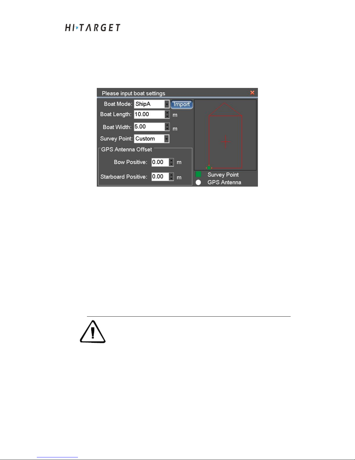
At the software main menu interface, click [BoatShape] to enter the design
interface. The outer contour of the ship can be designed. The instrument
installation parameters can be setup.
Figure 9-1 Ship Design
Design outer contour of the ship: Select existing ship model or import hull
outline data in DXF format. Set up the length and width of the ship. The
software will perform self-adapting calculation according to hull model and
width to generate outer contour of the ship. The outside contour line of the
hull will affect visual effects of ship but without any effects on acquisition
data.
Instrument installation parameters setup: Select installation position of
transducer. [Left Side], [Right Side] or [Custom] are optional. The
self-defined settings will select green squares to move forward as shown in
the schematic diagram. Set the deviation between GPS antenna
position to transducer. Instrument installation parameters will affect the
measured result data thus they should be measured accurately.
Attention: At positions near to bow, there are more waves and
bubbles which will generate great interference on sounding of Echo
sounder. While at positions near to the stern, the waves and bubbles
generated by propeller will generate great interference on sounding
of Echo sounder as well. Therefore, the optimal installation position
of transducer is at the middle section of the ship. Generally, the
transducer is subordinate to stroke-side or starboard. If the actual
installation location is at the other position, select [Left Side] or
[Right Side] if it is installed at a position close to stroke-side or
starboard correspondingly.
Page 68

HD-MAX Echo Sounder User Guide
68
Conclusion of This Chapter
For ship design, ship model as well as the width of the hull will not affect the
measuring result data. Users only need to input approximate values of hull
length and width. (Only the deviation parameter of GPS antenna position and
transducer position will affect measuring results. The parameters need
accurate measurement.)
Page 69

HD-MAX Echo Sounder User Guide
69
Plan line design
Introduction to this Chapter
■ Plan line preparation
■ Plan line edit
■ Plan line routing
■ Plan line import
■ Auxiliary functions
■ Conclusion of This Chapter
CHAPTER
10
Page 70
HD-MAX Echo Sounder User Guide
70
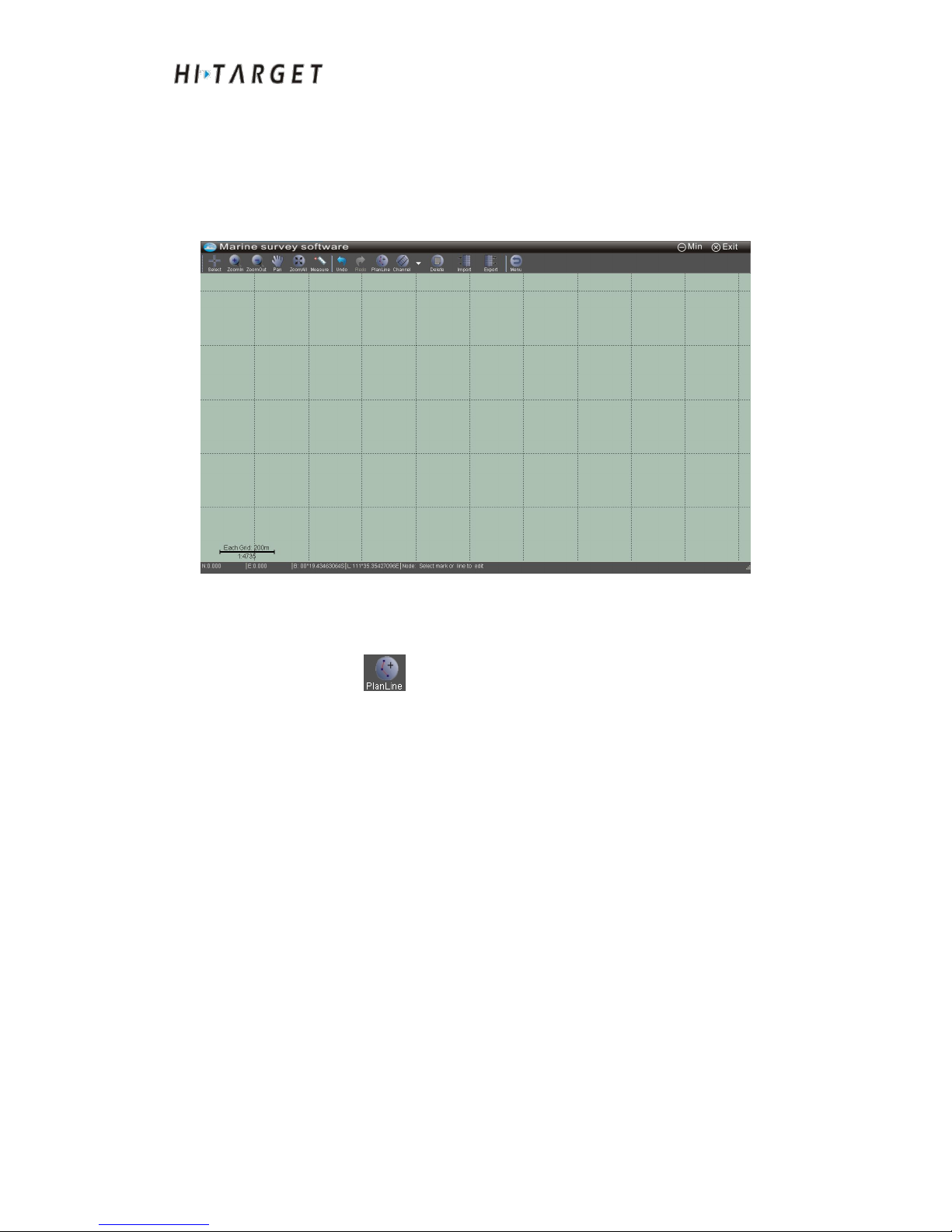
At software main menu interface, click [PlanLines] to enter plan line design
interface. Draw the plan line with the mouse or coordinate. It supports plan
line edit as well. Rapid routing can be realized by channel routing, regional
routing, parallel routing, vertical routing and fan routing. Plan line data in
DXF format can be imported.
Figure 10-1 Main interface of plan line design
Plan line preparation
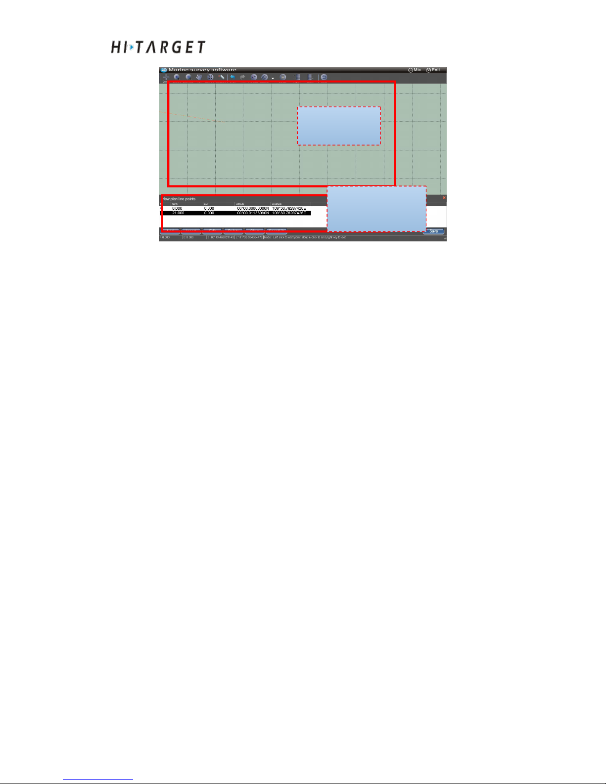
Click [PlanLine] to enter plan line drawing mode. Click the screen
with a mouse directly to draw point by point. And also you can draw the plan
line by increasing coordinates into the coordinates list. Mouse drawing and
coordinates drawing can be performed simultaneously. Click [Save] to
save the current plan line and start to draw the next plan line. During the
processing of drawing, it can perform coordinates increasing, inserting,
editing, deletion, empty and other operations.
Page 71
HD-MAX Echo Sounder User Guide
71
Figure 10-2 Plan line drawing
Mouse drawing
Under the mode of plan line drawing, the mouse icon will turn red cross. You
can click left key of mouse to determine the vertex position of plan line. The
coordinates of the position clicked by the mouse will be automatically added
to the coordinates list. Double click the left mouse button to complete the
current plan line and start to draw the next plan line. Click the right mouse
button to complete the current plan line and exist the mode of plan line
drawing.
Coordinates drawing
Plan line vertices can be increased by pressing [Add] and [Insert] in the
coordinates list of coordinates drawing area. The coordinate value of a
certain coordinate point can be modified by pressing [Edit]. The plan line
vertices can be deleted by pressing [Delete] and [Clear] key.
[Add]: To add a coordinate point in coordinates list.
[Insert] To insert a coordinate point before the selected line in coordinates
list.
[Edit] To modify the selected coordinate point in coordinates list.
[Delete] To delete the selected coordinate point in coordinates list.
[Clear] To remove all coordinate points in coordinates list.
[CoordLib]: Direct reference points in coordinates library.
Mouse
drawing area
Coordinates edition
area
Page 72
HD-MAX Echo Sounder User Guide
72
Coordinates input box
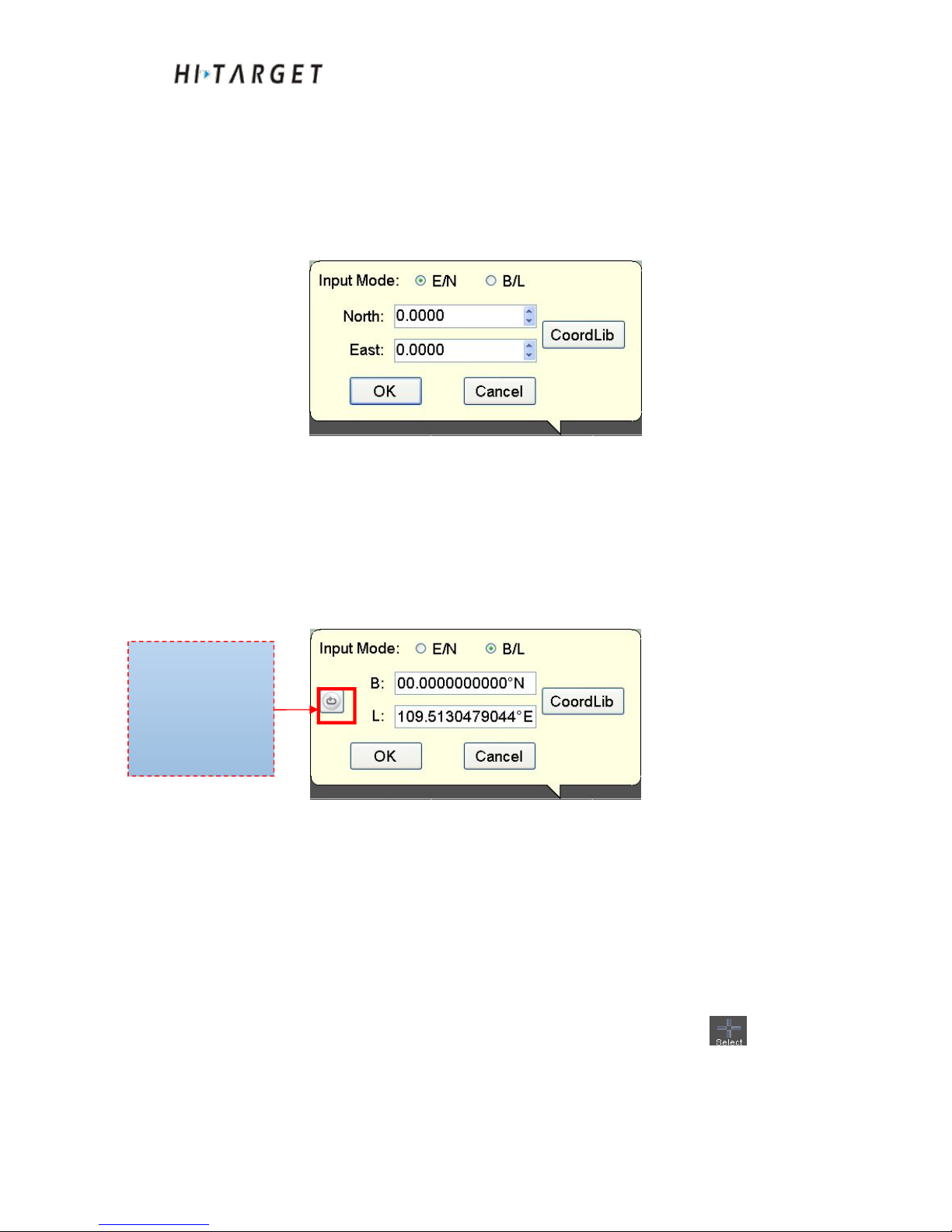
Before coordinates input or coordinates editing, please refer to Chapter IV.
Input correct coordinate transformation parameters. There are two types of
coordinate input methods optional:
(1) Plane coordinates input
Figure 10-3 Plane coordinates input box
The coordinate system of plane coordinates is the local coordinate system.
After click [OK], the system will convert plane coordinates to WGS84
latitude and longitude and store according to the parameters setting of
[Geodetic]. Or you can cite directly from the coordinate library.
(2) Latitude and longitude input mode
Figure 10-4 Latitude and longitude input box
The input latitude and longitude is as in the form of WGS84. The input mode
can be switched among degree, degree of minutes and degree of seconds. "N"
refers to northern latitude, "S" as southern latitude, "E" as east longitude and
"W" as west longitude.
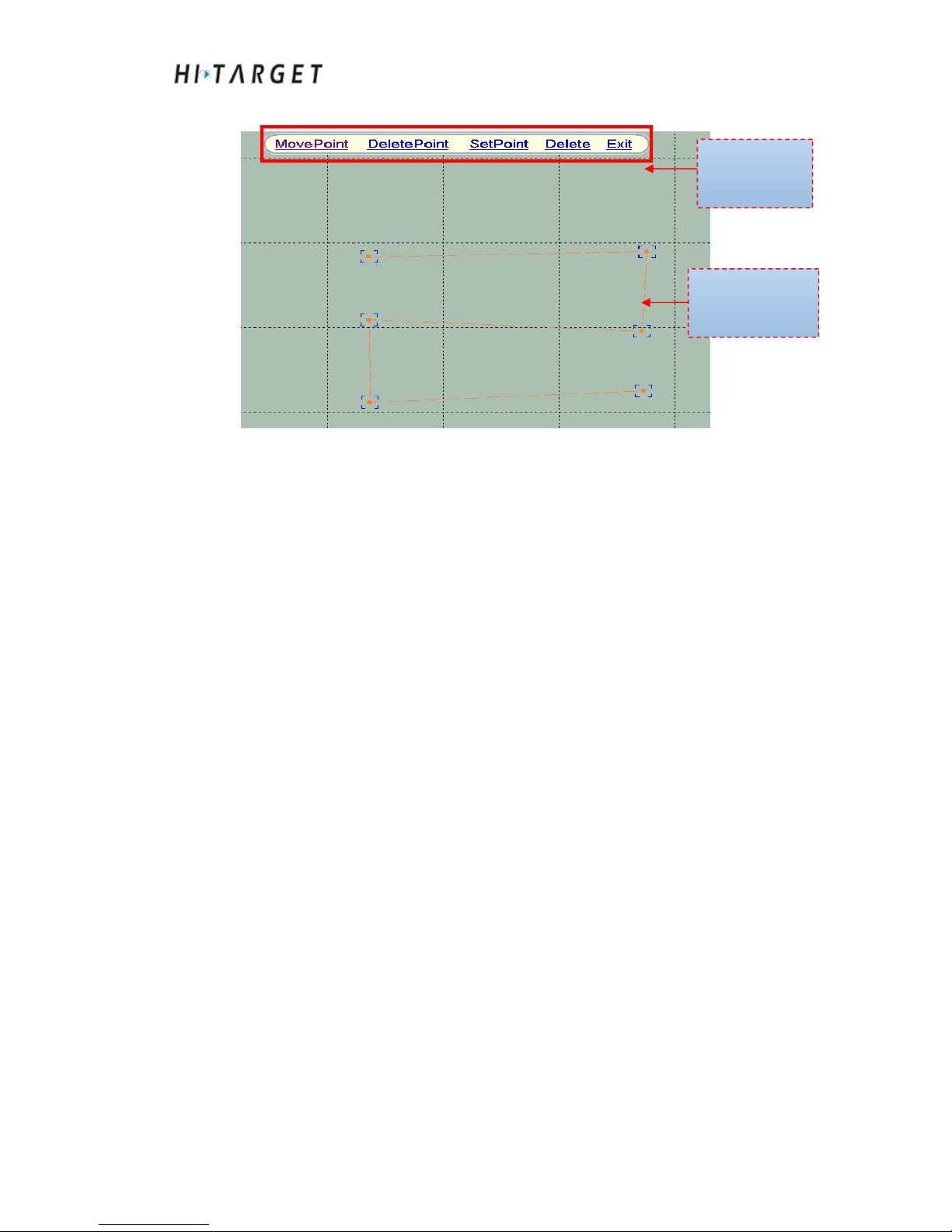
Plan line edit
Plan line edit mainly includes removing, deleting and modifying vertex
coordinates as well as deleting plan line. First of all, click [Select] , and
then select a plan line to enter the plan line edit mode. You can edit the
toolbar for plan line edit. After that, click [Exit] or right mouse button to exit
Input mode switch
1. °
2. °′
3. °′″
Page 73
HD-MAX Echo Sounder User Guide
73
edit mode.
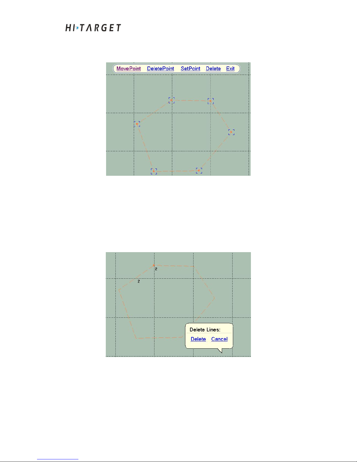
Figure 10-5 Plan line edit
Edit plan line vertex
After selecting a plan line with selection tool, you can perform the following
operations as below:
Dragging the vertices with the mouse: Click [MovePoint] and then perform
vertex dragging with a mouse.
Mouse click and delete vertices: Click [DeletePoint] and click the vertex to
be deleted with the left button of the mouse.
Modify vertex coordinates: Click [SetPoint] and then click the vertex to be
modified with the left button of the mouse. A coordinate input box will pop
up. Input the new coordinate value in the input box. Click [OK] to complete
modification to the coordinate.
Plan line deletion
There are three methods can be selected from: Single selection deletion, box
selection deletion and scope deletion.
(1)Single selection deletion
Toolbar edit
Planed route
edit
Page 74
HD-MAX Echo Sounder User Guide
74
To select a plan line with the selection tool and select [delete] in the edit
toolbar.
Figure 10-6 Single selection deletion
(2)Box selection deletion
Select multiple plan lines from selection tool boxes. A bubble box of plan
lines will pop up. Click [Delete] to delete the selected plan line (orange
display).
Figure 10-7 Box selection deletion
(3)Scope deletion
Page 75
HD-MAX Echo Sounder User Guide
75
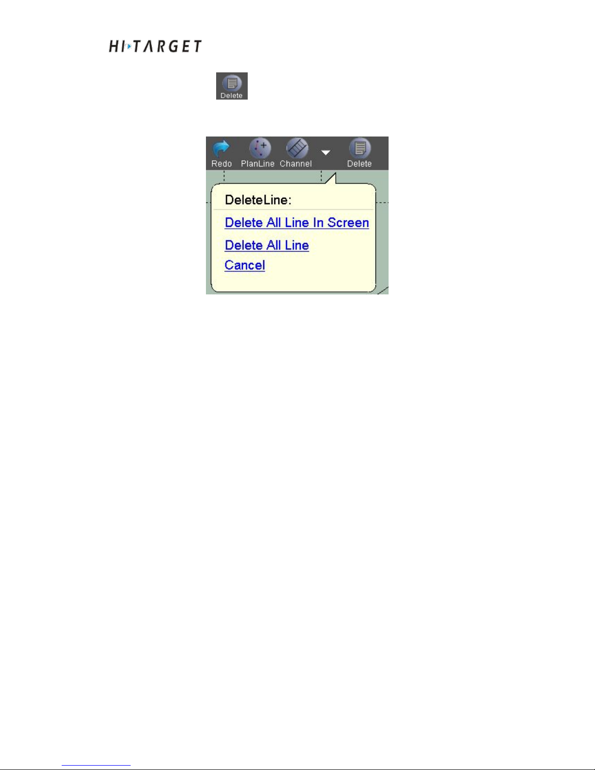
Click [Delete] in the menu bar. The bubble box of [DeletionLine]
can delete the plan line in a wide range.
Figure 10-8 Range deletion
To delete all lines in the screen: Delete all plan lines in the current scope,
including certain plan lines displayed in the screen range.
To delete all lines: Delete all plan lines.
Plan line routing
Plan line routing can generate a large number of plan lines conveniently and
rapidly. The frequently-used routing models include: "channel routing", "area
routing", "vertical routing", "parallel routing" and "Sector routing". Users can
select appropriate routing models to perform rapid routing according to the
requirements of actual measured area.
Page 76
HD-MAX Echo Sounder User Guide
76
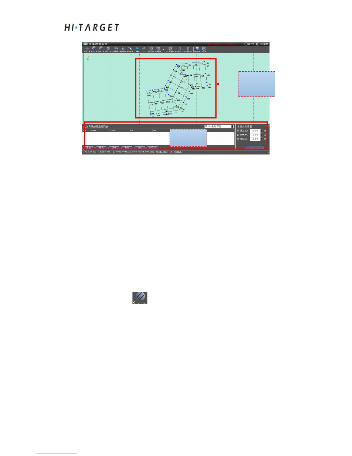
Figure 10-9 Plan line routing
Mouse/coordinate drawing: Draw a baseline with the mouse or coordinate
(The method of mapping method and line drawing method are the same).
Choose an existing line with the mouse: Choose an existing plan line and add
all vertex coordinates to baseline coordinates list. Editing the coordinate
points in the list will not change the selected plan line.
Generation and storage: The system will generate plan line according to the
baseline and routing parameters, save the generated plan line and start the
new plan line routing.
Channel routing
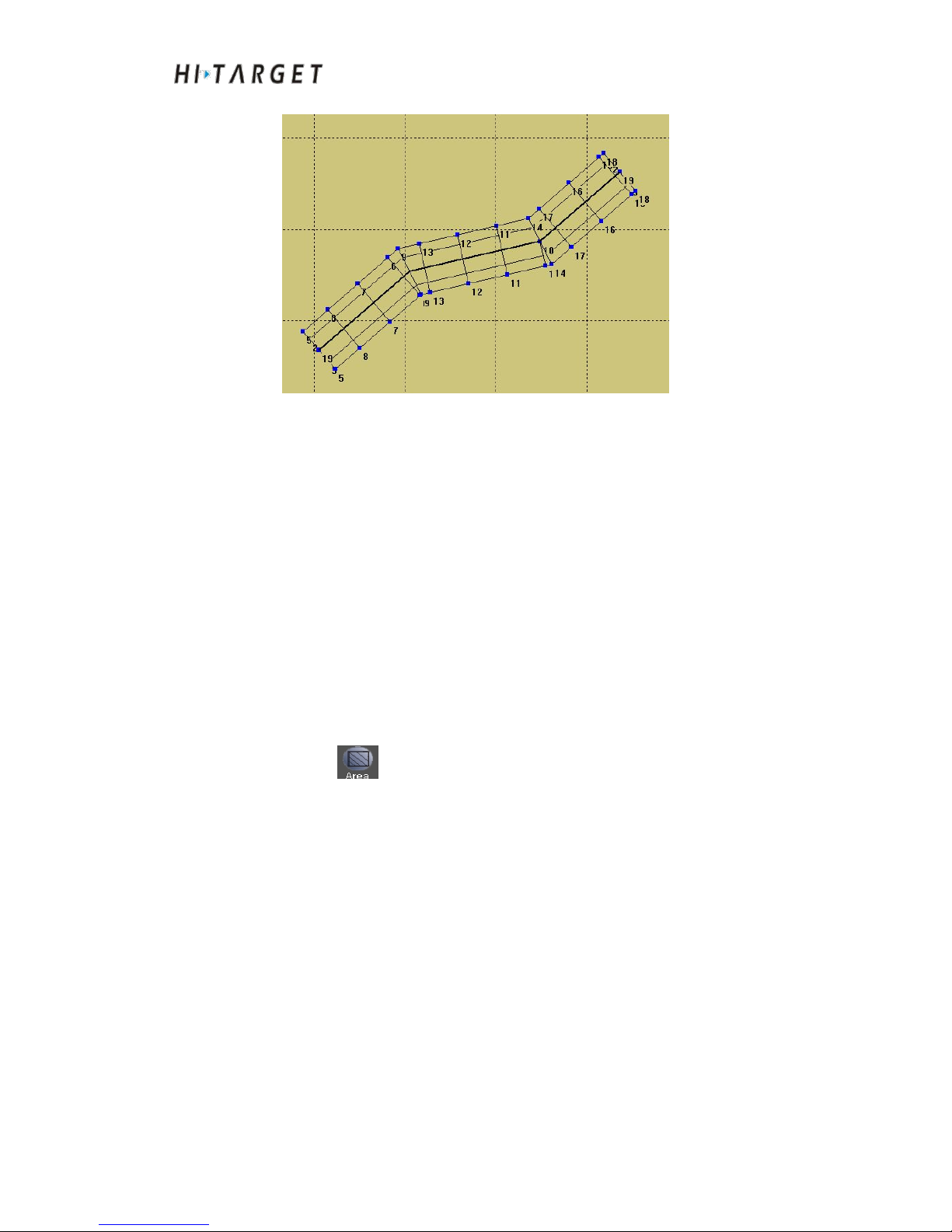
Click [Channel] in the toolbar. Draw a base line with the mouse or
coordinate or select an existing plan line as axle wire of the channel. Set
routing parameters and click [Create and save]. The system will generate
channel plan line and start a new channel routing.
Layout
results
Layout
parameters
Page 77
HD-MAX Echo Sounder User Guide
77
Figure 10-10 Channel routing
Channel width: The passable width, channel width ratio is wider than the
survey line width.
Survey line width: In waterway survey, perform routing vertical to the
channel axis as well as the width of the plan line.
Routing interval: In waterway survey, perform routing vertical to the channel
axis as well as the space between the plan lines.
Area routing
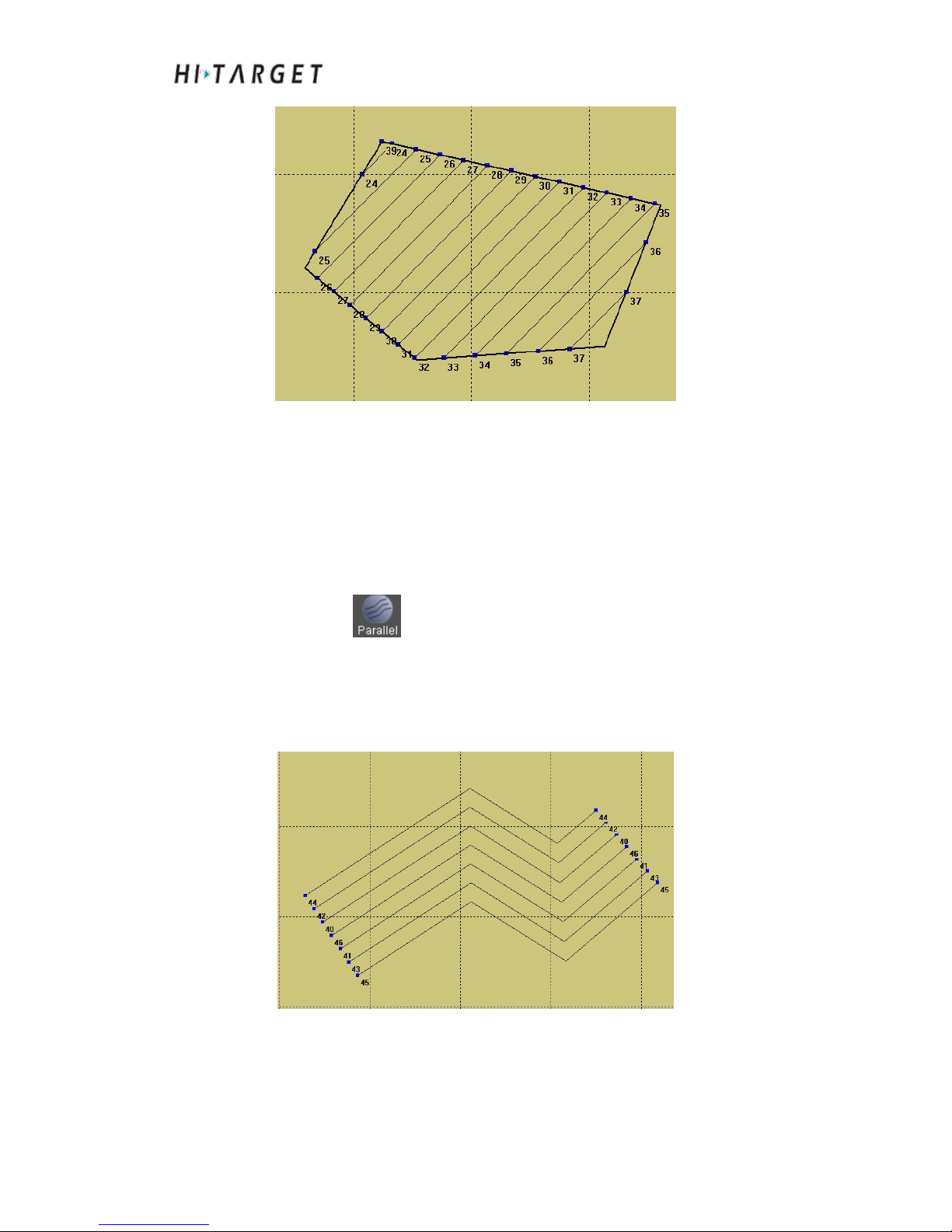
Click [Area] in the toolbar. Draw a base line with the mouse or
coordinate or select an existing plan line as the border of the area. Set routing
parameters and click [Create and save]. The system will generate channel
plan line and start a new area routing.
Page 78
HD-MAX Echo Sounder User Guide
78
Figure 10-11 Area routing
Routing direction: The included angle between plan line direction and the
true north direction.
Layout interval: Distance between the plan lines generated.
Parallel routing
Click [Parallel] in the toolbar. Draw a base line with the mouse or
coordinate or select an existing plan line as start line. Set routing parameters
and click [Create and save]. The system will generate channel plan line and
start parallel routing.
Figure 10-12 Parallel routing
Page 79
HD-MAX Echo Sounder User Guide
79
Layout interval: Distance between the plan line generated.
Line number at the left side: The number of plan lines at the left side of start
line (namely baseline).
Line number at the right side: The number of plan lines at the right side of
start line (namely baseline).
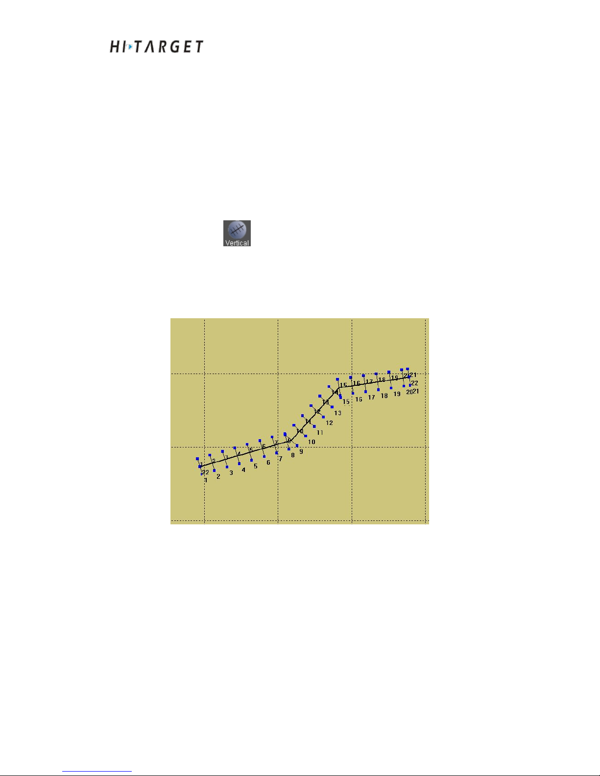
Vertical routing
Click [Vertical] in the toolbar. Draw a base line with the mouse or
coordinate or select an existing plan line as start line. Set routing parameters
and click [Create and save]. The system will generate channel plan line and
start vertical routing.
Figure 10-13 Vertical routing
Layout interval: Distance between the plan line generated.
Line length at the left side: The length of plan line at left side of baseline.
Line length at the right side: The length of plan line at right side of baseline.
Page 80
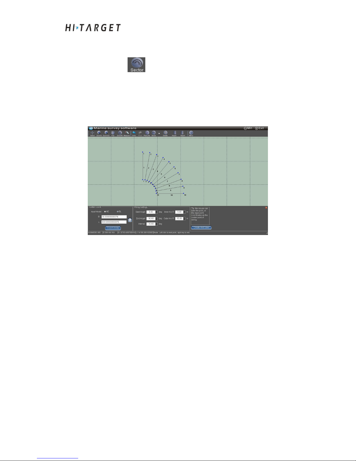
HD-MAX Echo Sounder User Guide
80
Circular sector routing
Click [Sector] in the toolbar. Select a point with the mouse or input a
coordinate point as the central point of circular sector. Set routing parameters
and click [Create and save]. The system will generate channel plan line
according to the baseline as well as the setup parameters. And then start a
new circular sector routing.
Figure 10-14 Circular sector routing
Center Coord: The coordinate of the central point of circular sector. It can be
selected with a mouse or input plane coordinates or WGS84 longitude and
latitude.
Start angle: The included angle between the first plan line and the true north
direction.
End angle: The included angle between the first plan line and the true north
direction.
Interval angle: The angle-interval between planned routes.
Inner arc radius: Radius of inner arc
Outer arc radius: Outer arc radius
Page 81

HD-MAX Echo Sounder User Guide
81
Plan line import-export
Click the [Import] and a dialog box will pop up. Select the imported
DXF file and click [Open]. After the planned routes are imported to the
system, they can be edited.
Click the [Export] and a dialog box will pop up. Select the route and
export DXF file and click current planned routes.
Shortcut key
(1) Upper, lower, left and right buttons
When draw graphics with a mouse, press upper, lower, left and right buttons
to move the background image all around.
(2) Middle mouse button
Slide the middle mouse button pulley. Set mouse position as the center and
graph zooming. Press the mouse middle button to perform Pan View
。
(3) Right mouse button
While performing zoom in, zoom out, pan view, planned routes drawing,
editing and layout, press right mouse button to exit those operations
immediately.
Other functions
(1) Can perform chart query and chart management. There is no separate
introduction available since it is the same with measuring interface.
(2) Distance measuring angle. There is no separate introduction available
since it is the same with measuring interface.
(3) Undo and Recovery function
Click Undo or Recovery to undo the last operation. And click
Recovery to resume the cancelled operation as shown in the Figure.
Page 82

HD-MAX Echo Sounder User Guide
82
Conclusion of This Chapter
Planned route design is an important preparation of bathymetric survey.
Through reasonable planned route layout, the measured data can be more
even, reducing the occurrence of repeated measurements and missing thus to
effectively improve the measurement efficiency. The software supports
electronic chart display. Users can import the electronic chart of the
measuring area into the system. Take the electronic chart as a reference. It is
more easy and convenient to perform planned routes arrangement.
Page 83

HD-MAX Echo Sounder User Guide
83
Electronic Chart
Introduction to this Chapter
■ Sea Chart Import
■ Sea Chart Display
■ Sea Chart Inquire
■ Conclusion of This Chapter
CHAPTER
11
Page 84
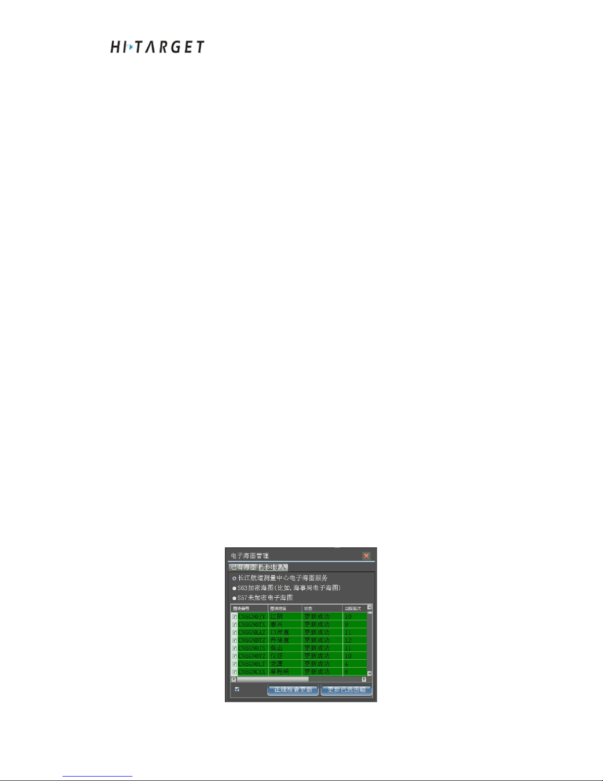
HD-MAX Echo Sounder User Guide
84
Sea chart is a geographical map presenting marine and ocean space. It is an
indispensable reference basis for sailing. Main contents include: shore,
islands, reefs, sounding, beacons and radio navigation etc.. At the software
main menu interface, click [Charts] to enter electronic chart management
interface. The CWB electronic chart, S63 encrypted electronic chart, S57
unencrypted electronic chart can be imported. Can perform display, hidden,
deletion and other operations on the imported electronic chart.
Sea Chart Import
The system has passed IHO certification. The chart data from the data
providers of other countries can be imported. In addition, the on line
electronic chart data provided by Changjiang Waterway Survey Center can
be online imported. The successfully imported electronic chart will be
displayed in the electronic chart list. And display in background graphics
under the module of [Planned routes design] and [Marine surveying].
CWB electronic chart
CWB electronic charts are those issued on the website of Changjiang
Waterway Bureau. They need to be connected to the Internet. CWB
electronic charts almost cover the whole Yangtze River Basin. Select
"Electronic Chart Services of Changjiang Waterway Survey Center". Click
[Online upgrading] to obtain the issued information of electronic chart. The
system will display the electronic charts requiring to be updated. Click the
electronic charts requiring to be updated and click [Updated the selected
charts]. The system will automatic download the clicked electronic chart data
and import to the system.
Page 85
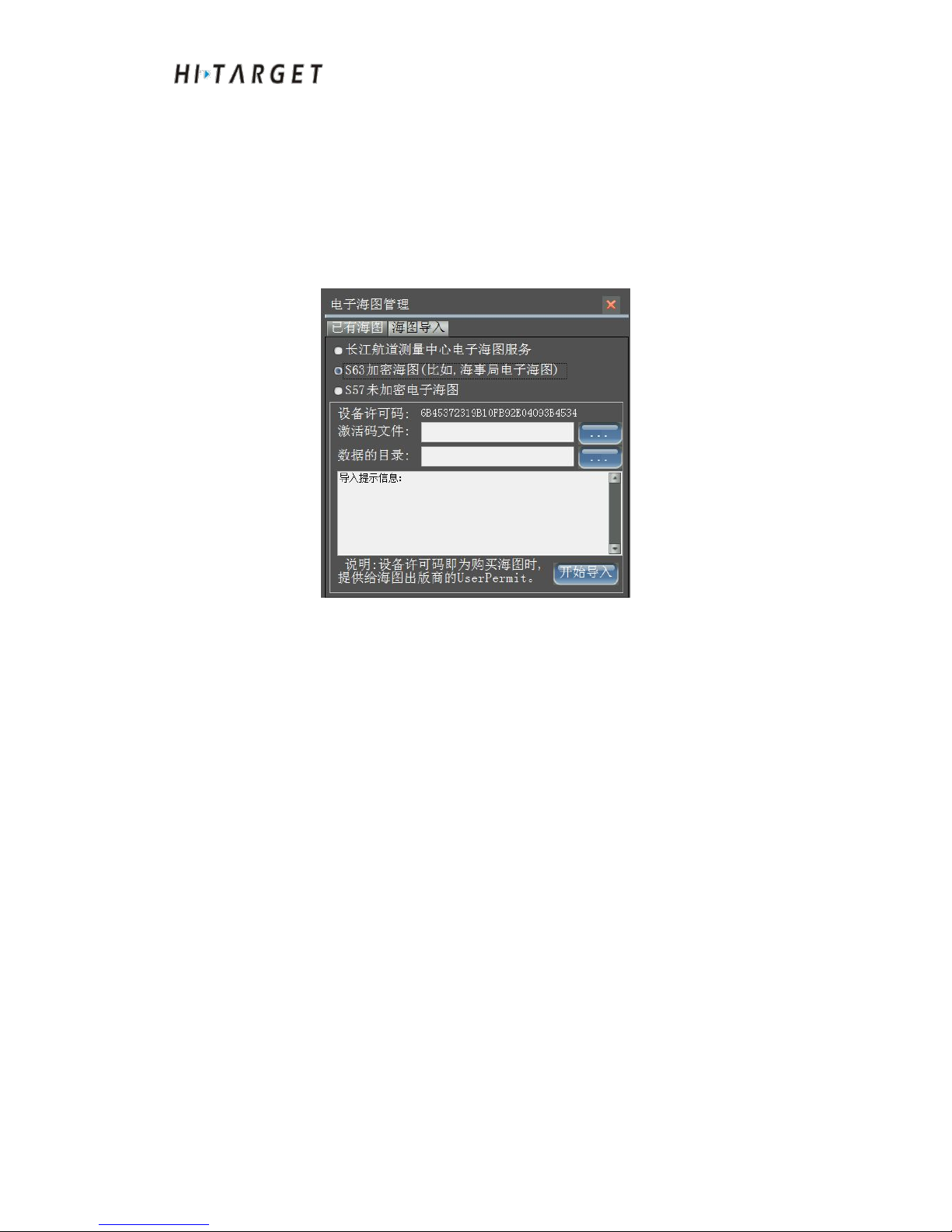
HD-MAX Echo Sounder User Guide
85
Figure 11-1 CWB electronic charts
Encrypted chart
Encrypted charts refer to purchasing electronic charts from formal channels
to the electronic chart data provider. The data format is S63. After selecting
activated code files and S63 data directory, click [Start importing]. The
system will automatically import electronic charts.
Figure 11-2 Encrypted electronic charts
Equipment license code: When users buy chart, they need to provide the
unique identification document of the equipment to electronic chart data
provider.
Activated code files: After the users purchasing electronic charts, the
electronic chart data provider will provide chart authorization documents,
which include decryption key information of the electronic chart.
Data directory: Chart version information and encrypted electronic chart are
saved under the folder path of S63 chart data.
Unencrypted chart
Unencrypted chart refers to unencrypted electronic chart obtained from grey
channels with the data format of S57.
Page 86
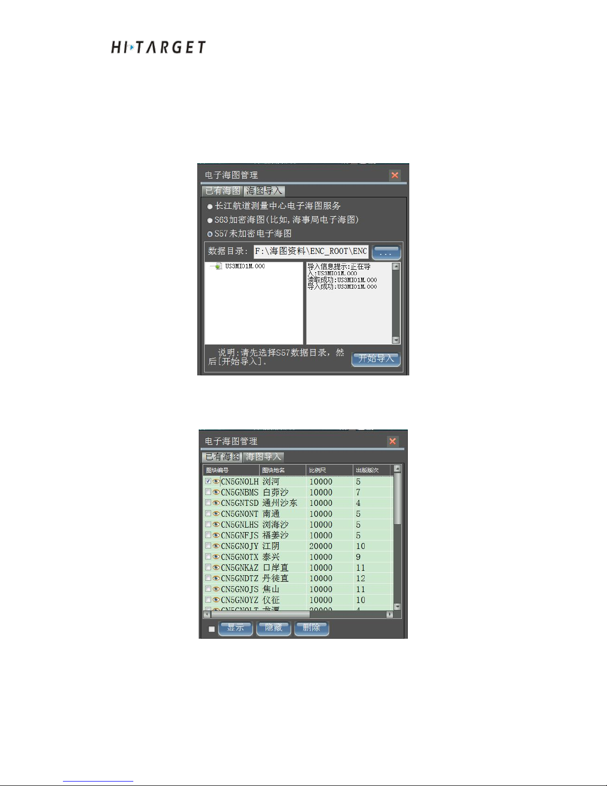
HD-MAX Echo Sounder User Guide
86
Select data storage directory of S57. The software will identify S57 files and
display them in tree form in the left list. Click to import the data and the
software will automatically import the data to the system and will export the
imported message in the text box at the right side.
Figure 11-3 Unencrypted electronic chart
Existing electronic chart
Figure 11.1.4 Existing electronic chart
The basic information of imported electronic chart at "Existing electronic
chart", including electronic chart No., block geographical names, scale,
Page 87
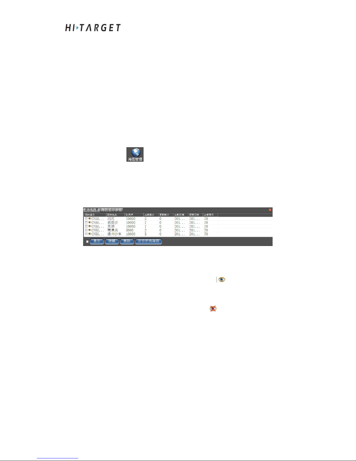
HD-MAX Echo Sounder User Guide
87
published edition, updated edition, date of publication, upgraded date and
publisher name etc.. Users can edit block geographical names and mark the
electronic charts. It can show, hide and delete operations on electronic charts.
If the electronic chart is set as hidden, the electronic chart will not be
displayed as basemap at [Planned route design] and [Marine surveying]
interface.
Sea Chart Display
At [Planned route design] and [Marine surveying] interface, click [Chart
management] in toolbar to display or hidden electronic charts, or skip
views to position of electronic charts. You can also set display parameters of
chart.
(1) Chart list
Figure 11-5 Chart list
Set electronic chart as visible: Click the electronic charts that need to be
displayed. Click [Display]. The icon will become , presenting visible.
Set electronic chart as hidden: Click the electronic charts that need to be
hidden. Click [Hidden]. The icon will become , presenting invisible.
Delete existing electronic charts: Click the electronic charts required to be
deleted and then click [Delete]. The system will remove the clicked
electronic chart data from the magnetic disk.
Skip to certain electronic chart: Click the electronic chart to be viewed with a
mouse. The items will be highlighted. And then click [Locate the selected
chart]. The background view will automatically skip to the position of the
chart.
Page 88
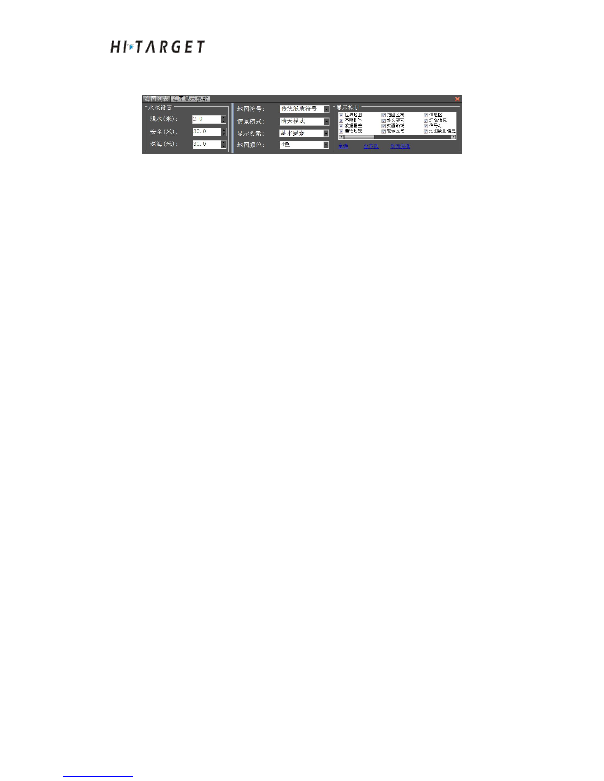
HD-MAX Echo Sounder User Guide
88
(2) Chart display parameters
Figure 11-6 Chart display parameters
Sounding setup: The sounding standard displayed by the chart. For example,
the area with a sounding less than 2m belongs to shoal waters, presenting in
dark color. The areas deeper than 30m belong to navigation safety area,
presenting in light color. And the areas with a sounding greater than 30m
belong to deep water area.
Cartographic symbols: There are two sets of graphic symbol libraries
displayed by electronic chart. The first type is traditional paper-based
electronic chart and the other type is simplified symbol figure.
Contextual model: While sailing on the sea, the electronic chart shall be
displayed in bright color at day time. During nights with dark light, however,
electronic charts shall be displayed in darker color in order not to affect
sailing at night. Five color patterns are generated respectively, namely:
sunny day pattern, day pattern, cloudy day pattern, evening pattern and night
pattern.
Display elements: Electronic charts include abundant information on icons,
symbols, text information, etc., and classify the information displayed. Some
of them are essential and are classified as basic elements. Some of them are
as standard information since they have to be displayed. Standard element
contains the basic elements. All-element display refers to show all
information.
Map color: Namely the display colors of sounding areas. Most parts of the
electronic chart are sounding areas. In order to distinguish different sounding,
the chart is to be displayed in four colors or two colors.
Page 89
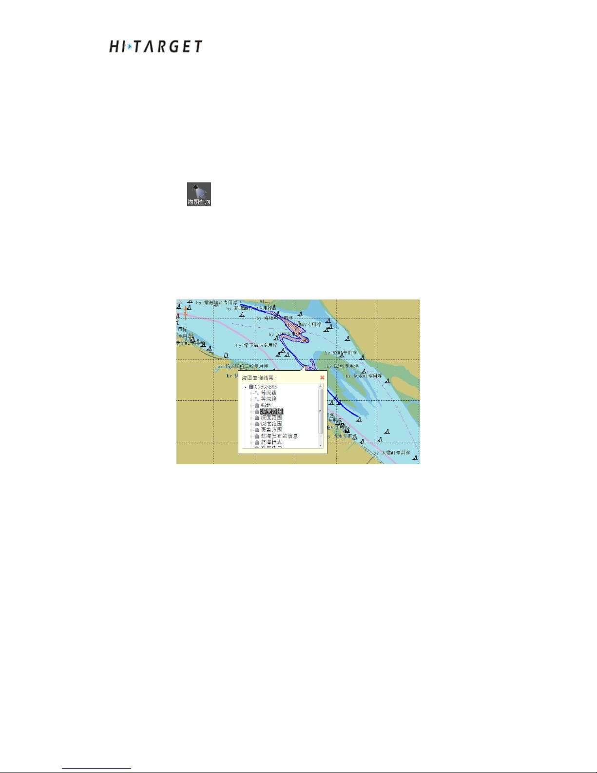
HD-MAX Echo Sounder User Guide
89
Display control: Electronic chart contains a lot of information. Those
information not requiring to be displayed can be hidden according to the
needs of the display.
Sea Chart Inquire
At [Planned route design] or [Marine surveying] interface, click [Sea chart
inquire] and then click the ground objects to be reviewed. Pop up the
bubble box of inquired results. List the ground objects of the position clicked
by the mouse in the bubble box. Select the ground objects in the bubble box.
And the ground objects at the view displayed by the electronic chart will be
highlighted.
Figure 11-7 Sea Chart Inquire
Conclusion of This Chapter
There are two methods to obtain electronic charts:①Chart data service
provider (such as bureau of maritime affairs)
②
The others If purchasing
electronic chart data from a chart data service provider, the user shall provide
equipment license code to ensure that the electronic chart can only be
displayed on the equipment with the license code. The equipment license
code of this system is only corresponding with Software Dongle.
Consequently, any device (such as computer) inserted with a Software
Dongle can display corresponding encrypted electronic chart. Electronic
charts are very helpful for marine surveying. Especially in unknown regions,
Page 90

HD-MAX Echo Sounder User Guide
90
electronic charts can be set as background reference to facilitate planned
route design and marine navigation. Furthermore, electronic charts also show
existing sounding points as reference base of sounding survey.
Page 91

HD-MAX Echo Sounder User Guide
91
Engineering Base Map
Introduction to this Chapter
■ Engineering Base Map Management
■ Engineering Base Map Display
■ Conclusion of This Chapter
CHAPTER
12
Page 92
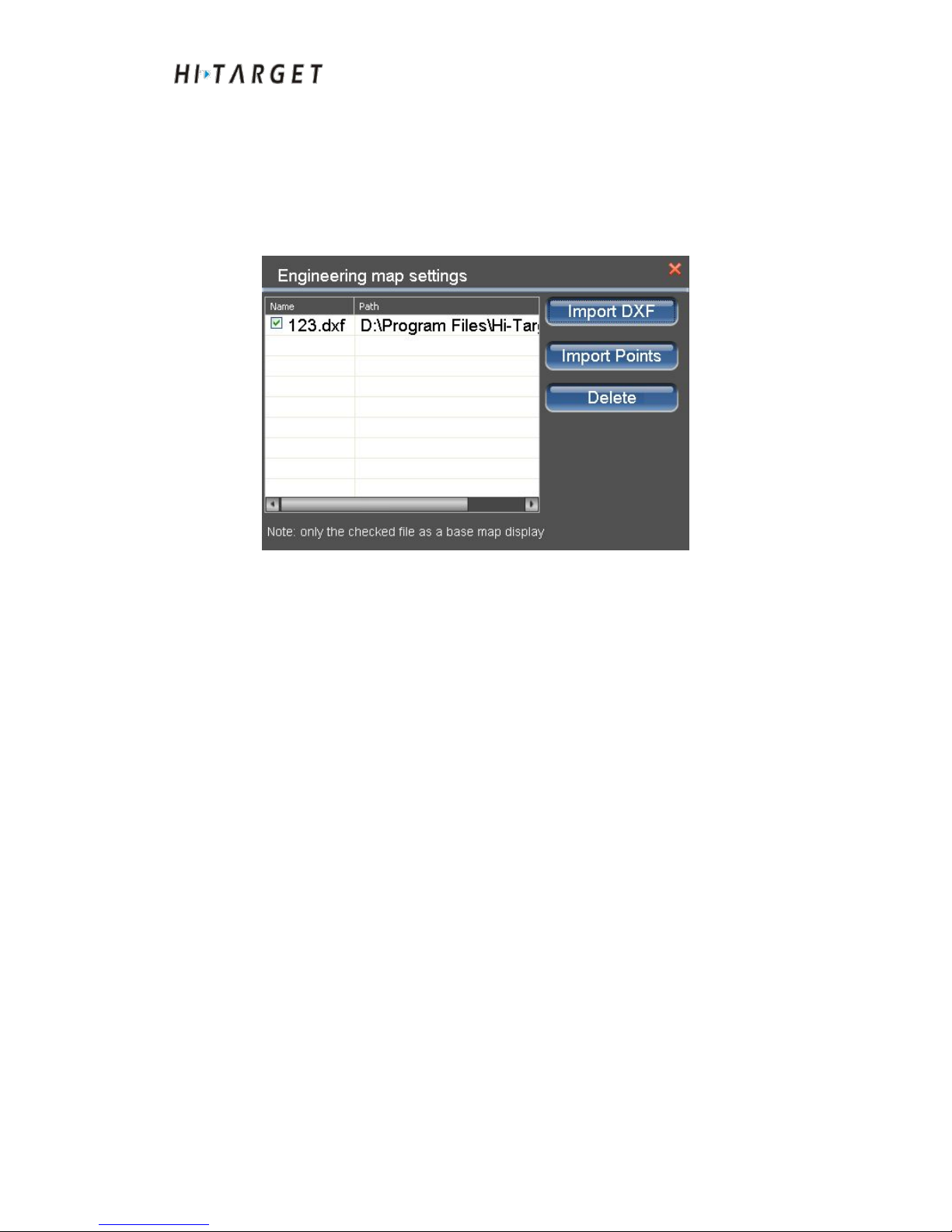
HD-MAX Echo Sounder User Guide
92
Engineering basemap Management
On the software main menu interface, click [BaseMap] to enter basemap
setup interface. The engineering basemap in DXF as well as soundings in
DAT formats can be imported and display can be controlled.
Figure 12-1 Engineering basemap
Import the engineering base map: Click [Import DXF] button and the
document dialog box will pop up. Select the file type and select the basemap
to be imported. Click [Open]. If the base map is opened successfully, the
document will be displayed in the documents list on the left.
Import the sounding point: Click to import the sounding point. CASS (.dat),
Hypack (.XYZ) or other files in user-defined formats can be imported. Select
the document formats to import the document. Select data and separators
according to user-defined format.
Page 93
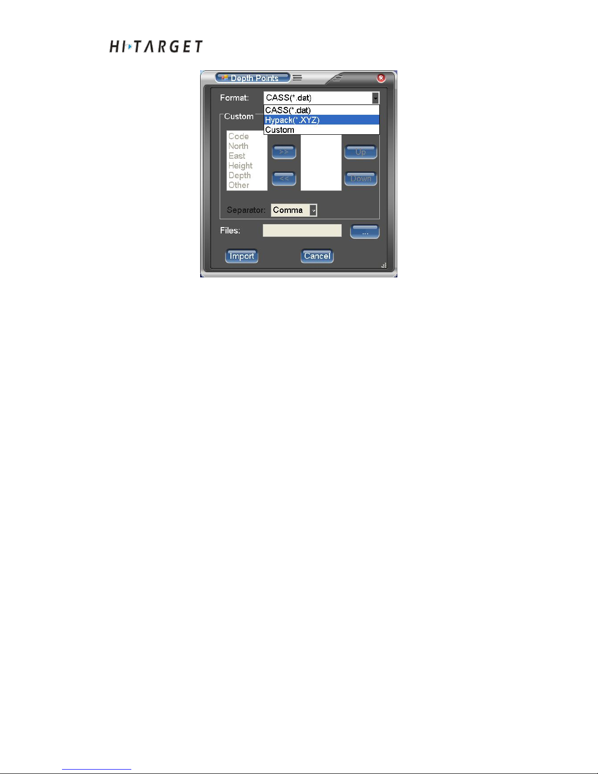
HD-MAX Echo Sounder User Guide
93
Figure 12-2 Soundings import
Delete engineering base map: In the file lists, select the items to be deleted
with the mouse and the items will be highlighted. Click [Delete].
Engineering Base map Display
At the engineering base map interface, click the engineering base map to be
displayed and exit the interface.
Page 94
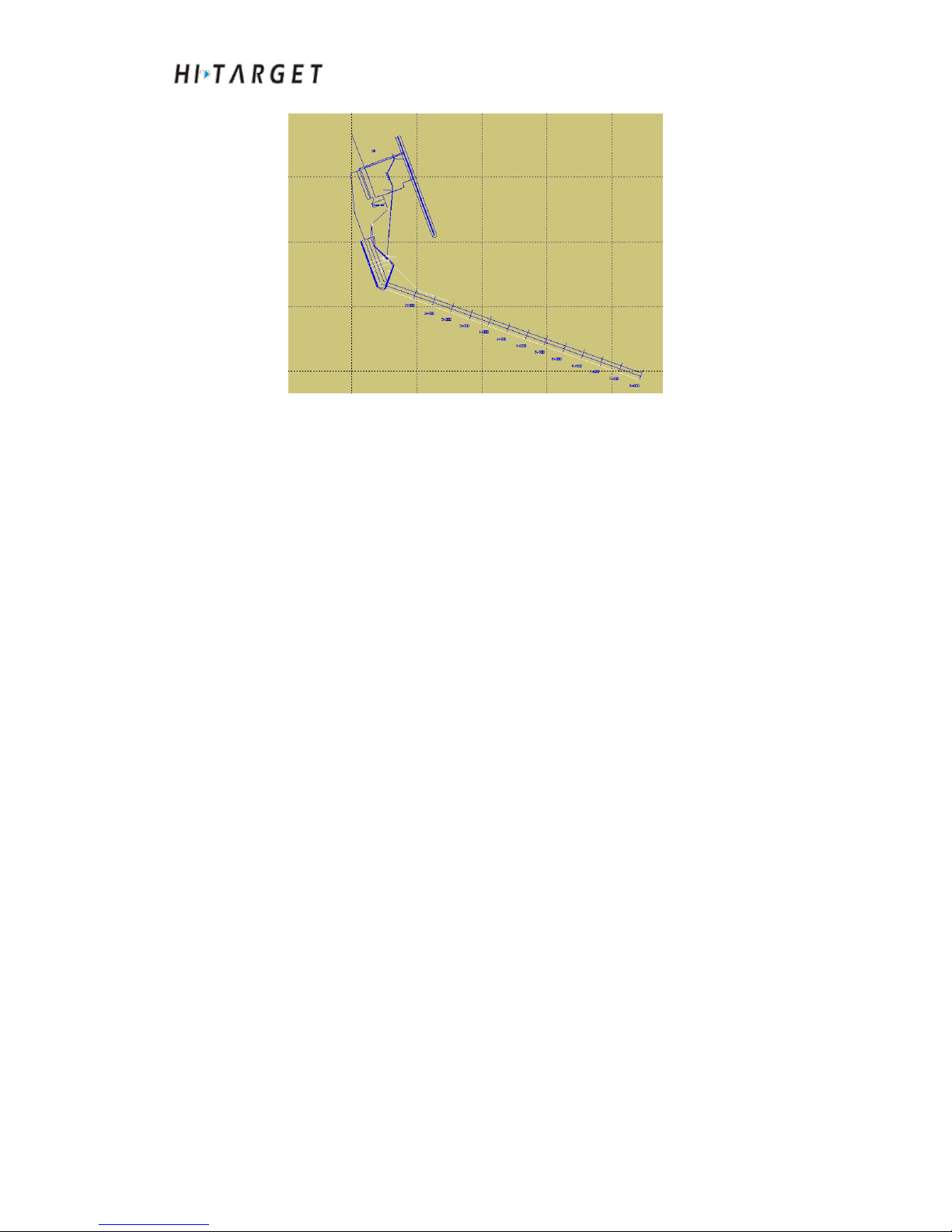
HD-MAX Echo Sounder User Guide
94
Figure 12-3 Engineering Base map Display
Conclusion of This Chapter
Engineering base map will show graphic elements of DXF such as circular
arc, straight line, line, broken line, polyline, text and fitted curve etc.. It can
display sounding points of DAT format as well. Engineering base map,
presenting as base map in marine surveying and planned route interface,
assists on planned route layout as well as marine surveying.
Page 95

HD-MAX Echo Sounder User Guide
95
C H A P T E R
13
Depth Measurement
Introduction to this Chapter
■ Common Functions Introduction
■ Parameters Setting
■ Data Acquisition
■ Conclusion of This Chapter
Page 96
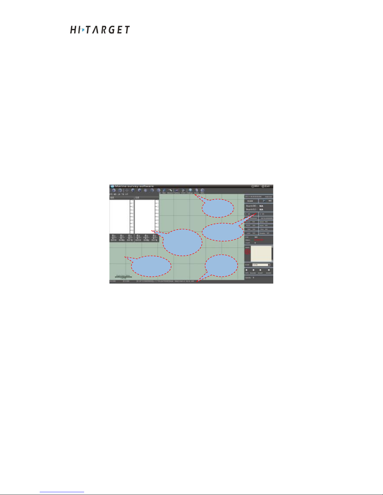
HD-MAX Echo Sounder User Guide
96
At the main interface of the software, click [Survey] to enter ocean depth
measuring interface as shown in Figure 13-1. Click the shortcut key of
instrument sounding, corresponding changes will show up at sounding,
playback, automatic, shift up, shift down interfaces;
Depth sounding: To control depth sounding of the instrument (start or
suspend sounding);
Playback: To look back sounding status of record data;
Shift up: To increase the sounding range;
Shift down: To decrease the sounding range;
Figure 13-1 Marine surveying interface
After entering the interface, the system will automatically enter the following
operation:
(1)
Automatically connect serial port and read serial port data.
(2)Automatically load the designed ship form data.
(3)Automatically load the planned route data layout.
(4)
Automatically load the electronic chart data and engineering base map.
Sounding
Toolbar
Informatio
n panel
Sounding
depth color
Prompt
column
Page 97
HD-MAX Echo Sounder User Guide
97
Common Functions Introduction
Graph zooming and Pan view
(1) Zoom
Zoom can be achieved by three ways:
①
Zoom in and zoom out tool
Click [ZoomIn] or depth sounding functional key , then the
view will be enlarged. If local amplification is required, you can drag a box
in the view or click left mouse button to zoom in with the position pointed by
the mouse as the center.
Click [ ZoomOut] or depth sounding functional key , then the
view will be zoomed out. If local shrinking is required, you can drag a box in
the view or click left mouse button to zoom out with the position pointed by
the mouse as the center.
②Overall graph zooming
Click [ZoomAll] . The view will display planned route, engineering
basemap, measurement data points, marking and other elements according to
the maximum range.
③Mouse pulley
When push the pulley forward in the view, the image will be zoomed in, and
when push the pulley backward, the image will be zoomed out with the
position pointed by the mouse as the center.
(2) Pan view
Pan view can be achieved by three ways:
①PanTool
Click [Pan] , press the left mouse button and drag the mouse to move
the image.
Page 98
HD-MAX Echo Sounder User Guide
98
②Middle mouse button
Press the middle mouse button and drag the mouse to move the image. The
shortcut operation will not affect the other operations, such as planned route
drawing. To move the bottom image, press the middle mouse button. After
the mouse changing to hand shape, drag the mouse to perform Pan View.
After loosening the middle mouse button, it can continue to draw planned
route.
③Shortcut key
By pressing the Up, Down, Left and Right key of the keyboard, the view
points will be moved to up, down, left and right. For example, when move
the view point to right side, the view background will move to the left side.
Ship position locking and heading
(1) Ship position locking
In the process of measurement, keep the ship position at the middle section of
the screen by real time moving view background which is equivalent to
locking the ship at the middle section of the screen. It is known as ship
position locking for short.
Ship position locking: Click [Unlock] to shift to ship position locking
mode. The icon will change to .
Ship position unlocking: Click [Locked] to shift to ship position
unlocking mode. The icon will change to .
Attention: Since under the ship position locking mode, the system will
automatically perform Pan View to keep the ship at middle
section of the ship. It is suggested to shift to unlocking mode
when carrying out view browse, planned route preparation,
mark drawing and other operations to shift to ship position
unlocking mode.
Page 99
HD-MAX Echo Sounder User Guide
99
(2) Ship heading
Ship heading function refers to rotate background base map to make the
direction of the bow pointing to upward direction of the screen. When
performing sounding survey according to the planned route, ship heading can
provide intuitive visual experience and is very helpful for ship navigation.
Heading up: Click [NorthUp] to shift to Heading up mode. The icon
will change to . If the ship position is locked, the view will automatically
rotate to keep ship bow direction pointing to upward direction of the screen.
North up: Click [ Heading up] to shift to North up mode. The icon will
change to . The view will automatically rotate to keep North up pointing
to upward direction of the screen.
Planned route drawing
Click [PlanLine] to enter planned route drawing mode. Specific
operations shall refer to Section I of Chapter VII "Planned route drawing"
Graphic symbol
During marine surveying process, some marks are required to be done, such
as marking the measured areas or marking water-based facilities at the
measurement area. The frequently-used graphic symbols include dot, line and
surface. The system supports point mark, line mark and surface mark. Click
[Mark], and a mark dialog box will show up at the bottom of the view. Marks
can be added with a mouse or coordinate. The marks can be edited, deleted
and exported as DXF files.
Page 100
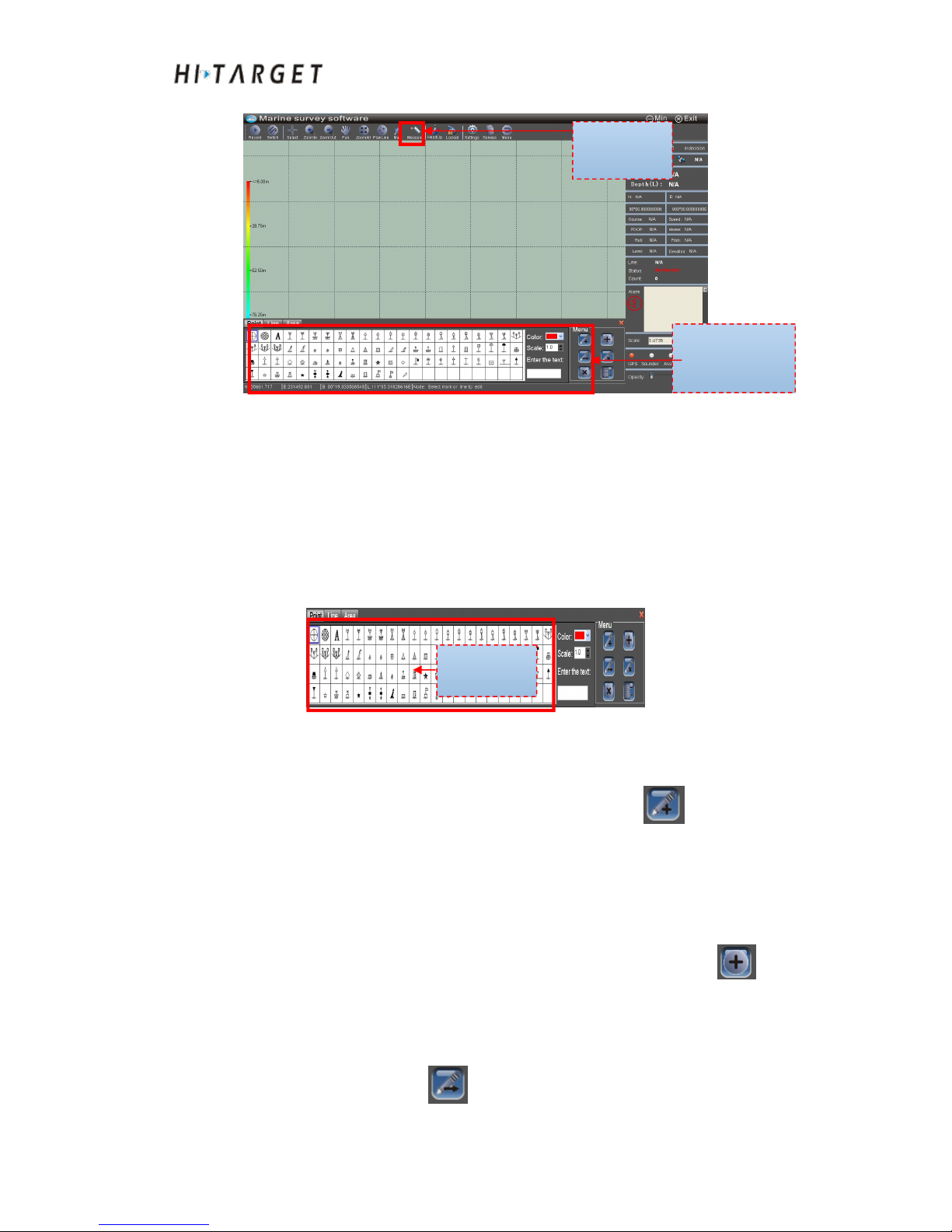
HD-MAX Echo Sounder User Guide
100
Figure 13-2 Marking
(1) Point mark
Attribute parameters of point mark include: Mark shape, color, and display
scale size. The generally required operations include: dot mark drawing with
a mouse, adding marks with coordinate, dot marks edit and dot marks
deletion.
Figure 13-3 Point mark
Dot mark drawing with a mouse: Select the shape, display, display size
proportion of the mark and click mouse drawing button . A dot mark
will be completed at the position pointed by the left mouse button in the
view.
Adding marks with coordinate: Select the shape, display, display size
proportion of the mark and click mouse coordinate adding button . A
dialog box of coordinate input will pop up. Input the correct coordinate in the
dialog box. Click [Confirm].
Dot marks edit: Click Edit . The mouse will select the dot mark to be
Marking button
Marking dialog box
Shape list
 Loading...