


V60 Getting Started
V60 Getting Started
Hi-Target
Surveying Instrument
All Rights Reserved
Co., Ltd

Content
V60 Getting Started
1. Introduction of hardware
1.1 Hardware structure
1.2 Buttons operation and screen display
1.3 Descriptions of indicator lamp on the control panel
1.4 Static collection and data transmission
2. Handheld controller and application
2.1 Introduction to the handheld controller
2.2 Appearance of the handheld controller
2.3 Handheld controller accessories
2.4 Operation of handheld controller
2.5 Installation of SIM card
2.6 Power on and power off operation
2.7 Data download
3. Hi-Survey
3.1 Creat a project
3.2 Measurement and collection
3.3 Export of data achievement
------------------------------------------------------------------------------------------------- 37
------------------------------------------------------------------------------ 1
---------------------------------------------------------------------------------- 2
----------------------------------------------------------- 8
------------------------------------------------------- 18
------------------------------------------------------------ 22
-------------------------------------------------------- 23
-------------------------------------------------------- 23
---------------------------------------------------------------- 26
---------------------------------------------------------------- 28
---------------------------------------------------------------------------- 31
------------------------------------------------------------- 33
-------------------------------------------------------------------------------------- 34
-------------------------------------------------------------------------------------- 38
--------------------------------------------------------------------- 74
---------------------------------------------------------------------- 84
--------------------------------------- 17
3.4 Stake out
4. Quick Guide of SurvCE
--------------------------------------------------------------------------------------------- 88
----------------------------------------------------------------------------- 108
I

V60 Getting Started
5. Technical parameters
5.1 GNSS specification
5.2 Precision of receiver
5.3 UHF transceiver
5.4 Interface
5.5 Physical characteristics
5.6 Environment requirements
6. Trouble shooting
6.1 Reset operation
6.2 Upgrade firmware
6.3 Correction data transmitting issues
6.4 Internet accessing issue
6.5 Transceiver issue
6.6 Signal descriptions of 5-core/8-core socket
6.7 Signal descriptions of V60 indicator lamp
-------------------------------------------------------------------------------------------- 130
------------------------------------------------------------------------------- 128
------------------------------------------------------------------------------- 129
----------------------------------------------------------------------------- 129
----------------------------------------------------------------------------------- 130
-------------------------------------------------------------------------- 130
--------------------------------------------------------------------- 130
------------------------------------------------------------------------------------- 131
----------------------------------------------------------------------------------- 132
-------------------------------------------------------------------------------- 132
------------------------------------------------------------------------ 136
--------------------------------------------------------------------------------- 137
---------------------------------------------------------- 133
------------------------------------------------ 137
--------------------------------------------------- 138
II

C
H
A
C
H
A
C
C H
H A
A P
1
Introduction of hardware
■ Hardware structure
■ Buttons operation and screen display
■ Descriptions of indicator lamp on the control panel
■ Static collection and data transmission
V60 Getting Started
P
T
E
T
T E
R
E
R
E R
R
P
P T
1

1. Introduction of hardware
1.1 Hardware structure
Hardware Schematic Diagram
Upper Cover
Bottom Cover
Control Panel
Fig.1.1-1
Introduction of hardware
Guard Circle
Control Panel
There are FN button, Power button and three indicator lamps on the control panel .Three indicator
lamps are satellite lamp (single green lamp), status lamp (bi-color lamp of red and green) and power
lamp (bi-color lamp of red and green) from the left to the right.
FN button (Function): Set work mode, data chain, UHF transceiver channel, satellite elevation angle,
sampling interval and restoration receiver, etc.
Power button (Function): for power on and power off, Set confirmation and inquiry of the current
work mode, etc.
2

V60 Getting Started
Upper Cover
Anti-wear Buffer
Fig.1.1-2
Anti-wear buffer: Anti-wear buffer can effective avoid the instrument from scratches.
Bottom Cover
9
8
7
6
5
4
Fig.1.1-3
1. 8-core socket and protective plug 2. 5-core socket and protective plug
3. Differential antenna port and protective plug: 4. Connecting screw hole
5. Battery cabin 6. Spring contacts power seat
7. SIM card slot 8. SD card slot
1
2
3
3

Introduction of hardware
3. Transceiver antenna port: Used to connect internal transceiver antenna for receiving and
transmitting differential signal.
Cautions:
1. when 8-core socket or 5-core socket is not in use, please cover them with the plug.
2. When water enters into the trumpet, it is likely that the trumpet is silent or hoarse.The voice can
recover after the trumpet is dry.
5-core socket and 8-core socket
Fig.1.1-4
1
8
1
2
3
5
4
2
3
4
Fig.1.1-5
7
6
5
4

V60 Getting Started
1. 5-core socket: It is also known as COM2/PW2, which is generally used to connect the receiver
with external data chain or the external power supply.
2. 8-core socket: It is also known as COM1/USB/PW1, which is used to connect with computer,
handheld controller and other equipment for downloading and deleting data.
Cautions: All the above are the front diagrams of sockets at the bottom of receiver when facing
to the receiver. (Namely the face of weld of plug)
Battery
Outside view of 5000 m Ah lithium battery
Positive pole
Negative pole
Fig.1.1-6
5

Introduction of hardware
Environmental requirements
V60 receiver is designed by waterproof material but please try to keep its environment dry. In order
to improve the stability and service life, please avoid the receiver from being exposed to extreme
environment for use, for example:
◇Humid environment
◇Temperature of higher than 65°C
◇Lower than -40°C
◇Corrosive liquid or gas
Electronic interference sources
Do not set the GNSS receiver at the place near electric power or strong interference signal, such as:
◇petroleum pipeline
◇Television and computer monitor
◇Generator
◇Electric motors
◇DC - AC power conversion equipment
◇Fluorescent lamp
◇Power switch
Basic Operations
Introduction of this chapter
Power supply system
Installation and dismantlement of battery cover
Unlock State Lock State
Fig.1.1-7
6

V60 Getting Started
Power supply mode
Table 3.1Power supply mode of V60 signal receiver
Power Supply Mode
Power Supply
Scope of Power Supply
V60 receiver can be supplied with the power by the external power supply of 8-core socket and
5-core socket at the bottom of receiver ,in which, once external power supply of 8-core socket is
powered on, the receiver can power on automatically. When the external power supply of 5-core
socket is powered on, the receiver can be powered on by pressing the power button on the control
panel of receiver.
External voltage range for GSM operation mode and UHF rover station is DC 6-28V and the current
shall be more than 1000mA. If there is external power supply, the receiver will choose the higher
voltage between the lithium and external power supplies. If it is needed to use the external power
supply, it is required to use the special power supply designated by Hi-Target.
Cautions:
1. Service time of lithium battery will decrease with the reduction of temperature and increase of
charging and discharging times. Generally, one new 5000 m Ah lithium battery can be used for
13-15 hours for static data collection, or 10-12 hours as GPRS Rover, or 8-10 hours as internal
transceiver transmitting station.
2. In case that electric quantity is used up, in order to avoid battery performance from damage, it
shall be used again after continuous charging for 24 hours.
3. If the battery is not used for a long time, in order to prolong its service time, please charge the
battery once per month.
Lithium battery, 8-core socket and
5-core socket external power supply
6V min. and 28V max.
7

Introduction of hardware
BL-5000 lithium battery must be charged by CL-8410 lithium battery charger dedicated by
Hi-Target. Charging time is about 7 hours.CL-4400 chargers is designed with charging lamps, which
becomes red during the charging period, and becomes green after charging. Then continue charging
for 1-1.5 hours until the electric quantity of battery is in full state.
Charging lamp
Charger lamp
Warnings:
1. only use battery and charger configured by manufacturer, and do not throw them into the fire or
use the metallic short-circuit electrode.
2. In case of heating, deformation, liquid leakage, smell emission or other anomaly phenomenon
during the use, charging or storage period of the battery, please stop using and replace it with new
one.
3. If the service time of the battery is shortened obviously, please stop using the battery. It indicates
that the battery has been aged; please replace it with new one.
Fig.1.1-8
1.2 Buttons operation and screen display
1. Control panel
For Hi-Target V60 receiver, most settings and operations can be realized by two keys on the control
panel.
8

V60 Getting Started
2. LCD Buttons operation
V60 GNSS RTK system can open/close the liquid crystal panel display by double clicking power
button. High-definition LCD panel with two buttons complete the basic work demands of receiver ,
which can set three work modes of base, rover station and static state flexibly. Detailed descriptions
of keys operation of control panel are as follows.
Double click button power to turn on the LCD, and the initial interface will display the current work
mode and relevant basic information.
Latency
Solution
status
Version
Work mode
Channel
Common-sate
llites
Fig.1.2-1
Power
supply
PDOP
Data chain
Received signal
strength indication
Work mode
Common-satellites
Static file name
Fig.1.2-2
9

Introduction of hardware
Operation
Single-click
Double-click
Long-time press
Super long-time press
Slow flash
Quick flash
Function
Turn on/Turn off LCD
display
Select the menu
Set confirmation
Display/Close
Initial interface
Switch over the data
chain
Description
Button operation time is less than 0.5 seconds
Interval time for double-click is more than 0.2s but less than 1s.
Button operation time is more than 3s.
Button operation time more than 6s.
The lamp is flash with frequency of more than 0.5s.
The lamp is flash with frequency of less than 0.3s.
Button operation
Double-click power button
Single-click Fn button
Single-click power button
Double click power button
Single-click Fn button
Single-click Fn button to
move choice box,
single-click power button to
confirm setting.
Function
Single-click the function button
then the choice box will jump into
the next option automatically.
Single-click power button; confirm
current content or move the choice
box to the next menu.
Display the work mode of receiver,
satellite information and version
information.
It displays as follows under the
RTK mode from left to right: data
chain, difference parameters, work
mode and system information
Data chain menu includes three
options: UHF (Internal
transceiver), External transceiver
and Return to previous menu.
10
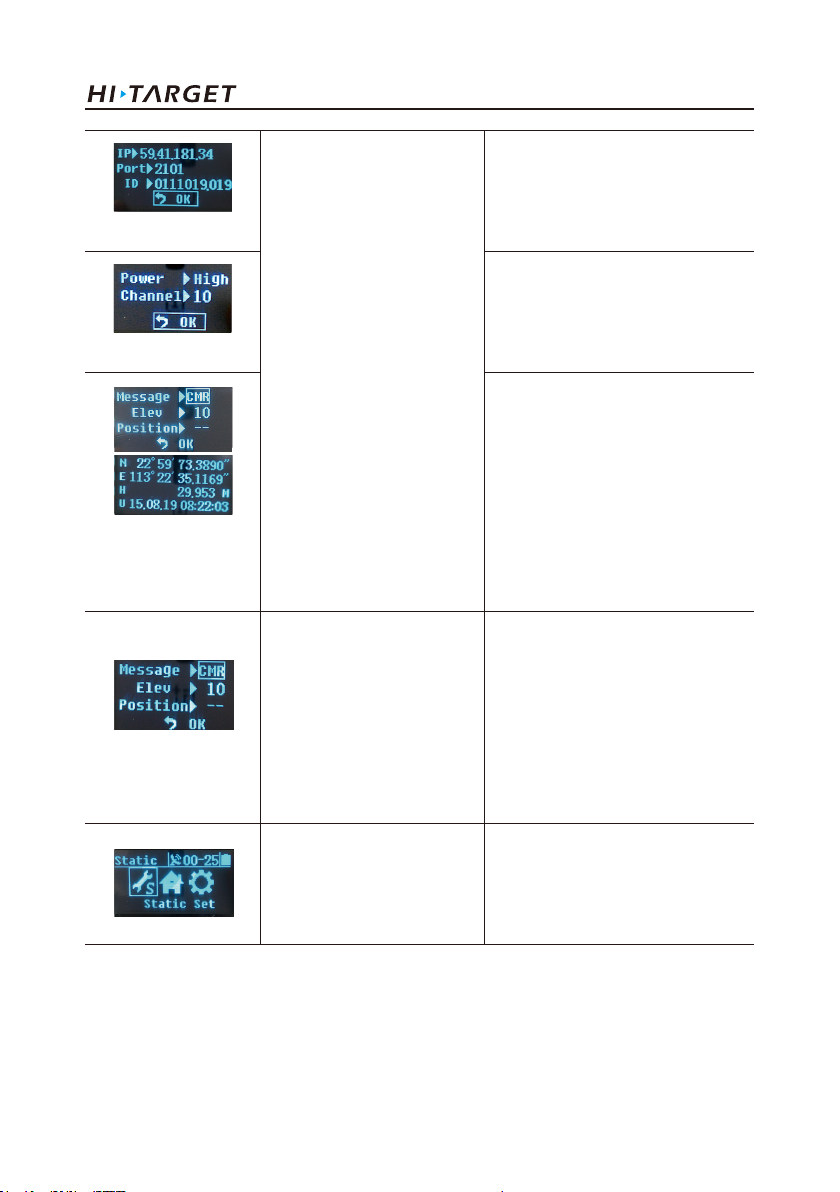
V60 Getting Started
Set GSM parameter
Set UHF parameter
Set parameter of
difference information
in the base
Set parameter of rover
station
Single-click button to select,
single-click power button to
edit, and select "OK" after
edition to confirm.
GSM data chain: input IP address
serial port; grouping No. , and
group No.
UHF (Internal transceiver): Select
among high, medium and low
power and channel between
0-115.
Set parameter of difference
information of the base:
1.Difference scheme:CMR/RTCM2
/RTCM3/sCMRx.
2.Cutoff angle of satellite: 0°-30°
3.Current position coordinates: B
L H
Set parameter of difference
information in the rover station:
Difference scheme: CMR/RTCM2
/RTCM3/sCMRx.
Cutoff angle of satellite: 0°-30°
GGA data transmission frequency
0s, 1s, 2s, 5s, 10s, 30s, 60s
It displays as follows under the
static mode from left to right:
Static setting Work mode and
System information.
11

Introduction of hardware
System information
Select '' '' single-click
the power button to return to
the previous menu.
In case of no Back on the
interface, single-click power
button to return to the
previous menu.
Static setting
Cutoff angle of satellite:0 °- 30 °
Sampling interval: 1s, 2s, 5s, 10s,
15s, 30s
System information provide with
current information of receiver,
stellar map and system status, etc.
System information
Editing parameters
Take edition of elevation angle for example, edit parameter of LCD interface following the sequence
from left to right and make a selection according to the popup digital choice box.
(1) Single-click Fn button to select the digit and single-click power button after confirmation, then
the cursor can jump to the next digit automatically.
(2) If it is not required to edit from the first digit, after opening the choice box, select or and
the cursor can jump to previous step or next step.
(3) After the completion of edition, single-click Fn button, and the selected box jumps into the next
edit item (such as sampling interval).Edit interface is changed as shown in the below figure:
→ →
12

V60 Getting Started
Attentions:
1. When the LCD interface is in the mode of parameter setting, and handheld controller cannot
connect with the receiver, it is required to wait for liquid-crystal operation to return to the main
menu.
2. For GSM data chain interface of parameter setting, it can take effect only by setting Hi-Target
server IP: 202.96.185.34; Port: 9000; Grouping number (7 bits); Group number (3 bits) on the panel.
Connect by CORS; the parameter setting must be conducted by the Hi-Target handheld controller
software.
3. The parameter setting (elevating angle, sampling interval) will be invalid during the static data
collection, and the successful parameter setting will take effect when the next static collection starts.
4. If button operation does not be made more than 50s under the liquid crystal display status, the LCD
can be turned off automatically and the system enters into pure button mode for saving power
consumption. The user can double click power button to restart the LCD.
3. Turn off the LCD only by button operation
If there is no LCD display status, work mode can be switched by two buttons and voice can be
provided to assist the user to complete the operation.
Function
Work mode
Data chain
UHF mode
Button operation
Double-click Fn button
(0.2s <Interval<1s)
Press Fn button for a
long time (>3s)
Single-click Fn button
Single-click Fn button
and long press Fn
button
Content
Enter into work mode of "base", "rover station"
and "static state" to select.
Enter into data chain mode of "GSM", "UHF" and
"External" and single-click Fn button to select
the mode.
Enter into "UHF transceiver channel" setting.
There are 116 channels from 0 to 115 for
selection. And when the numbers of channel are
more than 15, it is recommended to use liquid
crystal and software setting, which make more
quick and convenient.
Increase the channels ten by ten.
13

Introduction of hardware
Set
confirmation
Automatically
set the base
Receiver
restoration
Single-click
power button
Key Fn power button
for power on
Super long-time press
Fn button
Voice prompts the current work mode, data
chain mode and radio power and channel;
meanwhile, the power lamp indicates the battery
capacity.
Firstly press Fn button, then press power button
for power on and do not loosen Fn button until
"Ding-dong" sound is heard. Voice prompts
confirmation and current status of receiver.
Reset mainboard. After resetting the receiver, if
the handheld controller bluetooth cannot be
connected with the receiver, firstly adjust the
receiver to be in the static mode and adjust it
back after starting the collection.
4. Power on and power off the receiver
Table Display State Descriptions of Indicator Lamp under the Mode of Power on and
Power off
Power on
Power off
Press power
button for 1s
Press power
button for 3s
All indictor
lamps are on.
All indictor
lamps are off.
Power on music, voice prompt of work mode
and data chain mode before the last power off
Power off voice
The display state of indicator lamp is different under different setting mode. Please refer to Chapter
6.7: Descriptions of control panel indicator lights
SIM /USIM card
Receiver adopts network data chain mode to implement RTK operation. It is necessary to prepare
network communication card and open corresponding data communication services. The required
number of card is determined according to your RTK measurement system configuration. Each
receiver and handheld controller can be equipped with one card. The receiver supports SIM card and
USIM card.
14

V60 Getting Started
USIM card
SIM card
Table Descriptions of SIM card/USIM card
GPRS(ZHD/VRS)
GSM
GPRS(ZHD/VRS)
GSM
Installation procedure of SIM card:
(1) Demount the battery cover and remove the battery to make the SIM card slot exposed.
SD slot
Fig.1.2-3
(2) Put SIM card in the card base and insert it into the slot with the front (the side with metal contact)
facing downward without loosening.
SIM slot
Fig.1.2-4
15

Introduction of hardware
5.Transceiver
UHF transceiver
Internal transmitter-receiver (Standard configuration)
Band of transceiver: 450-470MHz, 116 channels can be switched over flexibly.
Transmitted power can be adjusted among 1W, 2W and 5W.
Transmission rate: 19.2Kbps and 9.6Kbps, which are available for adjustment.
PCC XDL transceiver module (Optional purchasing)
Transceiver frequency: 403MHz-473MHz, frequency table can be modified by yourself.
Transmitted power can be adjusted among 0.1W, 1W and 2W.
Transmission rate: 19.2Kbps and 9.6Kbps, which are available for adjustment.
Support a variety of transmission protocols.
Cautions: Once transceiver channel of the base is modified, rover also need to be modified to
the corresponding channel, otherwise, the differential signal cannot be received. Normal operations
made only under the same channels.
6. Power on to switch to UHF rover mode
(1) Double-click power button to power on LCD and the initial interface will display the current
work mode and relevant basic information. See Fig.1.2-2.
(2) Set work mode: Single-click Fn button, it shows as follows from left to right under the RTK
mode: Data chain, difference parameter, work mode and system information.
Operation steps are shown as follows:
→ →
Single-click power button for confirmation when the steps are finished.
16

V60 Getting Started
(3) Set data chain:
→ →
Single-click power button for confirmation when the steps are finished.
1.3 Descriptions of indicator lamp on the control panel
Display state of indicator lamp under different setting mode:
1. Work mode (Double-click Fn button to enter into the work setting mode, then single-click Fn
button to make mode selection and click power button for confirmation. In case of failing to press
power button exceeding 10s, confirmation can be done automatically):● On;○ Off
Table 2.1 Descriptions of display state of indicator lamp under the work mode
Mode
Base
Rover
Static state
Satellite lamp
(single green lamp)
●
○
●
Signal lamp
(the green lamp of the double lamps)
○
●
●
2. Data chain (Long-time press Fn button to enter into the data chain setting mode and then
single-click Fn button to make mode selection and click power button for confirmation. In case of
failing to press power button exceeding 10s, confirmation can be done automatically):● On;○ Off
Table 2.2 Descriptions of display state of indicator lamp under the data chain mode
Type
UHF
Internal GSM
External
Satellite lamp
(single green lamp)
●
○
●
Signal lamp
(the green lamp of the double lamps)
○
●
●
17

Introduction of hardware
1.4 Static collection and data transmission
Introduction of this chapter:
■ Introduction
■ Static measurement of the receiver
■ U disk-type data download
■ Operation of static management software
Introduction
The collecting static measurement data is stored in the receiver or the memory card. Static data file
needs to be downloaded into the computer and processed by the static post-processing software.
Static measurement of the receiver
1. Set up instrument at the control point and strictly keep the optical plummet centering and leveling.
2. Measure the height of instrument three times and difference among them shall not be more than
3mm, and the average value of them is the final height of instrument. Height of instrument is the
distance from mark-stone center of control point to measurement marker line of receiver.
3. Parameter of the receiver:
◇ Receiver radius:91mm
◇ Height between the bottom of receiver and antenna phase center :94.2mm
◇ Height between measurement line of receiver height and antenna phase center:39.3mm
*If the antenna parameter certificated by NGS is needed, please view
http: //www.ngs.noaa.gov/ANTCAL/Antennas.jsp?manu=HI-Target
5-core socket and 8-core socket
18
Phase center
39.3
94.2
91
Fig.1.4-1

V60 Getting Started
4. Record point name, instrument No. height of instrument, time of beginning observation.
5. Power on, set the receiver to be static measurement mode according to the following button
operations:
(1) Set work mode:
Single-click Fn button, it shows as follows from left to right under the RTK mode: data chain,
difference parameter, work mode and system information.
→ →
Single-click power button to confirm the selection.
(2) Set static collection parameter:
→
Adjust cutoff angle of satellite and sampling interval. Move the choice box again, and single-click
power button for confirmation.
Flashing satellite lamp indicates searching for satellite,and it indicates that the satellite has been
locked if satellite lamp turns on. State lamp flashes according to sampling interval and each flashing
indicates that one epoch is collected.
6. Power off after the completion of measurement and record the power off time.
7. Download and process data.
Cautions: Do not move base .Do not change collection parameter during the collection.
Data download by USB flash disk:
Receiver files are managed and stored by USB flash disk and it is not necessary to download drive
program. Only download the static data of receiver but not conduct read-write operation for the
receiver. The receiver can conduct U disk-type data download by using Y-type data line, of which
one terminal is connected to the computer USB and the other terminal is connected to the 8-core
socket on the bottom of receiver. After the connection, drive of "static" and SD card can appear in
the computer. Copy the collected static file after opening the drive.
19

Introduction of hardware
Fig.1.4-2
The procedure of modifying the point name and antenna height of the downloaded static file as
follows:
1. Select *GNS static file and double-click the mouse.
2. After popup of dialog box of "File Editor", modify the point name and inputting antenna height
and click [OK].
Fig.1.4-3
Cautions: Static files in the removable disk cannot be deleted directly but can be deleted by
management software of GNSS receiver or handheld controller software.
Operation of static management software
Main functions of management software of GNSS receiver:
◇ Delete original data and files.
◇ Delete and format the whole memory.
◇ Read and set parameter.
◇ Set storage path of static data.
Operation procedures:
1. Separately connect 8-core socket and serial port of the computer by using two terminals of Y-type
data line.
2. Select the computer port and click it to connect the serial port.
3. Refresh the catalogue and then observed data files can display in the form.
4. File Name: There are eight bit characters.
5. Create Time: Time of file creation.
20

V60 Getting Started
6. Data deleting. Select the data required to be deleted and click Delete to delete the selected files.
7. Set collection interval and cutoff angle of satellite: Input the value to be changed and click to set
the parameter. Click read parameter and will show the originally set collection interval and cutoff
angle of satellite.
8. Format data:Click "Format/Del All Files" to complete the formatting of receiver and all data are
deleted, which cannot be recovered.
Fig.1.4-4
21

Handheld controller and application
C
H
A
H
A
H A
A P
P
P
P T
C
C
C H
2
Handheld controller and application
■ Introduction to the handheld controller
■ Appearance of the handheld controller
■ Handheld controller accessories
■ Operation of handheld controller
■ Installation of SIM card
■ Power on and power off operation
■ Data download
T
T
T E
E
R
E
R
E R
R
22

V60 Getting Started
Introduction to the handheld controller
◇ Industrial design, IP68 design, resistance to fall from the height of 1.2 m and adaption of all kinds
of complicated working environments outdoor
◇ 640*480 Highlighting LCD with 3.7 inches can be readable normally under strong sunlight
◇ Support bluetooth, Wi-Fi, Network and provide convenience for achieving a variety of wireless
data transmission with receiver.
◇ Internal camera with 8 million pixel, which supports field collection of high-definition image
information
◇ Internal 6300 m Ah lithium battery, which supports continuous work for above 20 hours
◇ 1.5GHZ of basic frequency, quad-core CPU;4GB Internal Memory +1GB RAM memory; Internal
Micro SD card slot, which supports 32GB expansion card at maximum
◇ Dual SIM dual stand by, which support WCDMA and GSM system: Android 4.2
Attentions
Although iHand20 handheld controller adopts anti-chemical agent and impact-resistance material,
precise instrument shall also be used and maintained carefully and be in dry environment as far as
possible. In order to improve stability and service period of iHand20 handheld controller, please
avoid it from being exposed to extreme environment for use, for example, humid, high temperature,
low temperature, corrosive liquid, gas, etc...
Warnings:iHand20 handheld controller shall be used and stored within the specified
temperature of -20℃-55℃.
Appearance of the handheld controller
Front of handheld controller
The front of iHand20 handheld controller includes touch screen, keyboard and microphone.
23

Fig.2- 1
Handheld controller and application
Touch screen
Keyboard
MIC
Touch screen: Multipoint capacitive touch screen with touch pen, which supports Chinese and
English input.
Keyboard: Photograph, direction control, switch between Chinese and English, data collection,
volume control, power on, power off and other functions.
Microphone: Internal microphone can be used for field collection of voice message.
Reverse side of handheld controller
Handheld controller:There are camera, battery cover, belt, trumpet, etc. on the reverse side of
iHand20 handheld controller.
24

Fig.2- 2
V60 Getting Started
TrumpetCamera
Battery cover
Belt t
Camera: Used for field collection of image information.
Battery cover: Internal removable lithium battery.
Belt: Connect the belt to prevent sliding down.
Trumpet: Conduct real-time voice broadcast for the instrument operation and status.
25

Handheld controller and application
Side of handheld controller
Waterproof & dustproof rubber cover
Mini USB: Used for connecting USB data line and iHand20 handheld controller.
Audio port: Used for connecting headphone cable and iHand20 handheld controller.
Warnings: In case of not using audio port or Mini USB, please close the rubber cover so as to
achieving waterproof and dustproof.
Audio port
Mini USB
Fig.2- 3
Handheld controller accessories
Charger
Charger: 5V/1A
Fig.2- 4
26

V60 Getting Started
Battery
Lithium battery: 3.7V /6300mAh
Data line
USB data line:
◇ Connect to the USB port of computer, and used for download of data
◇ Connect to the USB port of charger and used for charging handheld controller
Fig.2- 5
Fig.2- 6
Touch pen
Fig.2- 7
Touch pen: In case of using touch pen to operate the handheld controller, it is required to start the
function of "handwriting pen", and open the handheld controller’s [system setting] → [auxiliary
function] → check [handwriting pen]
27
Handheld controller and application
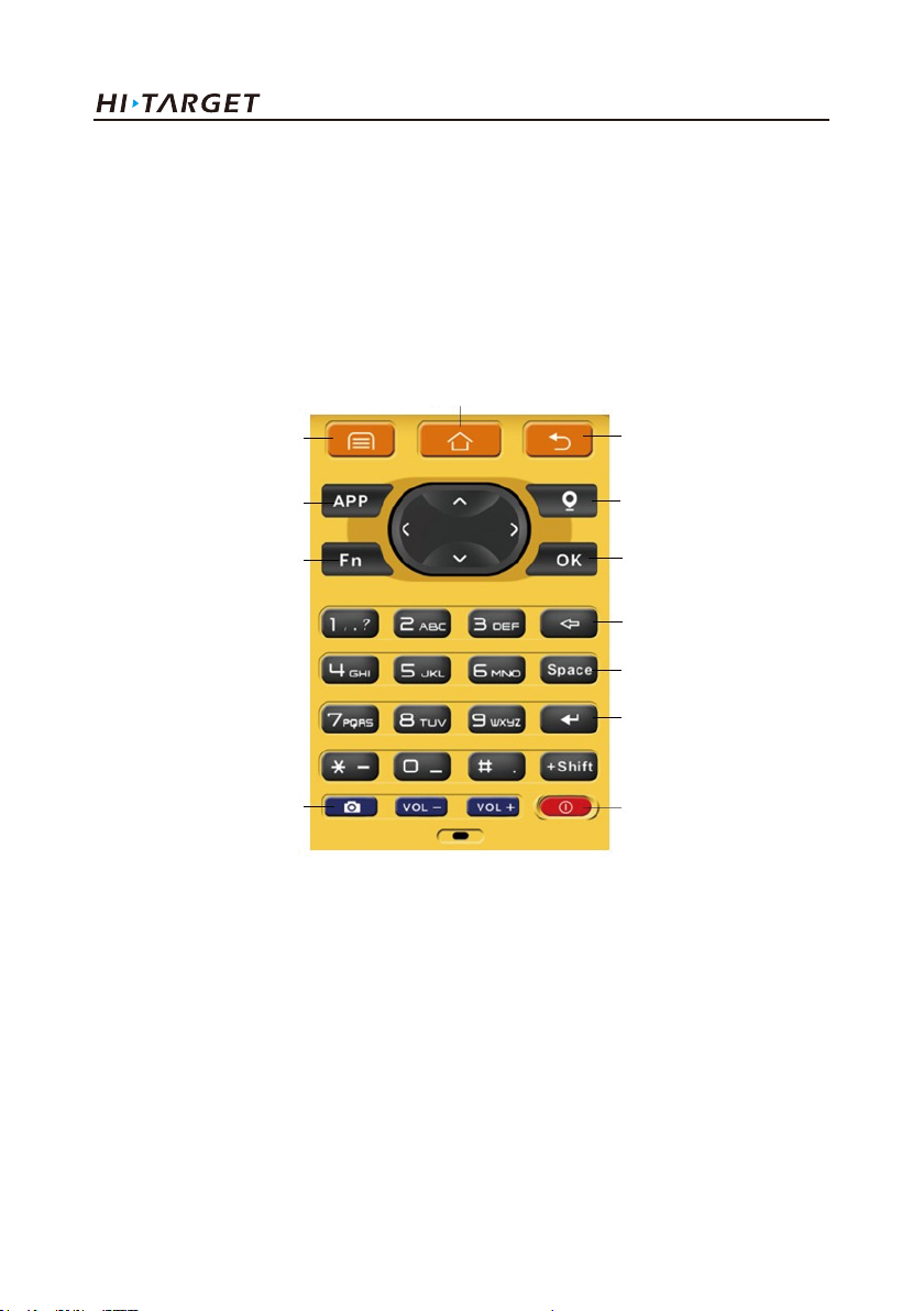
Operation of handheld controller
Keyboard
Most settings and operations of Hi-Target iHand20 handheld controller can be completed by the
touch pen, and commonly used operations can be completed by keyboard. Appearance and functions
of keyboard are introduced briefly as follows.
Home
Menu
APP
Fn
Fig.2- 8
Handheld controller 20 keyboard include: Back, OK, Power, APP, Fn, Collect, Camera, etc. on
buttonboard of iHand 20 handheld controller.
Button Back: Delete or exit the operation of current window.
Button OK: Confirmation
Button Power: Press it for above 3s for power on/ power off. Under the power on status, press power
button for 1s to turn off / turn on the screen backlight.
Back
Collect
OK
Del
Space
Enter
PowerCamera
28

V60 Getting Started
Button APP: Quick start of Hi-Survey software, press button APP for a long time for the Road
popup, then select "Hi-Survey Road" and click [Ok]. And the software selected this time can be
started quickly only by pressing key APP next time.
Cautions: When installing Hi-Survey Road for the first time, it is necessary to press key APP
for 3s for software quick start selection settings. Otherwise, corresponding software cannot be
started quickly by only pressing button APP.
Fig.2- 9
Fn button: Press Fn button for 3s and popup interface of input method switch so as to achieve fast
switch of input method. In case of [physical button input method], only press Fn button to switch
over input methods of Chinese Pinyin, strokes, digitals and letters under input status.
29

Handheld controller and application
Fig.2- 10
Collect button: Collect data by manual operation.
Camera button: Press it for a short time to enter into photograph interface; Press it for 3s on the
non-camera interface to start up/shut down flashlight function.
Screenshot function: Press "VOL-" and power button simultaneously for 3s, screen capture will be
kept in the file of "Mobile phone storage→ Pictures→ Screenshots".
Cautions:
1. When the iHand20 handheld controller is not used in the work, please turn off the backlight for
saving electric quantity and prolonging the working time.
2. Only the image collection interface supports the shortcuts operation. In order to avoid the input
conflict of input box, the text interface does not support shortcuts operation.
(1) Average collection shortcut is Key "7";
(2) Indirect measurement shortcut is Key "8".
Table 6.1 Model of iHand20 handheld controller battery and charger
Name
Lithium battery
Charger
Model
BL-6300A
CL-6300A
30

V60 Getting Started
Charging:
It shall be charged with special charger within a certain
temperature range and a certain charging time. Specific
usage methods and requirements: It shall be charged by
special charger with standard configuration of iHand20
within the temperature range of 0℃-40℃.For the first usage,
there is a certain electric quantity in the battery generally.
Therefore, the battery shall not be charged until the electric
quantity is used up. And it shall be charged for 12 hours for
the first three times and later it can be charged normally.
Warnings:
1.Must use battery and charger configured by manufacturer,
and do not throw them into the fire or use the metallic
short-circuit electrode.
2. Each charging time shall not be more than 24 hours.
3. In case of heat, deformation, liquid leakage, smell
emission or other anomaly during the use, charging or
storage period of the battery, please stop using the battery
and replace it with new one.
4. If the service life of the battery is shortened obviously,
please stop using the battery. It indicates that the battery
has been aged; please replace it with new one.
Installation of SIM card
Handheld controller supports dual SIM dual stand by and is provided with two SIM card slots, of
which SIM1 is defaulted to support GSM, WCDMA and SIM2 supports GSM.
Cautions: iHand20 does not support 4G network temporarily. If using 4G card on the handheld
controller, it is required to open 2G service.
31

Handheld controller and application
Installation procedures of SIM card
1. Unload the battery cover and remove the battery to make the SIM card slot expose.
SIM1 SIM2
2. Put SIM card in the card base and insert it into the slot without loosening with the front (the side
with metal contact) facing downward.
Installation Procedures of Micro SD card
1. Unload the battery cover and remove the battery to make the Micro SD card slot expose.
2. Push downward with the tip of the finger by resisting the sheet metal of slot to open the sheet
metal.
Fig.2- 11
Fig.2- 12
Fig.2- 13
3. Insert the Micro SD card into the card seat and the side with metal contract is placed down.
32

V60 Getting Started
Fig.2- 14
4. Push upward with the tip of the finger resisting the sheet metal of slot until it is stuck without
looseness.
Power on and power off operation
Under the power off status, press the power button for 3s to power on;
Interface
Under the power on status, press the power button for 3s, and then popup the prompt box and click
"Power off".
33

Handheld controller and application
Fig.2- 15
Data download
Connect handheld controller to computer
1. Connect handheld controller to computer by supporting USB data line, and pull down the notice
column and click USB computer connection [open USB storage].
Fig.2- 16
34

V60 Getting Started
2. If it is required to synchronously operate handheld controller or install and use third-party
software to debug data on the computer, "USB debugging" function shall be ticked. Turn on the
handheld controller, and click [System Settings]→[Developer options ]→[USB debugging] on the
desktop menu.
Click[System Settings]
[Developer options]
35

Handheld controller and application
[USB debugging]
3. In the popup debugging window, click [OK] to complete the connection between handheld
controller and computer.
4 In the computer, file operations between handheld controller and computer can be conducted by
[Portable Devices].
Fig.2- 17
36

Hi-Survey
■ Creat a project
■ Measurement and collection
■ Export of data achievement
■ Stake out
V60 Getting Started
C
H
A
P
T
E
C
H
C
C H
H A
A
A P
P
P T
T
T E
R
E
R
E R
R
3
37

Hi-Survey
3. Hi-Survey
3.1 Setting
1. New project
After new project is built before the measurement, the collected data will be saved in the project.
When building new project, relevant setting needs to be conducted, for example, setting of project
information, and coordinate system, etc..
Specific procedures as follows:
(1) Open the software Hi-Survey;
Single-click "Hi-Survey" to open it
(2) Click "Project Info";( As shown in Fig. 3-2)
38
Fig.3-1

Fig.3-2
(3) Input project name in "Name" box->click "OK";
V60 Getting Started
"Project Info": New project can be
built and the existing project can be
opened or deleted.
Input project name in "Name"
box->click "OK";
(Note: The name of new project shall
not be the same as the name of old
projects)
39

Hi-Survey
2. Bluetooth connection
Receiver is connected with handheld controller by bluetooth, therefore, it is necessary to do
this step before the operation. If conducting RTK under the mode of UHF (transceiver), two
sets of receiver bluetooth shall be configured at least (one for base and one for rover).
(1) Device ->Blue Tooth->Connect->Search device;
Click "Device" to connect receiver to
handheld controller
Select the connection type
"Bluetooth"
40

Click "Connect"
Click "Search device" to search the
bluetooth device nearby.
V60 Getting Started
41

Hi-Survey
(2) Select S/N code of the device to be connected->input bluetooth PIN"1234";
Configuration PIN of buletooth:1234
Click "OK" to connect
(May take a few seconds)
42

After connection, the interface will
display current work mode, firmware
version, firmware version of GPS
main -board and log-on message,
etc...
(3) Use the same method to connect with other GPS receiver (Such as 10211158).
Connection Process
V60 Getting Started
43

Hi-Survey
Connected
3. Set coordinate system
For measurement, coordinate system must be configured, because it is related to the accuracy
of coordinate.There are two methods to set the coordinate system. A. build a new coordinate system,
including Ellipsoid projection and Ellipsoid transformation parameters, etc. B&C. Import existing
coordinate system.
44

Click Project Settings:Including
settings of project and coordinate
system information
Enter settings interface
V60 Getting Started
45

Hi-Survey
A .Build a coordinate system:
Projection->Ellipsoid switchover->Elevation fitting
(1) Click "Projection"-> ->User Defined
Click to enter into the setting
interface.
User Defined:User can conduct the
setting according to his own local
parameter.
46

V60 Getting Started
(2) Input projection information (Input ellipsoid information according to local actual situation)
Click "System" to input name of coordinate system->"Projection" to select projection mode and take
"Transverse Mercator" for example.
System: Define the name of coordinate system
Projection: Optional
(take Transverse Mercator for example)
C. Meridian: Center meridian
(According to the local situation)
False Northing: Unit: meter
(According to the local situation)
False Easting: Unit: meter
(According to the local situation)
Lat. of False Origin: Latitude of False Origin
(According to the local situation)
False Easting: Additive constant in the
direction of east;
Scale Factor:(Adjustable in accordance with
actual situation)
Fill other information or not.
47

Hi-Survey
(3) Click "Datum", set Source Ellipsoid and Local Ellipsoid,
Click "Datum", set Source Ellipsoid
and Local Ellipsoid, but the ellipsoid
information is determined by local
and project requirement and must be
accurate.
Source Ellipsoid: Optional,
commonly use WGS84
48

V60 Getting Started
Local Ellipsoid: (optional)
determined according to specific
requirements;
Note: The parameters are different
according to different ellipsoid.
(4) Select switchover model: click "Model"; take Bursa-Wolf (Boolean Sally seven parameters) for
example.
Click "Model" to select switchover
mode
49

Take Bursa-Wolf for example
Input switchover parameters
DX: X Translation
DY: Y Translation
DZ : Z Translation
RX: X Rotation
RY: Y Rotation
RZ: Z Rotation
K (ppm): Scale factor.
All the above information shall be
confirmed locally.
Hi-Survey
(5) Height fitting (It can be skipped over if the fitting is not required)
Height->select elevation fitting mode; (complete elevation fitting)
50

Click Height->Model
Including modes of Geometric
Surface, TGO, Grid and Free Survey.
V60 Getting Started
51

Hi-Survey
File:Add file->Click "save"
(6) Click "Save" to complete settings and saving of coordinate system.
B. Add existing coordinate system files(user-defined)
1) Click "dam" ->Select .dam File; Click to return the parent directory. Path: SD Card
->ZHD->Geo Path ->select .dam file (take the addition of DD. dam for example) ->click "OK".
Click "dam" to add created dam
system file.
52

Select dam File; click
Path is: SD Card ->ZHD->Geo Path
Note: Till seeing the SD card
catalogue,
Click" " to return to the parent
directory.
V60 Getting Started
53

Select coordinate system files, with
the suffix of .dam. And click "OK" to
complete the selection.
(2) Return " "- > select .dam file->click "Apply"-> select "OK";
Return " "-> select .dam file
Hi-Survey
54

V60 Getting Started
Click "Apply"-> select "OK";
C. Add coordinate system files(Hi-Survey software BYO)
The software adds many coordinate systems all over the world intelligently for reference and
selection.
(1) Return" "->"Predefined"
Return" "
55

Click "Predefined"
(2) Select the continent located, take Eastern Asia for example;
Select continents and countries in the
region where you are located. For
example, select the Eastern Asia.
Hi-Survey
56

V60 Getting Started
(3)Add corresponding coordinate system file into "Predefined List" ->select the file->click "Apply"
to apply it to current project.
Select corresponding coordinated
system and add it into the list.
Select corresponding coordinated
system and add it into the list.
57

Hi-Survey
Click "OK" to complete the
application
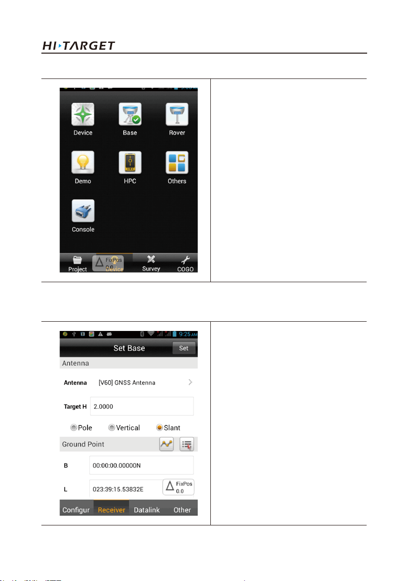
4. Set the base
Set the base,setting parameter of base after bluetooth connection. Including: coordinate of base,
communication mode, difference scheme, etc... Base is responsible for transmitting difference to the
rover so as to conduct real-time difference. The base can be set by handheld controller only when the
device bluetooth has been connected.
(1) Open software "Main interface" ->Device->confirm current connected GPS receiver
58

Open software "Main interface"
->Device
Confirm current connected GPS
receiver (take 11001649 for example)
V60 Getting Started
59
Hi-Survey
(2) For example: Set 11001649 as Base;
(3) Select "type of antenna" ->input "target height"(Target H)
PS: Select type of antenna according to the type of receiver, V60forexample.
For example: Set 11001649 as Base;
Antenna: The system can be default
to select corresponding type of
antenna (but is can be selected
autonomously);
Target H:Target height need to be
measured actually. Slant height is
normally used for the base and pole
height is commonly used for the
rover.
60

V60 Getting Started
(4) There are three methods to set "coordinate of base":
A. Input with known point. B. Get by average. C. Select from the collection point library;
A. Input with known point.
1) Ensure accuracy of coordinate of base;
2) Select "geodetic coordinates BLH" or "local coordinates NEZ". (Take BLH for example)
Select "geodetic coordinates BLH" or
"local coordinates NEZ". (Take BLH
for example)
B. Get by average
1) Click" "->Click "OK" to obtain position of base.
61

Click" "
Click "OK" to obtain position of
base.
Hi-Survey
62

V60 Getting Started
C. Obtain from point library
1) Click " "
Click" "
In the point library, there are
"original data" and "control point"
data, etc. for optional.
63

Hi-Survey
(5) Set data chain, including
A. "Internal UHF", B."Internal GSM" (Omitted), C."External Device"
Click "Datalink"
There are 5 kinds of data chain,
which are Internal UHF, Internal
GSM, External Device and External
Network (3G).
64

V60 Getting Started
A."Internal UHF"
1) Data link->select "Internal UHF"
2) Set "Chanel", "Sky Baud rate", "Power", etc.
3) Other settings (including difference scheme and elevation cutoff angle, etc.)
Datalink: Internal UHF
Channel: 0-116 channels (DDTR-type
instrument transceiver) for optional, 0-32
channels (PCC transceiver) Transceiver type
and channel of base and rover must be same.
Take channel6 for example.
Sky Baud rate: 19200 or 9600 (The one in
base shall be the same as that of rover.)
Power: There are low, medium and high
power of current receiver for optional.
Power saving mode: Power saving mode can
be started.
Difference mode(Diff Mode):
Including RTK, RTD and RT20. RTK is
defaulted and RTD refers to code difference,
(Base is in conformity with Rover).
Message type(Message Type):
Including RTCA, RTCM (2.X), RTCM (3.0),
CMR, NovAtel and sCMRx (Base is in
conformity with Rover).
Elevation cutoff angle(Elevation):
Express cutoff angle of GNSS receiving
satellite, which can be adjustable within 5-20
degrees.(Base is in conformity with Rover)
65

Hi-Survey
4) Click "Set" to complete the setting of base
Click "Set" to complete the setting of
base
If the setting of base is completed,
the software prompts "setting of
rover".
66

V60 Getting Started
C."External Device"
1) Datalink-> select "External Device";
2) Other setting (including difference scheme, elevation cutoff angle) method is the same with the
Internal UHF method;
When base data chain selects
"External Device", channel of
transceiver will be determined by the
external device.
Other settings Same as Internal UHF
setting method.
67

Hi-Survey
3) Click "Set" to complete the setting of base.
5. Set the rover
(1) After completing setting of base, enter into "setting of rover" ->select "Yes"->click "Connect"
(take 10211158 for example) to set the rover.
Click "Yes" to jump to setting of
rover
Click "Connect"
68

V60 Getting Started
(2) Click "Connect" and select receiver equipped with bluetooth (take 10211158 for example)
If the device has not been equipped
with the bluetooth, please refer to
above "Bluetooth connection"
method for configuration.
The connected instrument can
display fuselage number (Such as:
10211158)
(3) Set rover "Datalink", including "Channel" and "Sky Baud rate", etc. and click "Set" to complete
the setting of the rover.
69

Hi-Survey
Datalink: Internal UHF
Conformity with base
(take 6 for example)
Conformity with base
(take 19200 for example)
(4) When base communicates with the rover successfully and differential lamp (middle lamp) in both
base and rover flash red.
6. Floating box
Common Satellites-Satellites
PDOP value
"Solution state": It is mainly divided into the following several modes (except for fixed coordinate,
precision is arranged from high level to low level):The given point refers to fixed coordinate (base)
→ RTK fixed solution → RTK float solution → RTD solution → single point positioning →no
solution type (indicates: no GNSS data)
Solution Receiver power
Correction
latency
70

V60 Getting Started
"Correction latency": Refers to calculating time after rover receives the signal from base.
"PDOP value": Intensity factor of space geometry where the satellite is distributed. Generally, the
better the satellite distribution is, the smaller the PDOP value is. Generally, the value is less than 3
as the more ideal state.
"Number of visible satellites": Number of satellite received by receiver, at least 5 satellites required
by RTK work.
"Number of public satellites": Base hasn’t it and only rover has it after receiving the difference data.
It refers to the satellite used for calculation when the base and rover participate in the searching of
ambiguity of whole cycles at the same time, which are generally more than 5 so as to ensure normal
work.
Click the satellite icon in the floating window to rapidly check detailed information of current
connected receiver satellite.
(1) Position information
Display position information of current point, including position, speed, solution state and time,
etc...
71

Hi-Survey
(2) Stellar map
◇ Distribution situation of projection position of satellite can be viewed. Roundness refers to GPS
satellite and SBAS satellite, square refers to GLONASS and BDS satellite. GPS: Prn value is 1-32;
GLONASS: Prn value is 65-96; BDS: Prn value is 161-197.
Satellite view
◇ View elevation cutoff angle of GNSS satellite rapidly and drag horizontal slider to input
"elevation cutoff angle" and click "Set" to set the elevation cutoff angle of receiving satellite.
72

V60 Getting Started
Input elevation cutoff angle in
"Elevation (。)" and click "Set" to
set the elevation cutoff angle of
receiving satellite.
◇ Click "Status", and give the color according to L1 carrier signal to noise ratio of satellite: orange
<=15, yellow<=35, green>35As shown in the following figure:
Click "Status"
73

Hi-Survey
(3) Signal-to-noise ratio figure of satellite:
Prn refers to number of satellite; Azi refers to azimuth angle of satellite; Ele refers to satellite
elevation, L1 refers to signal to noise ratio of L1, and L2 refers to signal to noise ratio of L2.
Click "SAT Info", and Prn refers to
number of satellite, L1 refers to
signal to noise ratio of L1, L2 refers
to signal to noise ratio of L2 .
3.2 Measurement and collection
After the settings for the above project and base as well as rover are
completed successfully, enter into data collection interface for collection.
And there are three collection methods.
1. Single-point collection,
2. Average collection,
3. Automatic collection. Corresponding collection methods can be selected
according to different demands.
74

V60 Getting Started
The steps entering into the collection interface: Survey->Detail Survey;
Click "Survey"->Detail Survey
Detail Survey interface
75

Hi-Survey
1.Single-point collection
Single-point collection means collecting the data of each point by manual operation.
(1) Click " "->" "
Click " "
Click " "
76

V60 Getting Started
(2) Input information of collection point, including point name, target height (the first point needs to
be measured and the next points can be defaulted) and point position description (non-input
optional).Click "OK" to complete the collection of the point.
Name: Input the point name.
Target H: Target height (determined
according to actual height), including three
kinds: Pole, Vertical And Slant.
As shown figure:
Desc: Description(Optional)
Station: Station(Non-filling optional)
The solution state, position coordinate and
relative error σ (unit: m) can be viewed in this
interface (including BLH, local coordinate,
etc.).
77

Hi-Survey
2. Average collection
That is averaging for the multi-measurement value of coordinate for each point.
(1) Click " " to collect -> click "OK"
Click " "
After the average collection, click
"OK"
78

V60 Getting Started
(2) Input information of point name -> click "OK" for saving;
Input information of point name
(Name), target height (Target H),
description (Desc) and station
After inputting, click "OK"
At the moment, the point will be
saved
79

Hi-Survey
(3) Cautions: Setting method of average collection:
1) Click "Config" in the average collection interface;
2) Times of "Average" ≥10;
Click "Config" to enter into average
collection setting interface.
Available to set the average times
80
V60 Getting Started
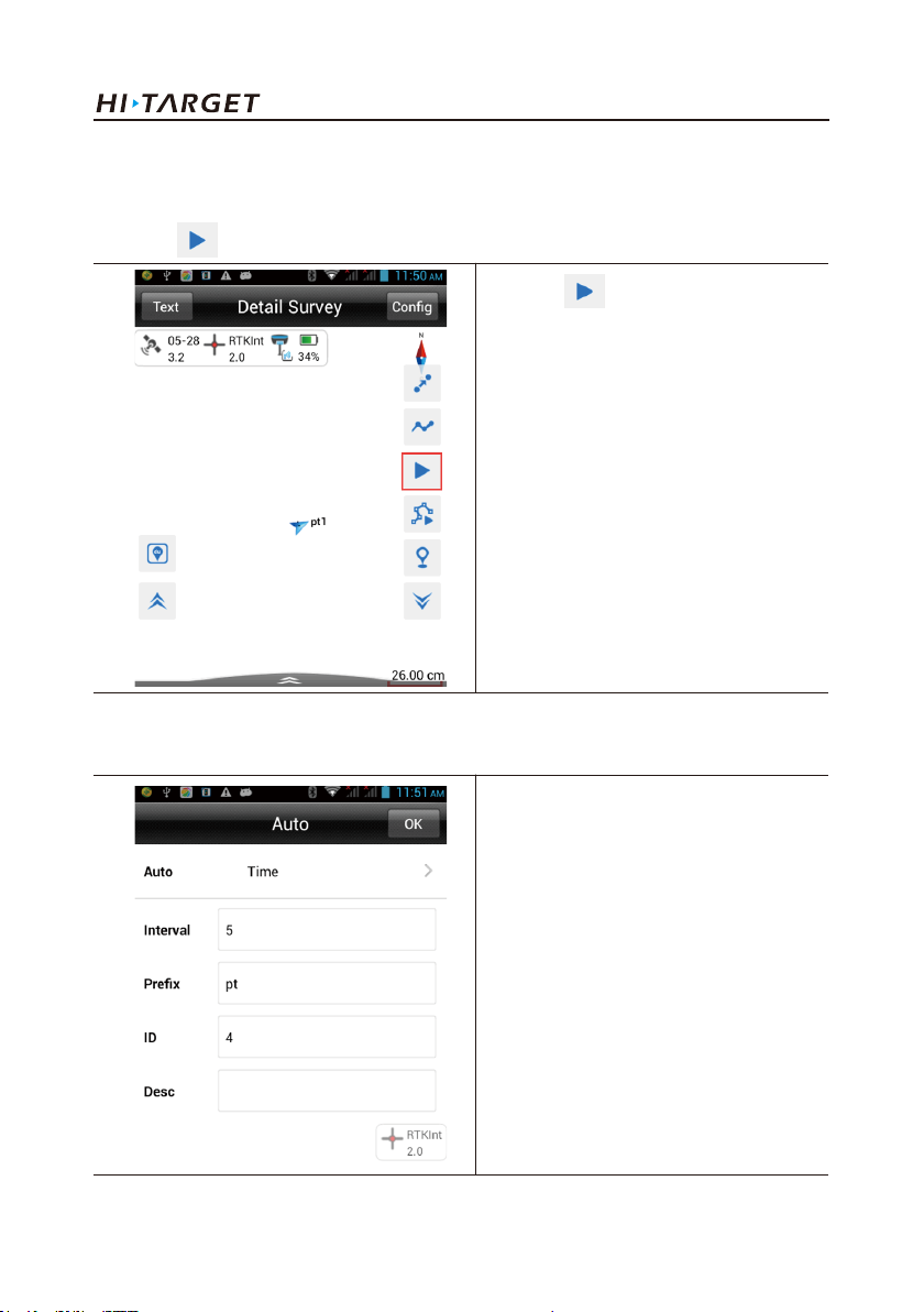
3. Automatic collection
Automatically record measurement point according to the configured record condition.
(1) Click " "
(2) Collection setting, including sampling interval (time or distance), point name and number, etc.
(user-defined available)
Click" "to start automatic
collection
Auto: Time, Dist, Slant Dist for
optional
Interval: Sampling
interval(Determined as needed)
Prefix: Prefix of name point
(user-defined available)
ID: Start number of point
Desc: Description
81

Hi-Survey
(3) Click "OK" to start collection
Click "OK" to start collection
The collected point can be stored
automatically.
82

V60 Getting Started
(4) Click " " to stop automatic collection;
4. View all collected points
(1) Click "Project->Points" in the software main interface
Click " " to stop automatic
collection;
Click "Project"->Points
83

3.3 Export of data achievement
Hi-Survey
Inquire the point library
Data achievement export supports the following format: *.txt, *.CSV, *.dxf, (shp File)*.shp and
(Excel File)*.csv.
The export procedures are as follows.
(1) Project->Data Transfer
84

(2) Select "Export".
V60 Getting Started
Click" Data Transfer"
Select "Export"
85

Hi-Survey
(3) Define name of file exported -> select saving path;
Input name of file->select output
format->select saving path
Export format of file
includes(8kinds):
User-defined(*.txt),
User-defined(*.CSV),
dxfFile(*.dxf),
shpFile(*.shp),
Excel File(*.CSV),
South cass7.0(*.dat),
Scsg2000(*.dat),
PREGEO(*.dat).
86

V60 Getting Started
(4) Select file format (take *.dxf for example) ->click "OK" to complete data export.
87

Hi-Survey
3.4 staking out
lofting, also called staking-out, refers to mark the plane position and elevation of buildings and
structures planned and designed on the design drawing on the ground with certain measuring method
according to required precision as the basis of construction.
Confirm coordinate system of staking out coordinate file before staking out and if coordinate system
is inconsistent, the staking out will fail.
●Stake line
Procedure:
1. Click "Survey"->Stake Points (Enter into stake point interface)
Click "Survey" and select "Stake
Points" (Enter into stake point
interface)
88

2. Click" "(enter into point selection interface)
V60 Getting Started
Enter into "Stake Point" interface
Click '' ''
89

Hi-Survey
Enter into stake point selection
interface
2. This step has three point selection methods (Choose either), namely, A. Input coordinate; B.
Select from coordinate library; C. Select from graph.
A. Directly input coordinate
1) Input "Name"->Input NEZ coordinate->Click "OK"
90
Input the point’s name and
coordinate, tick "Save to Stake Pts
Lib "to save the coordinate of input
point into the stake point library.

V60 Getting Started
2) Add the input coordinate point to "Stake points list"->Click "OK" to start stake.
Start staking-out
Stake interface
Backward: Southward
Towards the Right: Eastward
Delta H: Altitude difference between
stake coordinate and actual position
Name : name of stake point
σ: Relative precision
HD: Horizontal Distance
91

Hi-Survey
B. Select from coordinate library;
1) Input keyword of point name ->click " "->Coordinate point->select coordinate point;
Input keyword of point name (look
up keyword of point name)
Click " " to jump into point
library
92
Jump into point library and select
coordinate point.

V60 Getting Started
2) Tick Save to stake Pts Lib->Click "ok"
3) Input keyword->Click " " of point name in "Name"
Tick Save to stake Pts Lib->click
"ok", add the coordinate point from
the point library to the stake point
library.
Input keyword of "Name"
93

4) Start staking-out
Hi-Survey
Inquire result, select the required
point and click "OK" to start stake.
94
Start staking-out

V60 Getting Started
Stake interface(indicate position of
target point)
Backward: Southward
Towards the Right: Eastward
Delta H: Altitude difference between
stake coordinate and actual position
Name : name of stake point
σ: Relative precision
HD: Horizontal Distance
C.Select from graph;
1) Click " "Select stake point on Map. Click " ", the software can extract the coordinate
of stake point library automatically in the positive sequence or negative sequence for stake.
Click " "
95

2) Click "OK" to start staking-out
Hi-Survey
Select stake point on Map
96
Start staking-out

V60 Getting Started
Stake interface (indicate position of
target point)
Backward: Southward
Towards the Right: Eastward
Delta H: Altitude difference between
stake coordinate and actual position
Name: name of stake point
σ: Relative precision
HD: Horizontal Distance
●Stake line
1. Click "Survey"->"Stake Line"->Click" " to enter into the stake line interface; Click
"Survey"->"Stake Line"
Click "Survey"->"Stake Line"
97
 Loading...