

Page 1

V100 GNSS RTK System
Getting Started
Hi-Target
Co., Ltd
All Rights Reserved
Surveying Instrument
V100 GNSS RTK System Getting Started
Page 2

Page 3

Ⅰ
Content
1. Products Introductions
1.1 Hardware structure
1.2 Power supply system
1.3 Button operation
1.4 LED
1.5 Handheld controller iHand20
2. Technical Parameters
3. Work Modes Introdution
3.1 Static mode
3.1.1 Static data collection
3.1.2 Static data storage and download
3.2 Network rover mode
3.2.1 Project setting
3.2.2 Data collection
3.2.3 Stake out
3.2.4 Data export
3.2.5 Auto-backup and quickly recover
3.3 Base mode with external radio
------------------------------------------------------------------------------ 3
-------------------------------------------------------------------------------- 4
---------------------------------------------------------------------------- 5
---------------------------------------------------------------------------------- 9
--------------------------------------------------------------------------------------------------- 10
------------------------------------------------------------------ 12
--------------------------------------------------------------------------- 19
--------------------------------------------------------------------------- 24
---------------------------------------------------------------------------------------- 25
------------------------------------------------------------------------- 25
--------------------------------------------------------- 26
--------------------------------------------------------------------------- 28
---------------------------------------------------------------------------------- 28
---------------------------------------------------------------------------------- 42
-----------------------------------------------------------------------------------------48
-------------------------------------------------------------------------------------- 54
----------------------------------------------------------55
-------------------------------------------------------------- 57
V100 GNSS RTK System Getting Started
Page 4

Ⅱ
4. Trouble Shooting
4.1 Registration procedure
4.2 Firmware upgrade
4.3 Reset operation
Schedule1 factory default parameters
Schedule2 key accessories information
------------------------------------------------------------------------------------ 59
-------------------------------------------------------------------------- 60
-------------------------------------------------------------------------------- 62
----------------------------------------------------------------------------------- 63
------------------------------------------------------------63
-------------------------------------------------------- 64
V100 GNSS RTK System Getting Started
Page 5
1
Exclusion
Before using the products, please carefully read the operating instruction, and it will help you better
use the product. Hi-Target Surveying Instrument Co., Ltd will not assume the responsibilities if you
fail to operate the product according to the requirements in operating instruction, or operate the
product wrongly because of failing to understand the operating instruction.
Hi-Target is committed to constantly perfect product functions and performance, improve service
quality and reserve the rights to change the contents in operating instruction without separate notice.
V100 GNSS RTK System Getting Started
Introduction
Welcome to use Hi-Target V100 receiver, this introduction is applicable to Hi-Target V100 products.
The introduction describes how to install, set and use V100 products.
Experience requirement
In order to help you use Hi-Target series products better, Hi-Target suggests you carefully reading
the instruction. If you are unfamiliar with V100 products, please refer to www.hi-target.com.cn
Tips for safe use
Warning: The contents here generally are very important. Such wrong
operation may make the machine damaged, make the data lost, even
breaks down the system and endangers personal safety.
Notice: The contents here generally are special operations, needing
your special attention. Please read the contents carefully.
Preface
Page 6

2 2
We have checked the consistency between contents in instruction and software & hardware, without
eliminating the possibility of deviation. The pictures in operating instruction are only used for
reference. In case of inconformity with products, the products shall prevail.
Relevant information
You can get this introduction in the following ways:
1.After purchasing Hi-Target V100 receiver, there will be “V100 GNSS RTK System Getting
Started” in the instrument container to guide you how to operate instrument.
2.Log in Hi-Target official website, download the electronic version introduction in “Download
Center” → “Manual” → “Surveying Products”
Technology and service
If you have any technical issues, you can call Hi-Target technology department for help, we will
answer your question in time.
Advice
If you have any advice or suggestion on V100, please call us or Dial the national hotline: +86
400-678-6690. Your feedback information will improve the production quality.
V100 GNSS RTK System Getting Started
Page 7

3
Products Introductions
■ Hardware structure
■ Power supply system
■ Button operation
■ LED
■ Handheld controller iHand20
C
C
C
C H
H
H
H A
A
A
A P
P
P
P T
T
T
T E
E
E
E R
R
R
R
1
V100 GNSS RTK System Getting Started
Page 8
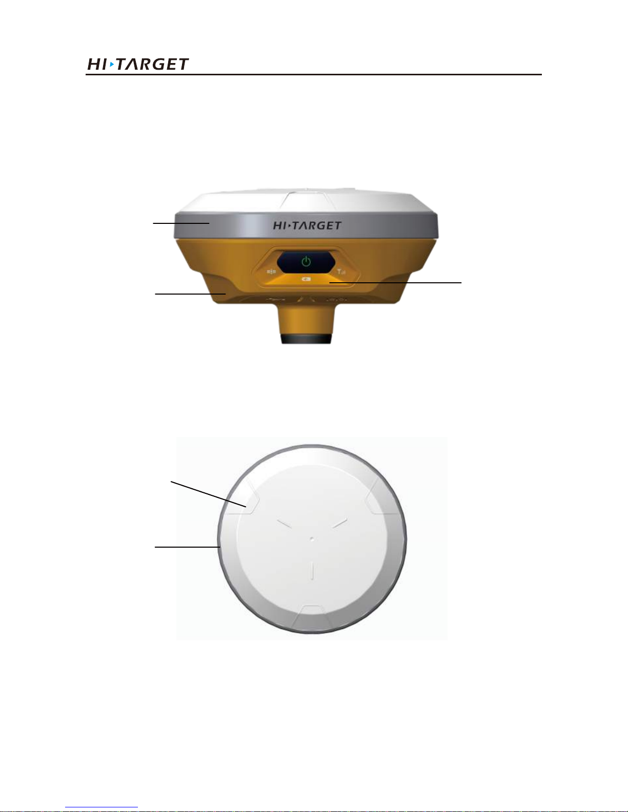
1.1. Hardware structure
Figure 1-1-2
Figure 1-1-1
4
Raised point
Guard collar
The product appearance is divided into three parts, upper cover, bottom cover and control
panel.
Upper cover
Bottom cover
Control panel
Products Introductions
Page 9
1.2. Power supply system
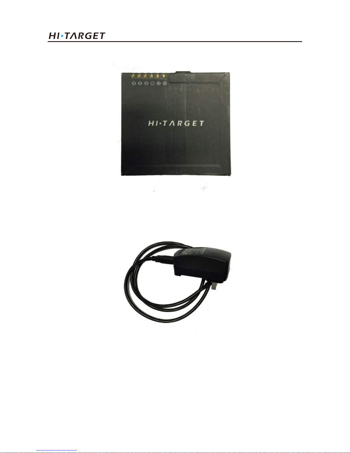
Battery, adapter type
Name Type
lithium battery BLP-6300S
Power adapter PSAI10R-050Q
5
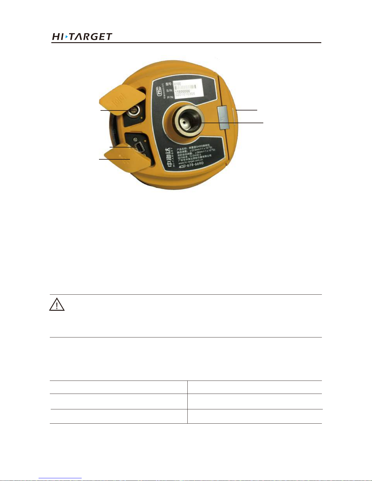
Five-pin socket
Mini USB socket
Protective plug
Battery compartment
Connection screw
Figure 1-1-3
Notice:
If it is unnecessary to use five-pin socket, and USB interface, please cover the rubber plug to prevent
dust.
◆ Connection screw: for the instrument fixed to the base or the pole.
◆ Battery compartment: for housing lithium battery.
◆ Five-pin socket: for external data linking and external power supply.
◆ Mini USB socket: for connection to the host and external devices, upgrade firmware and
download the static data, can also charge or supply electricity to the host.
◆ Protective plug: for dustproof and waterproof.
V100 GNSS RTK System Getting Started
Page 10
Recharge
V100 lithium battery should be charged by PSAI10R-050Q adapter, about 7 hours of charging time.
Lithium battery
Figure 1-2-1
Figure 1-2-2
6
Adapter
Products Introductions
Page 11
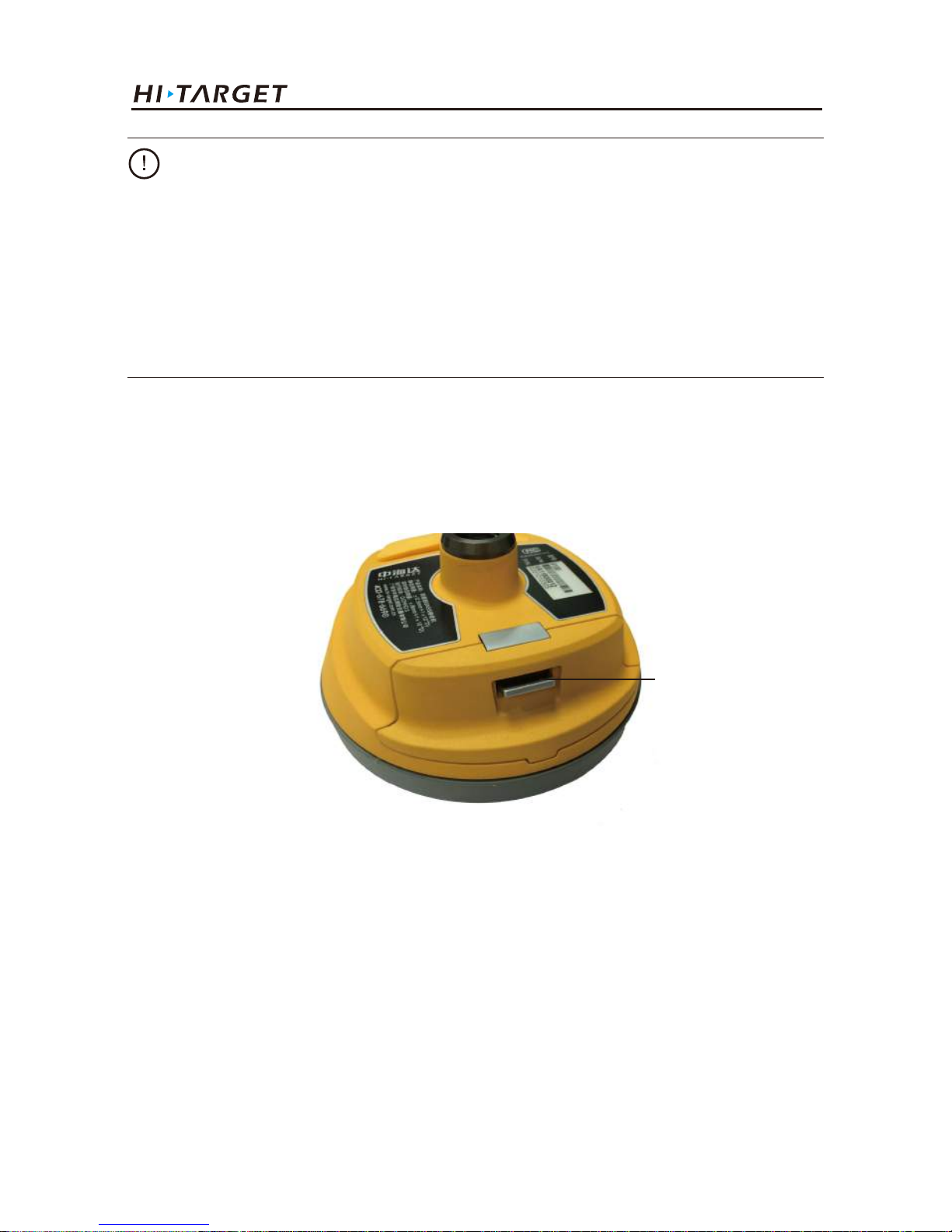
Battery installation and removal
(1) Push up the battery cover button, open battery cover.
(2) Align battery pole with battery compartment pole, push the battery to the end and the mental
button will upspring.
Figure 1-2-3
Battery cover button
7
Warning:
1. Only the battery and charger configured by the manufacturer can be used; the battery must not be
thrown into fire or used in metal short circuit electrode.
2. Stop using when the battery is heating, deformation, liquid leakage, smelling or other abnormal
reactions, please exchange new battery.
3. Stop using when the battery’s working time has been Significantly reduced, the battery is aged,
please exchange new battery.
V100 GNSS RTK System Getting Started
Page 12
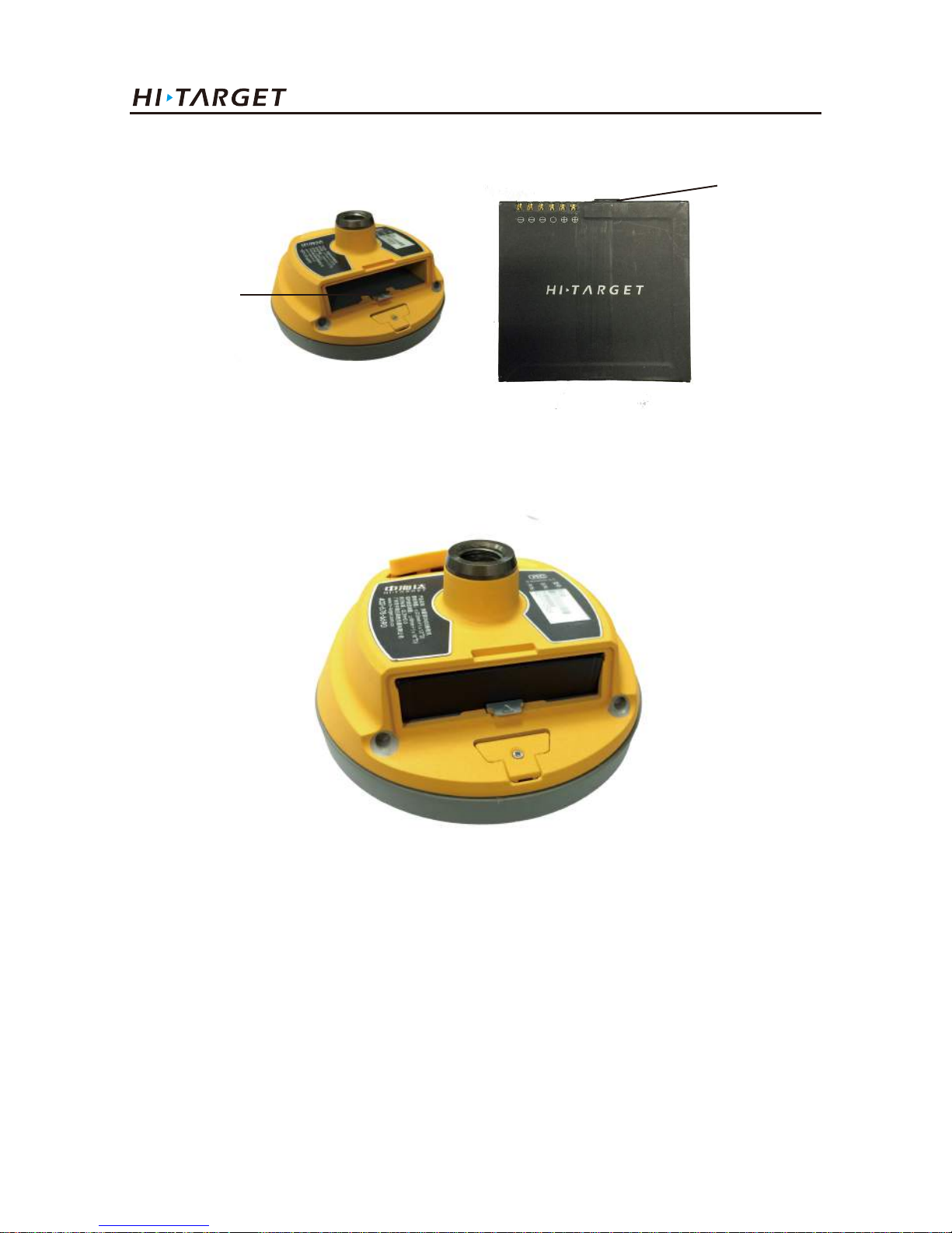
8
Metal button
Battery pole
Figure 1-2-4
Figure 1-2-5
(3) Close the battery cover.
Removal
Push up the battery cover button to open it, then press the metal button and remove battery.
Products Introductions
Page 13
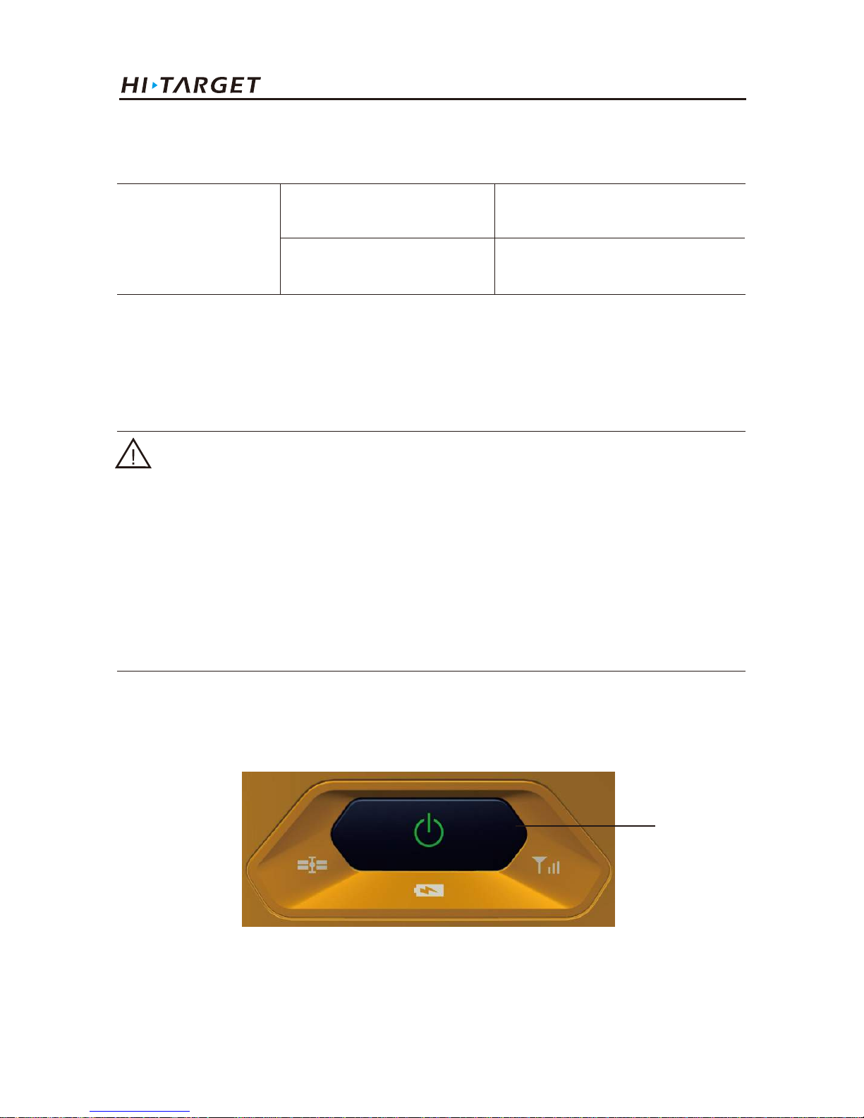
1.3. Button operation
9
Power supply
Power supply mode
Power supply mode
Power supply
External power supply request
Internal:lithium battery
External:USB, Five-pin socket
USB socket:DC power 4.2-5.5V/1.5A
Five-pin socket:DC power 6-28V/1A
When external power supply , the host will automatically detect the voltage of lithium battery and external
power supply , and choose the higher voltage power. As for external power supply, it shall use the special
power specified by Hi-Target.
Power button
Figure 1-3-1
Most settings and operations of receiver are completed using a button on control panel.
Notice:
1. The service time of lithium battery will decrease along with the decrease in temperature and
charging-discharging times increasing. A new 6300mAh lithium battery can be used for 7 hours of
static data collection or rove work.
2. Please charge the battery within 24 hours after using up, to extend the service life of battery, or
the battery performance will be damaged.
3. If the battery won't be used for long times, please charge once every month to extend the service
life of battery.
V100 GNSS RTK System Getting Started
Page 14
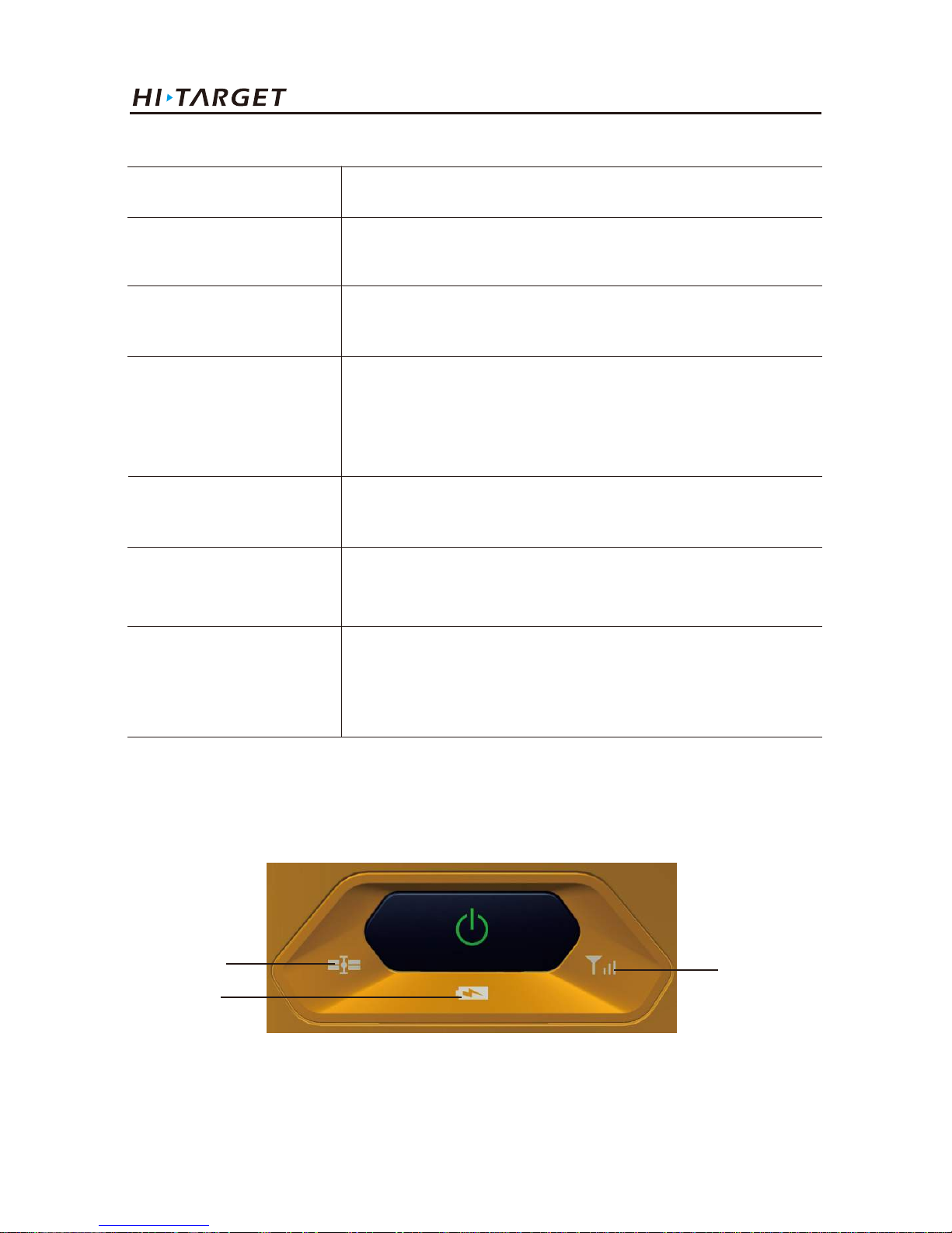
10
Description of power button operation
Operation name
On
Off
Automatic setting station
Operating mode switching
Status inquiry
Reset motherboard
Description
Shutdown status, long press the button one second to boot,
all lights are on
Boot status, long press the button three seconds, all lights
double fast flash, release the button
Shutdown status, long press the button six seconds, all lights
double fast flash, release the button, the instrument will
automatically set the base station
Double-click the button to switch working mode, double-click
each time to switch between static and RTK mode
Click power button, power LED flashing times displays
power
Boot status, long press the button more than six seconds, all
lights flash at the same time, release the button, it will reset
motherboard
1.4. LED
To indicate different status under different work mode.
Satellite LED
Power LED
Network LED
Figure 1-4-1
Products Introductions
Page 15
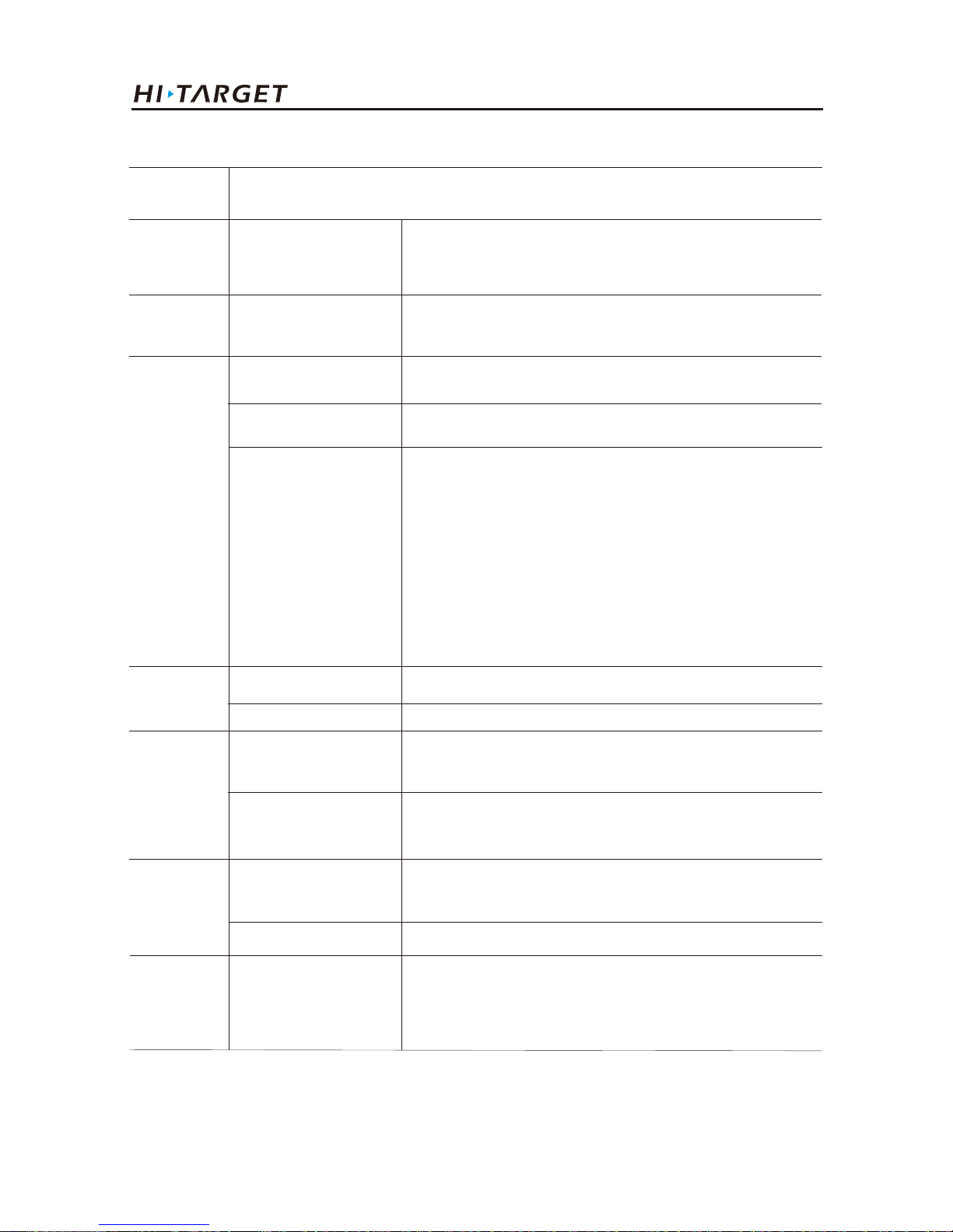
LED Function Description
LED
Power LED
(Green)
Power LED
(Yellow)
Power LED
(Red)
Long-term lighting
Long-term lighting
Long-term lighting
Slow flash
Fast flash
Meaning
Full battery
Full battery voltage: internal battery≥3.9V(100%
power)
Normal voltage: 6% <internal battery power ≤99%
Low voltage: internal battery≤5%
Power indication: 1-4 flash per minute under the
direction of electricity
1:0%~25%
2:25%~50%
3:50%~75%
4:75%~100%
Network LED
(Green)
Network LED
(Red)
Satellite LED
(Green)
Three LEDs
Off
Long-term lighting
Slow flash
Fast flash
Long-term lighting
Slow flash
Fast flash
Static mode
RTK mode
Static mode, storage space<10MB
Satellite lock
satellites are lost
Satellite LED, Network LED, Power LED all fast flash
at the same time, when release power button, the
motherboard will be reset.
1. RTK mode: flash as difference data interval
2. Static mode: flash as sampling interval
11
V100 GNSS RTK System Getting Started
Page 16
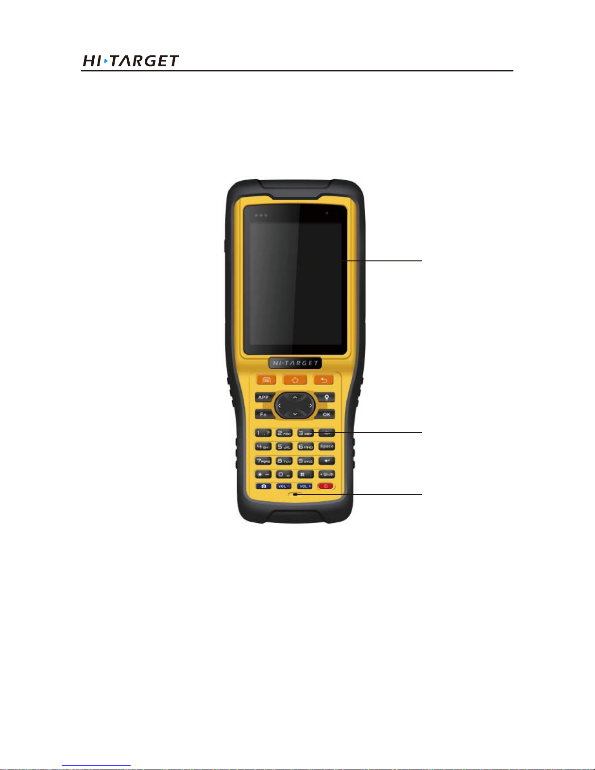
12
Front of handheld controller
The front of iHand20 handheld controller includes touch screen, keyboard and microphone
Touch screen
Keyboard
Microphone
Figure 1-5-1
1.5. Handheld controller iHand20
◆ Touch screen: Multipoint capacitive touch screen with touch pen, which supports Chinese and
English input.
◆ Keyboard: Photograph, direction control, switch between Chinese and English, data collection,
volume control, power on, power off and other functions.
◆ Microphone: Internal microphone can be used for field collection of voice message.
Products Introductions
Page 17
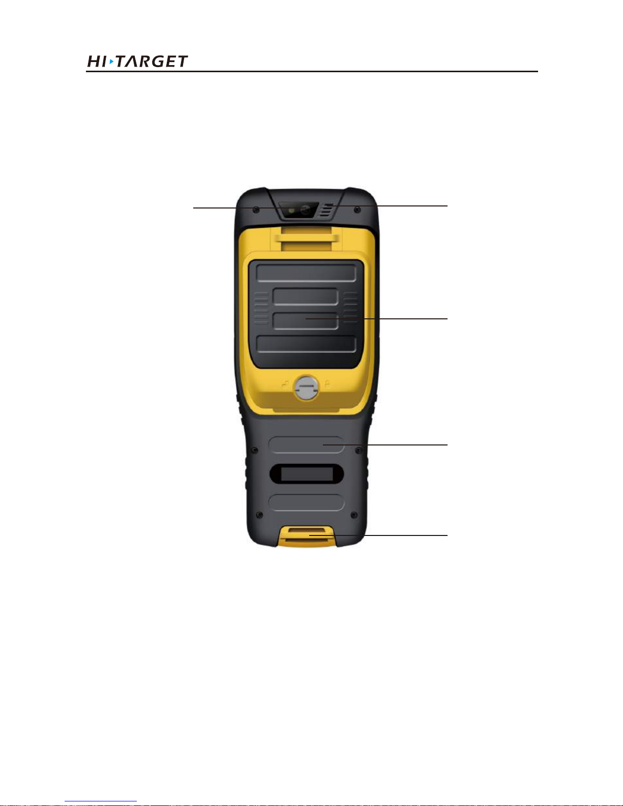
Reverse side of handheld controller
There are camera, battery cover, belt, speaker, etc. on the reverse side of iHand20 handheld
controller.
Camera
Speaker
Battery cover
NFC module
Belt
Figure 1-5-2
◆ Camera: Used for field collection of image information.
◆ Battery cover: Internal removable lithium battery.
◆ Belt buckle: Connect the belt to prevent sliding down.
◆ Speaker: Conduct real-time voice broadcast for the instrument operation and status.
13
V100 GNSS RTK System Getting Started
Page 18
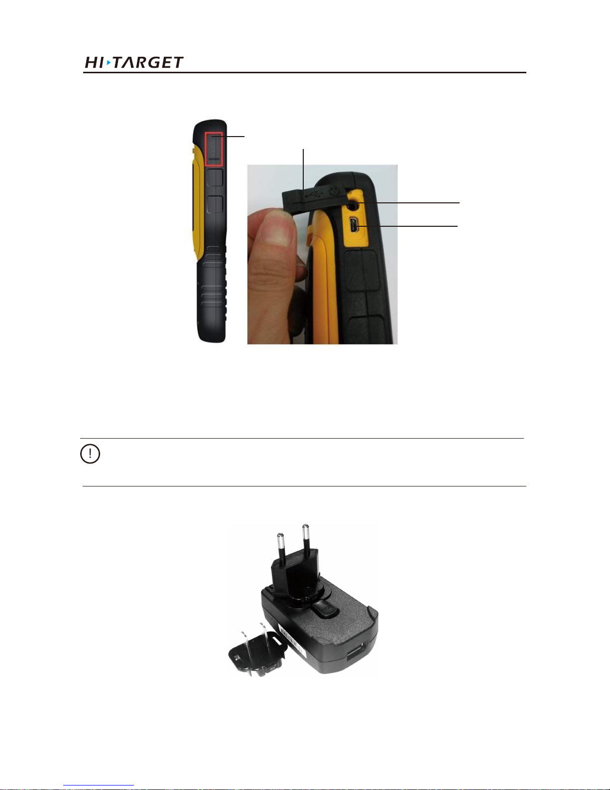
14
Figure 1-5-4
◆ Mini USB: Used for connecting USB data line and iHand20 handheld controller.
◆ Audio port: Used for connecting headphone cable and iHand20 handheld controller.
Warnings: In case of not using audio port or Mini USB, please close the rubber cover so as to
achieving waterproof and dustproof.
Handheld controller accessories
Charger
Side of handheld controller
Figure 1-5-3
Mini USB
Audio port
Products Introductions
Waterproof & dustproof rubber cover
Page 19
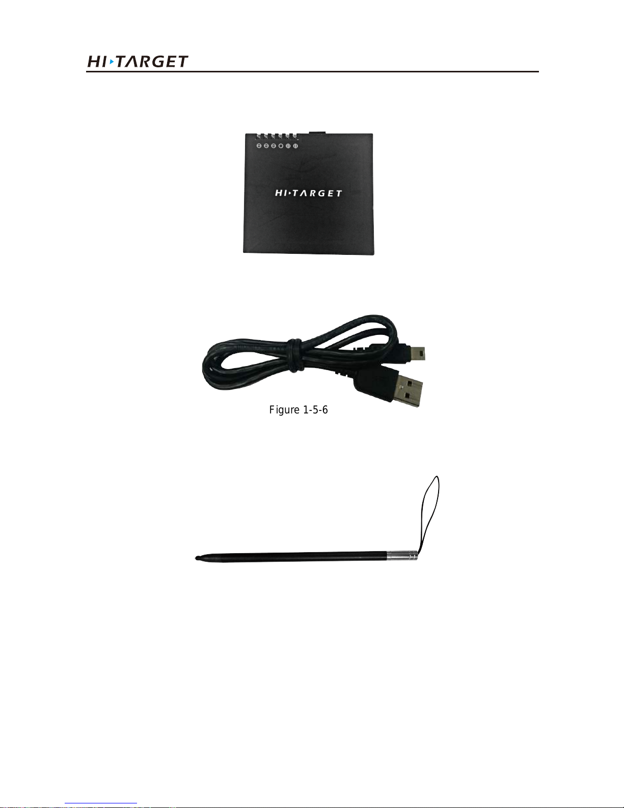
Figure 1-5-5
Figure 1-5-6
Battery (Lithium battery: 3.7V /6300mAh)
Data line
It is used for changing and exchanging data between computer.
Touch pen
To use the touch pen to operate the handheld controller, it is required to start the function of
"handwriting pen", and open the handheld controller’s [system setting] → [auxiliary function] →
check [handwriting pen]
Figure 1-5-7
15
V100 GNSS RTK System Getting Started
Page 20
16
Figure 1-5-8
Operation of handheld controller
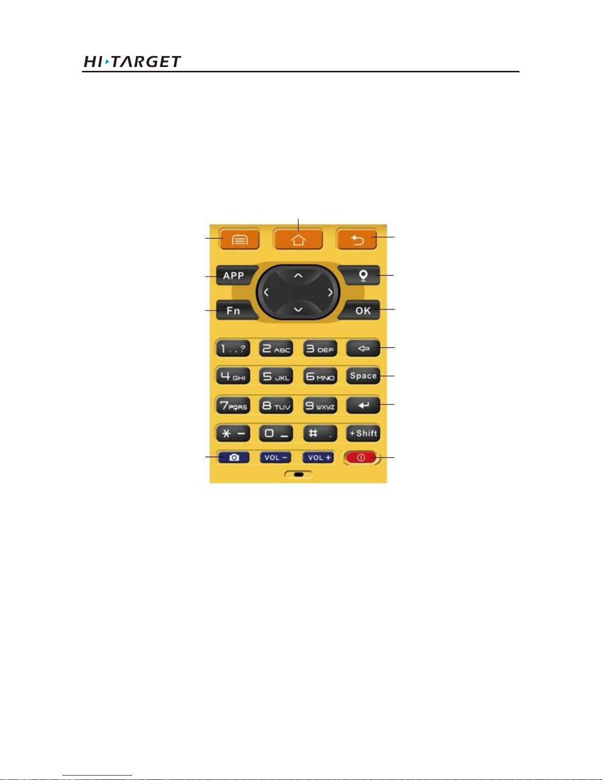
Keyboard
Most settings and operations of Hi-Target iHand20 handheld controller can be completed by the
touch pen, and commonly used operations can be completed by keyboard. Appearance and
functions of keyboard are introduced briefly as follows.
Keyboard include: Back, OK, Power, APP, Fn, Collect, Camera, etc. on button board of iHand20.
Back: Delete or exit the operation of current window.
OK: Confirmation.
Power: Press it for above 3s for power on/ power off. Under the power on status, press power button
for 1s to turn off / turn on the screen backlight.
Back
Collect
OK
Del
Space
Enter
PowerCamera
Fn
APP
Menu
Home
APP: Quick start of Hi-Survey software, press button APP for a long time for the Road popup, then
select "Hi-Survey Road" and click [Ok]. And the software selected this time can be started quickly
only by pressing key APP next time.
Products Introductions
Page 21
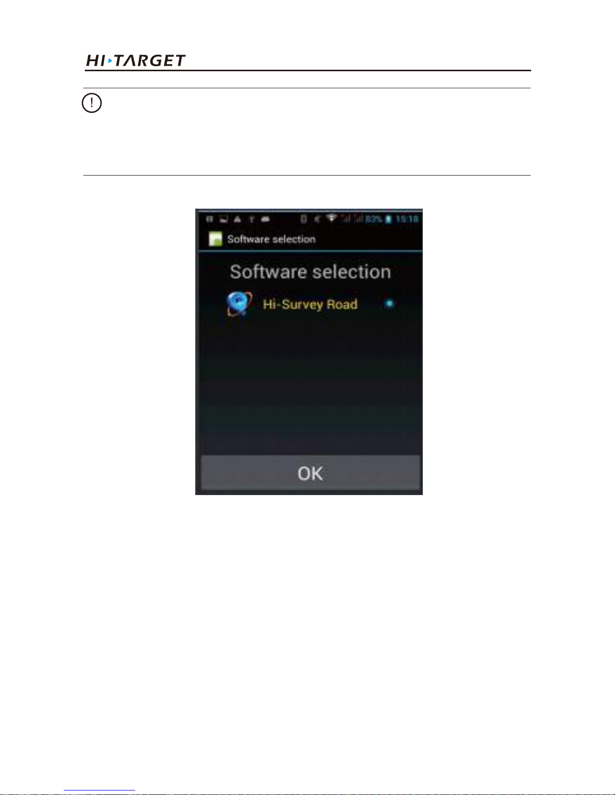
Figure 1-5-9
Fn button: Press Fn button for 3s and popup interface of software switching so as to achieve fast switch
of input method. In case of [physical button input method], only press Fn button to switch over input
methods of Chinese Pinyin ,strokes, digitals and letters under input status.
Collect button: Collect data by manual operation.
Camera button: Press it for a short time to enter into photograph interface; Press it for 3s on the
non-camera interface to start up/shut down flashlight function.
Screenshot: Press "VOL-" and power button simultaneously for 3s, screen capture will be kept in the file
of "Mobile phone storage→ Pictures→ Screenshots".
Cautions:
When installing Hi-Survey Road for the first time, it is necessary to press button APP for 3s for
software quick start selection settings. Otherwise, corresponding software cannot be started quickly
by only pressing button APP.
17
V100 GNSS RTK System Getting Started
Page 22

18
Data download
1. Connect handheld controller to computer by USB data line, and pull down the notice column and
click USB computer connection [open USB storage].
2. If it is required to synchronously operate handheld controller or install and use third-party
software to debug data on the computer, "USB debugging" function shall be ticked. Turn on the
handheld controller, and click [System Settings] → [Developer options] → [USB debugging] on the
desktop menu.
3. In the popup debugging window, click [OK] to complete the connection between handheld
controller and computer.
4. In the computer, file operations between handheld controller and computer can be conducted by
[Portable Devices].
Cautions:
1. When the iHand20 handheld controller is not used in the work, please turn off the backlight for
saving electric quantity and prolonging the working time.
2. Only the image collection interface supports the shortcuts operation. In order to avoid the input
conflict of input box, the text interface does not support shortcuts operation.
(1)Average collection shortcut is Buttton "7";
(2) Indirect measurement shortcut is Button "8".
Products Introductions
Page 23

C
C
C
C H
H
H
H A
A
A
A P
P
P
P T
T
T
T E
E
E
E R
R
R
R
2
Technical Parameters
19
V100 GNSS RTK System Getting Started
Page 24
20
GNSS configuration
Table 1 GNSS configuration
System core
Channel
BDS
GPS
GLONASS
GALILEO
Output format
Difference support
RTK positioning accuracy
Static, rapid static accuracy
Initialization time
Initialization reliability
Data update rate
International first-class PCC new efficient intelligent real-time
core
220
B1, B2
L1 C/A, L2E, L2C, L5
L1 C/A, L1 P, L2 C/A(Limited GLONASS M and L2P)
Upgrade reserve
ASCⅡ:NMEA-0183 and binary : Trimble GSOF
sCMRx, CMR, CMR+, RTCM2.1/2.2/2.3/3.0/3.2
Plane:±(8mm+1×10⁻⁶D)
Height:±(15 mm+1×10⁻⁶D)
Plane:±(2.5 mm+1×10⁻⁶D)
Height:±(5 mm+1×10⁻⁶D)
Code difference:0.4m
SBAS difference:1.2m
Typical 8s
>99.9%
<20Hz
Technical Parameters
Page 25

Electric characteristics
External interface
Control panel
Built-in communication
System configuration
Physical characteristics
◆ Core control chip CotexA8, built-in 16GB Flash memory
◆ Size: 127.5mm×57mm
◆ Weight: ≤700g (including battery)
◆ Material: magnesium alloy
◆ Operation system:intelligent real-time system
◆ Boot time: 1s
◆ Data storage:built-in 8GB storage
◆ Battery: high capacity lithium 6300mAh/3.7V, removable, continuously operating time
reaches above 7 hours
◆ Voltage: USB interface: DC 4.2-5.5V/1.5A; five-pin interface: DC6-28V/1A
◆ Power consumption: 3.2W
◆ NFC near field communication
◆ Dual mode Bluetooth communication
◆ Panel: one button
◆ Indicator:three bi-color LED lights
◆ 1 USB socket
◆ 1 five-pin socket
21
V100 GNSS RTK System Getting Started
Page 26

22
The receiver shall operate in dry working environment regardless of waterproof materials. In order
to advance the stability and service cycle of receiver, the receiver shall be prevented from extreme
environment, such as:
The cloud service supports for 24 hours, realizes integrated technique of indoor work and field work,
remote manage serve and support equipment. It manages team project, shares parameters and control
points, post backs real-time verify and note track of result data by cloud background. After the user’ s
authorization, terminal servers can remotely provide customers with technical support, including
system version upgrading, system registration, remote debugging and other services.
Environmental requirements
Private cloud service
Environment characteristics
◆ Moisture
◆ Temperatures above 65 degrees centigrade
◆ Below - 40 degrees centigrade
◆ Corrosive liquids or gases
◆ Protection class:IP67; protect 2m temporary soaking underwater, completely prevent dust
◆ Shock-proof: Anti 2 m natural fall
◆ Working temperature: -40 ℃ ~ 65℃
◆ Storage temperature: -40℃~75℃
◆ Relative humidity: 100%, anti-condensation
Technical Parameters
Page 27

Electronic jamming
The receiver shall not be installed in the place near to strong electric power and interference signal,
such as:
◆ Oil duct (spark plugs)
◆ Telvision and computer display
◆ Generator
◆ Battery-operated motor cycle
◆ DC-AC power supply changeover equipment
◆ Fluorescent lamp
Power supple
23
V100 GNSS RTK System Getting Started
Page 28

24
Work Modes Introducation
■ Static mode
■ Network rover mode
■ Base mode with external radio
Work Modes Introduction
C
C
C
C H
H
H
H A
A
A
A P
P
P
P T
T
T
T E
E
E
E R
R
R
R
3
Page 29
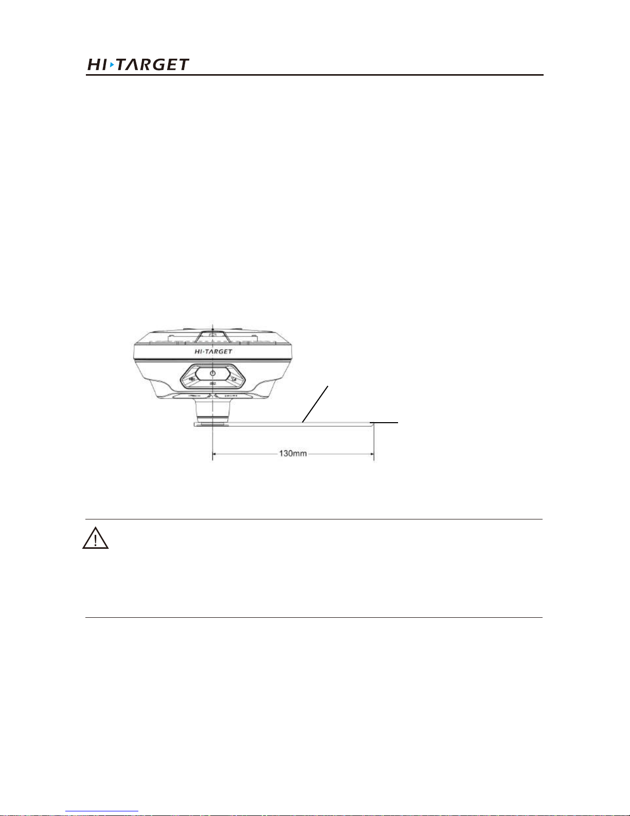
25
Notice:
1). Instrument height should be measured from control point to the height measurement point of the
measurement reference bench.
2). The measurement reference bench radius is 0.130 meter.
3. Record point name, receiver S/N, receiver height, beginning time.
4. Press power button to power on and double click power button to set static collecting mode.
V100 GNSS RTK System Getting Started
3.1. Static mode
3.1.1. Static data collection
V100 GNSS Receiver can collect static data. Relative operations are as below.
1. Set up receiver on a control point, centering and leveling strictly.
2. Measure the height of receiver for three times, on condition that the difference of each measuring
is less than 3mm and the final height of the receiver should be the average height. Below is the
schematic.
Figure 3-1
Measurement reference bench
Height measurement point
Page 30
26
Notice:
When the receiver storage space is less than 10MB, data light (red) fast flash, and it stop recording
data, the existing data files will not be overwritten.
Notice:
The satellite LED flashing means the receiver is searching the satellites. The satellites are fixed once
the satellite LED stays light on. Network LED flashes due to your collection interval set, which
means an epoch will be collected every flash.
5. Turn off the receiver after static data collected and record the turn off time.
6. Download and post-process static data.
Caution:
1) Don’t move the tri-branch or change the collecting set while the receiver is collecting data.
2) V100 GNSS receiver doesn’t support recording Rinex format data.
Work Modes Introducation
3.1.2. Static data storage and download
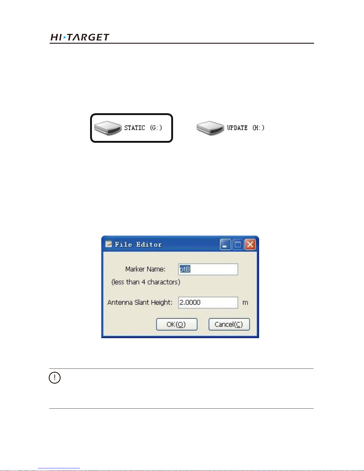
Collected GNSS static data is stored in "static" disk that 8GB internal storage of V100 receiver,
effective storage space is 6.6GB, includes two folders: log and gnss, log folder stores log
information, the data format storage in gnss folder is * .gns. You can connect the receiver to
computer through USB data cable, copy static data to your computer like using a U disk.
Figure 3-2
Page 31
Caution:
It only supports copy procedure when connected to computer. Deleting static files and formatting
disk can be only operated by handheld software.
27
V100 GNSS RTK System Getting Started
The receiver can download data like U disk , it need Mini USB data cable, one end of Mini USB data
cable is connected to computer USB port and the other end is connected to Mini USB port of
receiver. It will appear “static” disk after being connected,then open the disk, copy the collected
static files to computer’s hard disk.
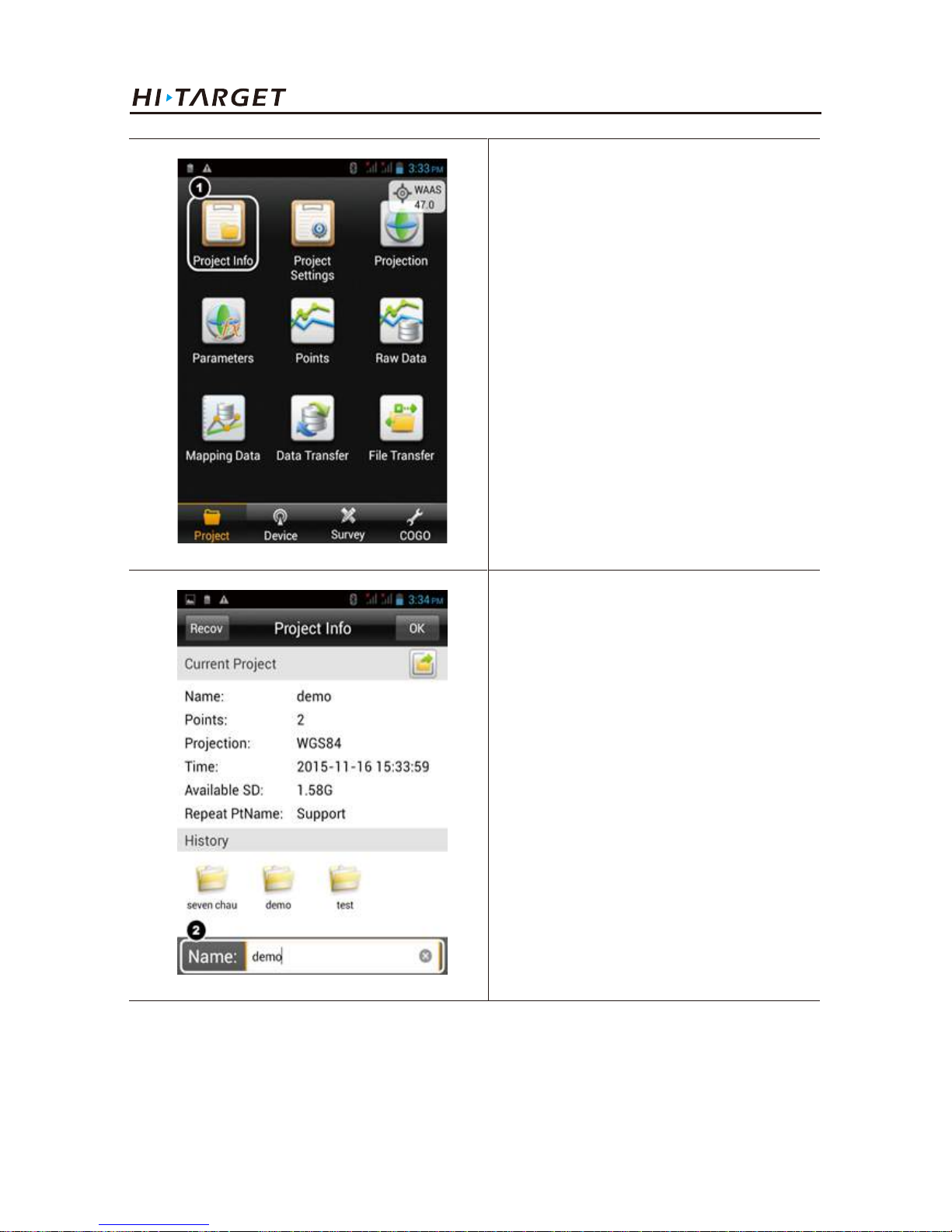
The steps of modify point name and antenna height of downloaded static file are:
1. Choose *. GNS files and double click the mouse.
2. Modify point name and input antenna height in the popping up dialogue of “file edit”, and then
click “OK”.
Figure 3-3
Figure 3-4
Page 32

28
Work Modes Introducation
After new project is built before the measurement, the collecteddata will be saved in the project.
When building new project, relevant setting needs to be conducted, for example, setting of project
information, and coordinate system, etc...
3.2. Network rover mode
Pair with the powerful surveying software Hi-Survey, the intelligent V100 GNSS receiver will turn
into a portable network rover.
The main operating procedures in brief:
◆ Project setting
◆ Data collecting
◆ Staking out
◆ Data exporting
1. New project
3.2.1. Project setting
New project
Project settings
Device connecting
Rove settings.
Page 33
29
V100 GNSS RTK System Getting Started
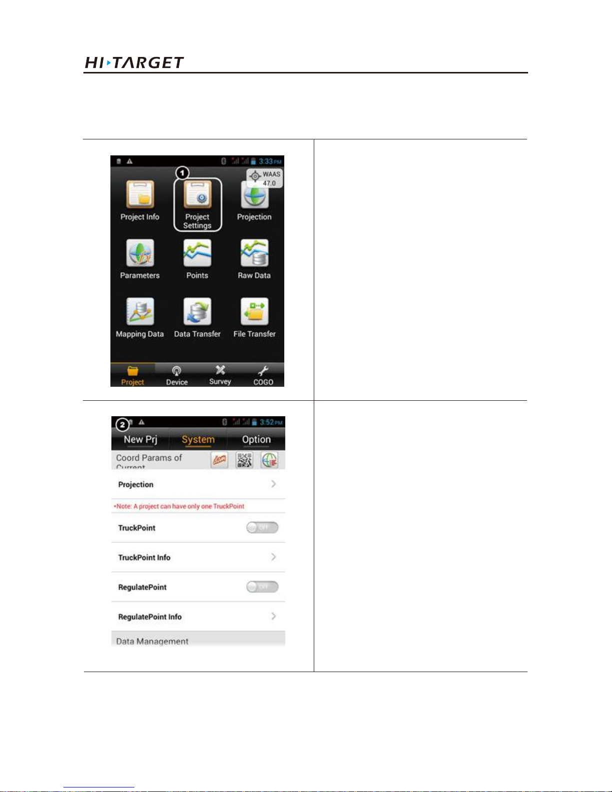
Project settings include coordinate system and other parameters settings.
2.Input project name.
(Note: The name of new project shall
not be the same as the name of old
projects.)
1. New project can be built and the
existing project can be opened or
deleted.
2. Project settings
Page 34
30
Work Modes Introducation
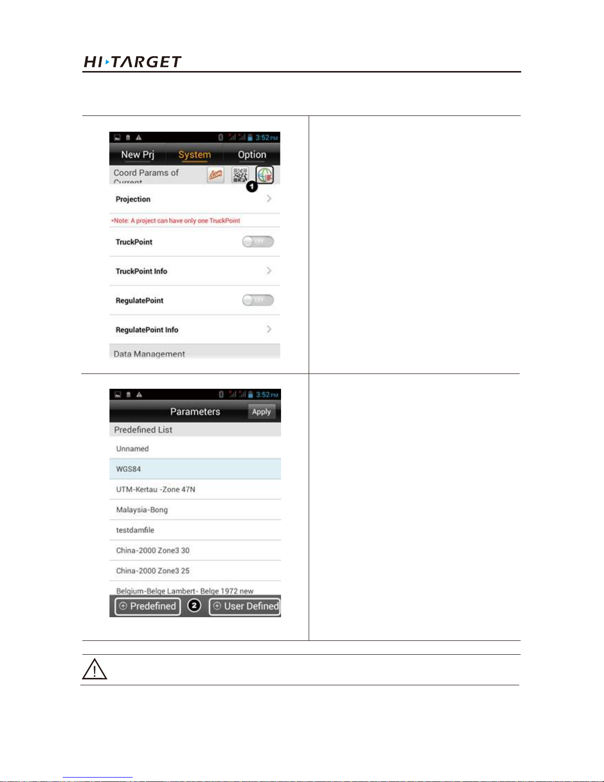
For measurement, coordinate system must be configured, because it is related to the accuracy of
coordinate. There are two methods to set the coordinate system.
1. Click Project Settings:Including
settings of project and coordinate
system information.
2. Settings interface.
Page 35
31
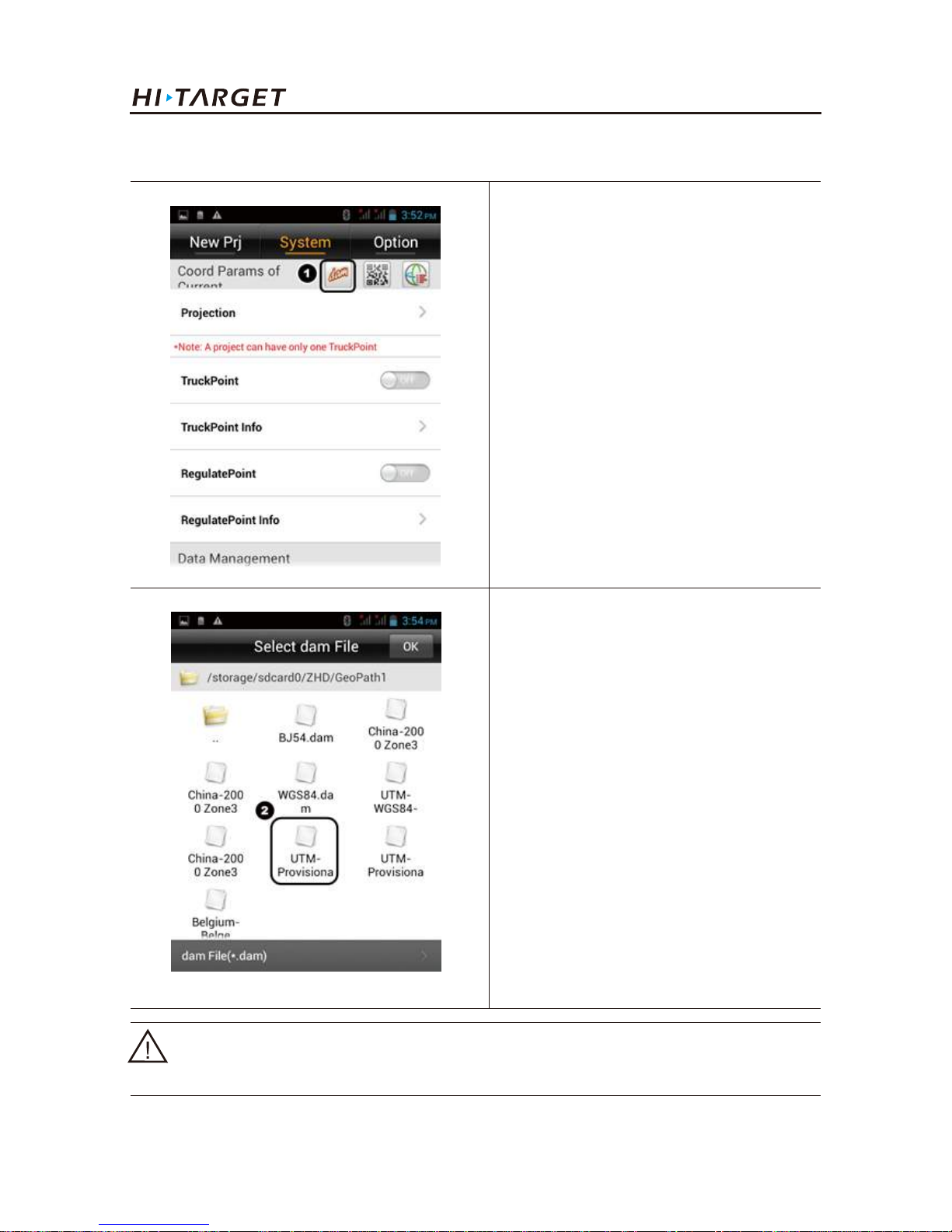
1. Click ① to enter into the setting
interface.
2. Select a coordinate system from
“Predefined” or build by User Defined.
(1) Build a coordinate system
Notice: Any question about “User Defined” pleases contact technical support.
V100 GNSS RTK System Getting Started
Page 36
32
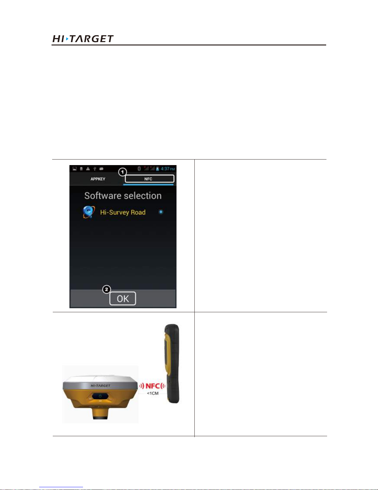
(2) Add existing coordinate system files
1. Click ① to add an existing datum
system file.
2. Select a datum system file be imported
before.
Notice:The dam file can be built with HGO post processing software or be output by User
Defined. Copy it to the “Geopath” folder, then it can be loaded by software.
Work Modes Introducation
Page 37
33
V100 GNSS RTK System Getting Started
1. Long press "APP" button on
keyboard. Press NFC; select
"Hi-Survey Road".
2. Press "OK".
3. Take ihand20 NFC response area
close to receiver's NFC response
area.
3. Device connecting
NFC (Near Field Communication)*
NFC is used to quickly establish Bluetooth connection. On condition that the handheld controller or
smart phone supports NFC function
The application of NFC, combined with new intelligent handheld, a light touch will realize
automatically connecting to receiver and run the software through Bluetooth. Compared to the past
complicated connection process, V100 GNSS receiver is more convenient and efficient.
Page 38
34
Work Modes Introducation
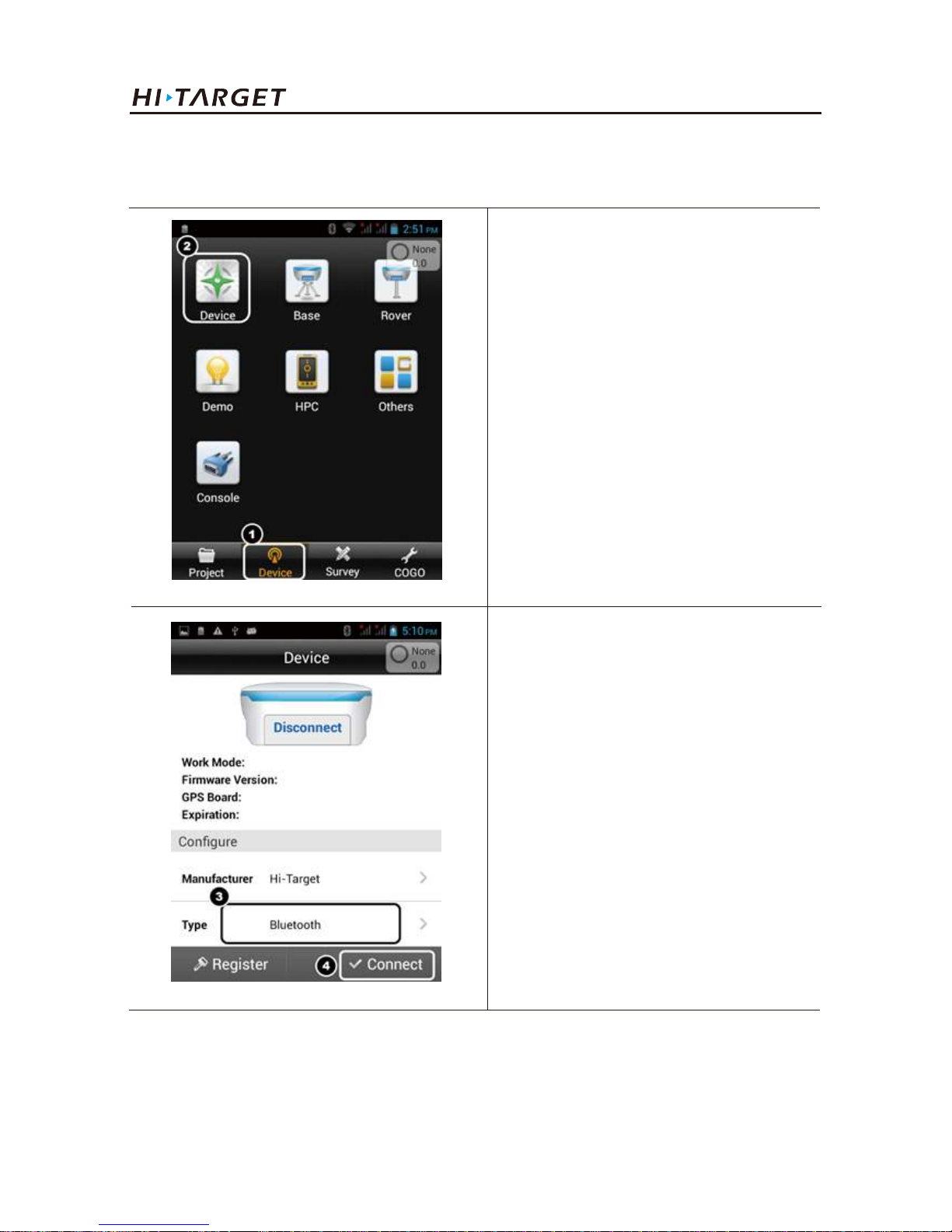
1. Slip to Device tab.
2. Press Device.
3. Select Bluetooth.
4. Press Connect.
Bluetooth connection
The receiver can also be connected by Bluetooth manually.
Page 39
35
V100 GNSS RTK System Getting Started
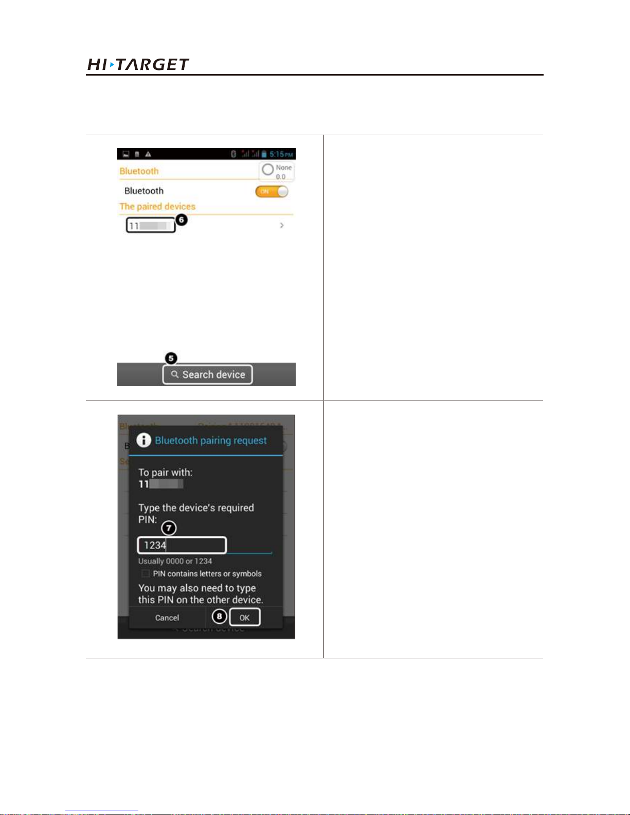
5. Search device.
6. Or select the receiver from the list
directly.
7. When connect to a new receiver,
PIN is needed.
8. Enter 1234,press OK.
Page 40
36
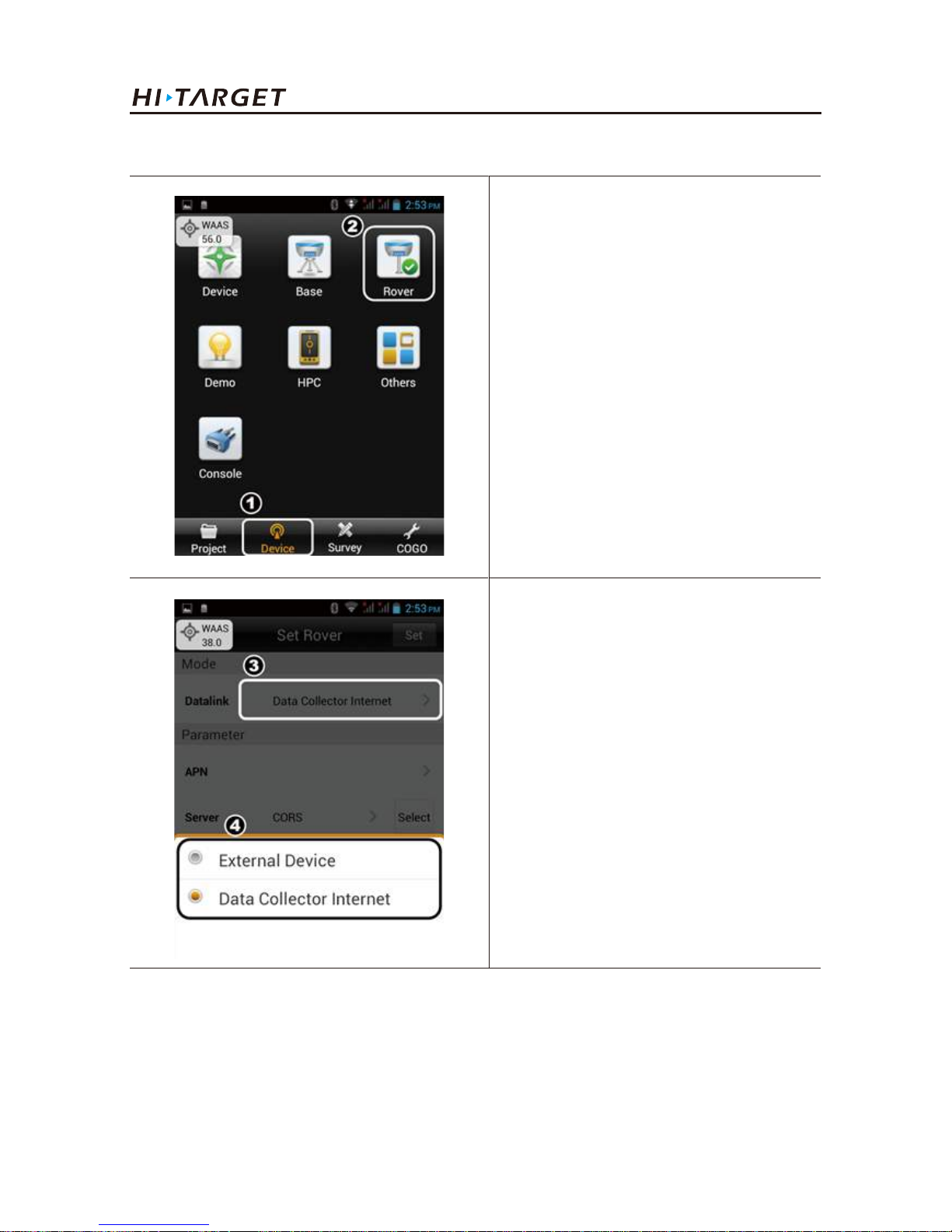
1. Slip to Device tab.
2. Press Rover.
3. Press ③ to set Data-link.
4. Select Data Collector Internet
mode.
Work Modes Introducation
4. Rover setting
Page 41
37
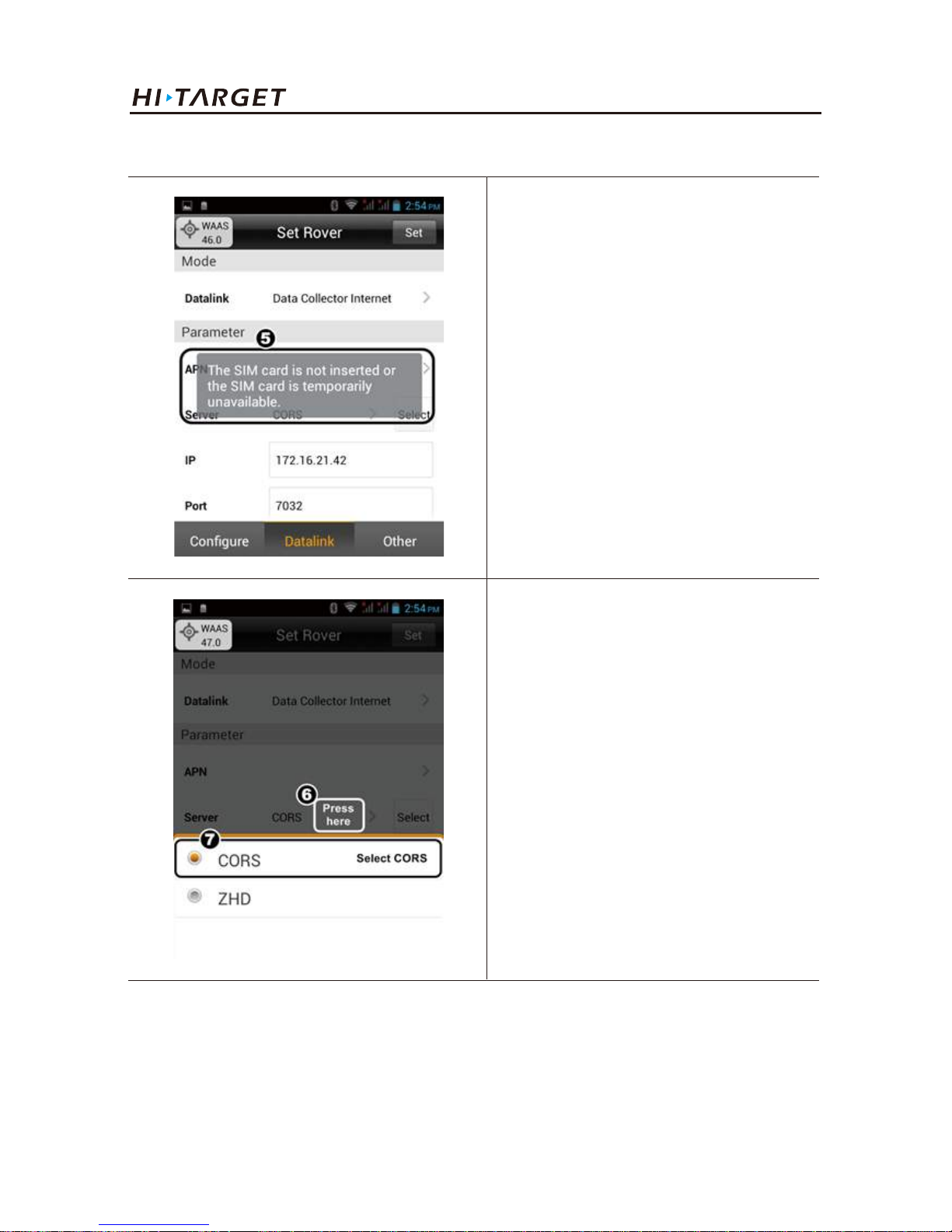
5. Make sure your controller has SIM
cards installed.
Select the right APN option.
6. Press ⑥ to select communication
mode.
7. Select CORS.
V100 GNSS RTK System Getting Started
Page 42
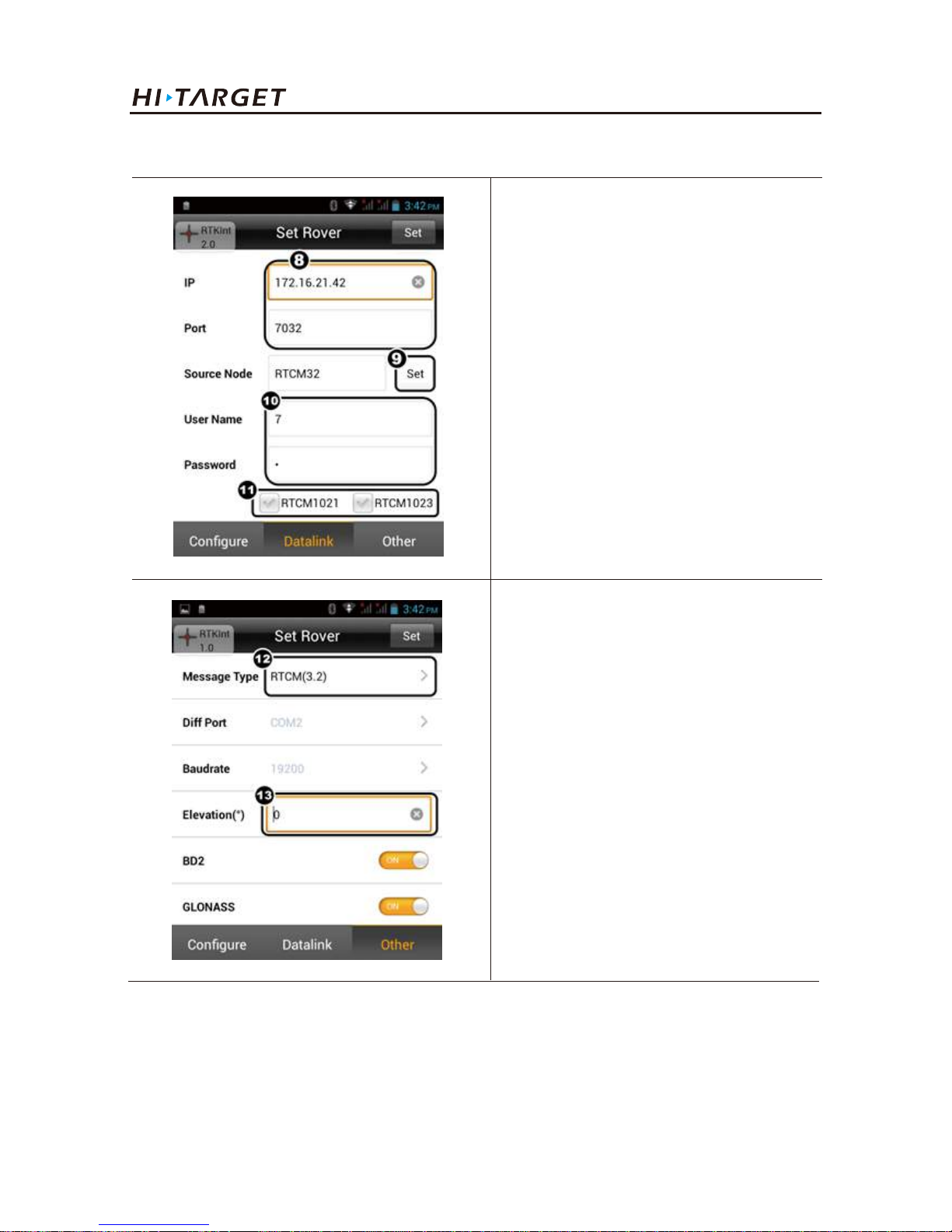
38
8. Enter the IP &Port value got from
the CORS operator.
9. Press Set to get and select
mount-points (nodes).
10. Enter the username & password.
11. Tick RTCM1021/RTCM1023 if
your CORS service operator provides
this type of message.
12. Select the Message Type same as
the node you selected.
13. Set the needed Elevation.
Press Set to finish setting.
Work Modes Introducation
Page 43
39
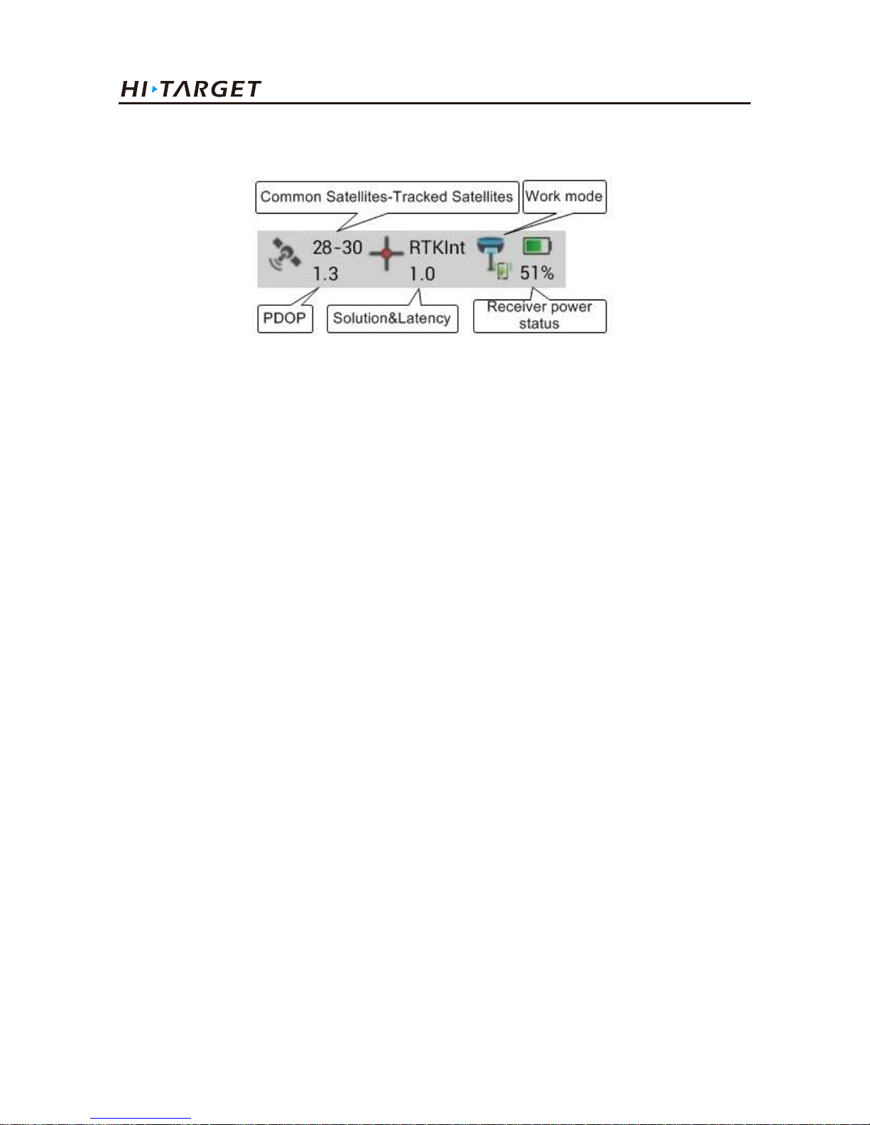
Figure 3-5
"Solution state":
It is mainly divided into the following several modes (except for fixed coordinate, precision is
arranged from high level to low level):The given point refers to fixed coordinate (Base) → RTK
fixed solution → RTK float solution → RTD solution → single point positioning →no solution
type(indicates: no GNSS data)
5. Floating box
"Correction latency":
Refers to calculating time after Rover receives the signal from Base.
"PDOP value":
Intensity factor of space geometry where the satellite is distributed. Generally, the better the satellite
distribution is, the smaller the PDOP value is. Generally, the value is less than 3 as the more ideal
state.
"Number of visible satellites":
Number of satellite received by receiver, at least 5 satellites required by RTK work.
"Number of public satellites":
Base hasn’t it and only Rover has it after receiving the difference data. It refers to the satellite used
for calculation when the Base and Rover participate in the searching of ambiguity of whole cycles at
the same time, which are generally more than 5 so as to ensure normal work.
V100 GNSS RTK System Getting Started
Page 44
40
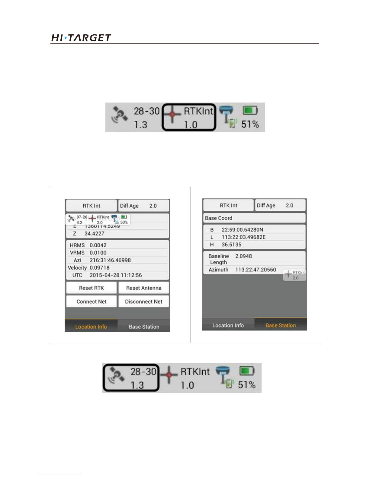
Figure 3-7
Figure 3-6
Click the satellite icon in the floating window to rapidly check detailed information of current
connected receiver satellite.
Press here to display position information of current point, including position, speed, solution state
and time, etc...
(1) Position information
(2) Stellar map
Work Modes Introducation
Page 45
41
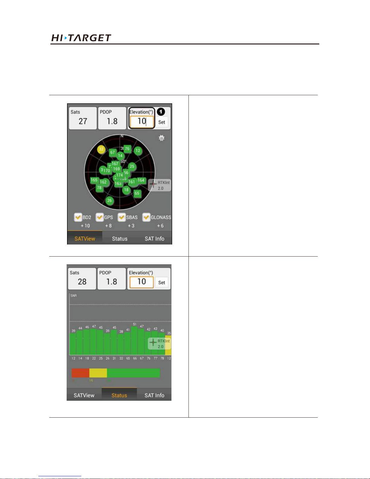
◇Distribution situation of projection position of satellite can be viewed by pressing here. Roundness
refers to GPS satellite and SBAS satellite, square refers to GLONASS and BDS satellite. GPS: Prn
value is 1-32; GLONASS: Prn value is 65-96; BDS: Prn value is 161-197.
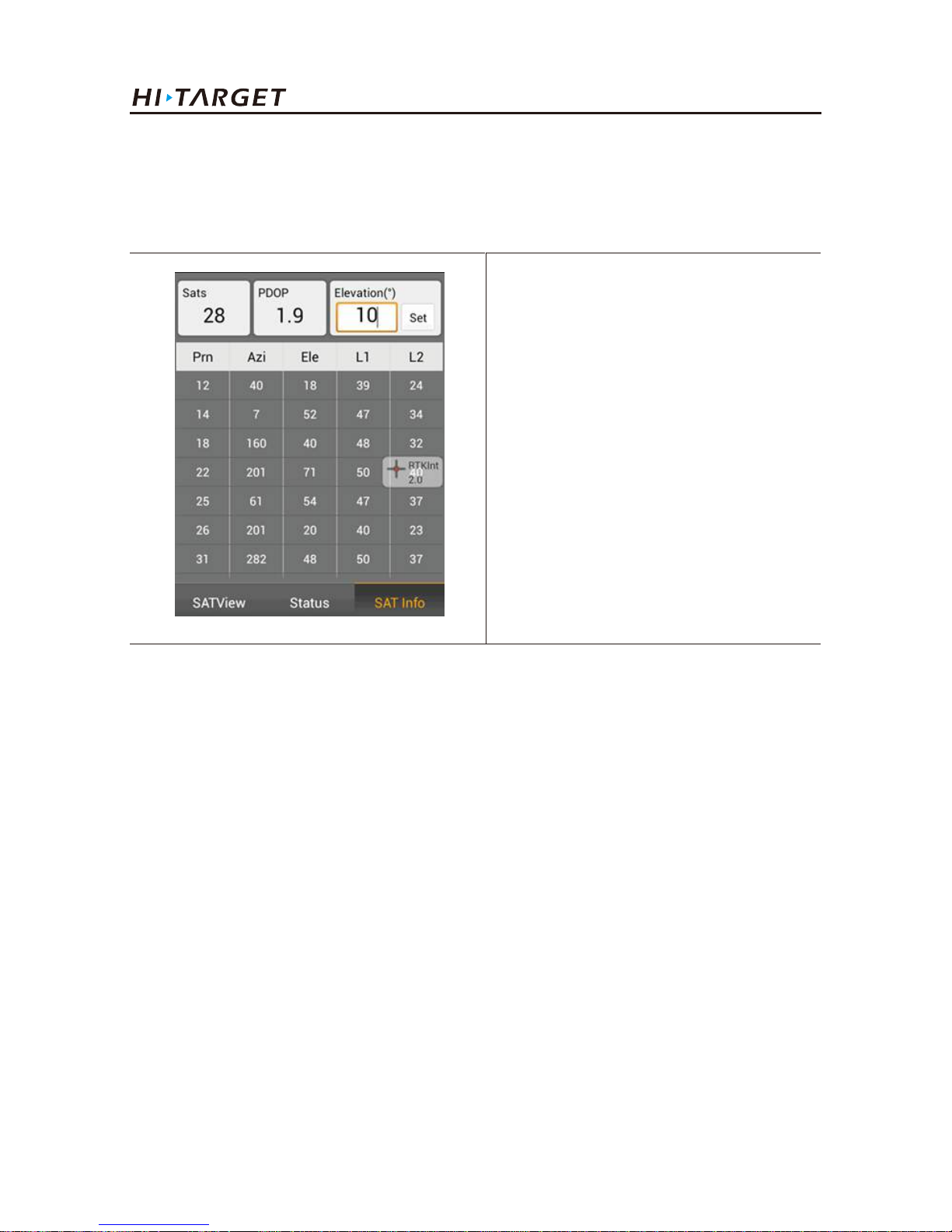
◇View elevation cut-off angle of
GNSS satellite and click "Set" to set
the elevation cutoff angle of
receiving satellite.
◇Click "Status", and give the color
according to L1 carrier signal to
noise ratio of satellite: Orange<=15,
yellow<=35, green>35As shown in
the following figure.
V100 GNSS RTK System Getting Started
Page 46
42
(3) Signal-to-noise ratio figure of satellite:
Prn refers to number of satellite; Azi refers to azimuth angle of satellite; Ele refers to satellite
elevation, L1 refers to signal to noise ratio of L1, and L2 refers to signal to noise ratio of L2.
◇Click "SAT Info", and Prn refers
to number of satellite, L1 refers to
signal to noise ratio of L1, L2 refers
to signal to noise ratio of L2.
3.2.2. Data collecting
◇ Single-point mode
◇ Average mode
◇ Automatic mode
After the settings for the above project and Base as well as Rover being completed successfully,
enter into data collection interface for collection. Corresponding collection methods can be selected
according to different demands.
Work Modes Introducation
Page 47
43
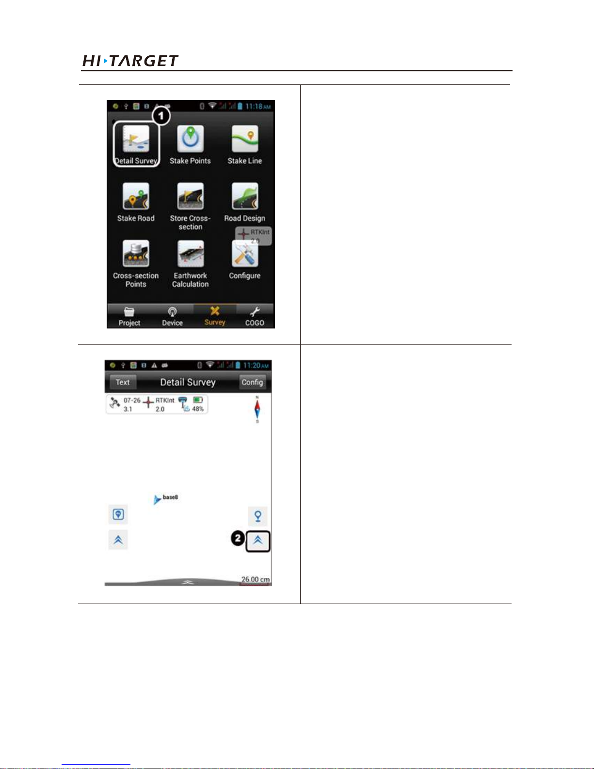
1. Slip to Survey tab.Press Detail
Survey.
1. Single-point collection
Single-point collection means collecting the data of each point by manual operation.
2. Press ② to expand the list.
V100 GNSS RTK System Getting Started
Page 48
44
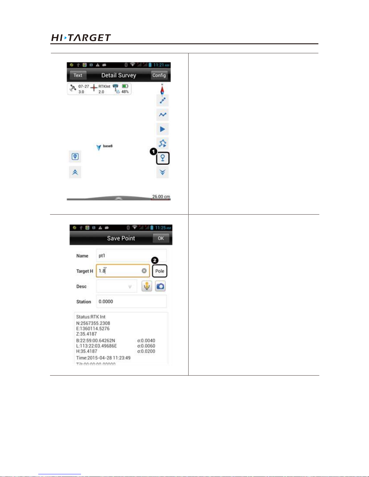
1. Press ① (or the same button on
physical keyboard) to collect.
2. Press ② to select the height type
then input the value.
The information of point, including point name, target height (the first point needs to be measured
and this value will be set as the default to the next points) and point position description (non-input
optional).Click "OK" to complete the collection of the point.
Work Modes Introducation
Page 49
45
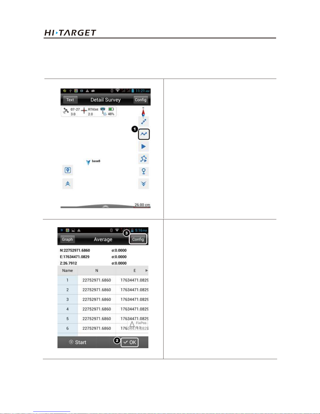
1. Press ① to collect.
2. Average collection
That is averaging for the multi-measurement value of coordinate for each point.
2. Press OK to save the point.
3. Press here to change the configuration.
V100 GNSS RTK System Getting Started
Page 50
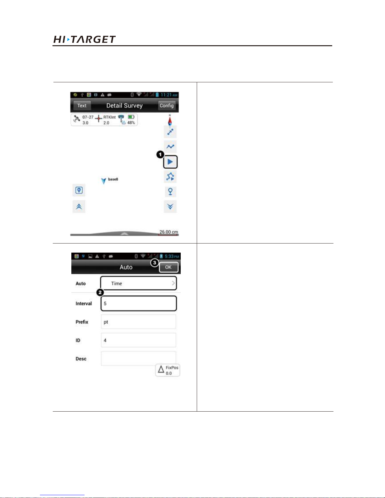
46
1. Press ① to start automatic
collection.
3. Automatic collection
Point measurement will be recorded automatically according to the configured record condition.
Work Modes Introducation
2. Select the mode and enter the
interval.
3. Press OK to start collecting.
Page 51
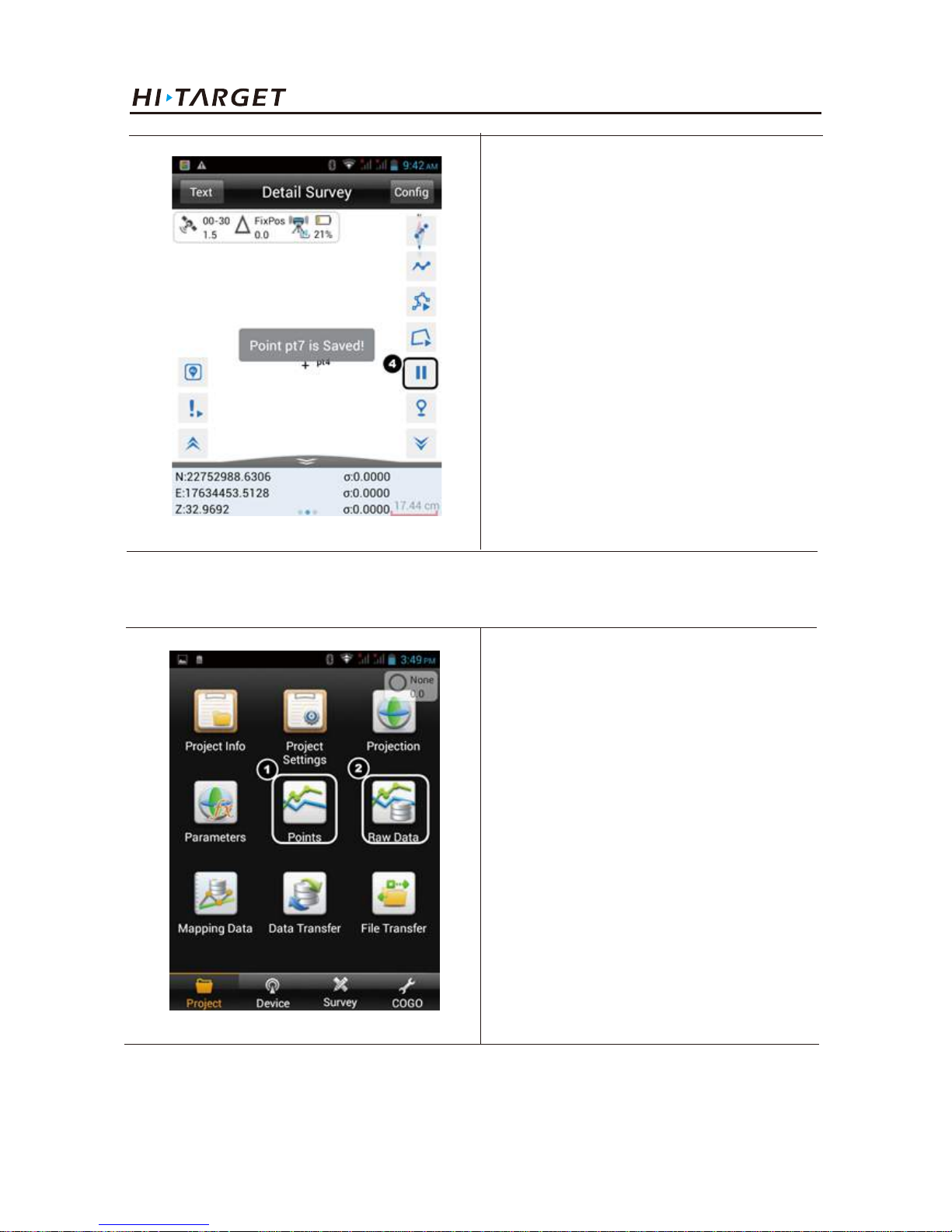
47
V100 GNSS RTK System Getting Started
4. All the points will be auto saved.
Press here to end collecting.
1. Press ① to view all collected
points.
Press ② to manage the raw data.
4. View all collected points
Page 52
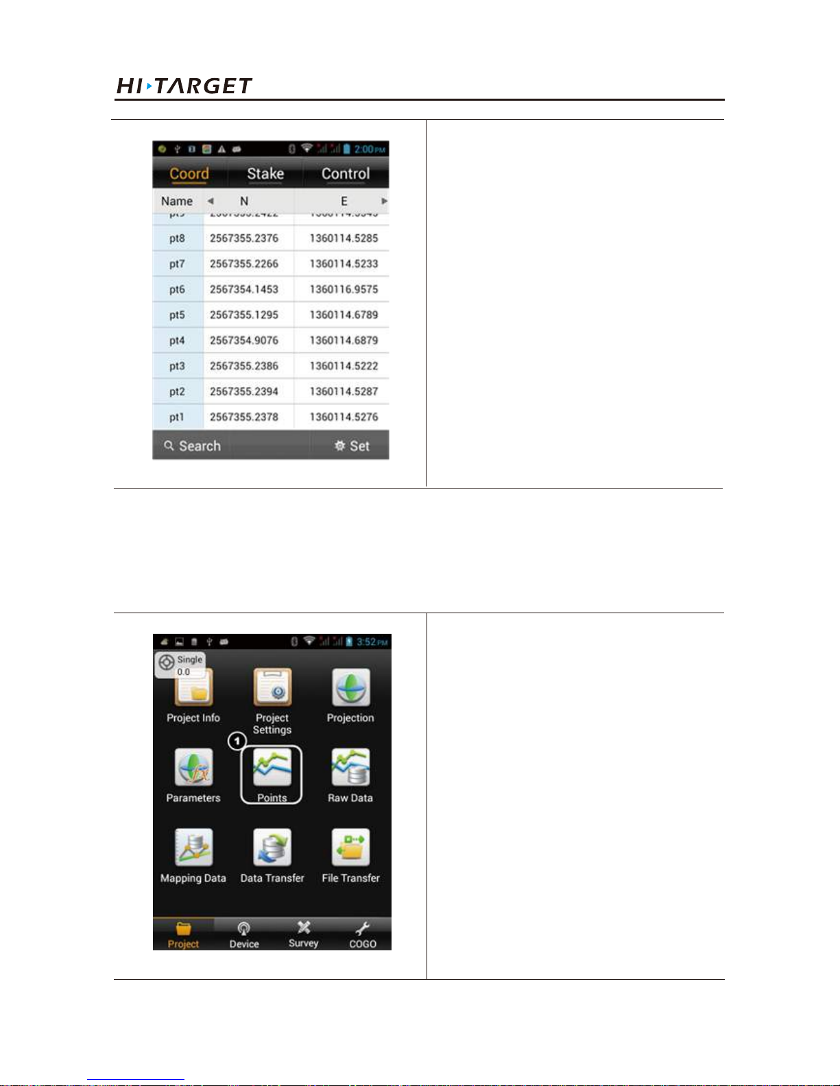
48
Work Modes Introducation
All the collected points will be
displayed in this interface.
3.2.3. Stake out
1. Import the stake point
1) Add the point manually
1. Press ① to add the point manually.
Page 53
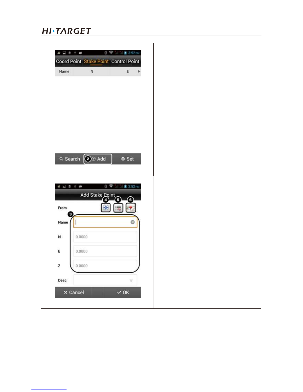
49
2) Import the points/lines from file
V100 GNSS RTK System Getting Started
2. Press ② to add point to the list.
You can add stake point by:
③Enter manually
④Get from receiver
⑤Select from list
⑥Map picking
Press OK to confirm.
Page 54
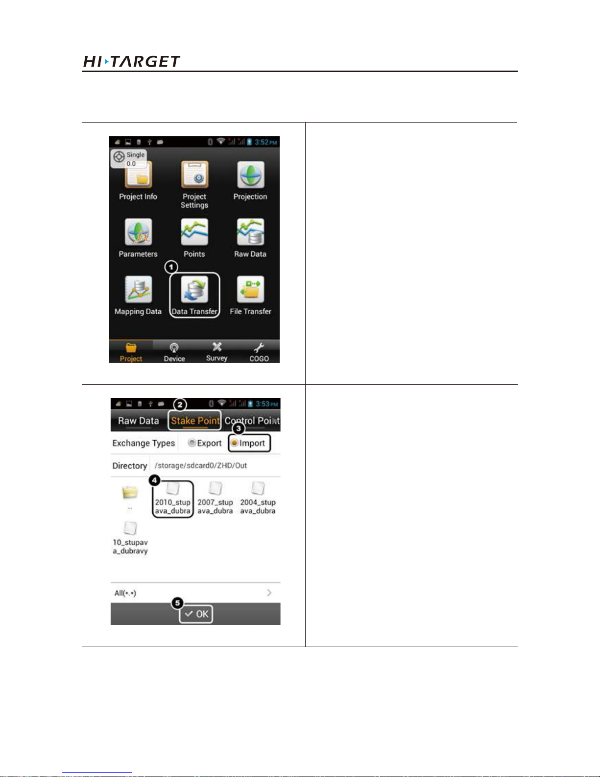
50
Work Modes Introducation
1. Press ① to import the points from
file.
2. Slip to Stake Point.
3. Select Import.
4. Choose the file you uploaded.
Page 55
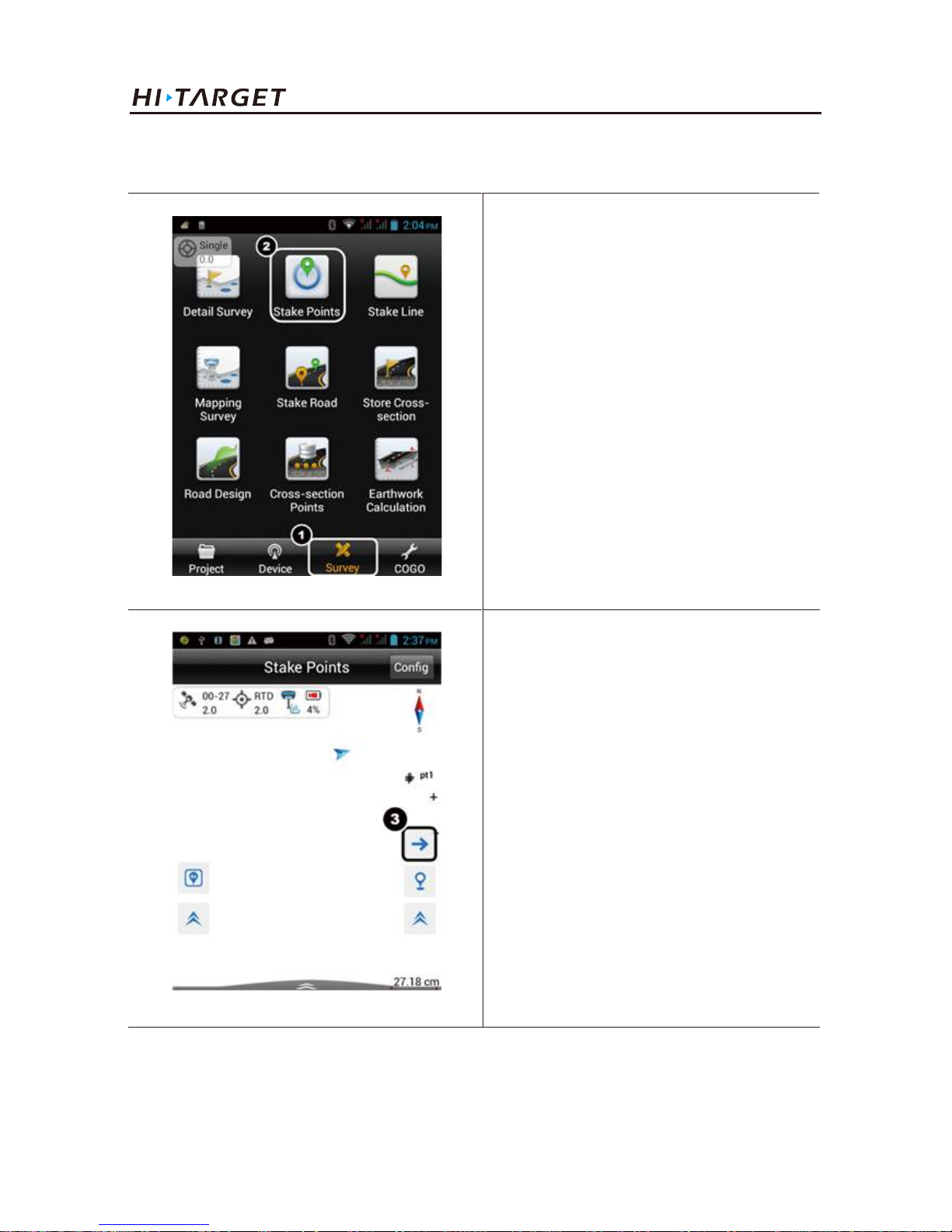
51
V100 GNSS RTK System Getting Started
2. Point Staking
1. Slip to Survey tab.
2. Press Stake Points.
3. Click here to enter into points
selection interface.
Page 56
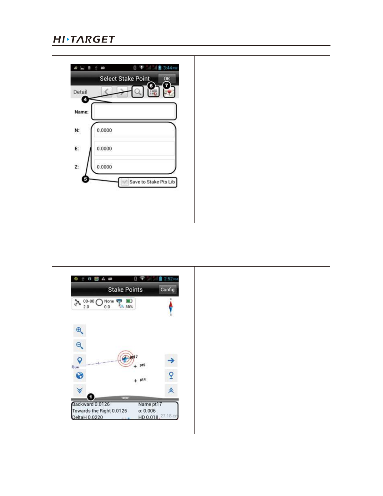
52
Work Modes Introducation
You can add stake point by:
④Enter the point name then search it
from list
⑤Input the coordinates manually
and save the point to the list by
ticking the option
⑥Select from list
⑦Map picking
Press OK to confirm and start
staking-out.
Backward: Southward
Towards the Right: Eastward
Delta H: Altitude difference between
stake coordinate and actual position
Name : Name of stake point
σ: Relative precision
HD: Horizontal Distancestaking-out
Stake interface
Page 57
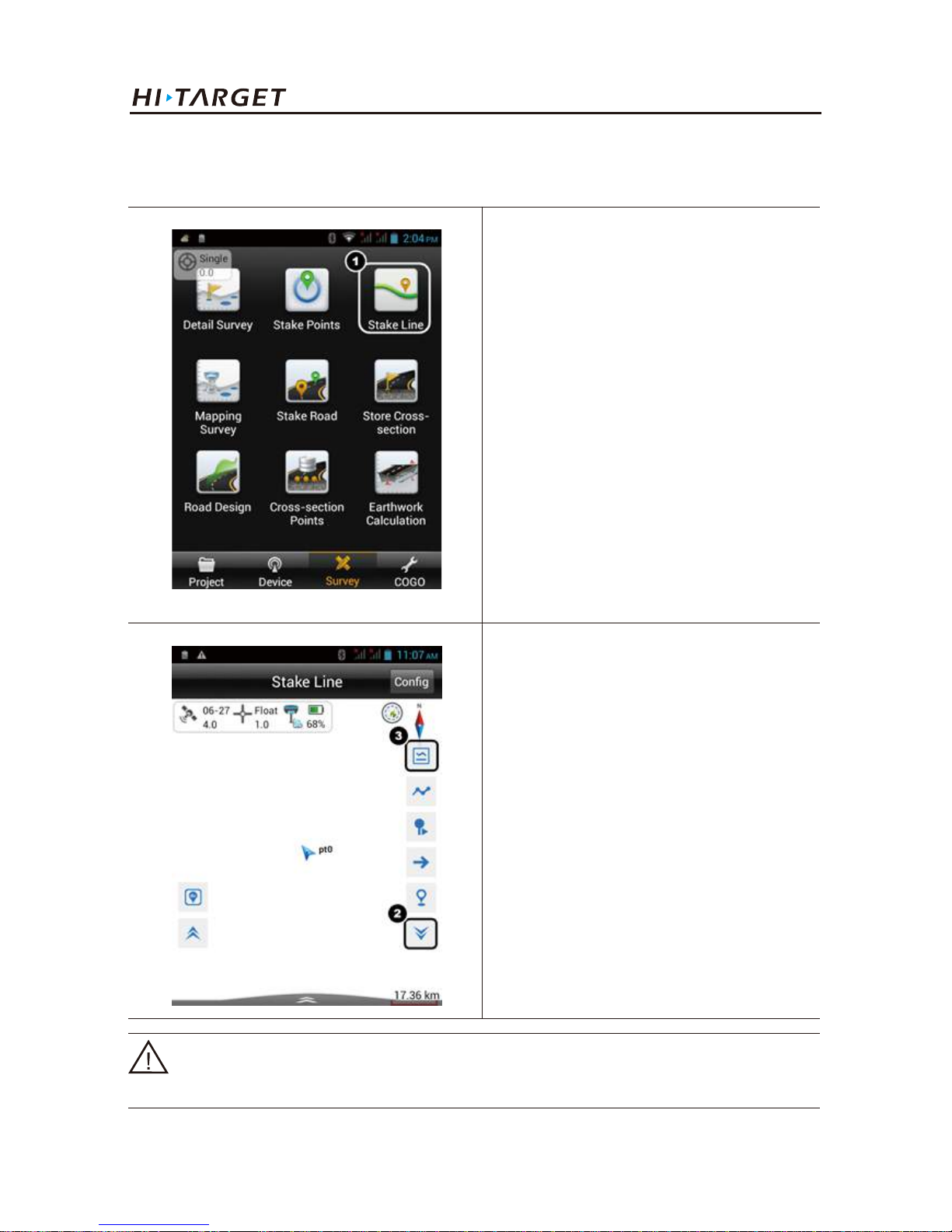
53
3. Line staking
1. Stake line from line library.
V100 GNSS RTK System Getting Started
1. Press Stake Line.
2. Press ② to expand the list.
3. Press ③ to add the line from
library.
Notice:You can define the line to be staked-out manually or import it from files. Please refer
to the manual of Hi-Survey software to get the procedures.
Page 58
54
Work Modes Introducation
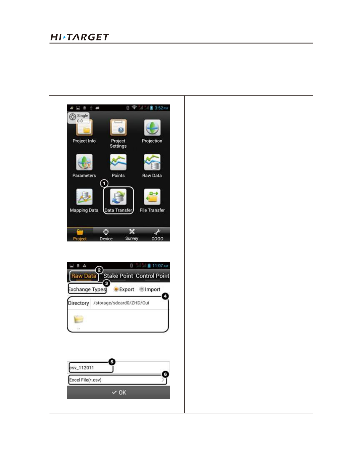
3.2.4. Data exportt
Data achievement export supports the following format: *.txt, *.CSV, *.dxf, (shp File)*.shp and
(Excel File)*.csv.
1. Press Data Transfer.
2. Press ② to select data type.
3. Press ③ to select exchange type.
4. Choose the path to output.
5. Name the file.
6. Select the format.
Press OK to confirm.
Page 59
55
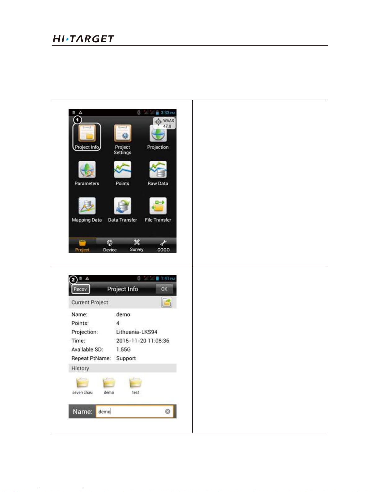
3.2.5. Auto-backup and quickly recover
Project is auto restored in Hi-Survey. External SD card is used for important data backup (Including:
Raw data, project file, coordinate system or encryption code file).
V100 GNSS RTK System Getting Started
1. Press Project Info.
2. Press ② to enter into project
recovery configuration interface.
Page 60
56
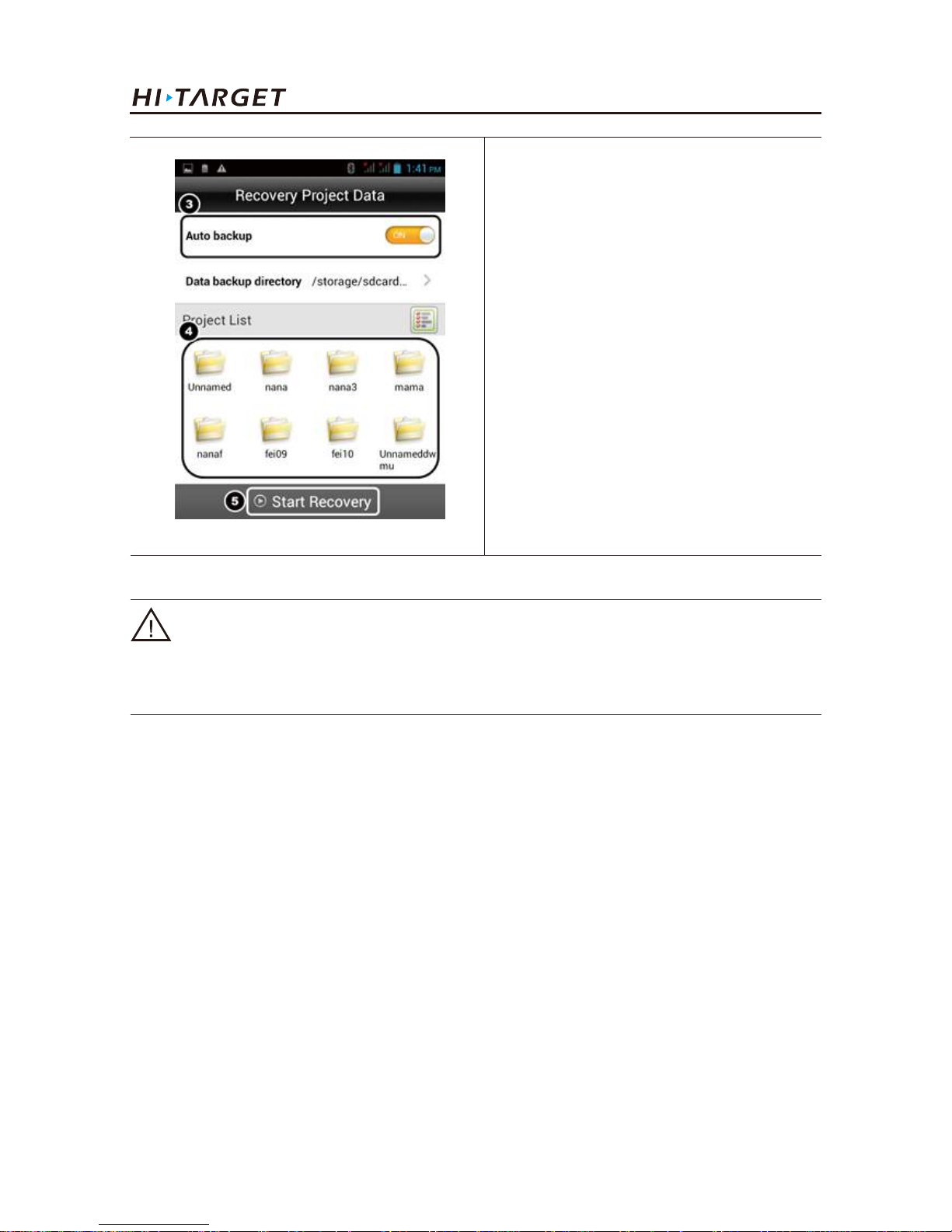
Work Modes Introducation
3. Turn on the Auto backup option.
4. Select the project to be recovered
from the list.
5. Press Start Recovery.
Notice:
The path of backup file: External SD
card /ZHD-Bak/Project/Road.
Notice:
1. External SD card is necessary for this function.
2. All the backup operations are over version 1.0.2.
Page 61
57
V100 GNSS RTK System Getting Started
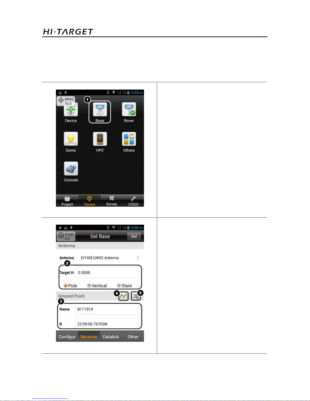
2. Select the height type and input
the Target Height.
3. Set the coordinates of base by.
③Input manually
④Smooth from receiver
⑤Select from point library
3.3. Base mode with external radio
When connected with an external radio,V100 GNSS receiver can also work as a GNSS base.
1. Connect to V100 GNSS receiver
then press Base.
Page 62
58
Work Modes Introducation
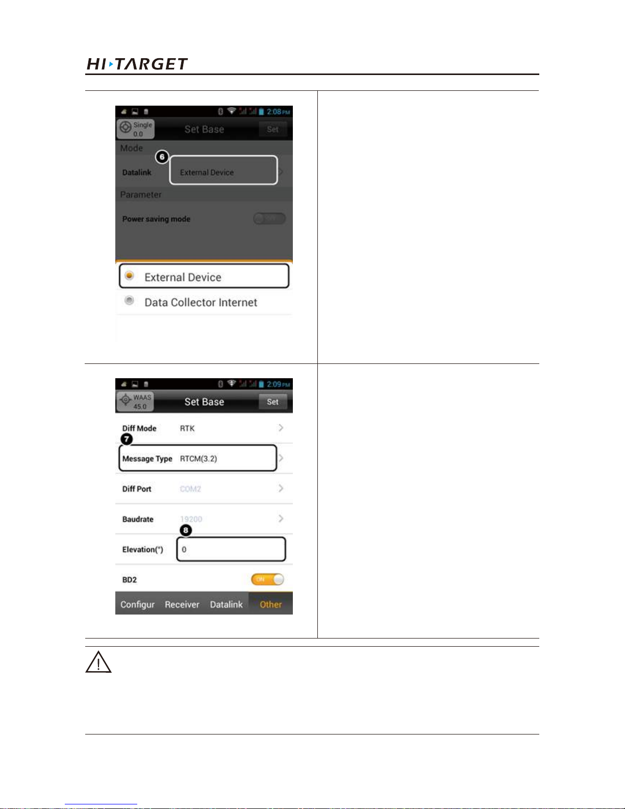
6. Set Datalink.
Select External Device.
7. Select the correction message type.
8. Set the Elevation angle.
Press Set to confirm.
Notice:
For the details of Radio which is supported and how to configure the connection, please refer to the
related documents on Hi-Target website:
www.hi-target.com.cn
Page 63

V100 GNSS RTK System Getting Started
59
C
C H A P T EER
4
Trouble Shooting
■ Registration procedure
■ Firmware upgrade
■ Reset operation
■ Schedule1 factory default parameters
■ Schedule2 key accessories information
Page 64
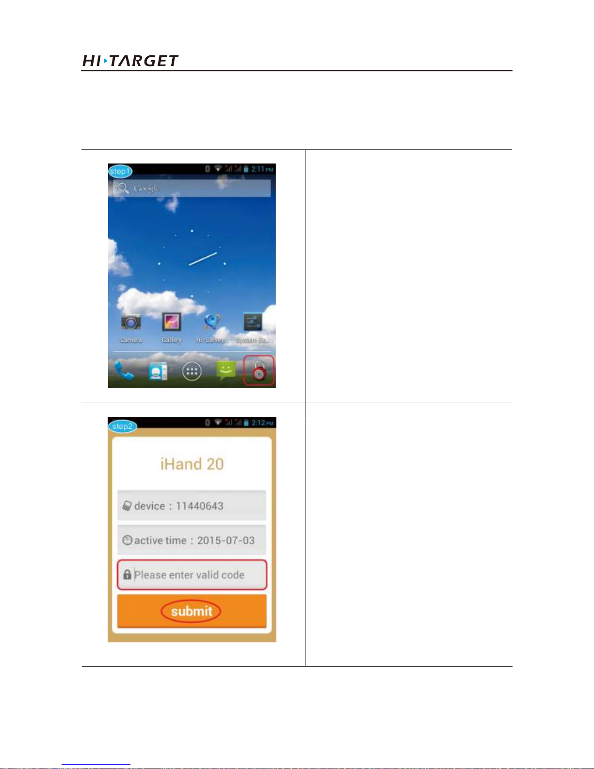
4.1. Registration procedure
Register iHand20
Figure 4-1-1
Step 1: Run the Auth Code App
which icon is like a lock. (You can
find it on the desktop or the Apps
Listing.)
Step 2: Enter the registration code in
the input box, then click submit.
Trouble Shooting
60
Page 65
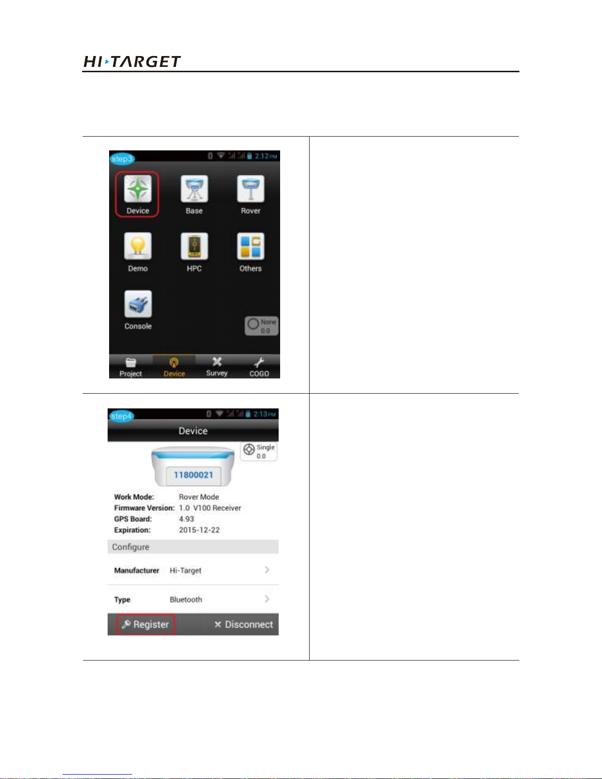
Step 3: Power on your GNSS
receiver then run the Hi-Survey App
and click the Device icon.
Step 4: Connect your GNSS receiver
first, and then click the Register icon.
Input the 24 bit registration code,
press OK.
Register GNSS receiver via Hi-Survey App
V100 GNSS RTK System Getting Started
61
Page 66
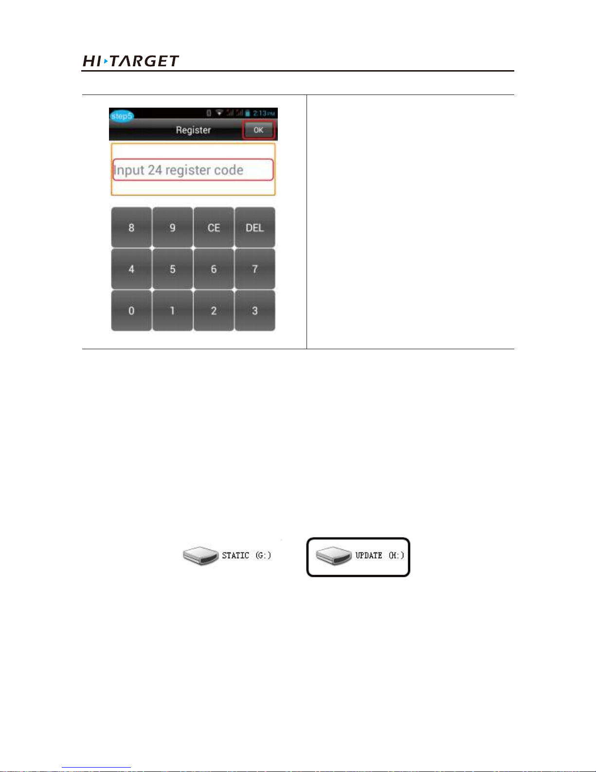
Step 5: Registration should be
successful. If failed, please check the
code and try more times.
Trouble Shooting
62
Figure 4-2-1
4.2. Firmware upgrade
The receiver can upload data like U disk , it need Mini USB data cable, one end of Mini USB data
cable is connected to computer USB port and the other end is connected to Mini USB port of
receiver. It will appear “UPDATE” disk after being connected, then open the disk, copy the firmware
files to it. Remove it and disconnect USB cable, restart GNSS receiver. The receiver will upgrade the
firmware automatically.
The new firmware can be downloaded from: www.hi-target.com.cn
Page 67

V100 GNSS RTK System Getting Started
63
4.3. Reset operation
When the Bluetooth is not connected, satellite searching fails and network connection fails, the
operation can be conducted in case that instrument restarting does not work.
Reset receiver: In power on status, long press power button (>6s) when LED begins flashing, release
power button to reset, and then restart the receiver.
Page 68
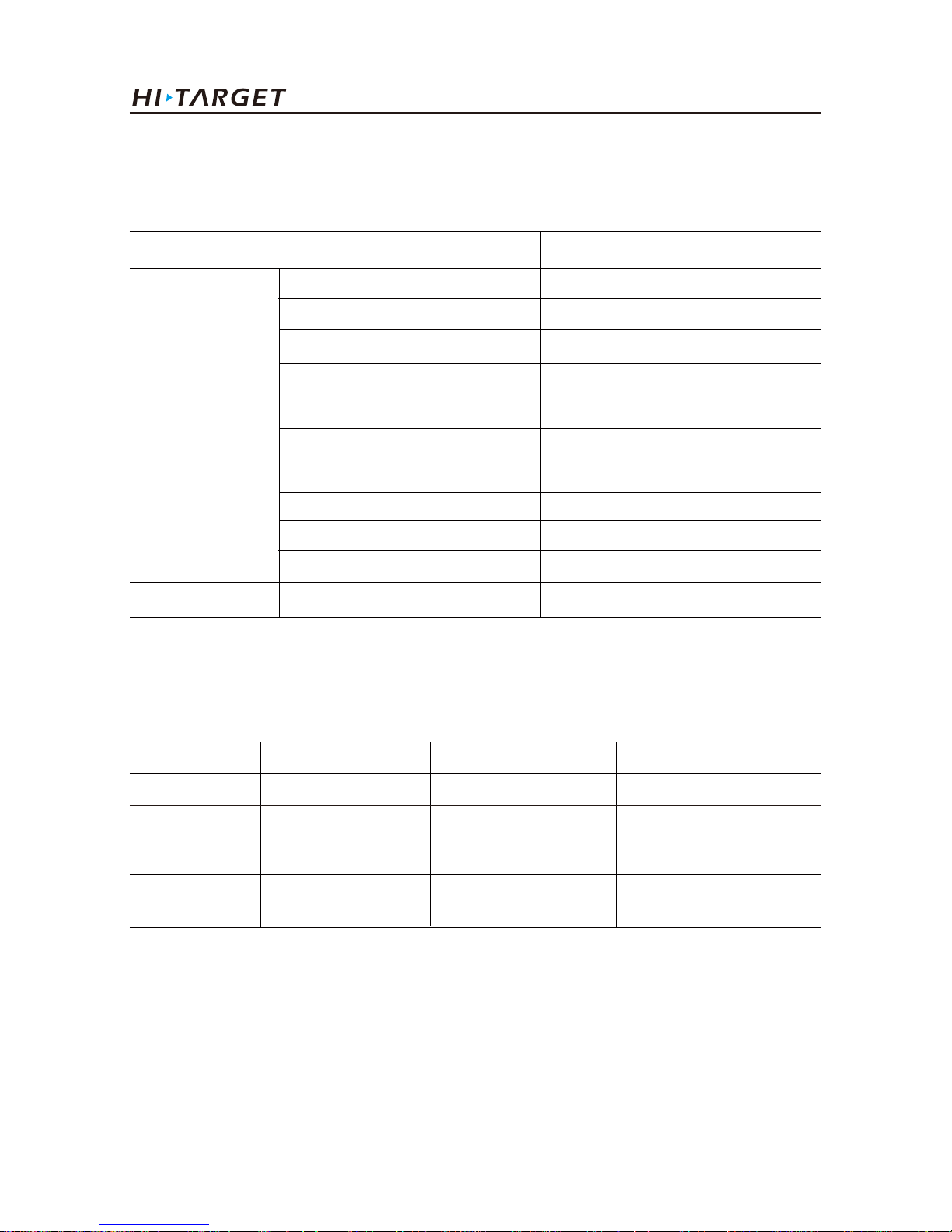
Trouble Shooting
64
Schedule2 key accessories information
Table 3 key accessories information
Name Version Manufacturer Main performance index
Motherboard BD970 Trimble 220channels
Antenna
Databoard
Small measuring
zero phase
antenna
ZHD20150010B
[PCBA]
Hi-Target Surveying
Instrument Co., Ltd
Hi-Target Surveying
Instrument Co., Ltd
51dB
Schedule1 factory default parameters
Table 2 Factory default parameters
Options content The factory default parameters
System
parameters
Working mode
Data link
Differential mode
Correction format
Elevation angle
GPS
BDS
GLONASS
Static collection interval
Static elevation angle
Rover
Data collector internet
RTK
RTCM(3.2)
10°
Enable
Enable
Enable
5s
10
Others none
 Loading...