

Hitachi Kokusai Electric SL24G US 02 User Manual
150Mbps High-speed Radio Link
Operation manual
PLEASE READ THIS MANUAL
BEFORE USING THE REPEATER

Caution:
Changes or modifications not expressly approved by Hitachi Kokusai Electric Inc.
could void the user's authority to operate the equipment.
Note:
This equipment has been tested and found to comply with the limits for a Class A digital device, pursuant to part 15
of the FCC Rules. These limits are designed to provide reasonable protection against harmful interference when
the equipment is operated in a commercial environment. This equipment generates, uses, and can radiate radio
frequency energy and, if not installed and used in accordance with the instruction manual, may cause harmful
interference to radio communications. Operation of this equipment in a residential area is likely to cause harmful
interference in which case the user will be required to correct the interference at his own expense.
Using this product close to radio or television receivers may cause receive failures. Use the
receiver correctly in accordance with the user's manual.
z Use the receiver correctly in accordance with the user's manual.
z The specifications for this product are for use in America. The product cannot be used in
other countries.
z Please be advised that Hitachi Kokusai Electric is in no way responsible for losses caused
by lost opportunities such as lost communication, or pure economic losses such as the loss
of data registered in the product, as a result of external causes such as product breakage,
malfunction, problems, or power outages. Please keep a separate record of the data
registered in this product.
z Never disassemble or modify this product.
z Use this product as a general wireless communication device. Please be advised that
Hitachi Kokusai Electric is in no way responsible for damage that occurs as a result of using
this product for applications other than a general wireless communication device.
Do not use this product for applications that require a high level of safety, such as medical
equipment or systems that directly or indirectly affect human life.
If you do use this product in applications such as devices and computer systems that
require a higher degree of reliability than a general wireless communication device,
ensure that you have thoroughly implemented adequate measures regarding failures and
safety design for the system that you are using.
z References made in this manual to the products of other companies are intended to be
references only. They are not intended to enforce use of the mentioned products.
z The contents of this manual were created with the utmost of care. However, if you are
unsure about the content, or if you find errors or omissions, please contact Hitachi Kokusai
Electric or the representative that sold you the product.
z The product manual, hardware, software, and external appearance are subject to change
without notice for the purpose of improvements. As a result, they may differ slightly from the
product that you have purchased.
z Liability for damages, based on a default on a debt or illegal activity attributed to this
product, shall be limited to the purchase price of this product or equivalent, unless Hitachi
Kokusai Electric is found to have acted in bad faith or to have been grossly negligent.
z The copyright for this manual belongs to Hitachi Kokusai Electric. Reprinting, duplicating, or
modifying all or part of this manual without permission from Hitachi Kokusai Electric is not
permitted.
z SINELINK is a trademark of Hitachi Kokusai Electric. Microsoft and Windows are registered
trademarks of Microsoft Corporation in the United States and other countries. Java Script is
a trademark or registered trademark of Oracle Corporation and its subsidiaries and partner
companies in the USA and other countries. All company names and product names
mentioned in this manual are trademarks or registered trademarks of their respective
companies. The ™, ®, and © symbols are not used in this manual.
For safe and correct operation
Before using the repeater, read this manual thoroughly to ensure proper operation.
After reading the manual, store it carefully in an easily accessible location so that it
can be referenced at any time.
About the Symbols
This manual uses a range of symbols intended to ensure the safe and correct use of
this product, and to prevent financial losses and injury to you and others. The symbols
and their meanings are explained below.
It is important to understand these symbols before reading the rest of this manual.
Warning
This symbol highlights instructions that, if ignored or handled incorrectly, may
result in death or serious injury.
Caution
Examples of Symbols
U symbol indicates information that is a warning (including dangers and warnings).
Specific warning information is provided within the symbol. The symbol on the left is an electric
shock warning.
symbol indicates prohibited actions.
Specific warning information is provided within the symbol or near the symbol. The symbol on the
left indicates that disassembly is prohibited.
symbol indicates instructions that require an action.
Specific instruction information is provided within the symbol. The symbol on the left indicates
that you must connect a grounding wire.
This symbol highlights instructions that, if ignored or handled incorrectly, may
result in injury or physical damage.
1

Please comply with the following requirements regarding PoE power
supply equipment.
Strict
compliance
Strict
compliance
Strict
compliance
z Always use IEEE802.3af-compliant PoE (Power over Ethernet) power supply equipment
(sold separately). Using other power supply equipment may cause fire, electric shock, or
equipment failure.
z Connect PoE power supply equipment to the power source specified in the user's manual
for that equipment. Connecting to other power sources may cause fire, electric shock, or
equipment failure.
z Do not exceed wiring device standards. Excess current will generate heat and may cause
fire or equipment failure.
Please comply with the following requirements regarding LAN cables.
z Always use the specified LAN cables. Power is supplied to this product through LAN cables.
Using other cables may cause fire, electric shock, or equipment failure.
z Do not scratch or damage, or forcefully bend, twist, or bundle the LAN cables, or perform
any process with the cables other than connecting the connectors. Placing heavy objects on
the cables, applying heat, or pulling the cables may damage the LAN cables and cause fire
or electric shock.
z When installing, do not squeeze the cables between the product and the wall or racks.
Doing so may damage the LAN cables or cause fire or electric shock.
z Do not install LAN cables close to a heater. Doing so may melt the cable coating or cause
fire or electric shock.
z Using a damaged LAN cable (such as a cable with exposed core or broken wires) may
cause fire or electric shock. Immediately replace a damaged cable with another LAN cable.
z When connecting or disconnecting a LAN cable, always use a connector. Pulling a LAN
cable may cause damage to the connector and cable, or cause fire or electric shock. It may
also cause the repeater or other devices connected to the LAN cable to fall or topple,
resulting in injury.
z When connecting or disconnecting a LAN cable, first disconnect the PoE power supply
equipment or turn off the power supply. Failure to do so might cause electric shock.
z When inserting the LAN cable connector, ensure that it is inserted properly. Failure to do so
might allow moisture in and cause a short or improper insulation, or fire, electric shock, or
equipment failure.
Please comply with the following requirements when installing this
repeater outdoors.
z Do not perform installation work during bad weather (such as strong winds). Wind may blow
over components and result in injury or damage. Slippery conditions from rain and snow
may cause you to fall over and sustain injuries.
z Do not install the repeater in an area in which lightning may strike. Doing so might cause
fire, electric shock, or equipment failure.
z When routing LAN cables indoors, incorporate the appropriate use of STP cables and surge
protectors (sold separately). Failure to connect such equipment might cause fire, electric
shock, or equipment failure.
z Ensure that the installation location and support poles are sufficiently strong.
z If you are installing the repeater on a balcony, consult a builder to ensure that the veranda is
strong enough. If it is not strong enough, the balcony may break, or the repeater may fall,
resulting in injury.
Warning
2

Do not touch the repeater or LAN cables while it thunders.
Prohibited
Prohibited
Prohibited
Disassem-
bly
prohibited
Strict
compliance
Discon-
necting a
LAN cable
Discon-
necting a
LAN cable
Prohibited
Strict
compliance
z Doing so might cause electric shock.
Do not perform installation work while it thunders.
z There is a risk of electric shock.
Do not touch the repeater, LAN cables, or connectors with wet hands
while current is flowing through them.
z Doing so might cause electric shock.
Do not disassemble, modify, or repair yourself.
z It is a violation of law for you to disassemble this equipment yourself.
z Disassembly or modification may cause fire, electric shock, or product failure.
z If the repeater fails, ask your representative to repair it. If you disassemble or modify the
repeater yourself, you will be required to pay for repairs even if the repeater is still under
warranty.
Install the repeater out of reach of children.
z Failure to do so might cause electric shock or injury.
If you notice smoke, noise, or an odor coming from the repeater, or if it is
abnormally hot, terminate the power supply immediately.
z Failure to do so may result in fire, electric shock, or product failure.
If water or foreign objects get inside the repeater, or if the repeater
breaks, disconnect the LAN cable immediately and terminate the power
supply.
z Failure to do so may result in fire, electric shock, or product failure.
Do not install or use the repeater in a location that might result in fire or
explosion.
z Using the repeater in a location that is exposed to dust or flammable gases, such as
propane gas or gasoline, may result in an explosion or fire. Do not install or use the repeater
in a location that might result in fire or explosion.
Install the repeater in a secure and stable location.
z Installing the repeater in an unstable rack or on an incline may cause the repeater to fall or
topple, resulting in injury.
z Ensure that the surface on which the repeater is placed, the mounting location, and the
support poles are sufficiently strong.
z When mounting the repeater on support poles, such as a BS antenna stand, take
precautions to avoid the wires becoming a tripping hazard.
z Do not locate the repeater in a location that is subject to vibration and shock. If the repeater
falls or topples, injury may result.
3

Please comply with the following requirements regarding drip-proof caps
and received power monitor terminals.
Strict
compliance
Strict
compliance
Earth
connection
Earth
connection
Strict
compliance
Strict
compliance
z Do not insert, wedge, or drop water or foreign objects into the repeater. Doing so may result
in fire, electric shock, or product failure.
z Turn the drip-proof cap until it meets firmly with the base. Failure to do so might allow
moisture in and cause a short or improper insulation, or fire, electric shock, or equipment
failure.
z When opening the lid of the received power monitor terminal, first make sure that water or
foreign objects are not going to get inside the repeater. Once you have finished directional
adjustments, firmly close the lid and tighten the bolts. If the lid is not closed properly,
moisture may be allowed in, causing a short or improper insulation, or fire, electric shock, or
equipment failure.
Periodically check that the bolts are still tight.
z If the metal mounting bracket bolts or earth terminal bolts become loose, the repeater and
grounding wire may drop or fall, causing injury.
Always install an earth connection.
z Securely attach the grounding wire to the earth terminal and be sure to connect the ground
before use. Failure to connect such equipment might cause electric shock or equipment
failure.
Ground both ends of STP cables.
z When using STP (shielded twisted pair) cables for the LAN cable, install a shielded RJ-45
connector at both ends of the STP cable and ground them appropriately through the
repeater or PoE power supply equipment. If you cannot ground the cables through the PoE
power supply equipment, peel back the STP cable coating and properly ground the cable by
connecting a grounding wire to the drain wire or aluminum foil shield. Failure to connect
such equipment might cause fire, electric shock, or equipment failure.
If you do not have advanced knowledge of installations, or if you must
install the repeater in a high or dangerous place, ask a tradesman to
perform the work.
z Installing on a roof, wall, or the outside of a high veranda puts you at risk of slipping and falling.
z Installations near electrical wires are also dangerous due to the risk of electric shock.
When using this product, follow the correct procedures in accordance
with the user's manuals for the PoE power supply equipment, PCs, and
LAN devices that you are using.
z Comply with the warnings and cautions listed in the user's manuals from each equipment
provider and use the correct procedures. Incorrect use of equipment can result in personal
injury and damage to property.
4

Please comply with the following requirements regarding installation.
Strict
compliance
Strict
compliance
Caution
Prohibited
z Do not install in a location with poor ventilation. Do not cover the equipment with cloth, or
place it on thick carpet or bedding, or in close contact with a wall or furniture, in such a way
that obstructs natural ventilation. Excess heat might cause fire or electric shock.
z Do not install in an environment that has corrosive gases. Doing so might cause device
failure.
z Do not block the air pressure adjustment hole. Doing so might cause device failure.
z Route LAN cables appropriately. Tripping over LAN cables can cause equipment to fall or
topple and may result in injury. It may also cause failure or the loss of important data in
connected equipment. Take the appropriate care when connecting and installing equipment.
z Do not leave or place heavy objects on top of the repeater. If objects fall or topple, injury
may result. If the repeater becomes deformed under heavy weight and internal components
are damaged, this may cause fire, electric shock, or equipment failure.
z Do not apply unnecessary stress to the repeater. Do not let it hang and do not hang items
from it. If it topples, injury may result.
z When installing equipment, use the provided metal mounting brackets and bolts. Using other
brackets and bolts may cause fire, electric shock, or equipment failure.
z When moving the equipment, first remove the LAN cables and check that the grounding wire
has been removed. If cables are damaged, they may cause fire or electric shock.
z When cutting and swaging LAN cables and working with them, protect your body using
protective glasses and gloves. Cable core, drain wires, and aluminum foil shield can cause
injuries.
Always use the repeater with the power supply on.
z If this repeater is installed outdoors, always use it with the power supply on to avoid internal
condensation. Only turn the power supply off if it is not going to be used for an extended period.
Be very careful not to drop the repeater or any components.
z Dropping the repeater or components may cause death or injury to those below, or damage
any objects below the installation area.
z When installing the equipment, mount and install it securely so that it does not fall under its
own weight. Failure to do so might cause injury.
z Use additional installation materials, such as mounting poles and brackets, if required to
strengthen the installation.
Turn off the power supply when performing maintenance.
z When performing maintenance, always disconnect the power supply from the PoE power
supply equipment for your safety.
Caution
5

Care Instructions
Please pay attention to the following when using the equipment.
z Do not drop or throw the equipment or expose it to shock.
z Do not keep the equipment in a damp, dusty, or hot place.
z Do not wipe the equipment with solvents such as benzine or thinners.
Doing so may remove or deteriorate the coating. If the equipment is very dirty, firmly wring out a soft cloth
dampened with water, or detergent diluted in water, and remove the dirt. Then wipe it with a dry cloth.
When using a chemically-treated dust cloth, use it according to the directions.
z Remove any snow or icicles that attach to the repeater antenna as a result of snowfall. Failure to do so
may cause deterioration in the communication properties.
Please be advised of the following points regarding wireless.
z The communication speed for wireless connections may be slower than when a LAN cable is connected.
z The wireless link speed and wireless line speed indicate the maximum speed in the wireless link. The
actual speed may vary depending on the usage environment and connected devices.
6

Blank
7

Contents
For safe and correct operation ...................................................1
1. Read First.................................................................................10
1-1 Target audience .................................................................................................................................... 10
1-2 Overview of this product ....................................................................................................................... 10
1-3 Features ............................................................................................................................................... 10
1-4 Included items .......................................................................................................................................11
1-5 Other items that you will need .............................................................................................................. 12
1-6 Required tools ...................................................................................................................................... 13
1-7 Part names and descriptions for the main unit ..................................................................................... 14
1-8 Antenna directivity ................................................................................................................................ 15
1-9 Connection configuration...................................................................................................................... 16
2. Turning Power On/Off...............................................................17
2-1 Turning power on.................................................................................................................................. 17
2-2 Turning power off.................................................................................................................................. 17
3. Installation/Connection/Setup...................................................18
3-1 Steps for installing/connecting .............................................................................................................. 18
3-2 Checking the interval of the wireless section........................................................................................ 19
3-3 Setting up from a PC ............................................................................................................................ 19
3-4 Prepare for installation.......................................................................................................................... 23
3-5 Installing ............................................................................................................................................... 26
3-6 Connecting to a LAN device ................................................................................................................. 37
3-7 Checking the wireless status ................................................................................................................ 38
4. Performing Maintenance From a Web Browser .......................39
4-1 Logging in to the web maintenance window......................................................................................... 39
4-2 Configuring basic wireless and LAN settings ....................................................................................... 40
4-3 Configuring TELNET ............................................................................................................................ 42
4-4 Configuring SNMP................................................................................................................................ 43
4-5 Configuring advanced wireless and LAN settings ................................................................................ 44
4-6 Checking the device status................................................................................................................... 46
4-7 Checking the wireless status ................................................................................................................ 47
4-8 Checking the LAN status ...................................................................................................................... 49
4-9 Displaying a log .................................................................................................................................... 50
4-10 Displaying the interference wave........................................................................................................ 50
4-11 Changing login information ................................................................................................................. 51
4-12 Setting the time................................................................................................................................... 51
4-13 Configuring SYSLOG ......................................................................................................................... 52
4-14 Managing settings .............................................................................................................................. 53
4-15 Updating firmware .............................................................................................................................. 54
4-16 Saving settings ................................................................................................................................... 55
4-17 Restarting ........................................................................................................................................... 55
4-18 Reconnecting wireless connection ..................................................................................................... 56
4-19 Changing the display language .......................................................................................................... 56
8

Contents
5. Performing Maintenance From TELNET ..................................57
5-1 How to perform operations using TELNET........................................................................................... 57
5-2 List of commands ................................................................................................................................. 59
5-3 Help ...................................................................................................................................................... 60
5-4 Device settings ..................................................................................................................................... 61
5-5 IP communication-related settings........................................................................................................ 64
5-6 Wireless-related settings ...................................................................................................................... 66
5-7 Web maintenance settings ................................................................................................................... 68
5-8 SNMP settings...................................................................................................................................... 69
5-9 Operations............................................................................................................................................ 72
5-10 Viewing............................................................................................................................................... 75
6. Performing Maintenance From SNMP Manager ......................76
6-1 Supported MIB...................................................................................................................................... 76
6-2 Standard MIB........................................................................................................................................ 80
6-3 Private MIB........................................................................................................................................... 82
6-4 Supported traps.................................................................................................................................... 86
7. Appendix...................................................................................87
7-1 Product specifications........................................................................................................................... 87
7-2 External view ........................................................................................................................................ 89
7-3 Wireless channel numbers ................................................................................................................... 90
7-4 Log details ............................................................................................................................................ 91
7-5 Abnormal operations............................................................................................................................. 93
7-6 Contact information (Customer repair desk)....................................................................................... 101
7-7 Method of disposal ............................................................................................................................. 101
7-8 Example of RJ-45 connector connection............................................................................................ 101
7-9 List of default settings......................................................................................................................... 102
9

1. Read First 1-1 Target audience
1. Read First
This manual is the user's manual that explains how to use SINELINK 24G.
To ensure proper use, please read this manual before using this product.
Target audience
1-1
The installation, maintenance, or removal of data communication systems requires qualified, experienced
engineers. This manual is designed for such engineers with a working knowledge of LAN, TCP/IP, SNMP, and
web browsers.
Overview of this product
1-2
SINELINK 24G is a 24GHz data communication system capable of a maximum throughput of 95Mbps on one
side. It uses wireless data communication lines that make it easy to build a high-speed communication system
between sites in areas where it is difficult to lay wired lines.
Features
1-3
(1) Wireless Link Speed Up to 150Mbps
1 A wireless link speed of up to 150Mbps
2 Throughput of up to 95Mbps, suitable for high capacity data distribution such as high-definition and MPEGs.
Also allows for two-way 59Mbps <-> 59Mbps communication, sufficient for multimedia image transmissions
(2) 24GHz band communication with minimal interference
1 A carrier sense function that achieves stable line quality by not using channels with interference
(3) High security
1 In addition to unique private wireless protocol, all data is scrambled
2 A pencil beam antenna that does not spread electro-magnetic waves (half value angle 3˚)
(4) Simple installation
1 Compact/light weight (approx. 29 x 29 x 7 cm, approx. 3.5 kg), built-in antenna
2 Directional adjustments can be made by sight using a simple scope
In addition, directional adjustments can be made while checking the receive level with a
commercially-available digital multimeter.
3 Device settings and open checks can be performed easily from a web browser on a PC.
4 The rainproof construction allows for outdoor installation
*1: The repeater cannot perform communication if the opposed device cannot penetrate through the
installation environment. You are responsible for carrying out installation work.
*1
10
1. Read First 1-4 Included items
1-4
Included items
Before commencing the installation, check that you have all of the included items. If anything is missing,
contact the store or representative that you purchased the equipment from.
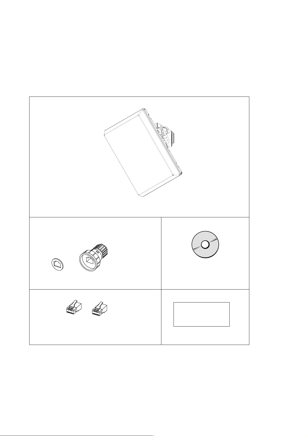
Included items
SINELINK 24G (main unit x 1)
(Approx. 29 x 29 x 7 cm, approx. 3.5kg)
The metal mounting bracket and antenna adjustment
scope have already been attached to the main unit.
Drip-proof cap (1 set)
User's manual CD-ROM (1)
Content
RJ45 Connectors (1)
(Shielded RJ-45 connectors)
Tyco Electronics AMP 5-569530-3
* Use the included shielded RJ-45 connector with the drip-proof cap.
* PoE power supply, LAN cables, and grounding wires are not included.
Electronic manual (this manual)
MIB definition file
Certificate of Warranty (1)
Certificate of warranty
11

1. Read First 1-5 Other items that you will need
1-5
Other items that you will need
Please purchase the following items as required.
LAN cable
(1) Category 5 or higher A maximum length of 100m from the switching hub to this product.
(2) A maximum diameter of φ5.0 to 6.5mm.
(3) A cable with a single-wire core.
If you are using a twisted-wire LAN cable, use the RJ-45 connector for twisted wire (sold separately).
(4) Eight core wires (four sets).
When supplying power through a signal core from a switching hub with a built-in PoE power supply
function, you can have four core wires (two pairs).
(5) When installing the equipment outdoors, use an outdoor STP cable (shielded twisted-pair cable) that
is water-proof and resistant to ultraviolet rays.
[Proven equipment]
Nippon Seisen Cable Ltd. 0.5-4P NSEDT-SO
Wire diameter: Approx. 0.5mm (24 AWG or equivalent) Number of pairs: 4P Outer coating material: polyvinyl chloride
(PVC) Standard outer diameter: Approx. 6.5mm
Min. bend radius: 50mm Temperature range during construction: -10 to +50˚C Temperature range during operation:
PoE power supply equipment
IEEE802.3af-compliant PoE (Power over Ethernet) power supply equipment. There are two types of PoE
devices. These are the PoE power supply adapter and the switching hub with a built-in PoE power
supply function.
If you are using a STP cable, ground it through a PoE power supply device. If you cannot ground the
cables through the PoE power supply equipment, peel back the STP cable coating and properly ground
the cable by connecting a grounding wire to the drain wire or aluminum foil shield.
Noise filters and uninterruptible power supply equipment
If there is a lot of noise in the power line that is connected to the PoE power supply, we recommend that
you install a noise filter or uninterruptible power supply.
Switching hub
100BASE-TX (100Mbps full duplex) supported.
Grounding wire
Use a grounding wire.
Surge protector
Use surge protectors as needed when connecting between outdoors and indoors.
PC for configuration
Use a configuration PC to set up this product and check operations. Use the specified operating system
and web browser to ensure proper use. If you use an OS or web browser other than those specified,
the system may not operate properly during display, login, and setup.
(1) OS: Microsoft Windows 7 SP1
(2) Web browser: Microsoft Internet Explorer 8.0 or higher
(3) Set the web browser to "Do not dial" and set Java
(4) Turn off the firewall for the OS and your security software.
-20 to +60˚C
Script (Allow paste operations via Java applet script, Active script, script) to "Enabled."
12

1. Read First 1-6 Required tools
1-6
Required tools
You will need the following tools to install this product. If you do not already have these tools, please purchase
them separately.
RJ45 crimping tool
Phillips head screwdriver No. 2
(or M5)
Torque wr e n ch
(for the M6 metal mounting
bracket bolts)
LAN cable qualification tester
Vinyl tape, self-adhesive tape
Binoculars
Monitor cable
(Optional items available from
Hitachi Kokusai Electric)
Product name: SL-monitor cable
Model: HP5-010601
Torque wr e n ch
(Size 3mm for M4 hexagon socket
bolts)
Digital multimeter
Recommended product
(1) Tyco Electronics AMP 2-231652-1
(2) IDEAL 30-521
Use during installation.
Use during installation.
We recommend that you use a tool with torque control.
Use to check the quality of LAN cables swaged to wires and
the RJ-45 connectors.
Poor swages cannot be detected through a conduction
check. Use a LAN cable qualification tester that is capable
of verifying the quality of a 100BASE-TX cable.
Recommended product
(1) Fluke CIQ-100
If installing outdoors, wrap the tape around the drip-proof
cap.
Use if the opposed device is a long way away and the
installation location is not visible.
Use to adjust the antenna direction when monitoring the
receive level. Use this cable to connect the received power
monitor terminal and the digital multimeter.
Use to open and close the lid of the received power monitor
terminal.
We recommend that you use a tool with torque control.
Use to adjust the antenna direction when monitoring the
receive level. DC: 0 to 3.3V Accuracy: Use a meter that
can measure at 1.5%.
13
1. Read First 1-7 Part names and descriptions for the main unit
1-7
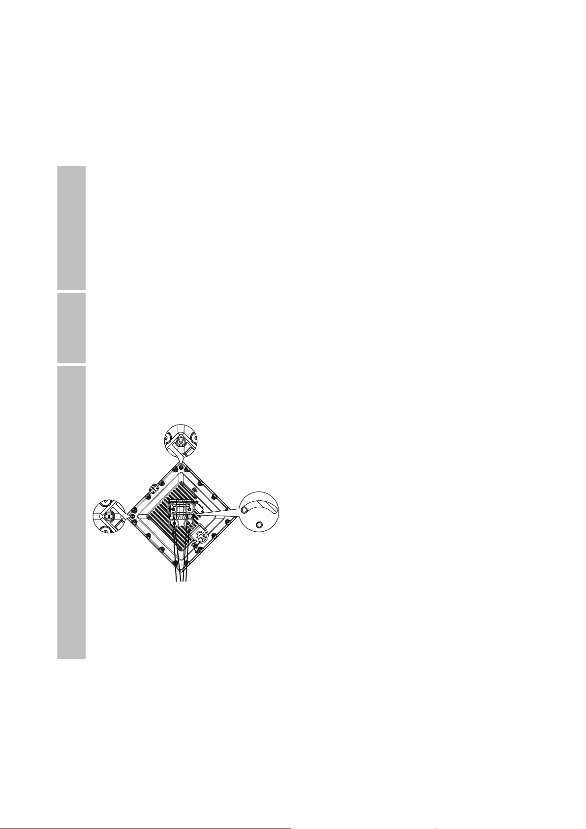
Part names and descriptions for the main unit
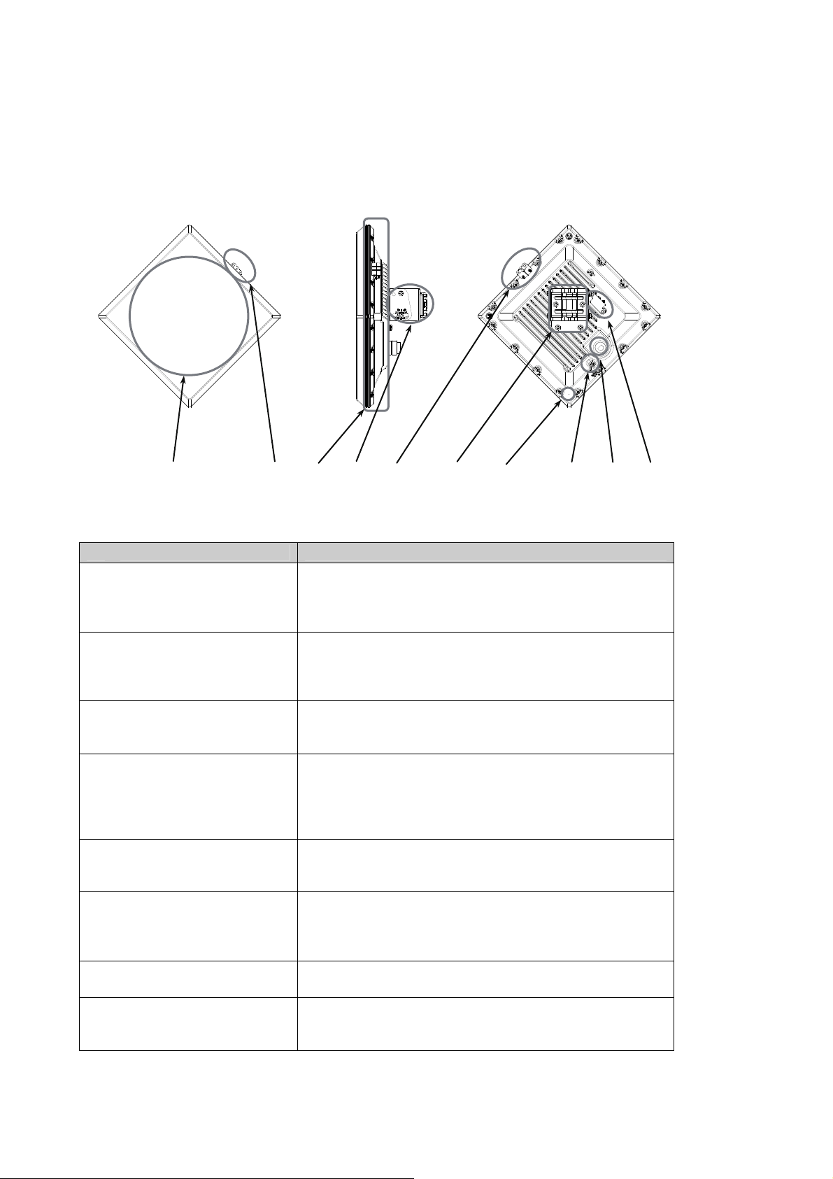
(a) (b) (c) (d) (b) (d) (e) (g) (f) (h)
Name Description
(a) Antenna Electromagnetic waves are emitted from the antenna
surface. Install the antenna facing the opposed device.
The antenna face is AES resin (water-repellent)
(b) Antenna adjustment scope Look through the scope hole to adjust the direction of this
product.
ABS resin (no coating)
(c) Radiation fin integrated
reverse-side lid
(d) Metal mounting bracket Attach this product to the mounting pole.
(e) Air pressure adjustment hole Maintain a rainproof construction and adjust the
(f) LAN cable connector Connect the LAN cable.
(g)
Earth terminal (FG) Connect the grounding wire.
(h) Received power monitor
terminal
The internal temperature escapes into the atmosphere.
Aluminum die cast (coated)
You can use a mounting pole with an outer diameter of 25
to 2.01in.
Stainless (not coated)
atmospheric pressure inside this product.
When installing the equipment outdoors, connect the
outdoors LAN cable with the drip-proof cap attached.
Connect the monitor cable.
The lid is aluminum die cast (coated)
14

1. Read First 1-8 Antenna directivity
1-8
Antenna directivity
To make communication as stable as possible when there is a opposed device, the antenna is directed within
a 0.5˚ cone to the left, right, up, and down from a line perpendicular to the surface of the antenna.
When the distance to the opposed device is 1km, 0.5˚ creates a circle with an 8.7m radius.
Antenna directivity
Horizontal direction ±0.5˚
Vertical direction ±0.5˚
Antenna pattern
0
0
-5
-10
-15
-20
-25
Gain(dB)
-30
-35
-40
-45
-50
-30 -20 -10 0 10 20 30
Angle(degree)
-1
-2
-3
-4
Gain(dB)
-5
-6
-7
-8
-2 -1 0 1 2
Most stable
communication
status
Range of half value
Angle(degree)
15
1. Read First 1-9 Connection configuration
1-9
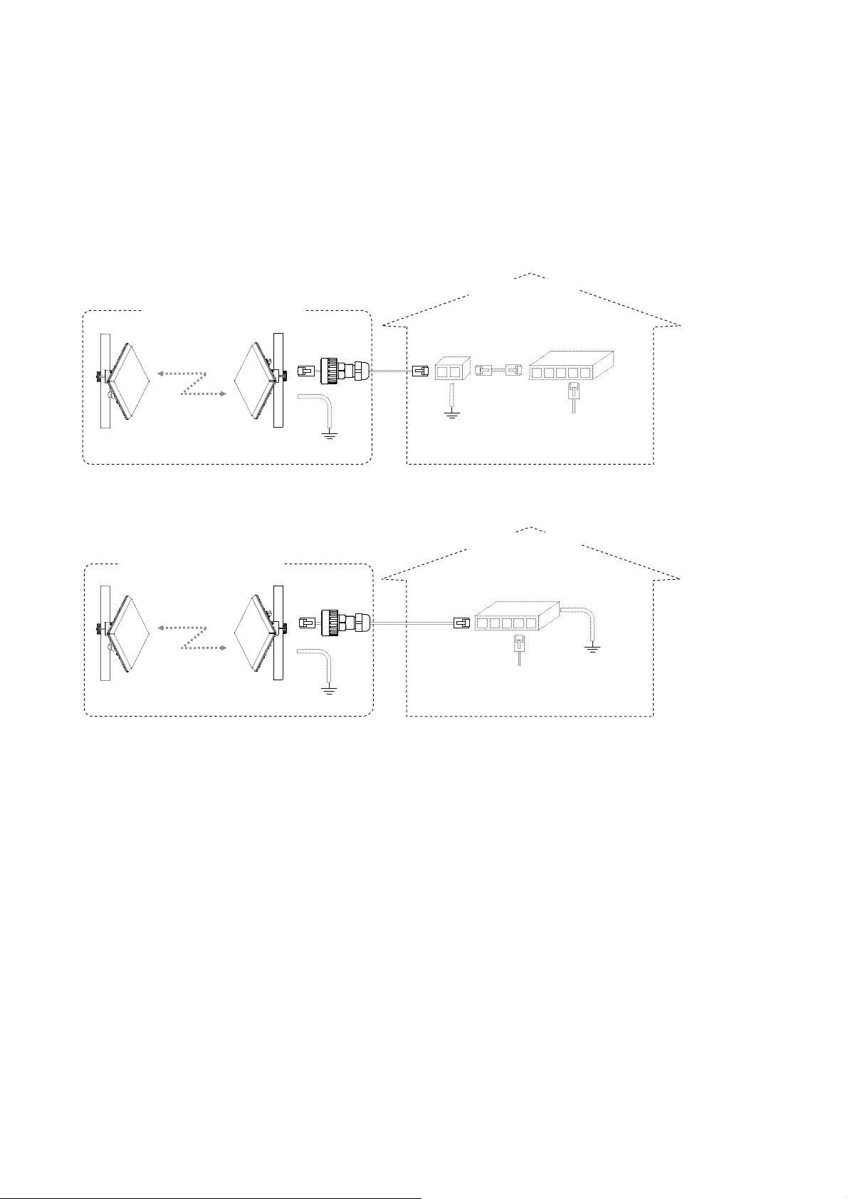
Connection configuration
The connection configuration for this product is as follows.
Connection configuration example 1
Example using a PoE power supply adapter
Indoor installation
Indoor/outdoor installation
PoE power Switching
supply adapter hub (5)
(1) (2) (3)
(6)
(4)
Earth PC for configuration,
Opposed device This device Earth connect to a LAN device
Connection configuration example 2
Example using a switching hub with built-in PoE power supply function
Indoor installation
Indoor/outdoor installation
Switching hub with built-in PoE
power supply function (5)
(1) (2)
(6)
(4)
PC for configuration
Opposed device This device Earth connect to a LAN device
(1) The minimum communication distance between the device and the opposed device is 5m.
(2) Connect the PoE power supply to this product. The total cable length for (2) and (3) is up to 100m. If you
are installing this device outdoors, use an STP cable and a surge protector (sold separately) in (2) or (3).
The length of the cable for installing outside of a building must be no more than 42m.
(3) Connect a PoE power supply adapter and a switching hub.
(4) Configure grounding for this product (earth terminal) using a grounding wire. Install the earth wire in
accordance with NFPA70 regulations.
(5) Use a switching hub that supports 100Mbps full duplex communication.
(6) Ground the STP cable in (2) through a PoE power supply device. If you cannot ground the cables
through the PoE power supply equipment, peel back the STP cable coating and properly ground the
cable by connecting a grounding wire to the drain wire or aluminum foil shield.
In addition, implement potential equalization for the grounding in (4), (6), and the surge protector.
* The connection configuration may vary depending on the conditions such as the devices that you are
using and the installation location.
* If there is a lot of noise in the power line that is connected to the PoE power supply, we recommend that
you install a noise filter or uninterruptible power supply.
16

2. Turning Power On/Off 2-1 Turning power on
2. Turning Power On/Off
Caution
Be careful of the followings when connecting or disconnecting a LAN cable.
z When connecting or disconnecting a LAN cable, first disconnect the PoE power supply equipment or turn
off the power supply. Failure to do so might cause electric shock.
Turning power on
2-1
To turn the power on, connect an IEEE802.3af-compliant PoE power supply using a LAN cable.
Check the lamp on the PoE power supply to confirm that power is being supplied to this product.
Follow the correct procedure to turn on the power for the PoE power supply, in accordance with the user's
manual that comes with each device.
Turning power off
2-2
To turn the power off, disconnect the LAN cable from the IEEE802.3af-compliant PoE power supply.
Follow the correct procedure to turn off the power for the PoE power supply, in accordance with the user's
manual that comes with each device.
To turn the power on/off, wait several seconds.
17
3. Installation/Connection/Setup 3-1 Steps for installing/connecting
3. Installation/Connection/Setup
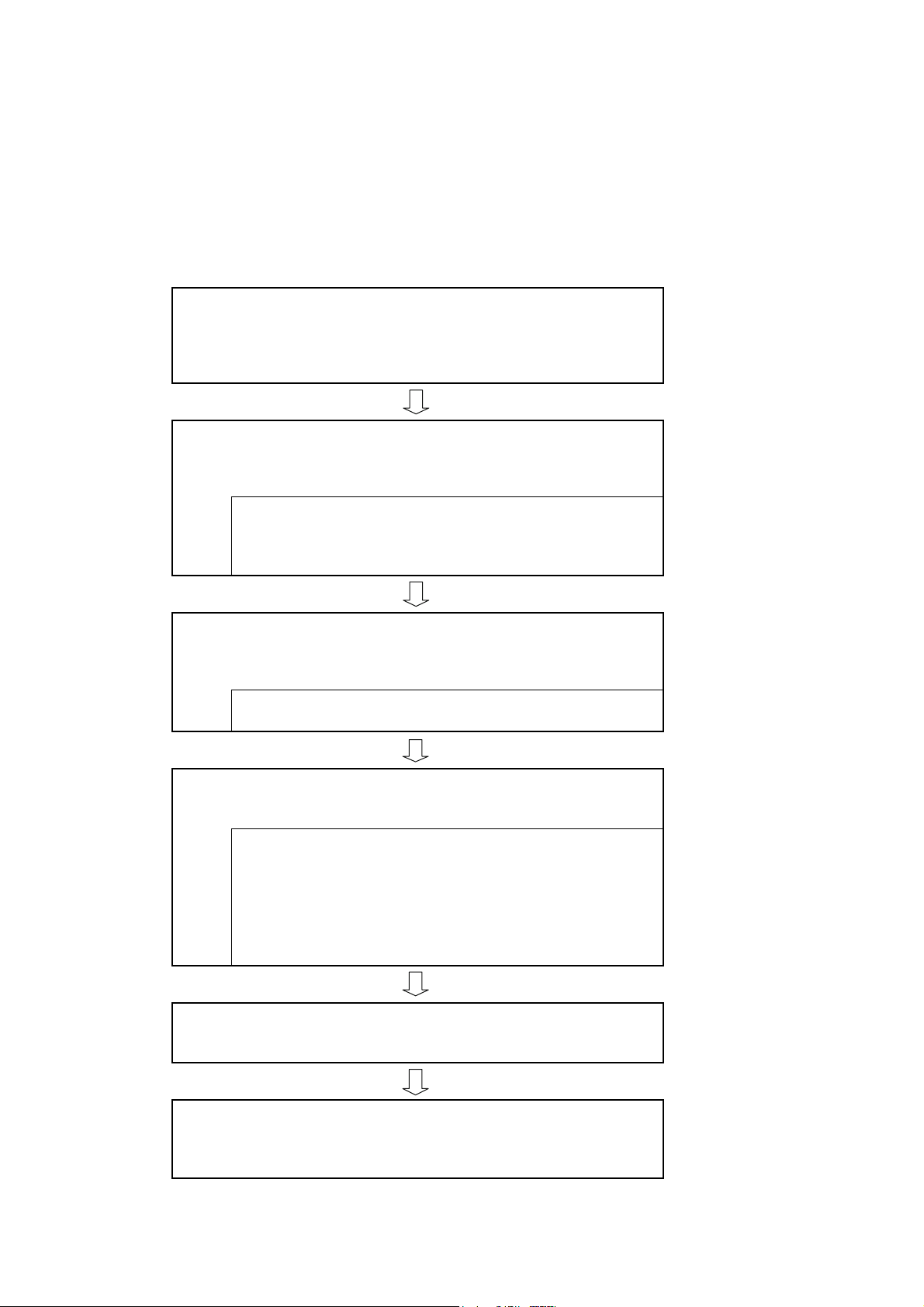
3-1 Steps for installing/connecting
This section explains the steps from installing this product to connecting with LAN devices.
Check the interval of the wireless section
adequate based on the annual rate of operation that is
Check whether the interval of the wireless section is
expected for the wireless circuit.
Setup from a PC
Configure this product's settings using a
web browser on a PC.
(1) Prepare the settings environment
(2) Change the IP address of the configuration PC
(3) Configure this product's settings from the
configuration PC
Prepare for installation
In an indoor work area, prepare for the
installation of this product.
(1) Check the orientation of the metal mounting bracket
(2) Install the drip-proof cap on the LAN cable
Install
Mount this product on a pole or others.
(1) Install the mounting pole
(2) Wire the cables
(3) Mount this product
(4) Adjust the direction with a scope
(5) If necessary, use the monitor cable to make fine
adjustments
(6) Attach the metal mounting bracket
Connect to a LAN device
Connect this product to a LAN device.
Check the wireless status
Use a web browser on a PC to
check the wireless status for this product
18

3. Installation/Connection/Setup 3-2 Checking the interval of the wireless section
3-2
Checking the interval of the wireless section
When performing wireless communication outdoors, there is a possibility that the wireless circuit will get
disconnected as a result of attenuation from rain. The longer the interval of the wireless section, the greater
the impact from rain. Thus, the interval that you can install is limited by the annual rate of operation that you
want from the wireless circuit.
Setting up from a PC
3-3
Prepare the configuration environment and configure the settings for this product from a web browser on the
configuration PC.
(1) Prepare the settings environment
Connect the PoE power supply device, switching hub, configuration PC, and this product with LAN cables.
For information on the connection configuration and how to turn on the power, refer to "1-5 Other items that
you will need," "1-9 Connection configuration," and "2-1 Turning power on."
Check the following information to see if your PC has the appropriate environment for setting up this product.
z PoE power supply equipment
Supplying power to this product.
z LAN cables
The total cable length from this product to the switching hub is not more than 100m.
The LAN cables from this product to the switching hubs are all straight cables.
(If the switching hub supports Auto MDI/MDI-X, you can also connect using a cross cable.)
z Switching hub
100BASE-TX (100Mbps full duplex) or equivalent.
The setting for the connection port for connecting to this product is auto negotiation or 100Mbps full
duplex fixed.
This product supports auto negotiation. If connected devices do not support auto negotiation, link up
using 100Mbps full duplex.
The connection port for connecting with this product is linked up at 100Mbps full duplex.
The connection port for connecting with the configuration PC is linked up.
z PC for configuration
The connection port for connecting with the switching hub is linked up.
19
3. Installation/Connection/Setup 3-3 Setting up from a PC
(2) Change the IP address of the configuration PC
When this product is shipped, the IP address is set to 192.168.0.202 and the subnet mask is set to
255.255.255.0.
Change the IP address and subnet mask for the configuration PC to the following values.
IP address 192.168.0.1 to 192.168.0.254
(excluding 192.168.0.202)
Subnet mask 255.255.255.0
To take multiple SINELINK units with factory default settings and set them up in a series, first connect the
configuration PC to the PoE power supply device, and then connect this product unit and PoE power supply
device that you want to configure. If you connect this product to the configuration PC after you have current
flowing to the unit, the ARP tables will not be updated and you may not be able to perform maintenance work
on this product.
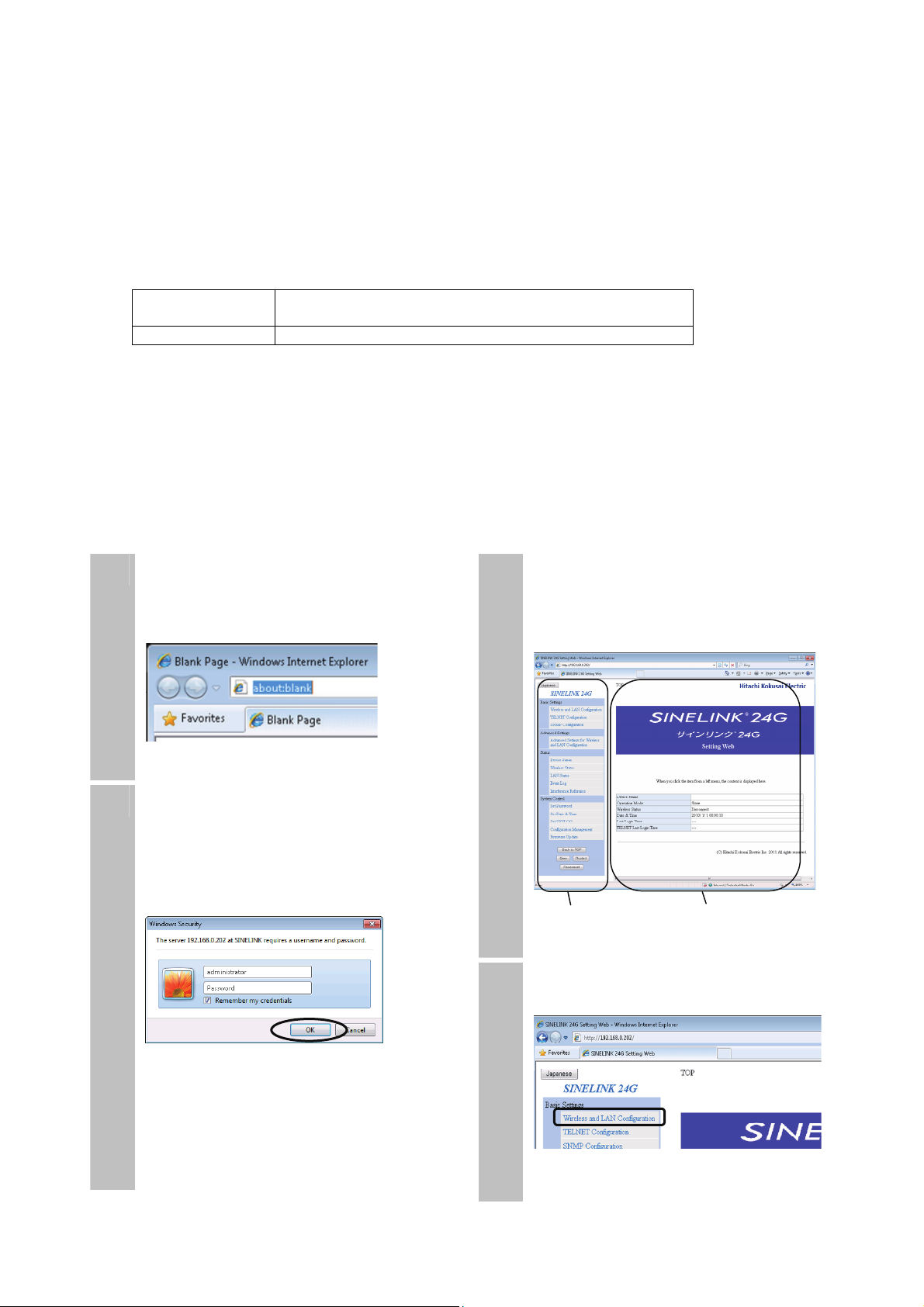
(3) Configure this product's settings from the configuration PC
Configure the settings so that the opposed device can be communicated with wirelessly through a web browser.
Configure the settings for the main device and the opposed device.
Open the web browser and enter the IP
1
address for this product in the address
bar to connect.
The default IP address is 192.168.0.202.
Enter a user name and leave the
2
password blank to connect.
The default user name is
"administrator".
A default password is not set. Make
sure that you set up a password later.
The main page is displayed.
3
In the web maintenance window, a menu
is displayed on the left side and
information is displayed on the right side.
Menu display Information display
On the menu, click "Wireless and LAN
4
Configuration".
20

3. Installation/Connection/Setup 3-3 Setting up from a PC
Enter the following settings.
5
For details, refer to "4-2 Configuring
basic wireless and LAN settings."
Device Name
Enter the name of the main unit.
Operation Mode
Enter Master (primary station) or Slave
(tributary station).
Link ID
Enter the same strings as these on the
opposed device.
Opposed
wireless
communication
Operation
Mode
Link ID
(Example)
[For preventing interference]
Set a different Link ID for each Master
and Slave pair.
To ensure security, change the default ID.
If you set the same Link ID for multiple
pairs, normal communication may not be
possible (unable to communicate, pair
combinations not acknowledged correctly,
or unstable communication).
Master Slave
ABCDEF ABCDEF
IP address Subnet mask
Default gateway
VLAN tag Priority VID
Make suitable entries for your LAN
environment into "IP Address".
If you make invalid entries, you cannot
perform maintenance communication with
this product.
Enter every setting, and then click the
6
"Apply" button.
* The entered values are samples.
Click the "Apply" button in each setup
page. If you open another page without
clicking the "Apply" button, the entered
information is not saved and will be lost.
Click "OK" to set up this product.
7
On the menu, click the "Save" button.
8
The current settings information is saved
to the internal flash memory.
The settings remain in the flash memory
even after the power is turned off.
21
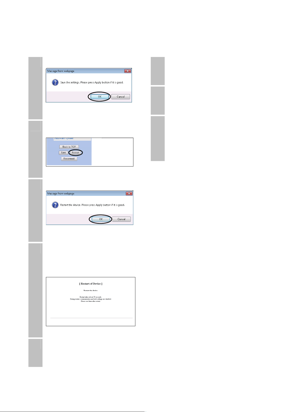
3. Installation/Connection/Setup 3-3 Setting up from a PC
9
10
11
Click "OK" to save the settings information.
On the menu, click the "Restart" button.
Click "OK" to restart this product.
14
15
16
After restarting this product, check the
settings and remove the LAN cable from
this product.
Turn off the power supply from the PoE
power supply device and disconnect the
LAN cable.
If you are storing or shipping this product
after you have unpacked it, wrap it in a
vinyl sheet and protect the LAN cable
connector from dust and foreign particles.
Otherwise, they can cause a poor good
contact with the LAN cable.
12
13
It takes approximately 30 seconds to
restart.
After you have restarted, close the web
browser.
Change the IP address for the
configuration PC to an address that can
communicate with the IP address set in
this product.
22
3. Installation/Connection/Setup 3-4 Prepare for installation
3-4
Prepare for installation
(1) Check the orientation of the metal mounting bracket
Check the orientation of the metal mounting bracket
1
On the back of the antenna there is a "V" symbol and an "H" symbol. When the unit is shipped
from the factory, the "V" symbol is at the top.
The antenna is vertically polarized when the "V" symbol is put at the top or bottom.
If you put the "H" symbol at the top or bottom, the antenna becomes horizontally polarized.
The symbol at the top/bottom needs to be the same as the opposed device. If they are different,
they will not be able to communicate properly.
Put the H symbol at the top/bottom in the following situations.
2
If there are no open wireless channels in vertical polarization and you want to use horizontal
polarization.
SINELINK pairs have been installed side-by-side in close proximity and you are concerned
about radio wave interference.
When putting the H symbol at the top or bottom, remove the four M6 nuts for the metal mounting
3
bracket on the back of the main unit (back of the antenna). Rotate the metal mounting bracket 90˚
anti-clockwise and tighten the M6 nuts. The torque for tightening the M6 nuts is 5.59 to 6.66 [Nm]
(57 to 68 [kgfcm]).
“V”
“H”
Attach with four M6 bolts
[Items to check]
The same symbol (V or H) is at the top or bottom on the main device and the opposed device.
The M6 nuts have been tightened with a torque of 5.59 to 6.66 [Nm] (57 to 68 [kgfcm]).
23

3. Installation/Connection/Setup 3-4 Prepare for installation
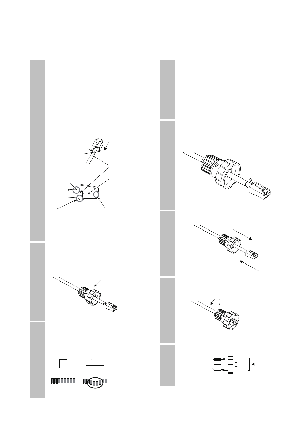
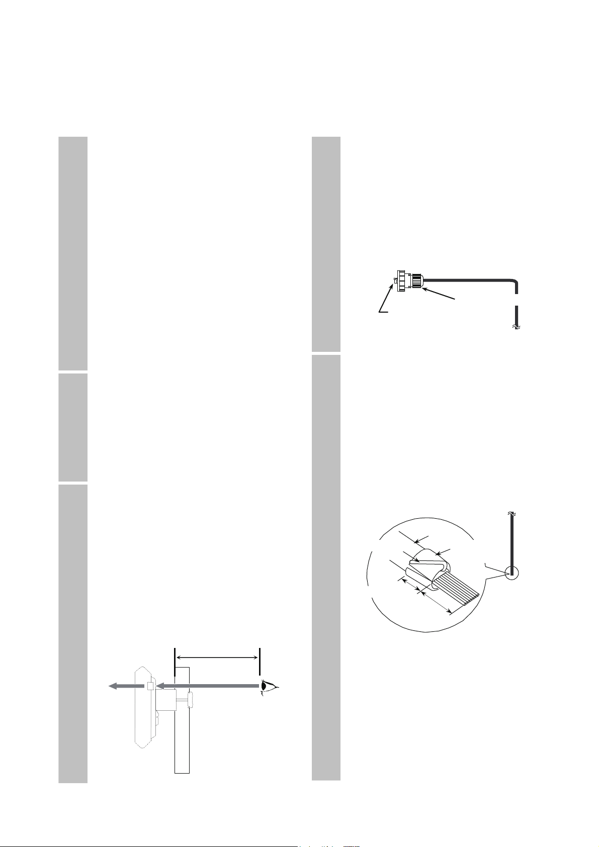
(2) Install the drip-proof cap on the LAN cable
Caution
Be careful of the following point when working with
LAN cables.
z When cutting and swaging LAN cables and working with them,
protect your body using protective glasses and gloves. Cable
core, drain wires, and aluminum foil shield can cause injuries.
Slide the cap and the base nut over the
1
cable.
Strip the coating from the LAN cable and
2
cut it off.
Be careful not to cut the aluminum foil
shield.
Coating
Aluminum foil shield
Approx.
16mm
* The construction of the cable may vary
depending on the type of cable that you
are using. Usually, aluminum foil shields,
insulating films, and drain wires are used
in STP cables but not in UTP (unshielded
twisted pair) cables.
Find the overlapping part of the aluminum
3
foil shield and separate the aluminum foil
shield from the insulating film.
Be careful not to tear the aluminum foil
shield.
Coating
Aluminum foil shield
Drain wire
Insulating film
Fold the aluminum foil shield back over
4
the coating.
Wrap it so that it is smooth around the
coating.
Coating
Aluminum foil shield
Drain wire
Insulating film
Cut the aluminum foil shield so that it is
5
even.
Firmly bend the drain wire back from the
cable to the aluminum foil shield so that it
lays diagonally across the foil. Cut it to the
same length as the aluminum foil shield.
Aluminum foil shield
Drain wire
Insulating film
Approx.
10mm
Peel back the insulating film and line the
6
core up with the RJ45 connection.
For information on lining up the core,
refer to "7-8 Example of RJ45 connector
connection”.
Coating
Drain wire Aluminum foil shield
Approx.
10mm
Approx.
15mm
24
3. Installation/Connection/Setup 3-4 Prepare for installation
Insert the cable into the shielded RJ-45
7
connector.
Push it in until the core meets the tip of
the RJ-45 connector and the coating meets
with the step inside the RJ-45 connector.
Make sure that the drain wire is in contact
with the shielded part at the top, inside of
the RJ-45 connector. If the contact with
the shielded part inside the shielded
RJ-45 connector is bad, the cable will not
be grounded.
Aluminum foil shield
Drain wire
Coating
Drain wire makes
contact Core
Push the coating Insert the entire
In until it touches core until it
the step inside reaches the end
the connector
Confirm that the step in 1 above has been
8
completed properly.
Before crimping, confirm again that the
drip-proof cap has been slid onto the cable.
Drip-proof cap
Crimp the shielded RJ-45 connector.
9
Look at the shielded RJ-45 connector
from the front and check that all of the
connector pins have been fed through to
the inside.
Not fed through
to the inside
Good Bad
10
11
12
13
If the crimp is not successful, use the
provided RJ-45 connector (Tyco
Electronics AMP shielded RJ-45
connector 5-569530-3).
If you use a different RJ-45 connector,
the connection might not be drip-proof,
resulting in damage to the LAN cable
connector for this product.
Cut the excess aluminum foil shield and
drain wire.
Cut the aluminum foil shield
Cut the drain wire
Pull the shielded RJ-45 connector into
the drip-proof cap.
Tighten the base nut.
To make the connection drip-proof,
tighten the nut until it no longer turns.
Stick on the gasket.
25
3. Installation/Connection/Setup 3-5 Installing
3-5
Installing
Once you have configured all of the settings through a web browser and completed preparations for
installation, wire the cables and mount this product on the mounting pole.
Points of caution regarding the installation location and the mounting pole
The metal mounting bracket is suitable for a mounting pole of φ25 to 51mm.
Use a mounting pole that is sufficiently strong and install it securely at the installation location. Any
movement, breaking or bending of the pole will result in unstable or terminated wireless communication.
Do not install this product in a location that cannot be penetrated by the opposed device.
Wireless communication is not possible in an environment in which the electromagnetic waves are
shielded.
Do not install this product in a location where shielding objects, such as people or other objects will pass
between it and the opposed device. Doing so will result in unstable wireless communication or
disconnections.
Do not mount this product on a mounting pole that is subject to vibration or shock. Doing so might cause
device failure. If you are installing in a location that is subject to vibration or shock, purchase a mounting
pole that has adequate vibration and shock absorption and mount this product on that mounting pole.
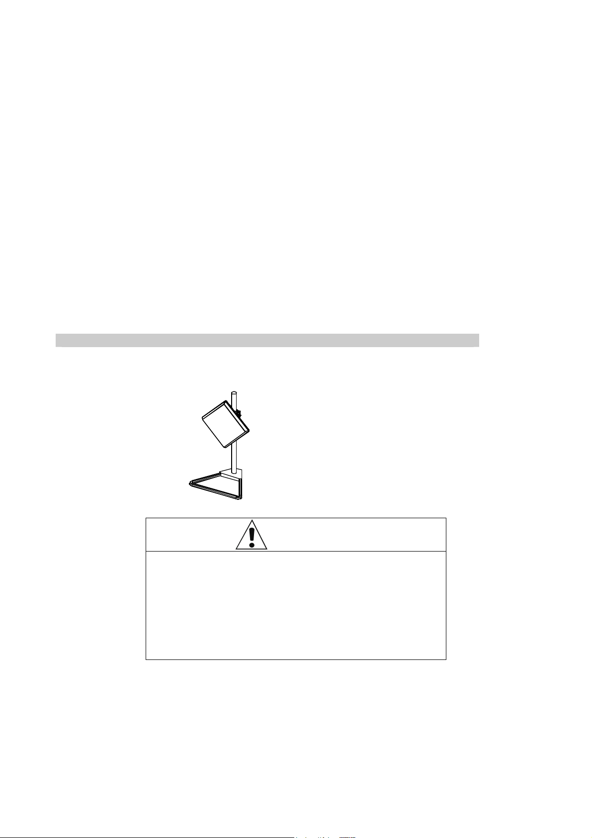
Example of indoor installation
When performing a simple indoor installation close to a window, mount this product on a mounting pole such
as a BS antenna stand.
Example of a BS antenna stand
Yagi Antenna BS stand
(BS-ST1B)
Install the stand securely so that
it does not move or fall over.
Warning
Install the repeater in a secure and stable location.
z Installing the repeater in an unstable rack or on an incline may
cause the repeater to fall or topple, resulting in injury.
z Ensure that the surface on which the repeater is placed, the
mounting location, and the support poles are sufficiently strong.
z When mounting the repeater on support poles, such as a BS
antenna stand, take precautions to avoid the wires becoming a
tripping hazard.
26
3. Installation/Connection/Setup 3-5 Installing
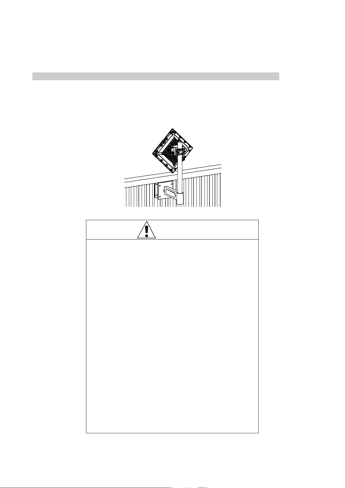
Example of outdoor installation
When installing outdoors, mount this product on the appropriate type of mounting pole, such as a
veranda/wall metal mounting bracket or roof mount.
Exam ple o f a veranda installat ion
Warning
Please be careful of the following points regarding
the installation of this product outdoors.
z Do not perform installation work during bad weather (such as
strong winds). Wind may blow over components and result in
injury or damage. Slippery conditions from rain and snow may
cause you to fall over and sustain injuries.
z Do not install the repeater in an area in which lightning may
strike. Doing so might cause fire, electric shock, or equipment
failure.
z When routing LAN cables indoors, use surge protectors (sold
separately). Failure to connect such equipment might cause
fire, electric shock, or equipment failure.
z If you are installing the repeater on a balcony, consult a builder
to ensure that the veranda is strong enough. If it is not strong
enough, the balcony may break, or the repeater may fall,
resulting in injury.
z Ensure that the installation location and support poles are
sufficiently strong.
Do not install or use the repeater in a location that
might result in fire or explosion.
z Using the repeater in a location that is exposed to dust or
flammable gases, such as propane gas or gasoline, may result
in an explosion or fire. Do not install or use the repeater in a
location that might result in fire or explosion.
27
3. Installation/Connection/Setup 3-5 Installing
(1) Install the mounting pole
Select the installation location for the
1
mounting pole.
[Items to check regarding the installation
location]
The mounting pole can be firmly
installed.
There is an unobstructed path to the
opposed device.
Screening objects, such as people or
other objects, do not pass between the
installation location and the opposed
device.
If you are using propagation off the
sea or a lake, install the pole as high
as possible.
This will reduce water surface reflection.
There are no flammable or corrosive
gases in the surrounding area.
Prepare the mounting pole that you will
2
use for installing this product.
You can use a mounting pole of φ25 to
51mm.
We recommend that you use a mounting
pole of approximately 700mm in length
for outdoor installations and 450mm in
length for indoor installations.
Install the mounting pole in a vertical
3
orientation.
Securely install the mounting pole in the
installation location and shake it to see if
it is strong enough.
Check whether there is enough space to
look through the antenna adjustment
scope. Do not install the repeater on a
pole if you are unable to look through the
scope. If you cannot see into the scope,
replace the pole with one that does allow
you to see.
22cm or more
(2) Wire the cables
Wire the LAN cable with the drip-proof
1
cap that was prepared in "3-4 Prepare for
installation", and the grounding wire, to
this product.
Wire the LAN cable and grounding wire
with enough length to reach the installation
location for this product with some length
to spare. Route the LAN cable so that
there is no tension on the cable and
connectors.
Install the shielded RJ-45 connector on
2
the LAN device end of the LAN cable.
Follow the same procedure that you used
to install the shielded RJ-45 connector on
this product end.
Refer to steps 2 to 7 in "3-4 (2) Install the
drip-proof cap on the LAN cable”.
Line the core up with the RJ45 connection.
For information on lining up the core,
refer to "7-8 Example of RJ-45 connector
connection”.
Drain wire Aluminum
Approx. 10mm
* The construction of the cable may vary
depending on the type of cable that you
are using. Usually, aluminum foil shields,
insulating films, and drain wires are used
in STP cables but not in UTP (unshielded
twisted pair) cables.
Install a shielded RJ-45 connector at
both ends of the STP cable and ground
them appropriately through this product
or PoE power supply equipment.
Drip-proof cap
This product side
Shielded RJ-45 connector
Coating
foil shield
15mm
28
 Loading...