

Hitachi Kokusai Electric KP-M1A Operation Manual
KP-M1A
B/W CCD Camera
Operation Guide
KP-M1A
Aug 2001
- 1 -

Table of contents
1. General ・・・・・・・・・・・・・・・・・・・・・・・・・・・・・・・・・・・・・・・・・・・・・・・ 3
2. Major features ・・・・・・・・・・・・・・・・・・・・・・・・・・・・・・・・・・・・・・・・・ 3
3. Specifications・・・・・・・・・・・・・・・・・・・・・・・・・・・・・・・・・・・・・・・・・・ 4
4. Name of each section・・・・・・・・・・・・・・・・・・・・・・・・・・・・・・・・・・・ 6
5. Signal connection to DC IN/SYNC connector・・・・・・・・・・・・・・・ 7
6. Arrangement of internal switches ・・・・・・・・・・・・・・・・・・・・・・・・・ 8
7. External synchronization ・・・・・・・・・・・・・・・・・・・・・・・・・・・・・・・・ 10
8. Field on demand function・・・・・・・・・・・・・・・・・・・・・・・・・・・・・・・・ 11
9. Timing chart ・・・・・・・・・・・・・・・・・・・・・・・・・・・・・・・・・・・・・・・・・・・ 18
10. Electronic shutter・・・・・・・・・・・・・・・・・・・・・・・・・・・・・・・・・・・・・・・ 24
11. Connection ・・・・・・・・・・・・・・・・・・・・・・・・・・・・・・・・・・・・・・・・・・・・ 25
12. Optical system ・・・・・・・・・・・・・・・・・・・・・・・・・・・・・・・・・・・・・・・・・ 26
13. Composition ・・・・・・・・・・・・・・・・・・・・・・・・・・・・・・・・・・・・・・・・・・・ 27
14. External view ・・・・・・・・・・・・・・・・・・・・・・・・・・・・・・・・・・・・・・・・・・ 27
15. Optional accessories・・・・・・・・・・・・・・・・・・・・・・・・・・・・・・・・・・・・ 27
16. Notes to users ・・・・・・・・・・・・・・・・・・・・・・・・・・・・・・・・・・・・・・・・・ 31
Attachment : Spectral sensitivity characteristic ・・・・・・・・・・・・ 33
KP-M1A
- 2 -

1. General
The KP-M1A is a black and white camera using the late st high grade C CD hav ing a 2/3-inc h image
size.
The KP-M1A features high se nsitivity, high resolution and high performance.
The KP-M1A is provided with various functions including the multiple step electronic shutter
function, field-on-demand function, integration mode switching function, HD/VD pulse switching
function and non-interlaced scan ni ng f unction.
The KP-M1A is most suitable for use with a microscope or an image processing system.
The KP-M1A is compatib le with the KP-M2/M3.
KP-M1AN: EIA, KP-M1AP: CCIR
2. Major features
(1)Small size and lig ht weight
Though the KP-M1A is small in size and light in weight, it offers high performance.
A video signal is obtained only by supplying 12V DC.
(2)High resolution
The latest high grade CCD is used. The horizontal resolution is 570TVL (560TVL CCIR), and
the vertical resolution is 485TVL(575TVL CCIR).
(3)Multiple-step electronic shut t er fu nct i on
The multiple-step e lectr oni c shutter function is provided.
The eight-step shutter speeds c an be selected from 1/100(1/120 for CCIR) to 1/ 10000.
(4)Internal or external synchronization, and interlaced or non-interlaced o perat ion
The synchronization system and the scanning system are automatically switched by the kind of
an external sync signal.
(5)Field-on-demand function
The image captured at an optional timing by an external trigger signal can be displayed instantly.
The capture time can be adjusted by an external trigger signal and the shutter.
(6)Frame or field integration mode
As the integration mode can be sw itched, the image ac cording t o applic ations ca n be obtain ed by
combining with the scan ning system and the electronic shutter fu nct io n.
KP-M1A
- 3 -

3. Specifications
(1)
Imaging device interline CCD
No. of total pixels EIA :811(H) ×508(V)
CCIR:795(H)×596(V)
Pixel size EIA :11.64(H)×13.5(V)µm
CCIR:11.6(H)×11.2(V)µm
No. of effective pixels EIA :768(H)×494(V)
CCIR:752(H)×582(V)
(2)
Sensing area EIA :8.94 ×6.67mm(2/3 inch size)
CCIR:8.72 ×6.52mm(2/3 inch size)
(3)
TV format EIA/CCIR
(4)
Lens mount C-mount
(5)
Flange focal dista nce 17.526mm(Not adjustab le)
(6)
Hor. Scanning freq. EIA:15.734kHz CCIR:15.625kHz
(7)
V ert . Scanning freq. EIA:59.94Hz CCIR:50Hz
(8)
Sync system Internal/external (automatic switching)
(9)
Int. sync scanning syst em 2:1 interlaced
No. of Hor. lines:525(625 CCIR)
fv=2fH/525(625 CCIR)
(10)Ext. sync input HD/VD : 2 to 6Vp-p,negativ e
Input impedance : 1k
Ω
Frequency deviation : ±1%
(1 1)Video output 1.0Vp-p/75Ω, unbalanced
Video: 0.7Vp-p
Sync: 0.3Vp-p, negative
(12)
Resolution EIA : 570TVL(H)/485TVL(V)
CCIR: 560TVL(H)/575TV L(V)
(13)
Sensitivity 400Lx, f4, 3200K
(14)
Min. illumination 0.3Lx, fl.4, AGC:ON, GAMMA:ON,
W/O IR cut filter
(15) Signal-to-noise ratio 56dB
(16)
Electronic shutter 1/10000, 1/4000, 1/2000, 1/ 1000, 1/500,
1/250, 1/125, 1/120(CCIR), 1/100(EIA)sec
OFF :Normal exposure
KP-M1A
Settable from external switch.
Set to OFF at factory.
- 4 -

(17)
Integration mode Field or frame
(Settable by external switch.)
Set to frame integration mo de at factory.
(18)
Gamma correction Gamma = 1.0 or correction
(Settable by internal switch. )
Set to 1.0 at factory.
(19)
AGC Fixed or AGC
(Settable by internal switch. )
Set to fixed gain at factory.
(20)
Field-on-demand ON or OFF
(Settable by internal switch. )
Set to OFF at factory.
(21)
Restart・Reset ON or OFF (Option)
(Settable by chip component s)
Set to OFF at factory.
(22)
Supply voltage 12V DC ± 1V
(23)
Power consumption 220mA approx.
(24)
Ambient conditions Operating:-10 to 50℃, 90%RH or less
Storage :-20 to 60℃,70%RH or less
(25)
Anti-vibration 98 m/s
2
(10 to 60Hz,amplitu de:0.98mm constant
60 to 200Hz amplitude, variable)
(10 to 200Hz, sweep:1 min, XY Z, durat i on:30mm.)
(26)
Anti-vibration 686 m/s
2
(Once each, top/bottom/lef t side/right side)
(27)
Dimensions 44(W)×29(H)×72(D)mm
(28)
Mass 120g approx.
KP-M1A
- 5 -

4. Name of each section
(1) (2) (3)
(4) (5)
(1) VIDEO OUT (BNC) connector
A composite video signal (VS) is fed from this connector. Connect a 75-ohm coaxial cable
between the connector and a video monitor or other video equipment.
(2) Shutter speed select switch
Use this switch to set the shutter speed.
(3) DC IN/SYNC connector
This connector is for 12V DC input, a composite video signal (VS) output and an external sync
signal input.
(4) FIELD/FRAME integration select switch
Use this switch to select an integration mode. This switch is set to FRAME at factory.
(5) SHUTTER ON/OFF switch
Set the SHUTTER ON/OFF switch to ON to establish the shutter mode.
KP-M1A
- 6 -
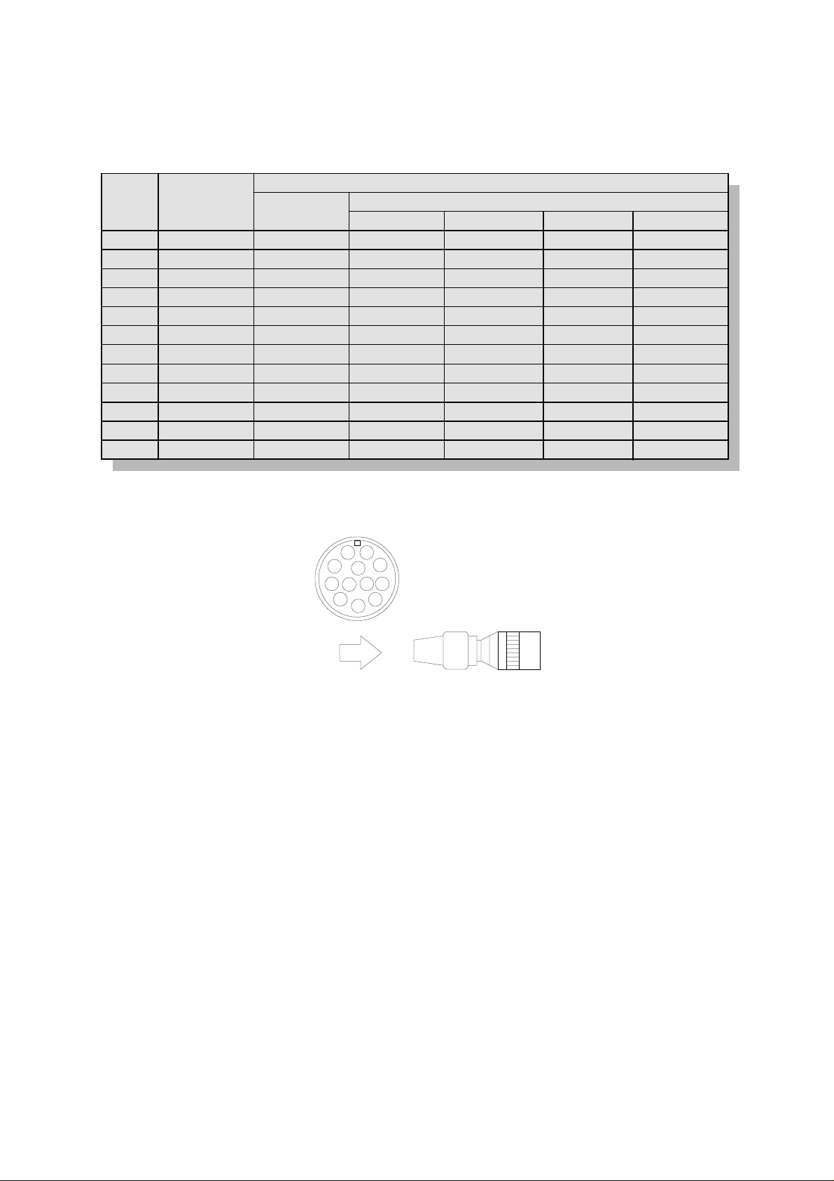
5. Signal connection t o DC IN/SYNC connector.
PIN
NO.
1
2
3
4
5
6
7
8
9
10
11
12
Internal sync
mode
GND
+12V
GND(Vout)
Vout
-
-
-
-
GND
+12V
-
HD/VD
GND
+12V
GND(Vout)
Vout
GND(HD)
HD IN
VD IN
-
-
GND
+12V
GND(VD)
External sync mode
Frame/field on demand
ONE trigger Fixed shutter
GND
+12V
GND(Vout)
Vout
-
-
Trigger A IN
-
-
GND
+12V
GND(Trig A)
TWO trigger EXT shutter
GND
+12V
GND(Vout)
Vout
-
Trigger A IN
GND(Trig B)
Trigger B IN
GND
+12V
GND(Trig A)
GND
+12V
GND(Vout)
Vout
-
-
Trigger A IN
-
GND
+12V
GND(Trig A)
12-pin plug HR10A-10P-12S(01) Product code: 23810AX
1
9
2
3
8
10
7
12
11
4
6
5
GND
+12V
GND(Vout)
Vout
GND(HD)
HD IN
VD IN
GND(Trig B)
Trigger B IN
GND
+12V
GND(VD)
Viewedfromthisside
Note:
The video signal cannot be fed simultaneously from both the VIDEO OUT connector and t he DC
IN/SYNC connector. If both the outputs are connect ed simultaneously, a proper picture cannot be
obtained.
Supply 12V DC in range between 11 and 13V.
KP-M1A
- 7 -
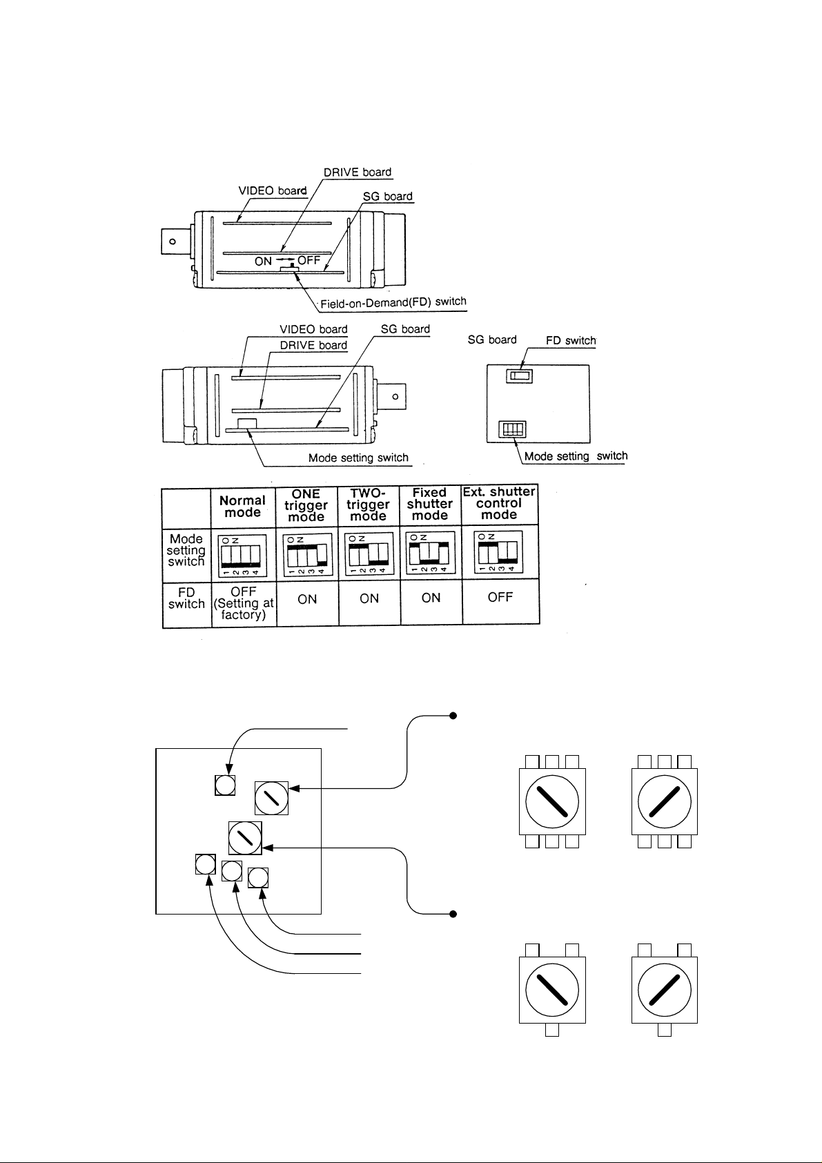
6. Arrangement of internal sw it ches
Internal controls
KP-M1A
GAIN(RV301)
SETUP(RV304)
W.CLIP(RV303)
W.SUP(RV302)
Gammacharacteristic
selectswitch
Factorysettingposition
LENSsideREARside
OFF(gamma=1.0)ON(gamma=0.45)
Gainselectswitch
Factorysettingposition
NormalgainAGC
- 8 -

Gain control Adjusts a video level.
Set to 0.7Vp-p at 400lx, f4. (Gamma: off, AGC: Normal)
SET UP control Adjusts a setup level.
Set to 75 mVp-p. (Gamma: OFF, AGC: Normal)
W.CLI P control Clips a video level.
Set to 1.0Vp-p. (Max: 1.2Vp-p)
W.SUP control Prevents white compression of a video signal and extends a dynamic
range.
Effective when a video level is approximately 120% (Gamma: 1. 0).
(Approx. 110% for Gamma: ON)
KP-M1A
- 9 -
7. External synchronization (2: 1 interlaced)
When operating the camera by external drives signals, connect sync drive signals (HD, VD) to the
DC IN/SYNC connector, then the mode is automatically switched from the internal sync mode to the
external sync mode.
!
Horizontal a nd vertical drive signal inputs
HD EIA: f(H) = 15.734 kHz ±1 %
CCIR: f(H) = 15.625 kHz ±1 %
VD EIA: f(V) = 59.94 Hz (f(V) = f(H) ÷ 262.5)
CCIR: f(V) = 50 Hz (f(V) = f(H) ÷ 312.5)
!
Input level
HD 2 to 6 Vp-p negative
VD 2 to 6 Vp-p negative
!
Input impedance 1 k
!
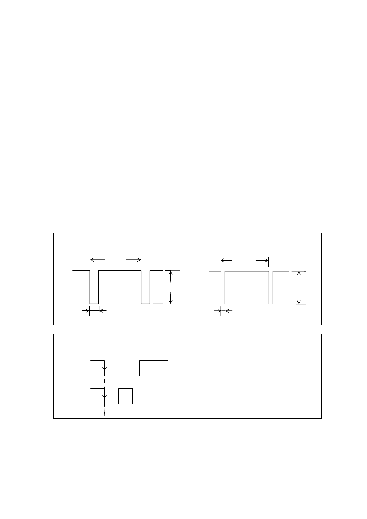
Drive signal input waveform
!
Horizontal drive signal (HD)
T=1/f(H)
Ω
!
Vertical drive signal (VD)
T=1/f(V)
Approx. 6.7µs
!
HD and VD phase relationship
VD
HD
2〜6Vp-p
Approx. 0.6ms(EIA); 0.5ms(CCIR)
Set HD and VD fallings edges to the same phase (0 ± 5 µs)
2〜6Vp-p
KP-M1A
- 10 -
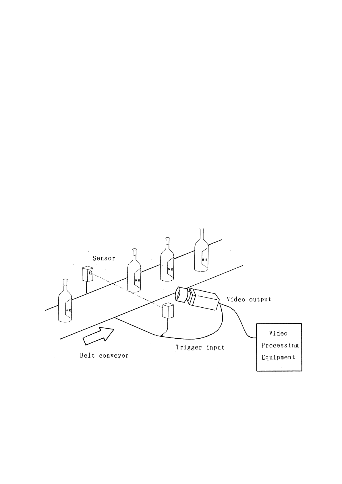
8. Field on demand function
The KP-M1A is provided with the Field-on-Demand function to record a picture obtained at an
optional timing by triggering to an image memory, etc. Four modes are switchable by the internal
switch.
1) ONE trigger mode
2) TWO trigger mode
3) Fixed shutter mode: 1/1600s(EIA) / 1/1000s (CCIR)
4) External shutter control mode
Set the electronic shutter to OFF.
(1) Application
This function is effect ive to shoot moving objects for image processing.
Example: Defect dete ct ion of items on belt conveyer
KP-M1A
- 11 -
 Loading...