

Hitachi Kokusai Electric KP-HD20A Specifications
MODEL
Prod. Code - Order No.
STORED DATE
DESIGNED DATE
CHECKED DATE
APPROVED
DATE
REV.
2 1 3 4
TOLERANCE
SCALE
UNIT
F
E
D
C
B
A
SHEET
1
20
DWG.
No.
TITLE
DF022-4PE-T1
2 1
3
4
F
E
D
C
B
A
CCD Color Camera
KP-HD20A/KP-HD1001/5 Series
Remote control protocol Specifications
(preliminary version)
Hitachi Kokusai Electric Inc.
-
Sep.11.9
(first edition)
Hirayama Hirayama
SYMBOL DATE DESCRIPTION
(DRAWN) DESIGNED
00
KP-HD20A Remote
specification(RS-232C)
KP-HD20A
Series
SHEET
2
10
DF022-4PE-S1
2 1 3 4
F
E
D
C
B
A
F
E
D
C
B
A
2 1
3
4
DWG.
No.
1) Comms* specifications
Sync system Start-stop sync
Bit rate 9600 bps
Data length 8 bits
Start bit 1
Stop bits 1
Parity None
Bit transfer LSB first
*Comms : Communications
*Comms : Communications*Comms : Communications
*Comms : Communications
2) Comms control
The remote control software controls all communications. Data send/receive (BSC
handshake) is by transferring TEXT data to the camera controller chip.
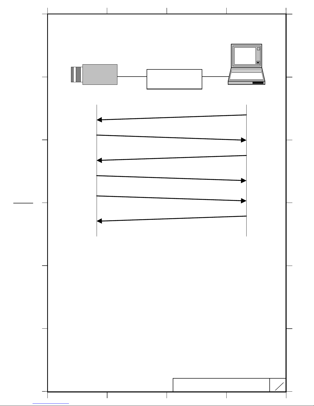
3) Comms connection Scheme
Here is Comms connection Scheme. 3 lines System(Tx,Rx,GND) is applied
(RTS and CTS are not used)
Serial Control recitals
Tx Sending
Rx Reception
GND Ground
4) Comms procedure
The following pages indicate the camera controller chip and remote control software
data protocol. In the description, the camera is designated as slave and the software
as master.
Receive protect timer (time out error)
The receive protect timer for master and slave processes is 1 second. For example,
if 1 block of TEXT data is being received, if the data interval exceeds 1 second,
error is produced and the data are lost. An acknowledgment of data receipt is not
produced.
( Caution )
( Caution )( Caution )
( Caution )
The RS-232C conversion circuit is needed to connect a camera and a remote-controlled
machine (PC etc.) among. Please refer to the product specification for the output pin
on the camera side.

SHEET
3
10
DF022-4PE-S1
2 1 3 4
F
E
D
C
B
A
F
E
D
C
B
A
2 1
3
4
DWG.
No.
a) Transmission from master (normal process)
1) Session starts when ENQ is sent from master to slave.
2) Slave acknowledges by returning ACK to master.
3) Master sends data to slave.
4) Slave acknowledges receipt of data by again returning ACK to master and end the
handshake.
MasterSlave
ENQ code (05H)
1)
ACK code (06H)
Transmit code (ASCII code)
2)
3)
4)
ACK code (06H)
RS
RSRS
RS----232C
232C232C
232C
conversion circuit
conversion circuitconversion circuit
conversion circuit
SHEET
4
10
DF022-4PE-S1
2 1 3 4
F
E
D
C
B
A
F
E
D
C
B
A
2 1
3
4
DWG.
No.
b) Master reads data (normal process)
1) Session starts when ENQ is sent from master to slave.
2) Slave acknowledges by returning ACK to master.
3) Master sends read data command to slave.
4) Slave receives read data command, then acknowledges by returning ACK code to
master.
5) Slave sends read data to master.
6) Master receives read data, then acknowledges by returning ACK code to slave.
MasterSlave
ENQ code (05H)
1)
ACK code (06H)
Read command (ASCII code)
ACK code (06H)
2)
3)
4)
Read data (ASCII code)
ACK code (06H)
5)
6)
RS
RSRS
RS----232C
232C232C
232C
conversion circuit
conversion circuitconversion circuit
conversion circuit
 Loading...