

Page 1

Model Screw Driver
Modèle Visseuse
Modelo Atornillador
W 6VM • W 6V4 • W 6VA4
W 6VB3 • W 8VB2
W6VM • W6V4 • W6VA4 W6VB3 • W8VB2
INSTRUCTION MANUAL AND SAFETY INSTRUCTIONS
WARNING
Improper and unsafe use of this power tool can result in death or serious bodily
injury!
This manual contains important information about product safety. Please read
and understand this manual before operating the power tool. Please keep this
manual available for others before they use the power tool.
MODE D’EMPLOI ET INSTRUCTIONS DE SECURITE
AVERTISSEMENT
Une utilisation incorrecte et dangereuse de cet outil motorisé peut entraîner la
mort ou de sérieuses blessures corporelles!
Ce mode d’emploi contient d’importantes informations à propos de la sécurité de
ce produit. Prière de lire et de comprendre ce mode d’emploi avant d’utiliser l’outil
motorisé. Garder ce mode d’emploi à la disponibilité des autres utilisateurs avant
qu’ils utilisent l’outil motorisé.
MANUAL DE INSTRUCCIONES E INSTRUCCIONES DE SEGURIDAD
ADVERTENCIA
¡La utilización inapropiada e insegura de esta herramienta eléctrica puede resultar
en lesiones serias o en la muerte!
Este manual contiene información importante sobre la seguridad del producto.
Lea y comprenda este manual antes de utilizar la herramienta eléctrica. Guarde
este manual para que puedan leerlo otras personas antes de que utilicen la
herramienta eléctrica.
DOUBLE INSULATION
DOUBLE ISOLATION
AISLAMIENTO DOBLE
Page 2

English
English
IMPORTANT SAFETY INFORMATION
MEANINGS OF SIGNAL WORDS ...... 3
SAFETY ................................................... 4
GENERAL SAFETY RULES.................4
SPECIFIC SAFETY RULES AND SYMBOLS
DOUBLE INSULATION FOR SAFER
OPERATION.....................................8
FUNCTIONAL DESCRIPTION ................ 9
NAME OF PARTS................................9
SPECIFICATIONS ................................ 9
Français
INFORMATIONS IMPORTANTES DE SÉCURITÉ
SIGNIFICATION DES MOTS
D’AVERTISSEMENT ......................... 17
SECURITE ............................................. 18
REGLES GENERALES DE SECURITE
REGLES DE SECURITE SPECIFIQUES ET SYMBOLES
DOUBLE ISOLATION POUR UN
FONCTIONNEMENT PLUS SUR
DESCRIPTION FONCTIONNELLE ........ 24
NOM DES PARTIES .......................... 24
SPECIFICATIONS .............................. 24
TABLE DES MATIERES
CONTENTS
Page
..... 3
..... 6
Page
... 17
..... 18
... 20
........ 23
ASSEMBLY AND OPERATION ............ 10
MAINTENANCE AND INSPECTION .... 14
ACCESSORIES ...................................... 15
PART LIST ............................................. 48
ASSEMBLAGE ET FONCTIONNEMENT ....
ENTRETIEN ET INSPECTION ............... 29
ACCESSOIRES ...................................... 30
LISTE DES PIECES ............................... 48
Page
APPLICATIONS ................................. 10
PRIOR TO OPERATION..................... 10
HOW TO USE THE SCREW DRIVER...
MOUNTING AND DISMOUNTING
THE HEX-SOCKET OR BIT ........... 13
STANDARD ACCESSORIES ............. 15
OPTIONAL ACCESSORIES............... 16
APPLICATIONS ................................. 25
AVANT L’UTILISATION .................... 25
COMMENT UTILISER LA VISSEUSE
MONTAGE ET DEMONTAGE DU MANCHON
SIX PANS OU DE LA MECHE
ACCESSOIRES STANDARD ............. 30
ACCESSOIRES SUR OPTION........... 31
.................
12
Page
25
.. 27
28
Español
INFORMACIÓN IMPORTANTE SOBRE SEGURIDAD
SIGNIFICADO DE LAS PALABRAS DE
SEÑALIZACIÓN................................. 32
SEGURIDAD ......................................... 33
NORMAS GENERALES DE SEGURIDAD
NORMAS Y SÍMBOLOS ESPECÍFICOS DE SEGURIDAD
AISLAMIENTO DOBLE PARA OFRECER UNA
OPERACIÓN MÁS SEGURA
DESCRIPCIÓN FUNCIONAL ................ 39
NOMENCLATURA............................. 39
ESPECIFICACIONES.......................... 39
2
................... 38
ÍNDICE
Página
... 32
... 33
..... 35
Página
MONTAJE Y OPERACIÓN ................... 40
APLICACIONES ................................. 40
ANTES DE LA OPERACIÓN .............. 40
COMO USAR EL DESTORNILLADOR
MONTAJE Y DESMONTAJE DEL PORTATORNILLOS
MANTENIMIENTO E INSPECCIÓN ..... 45
ACCESORIOS ....................................... 46
ACCESORIOS ESTÁNDAR ............... 46
ACCESORIOS OPCIONALES............ 47
LISTA DE PIEZAS ................................. 48
HEXAGONAL O DE LA BROCA
................... 44
... 42
Page 3

English
IMPORTANT SAFETY INFORMATION
Read and understand all of the safety precautions, warnings and operating
instructions in the Instruction Manual before operating or maintaining this power
tool.
Most accidents that result from power tool operation and maintenance are caused
by the failure to observe basic safety rules or precautions. An accident can often be
avoided by recognizing a potentially hazardous situation before it occurs, and by
observing appropriate safety procedures.
Basic safety precautions are outlined in the “SAFETY” section of this Instruction
Manual and in the sections which contain the operation and maintenance
instructions.
Hazards that must be avoided to prevent bodily injury or machine damage are
identified by WARNINGS on the power tool and in this Instruction Manual.
NEVER use this power tool in a manner that has not been specifically recommended
by HITACHI.
MEANINGS OF SIGNAL WORDS
WARNING indicates a potentially hazardous situations which, if ignored, could result
in death or serious injury.
CAUTION indicates a potentially hazardous situations which, if not avoided, may
result in minor or moderate injury, or may cause machine damage.
NOTE emphasizes essential information.
3
Page 4

English
SAFETY
GENERAL SAFETY RULES
WARNING: Read and understand all instructions.
Failure to follow all instructions listed below, may result in electric
shock, fire and/or serious personal injury.
SAVE THESE INSTRUCTIONS
1. Work Area
(1) Keep your work area clean and well lit. Cluttered benches and dark areas
invite accidents.
(2) Do not operate power tools in explosive atmospheres, such as in the
presence of flammable liquids, gases, or dust. Power tools create sparks
which may ignite the dust of fumes.
(3) Keep bystanders children, and visitors away while operating a power tool.
Distractions can cause you to lose control.
2. Electrical Safety
(1) Double Insulated tools are equipped with a polarized plug (one blade is
wider than the other.) This plug will fit in a polarized outlet only one way.
If the plug does not fit fully in the outlet, reverse the plug. If it still does not
fit, contact a qualified electrician to install a polarized outlet. Do not change
the plug in any way. Double Insulation
wire grounded power cord and grounded power supply system.
(2) Avoid body contact with grounded surfaces such as pipes, radiators, ranges
and refrigerators. There is an increased risk of electric shock if your body is
grounded.
(3) Do not expose power tools to rain or wet conditions. Water entering a
power tool will increase the risk of electric shock.
(4) Do not abuse the cord. Never use the cord to carry the tools or pull the
plug from a receptacle. Keep cord away from heat, oil, sharp edges or
moving parts. Replace damaged cords immediately. Damaged cords
increase the risk of electric shock.
(5) When operating a power tool outside, use an outdoor extension cord
marked “W-A” or “W”. These cords are rated for outdoor use and reduce
the risk of electric shock.
3. Personal Safety
(1) Stay alert, watch what you are doing and use common sense when
operating a power tool. Do not use tool while tires or under the influence
of drugs, alcohol, or medication. A moment of inattention while operating
power tools may result in serious personal injury.
(2) Dress properly. Do not wear loose clothing or jewelry. Contain long hair.
Keep your hair, clothing and gloves away from moving parts. Loose clothes,
jewelry, or long hair can be caught in moving parts.
4
eliminates the need for the three
Page 5

(3) Avoid accidental starting. Be sure switch is off before plugging in. Carrying
tools with your finger on the switch or plugging in tools that have the switch
on invites accidents.
(4) Remove adjusting keys or wrenches before turning the tool on. A wrench
or a key that is left attached to a rotating part of the tool may result in
personal injury.
(5) Do not overreach. Keep proper footing and balance at all times. Proper
footing and balance enables better control of the tool in unexpected
situations.
(6) Use safety equipment. Always wear eye protection. Dust mask, non-skid
safety shoes, hard hat, or hearing protection must be used for appropriate
conditions.
4. Tool Use and Care
(1) Use clamps or other practical way to secure and support the workpiece to
a stable platform. Holding the work by hand or against your body is unstable
and may lead to loss of control.
(2) Do not force tool. Use the correct tool for your application. The correct tool
will do the job better and safer at the rate for which it is designed.
(3) Do not use tool if switch does not turn it on or off. Any tool that cannot be
controlled with the switch is dangerous and must be repaired.
(4) Disconnect the plug form the power source before making any adjustments,
changing accessories, or storing the tool. Such preventive safety measures
reduce the risk of starting the tool accidentally.
(5) Store idle tools out of reach of children and other untrained persons. Tools
are dangerous in the hands of untrained users.
(6) Maintain tools with care. Keep cutting tools sharp and clean. Properly
maintained tools, with sharp cutting edges are less likely to bind and are
easier to control.
(7) Check for misalignment or binding of moving parts, breakage of parts, and
any other condition that may affect the tool's operation. If damaged, have
the tool serviced before using. Many accidents are caused by poorly
maintained tools.
(8) Use only accessories that are recommended by the manufacturer for your
model. Accessories that may be suitable for one tool, may become hazardous
when used with another tool.
5. Service
(1) Tool service must be performed only by qualified repair personnel. Service
or maintenance performed by unqualified personnel could result in a risk of
injury.
(2) When servicing a tool, use only identical replacement parts. Follow
instructions in the Maintenance section of this manual. Use of unauthorized
parts or failure to follow Maintenance Instruction may create a risk of electric
shock or injury.
English
5
Page 6
English
SPECIFIC SAFETY RULES AND SYMBOLS
1. Hold tools by insulated gripping surfaces when performing an operation where
the cutting tool may contact hidden wiring or its own cord. Contact with a
“live” wire will make exposed metal parts of the tool “live” and shock the
operator.
2. ALWAYS wear ear protectors when using the tool for extended periods.
Prolonged exposure to high intensity noise can cause hearing
loss.
3. Employ a driver bit appropriate for the screw diameter.
4. Apply the screw driver body perpendicularly to a screw head when driving a
screw.
5. NEVER touch moving parts.
NEVER place your hands, fingers or other body parts near the tool’s moving
parts.
6. NEVER operate without all guards in place.
NEVER operate this tool without all guards or safety features in place and in
proper working order. If maintenance or servicing requires the removal of a
guard or safety feature, be sure to replace the guard or safety feature before
resuming operation of the tool.
7. Use right tool.
Don’t force small tool or attachment to do the job of a heavy-duty tool.
Don’t use tool for purpose not intended —for example— don’t use circular saw
for cutting tree limbs or logs.
8. NEVER use a power tool for applications other than those specified.
NEVER use a power tool for applications other than those specified in the
Instruction Manual.
9. Handle tool correctly.
Operate the tool according to the instructions provided herein. Do not drop or
throw the tool. NEVER allow the tool to be operated by children, individuals
unfamiliar with its operation or unauthorized personnel.
10. Keep all screws, bolts and covers tightly in place.
Keep all screws, bolts, and plates tightly mounted. Check their condition
periodically.
11. Do not use power tools if the plastic housing or handle is cracked.
Cracks in the tool’s housing or handle can lead to electric shock. Such tools
should not be used until repaired.
12. Blades and accessories must be securely mounted to the tool.
Prevent potential injuries to youself or others. Blades, cutting implements and
accessories which have been mounted to the tool should be secure and tight.
6
Page 7

13. Keep motor air vent clean.
The tool’s motor air vent must be kept clean so that air can freely flow at all
times. Check for dust build-up frequently.17. Never leave tool running
unattended. Turn power off.
14. Operate power tools at the rated voltage.
Operate the power tool at voltages specified on its nameplate.
If using the power tool at a higher voltage than the rated voltage, it will result in
abnormally fast motor revolution and may damage the unit and the motor may
burn out.
15. NEVER use a tool which is defective or operating abnormally.
If the tool appears to be operating unusually, making strange noises, or otherwise
appears defective, stop using it immediately and arrange for repairs by a Hitachi
authorized service center.
16. NEVER leave tool running unattended. Turn power off.
Don’t leave tool until it comes to a complete stop.
17. Carefully handle power tools.
Should a power tool be dropped or struck against hard materials inadvertently,
it may be deformed, cracked, or damaged.
18. Do not wipe plastic parts with solvent.
Solvents such as gasoline, thinner benzine, carbon tetrachloride, and alcohol
may damage and crack plastic parts. Do not wipe them with such solvents.
Wipe plastic parts with a soft cloth lightly dampened with soapy water and dry
thoroughly.
19. Definitions for symbols used on this tool.
V ... volts
Hz ... hertz
A ... amperes
o ... no load speed
n
W ... watt
... Class II Consruction
- - -/min ... revolutions per minute
English
7
Page 8

English
DOUBLE INSULATION FOR SAFER OPERATION
To ensure safer operation of this power tool, HITACHI has adopted a double insulation
design. “Double insulation” means that two physically separated insulation systems
have been used to insulate the electrically conductive materials connected to the
power supply from the outer frame handled by the operator. Therefore, either the
symbol “
nameplate.
Although this system has no external grounding, you must still follow the normal
electrical safety precautions given in this Instruction Manual, including not using
the power tool in wet environments.
To keep the double insulation system effective, follow these precautions:
䡬 Only Hitachi Authorized Service Center should disassemble or assemble this
power tool, and only genuine HITACHI replacement parts should be installed.
䡬 Clean the exterior of the power tool only with a soft cloth moistened with soapy
water, and dry thoroughly.
Never use solvents, gasoline or thinners on plastic components; otherwise the
plastic may dissolve.
” or the words “Double insulation” appear on the power tool or on the
SAVE THESE INSTRUCTIONS
AND
MAKE THEM AVAILABLE TO
OTHER USERS
AND
OWNERS OF THIS TOOL!
8
Page 9
FUNCTIONAL DESCRIPTION
NOTE:
The information contained in this Instruction Manual is designed to assist you in
the safe operation and maintenance of the power tool.
NEVER operate, or attempt any maintenance on the tool unless you have first
read and understood all safey instructions contained in this manual.
Some illustrations in this Instruction Manual may show details or attachments
that differ from those on your own power tool.
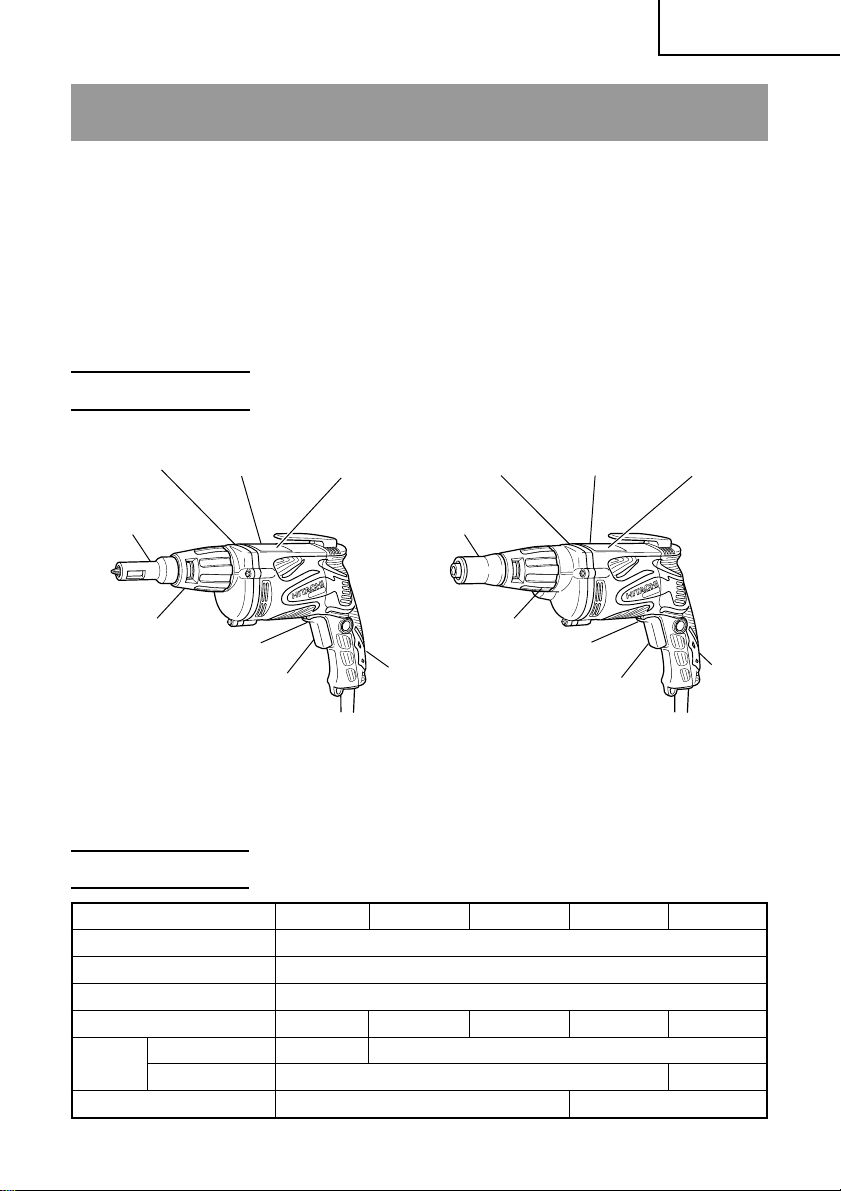
NAME OF PARTS
English
Gear Cover
Sub-Stopper (F)
Locator
W6VM • W6V4 • W6VA4 W6VB3 • W8VB2
Housing
Lever
Switch
Nameplate
Gear Cover Housing
Sub-Stopper (B)
Locator
Handle Cover
Fig. 1
Lever
Switch
Nameplate
Handle
Cover
SPECIFICATIONS
Model W6VM W6V4 W6VA4 W6VB3 W8VB2
Motor Single-Phase, Series Commutator Motor
Power Source Single-Phase, 120 V 60 Hz
Current 6.5 A
No-Load Speed
Capacity
Weight 3.1 lbs (1.4 kg) 3.3 lbs (1.5 kg)
Drywall screw
Self-drilling screw
0–6000/min. 0–4500/min. 0–3000/min. 0–2600/min. 0–1700/min.
3/16” (5 mm)
1/4” (6 mm)
1/4” (6 mm)
5/16” (8 mm)
9
Page 10
English
ASSEMBLY AND OPERATION
APPLICATIONS
䡬 Tightening hex. head screws
䡬 Tightening Drywall screws, wood screws and self-drilling screws
NOTE:
For tightening the Self-drilling screws, sub-stopper (B) and non-magnetic bit holder
(sold separately) are recommended.
PRIOR TO OPERATION
1. Power source
Ensure that the power source to be utilized conforms to the power source requirements specified on the product nameplate.
2. Power switch
Ensure that the switch is in the OFF position. If the plug is connected to a receptacle while the switch is in the ON position, the power tool will start operating
immediately and can cause serious injury.
3. Extension cord
When the work area is far away from the power source, use an extension cord of
sufficient thickness and rated capacity. The extension cord should be kept as
short as practicable.
WARNING:
Damaged cord must be replaced or repaired.
4. Check the receptacle
If the receptacle only loosely accepts the plug, the receptacle must be repaired.
Contact a licensed electrician to make appropriate repairs.
If such a fautly receptacle is used, it may cause overheating, resulting in a serious hazard.
5. Confirming condition of the environment
Confirm that the work site is placed under appropriate conditions conforming to
prescribed precautions.
10
Page 11
English
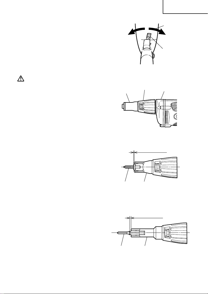
6. Confirm the direction of bit rotation
(Fig. 2)
The bit rotates clockwise (viewed from
the rear side) when the reversing
switch lever is set to the “R” side position. When the lever is set to the “L”
side position, the bit rotates counterclockwise and can be used to loosen
and remove screws.
CAUTION:
Never change the bit rotating direction
while operating the Screw Driver. Turn
the main switch off before changing
the rotating direction, otherwise, burning of the motor will result.
7. Adjusting the tightening depth
(Fig. 3)
The tightening depth can be adjusted
by turning locator right and left with
click feeling.
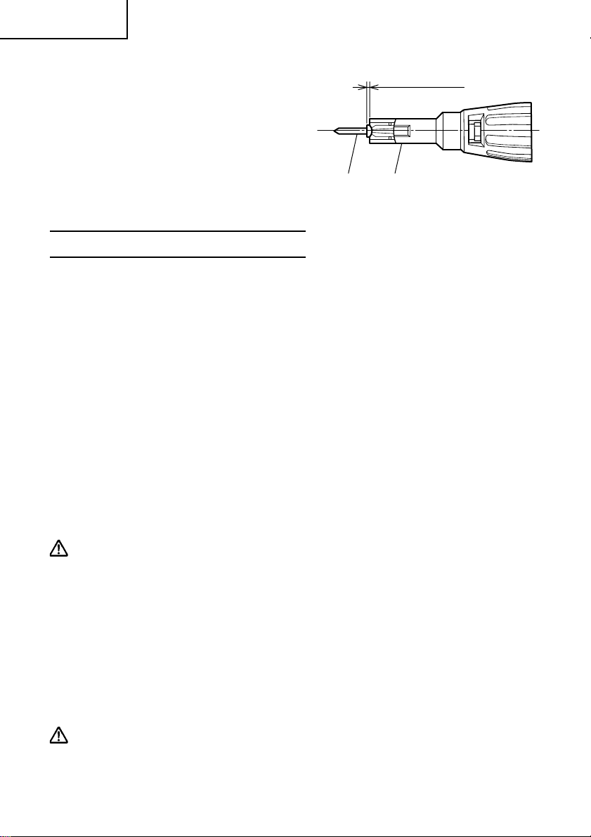
(1) For hex-head screws (Fig. 4)
Mount a hex-head screw on the hexsocket and set the distance between the
sub-stopper end and the screw head
neck to 0.04” – 0.06” (1 – 1.5 mm).
(2) For drywall screws (Fig. 5)
Mount a drywall screw on the bit, and
set the distance between the sub-stopper end and the screw head to 0.06” –
0.07” (1.5 – 2 mm).
(3) For cross-recessed self-drilling screws
(Fig. 6)
Mount a self-drilling screw on the bit,
and set the distance between the substopper end and the screw head bottom to 0.04” – 0.06” (1 – 1.5 mm).
Sub
Stopper (B)
Hex. head
screw
Lever
Fig. 2
Locator
Gear cover
Fig. 3
0.04" – 0.06"
(1 – 1.5 mm)
Sub-Stopper (B)
Fig. 4
0.06" – 0.07"
(1.5 – 2 mm)
R side
Drywall screw
Sub-Stopper (F)
Fig. 5
11
Page 12
English
8. Mounting the bit
For details, refer to the item “Mounting and dismounting the hex-socket or
the bit”.
Self-drilling screw Sub-Stopper (F)
0.04" – 0.06"
(1 – 1.5 mm)
Fig. 6
HOW TO USE THE SCREW DRIVER
1. Switch operation and rotational speed adjustment
Bit rotational speed can be adjusted between 0–6000/min (W6VM) or 0–4500/min
(W6V4) or 0–3000/min (W6VA4) or 0–2600/min (W6VB3) or 0–1700/min (W8VB2)
varying the degree by which the trigger switch is pulled. Rotational speed increases
as the trigger switch is pulled, and reaches a maximum speed of 6000/min (W6VM)
or 4500/min (W6V4) or 3000/min (W6V A4) or 2600/min (W6VB3) or 1700/min (W8VB2)
when the trigger switch is pulled fully.
To facilitate continuous operation, pull the trigger switch and depress the switch
stopper. The switch will then remain ON even when the finger is released. By
pulling the trigger switch again, the switch stopper disengages and the switch is
turned OFF when the trigger switch is released.
2. Screw Driver operation
When the switch is turned ON, the motor starts to run but the hex-socket (or the
bit) does not rotate. Attach the hex-socket to the screw head groove, and push
the Screw Driver against the screw. The hex-socket then rotates and tightens the
screw.
CAUTION
Ensure that the Screw Driver is held truly perpendicular to the head of the screw.
If held at an angle, the driving force will not be fully transferred to the screw,
and the screw head and/or hex-socket will be damaged. Hex-socket rotation
stops when pushing force is released.
3. Direction of hex-socket rotation
The hex-socket rotates clockwise (viewed from the rear side) when the reversing switch lever is set to the “R” side position. When the lever is set to the “L”
side position, the hex-socket rotates counterclockwise, and can be used to loosen
and remove screws.
CAUTION
Never change the direction of hex-socket (or bit holder) rotation while the motor is running. To do so would seriously damage the motor. Turn the power
switch OFF before changing the direction of hex-socket (or bit holder) rotation.
12
Page 13
English
4. Tightening Self-drilling screw
When the supplied magnet bit holder is used to tighten the Self-drilling screw
into a steel plate, cut material stuck in the magnet bit will degrade the work
efficiency.
To prevent this, the non-magnetic bit holder (optional accessory) is recommended. The stainless locator with bushing (optional accessory) will prevent
the bushing from being worn.
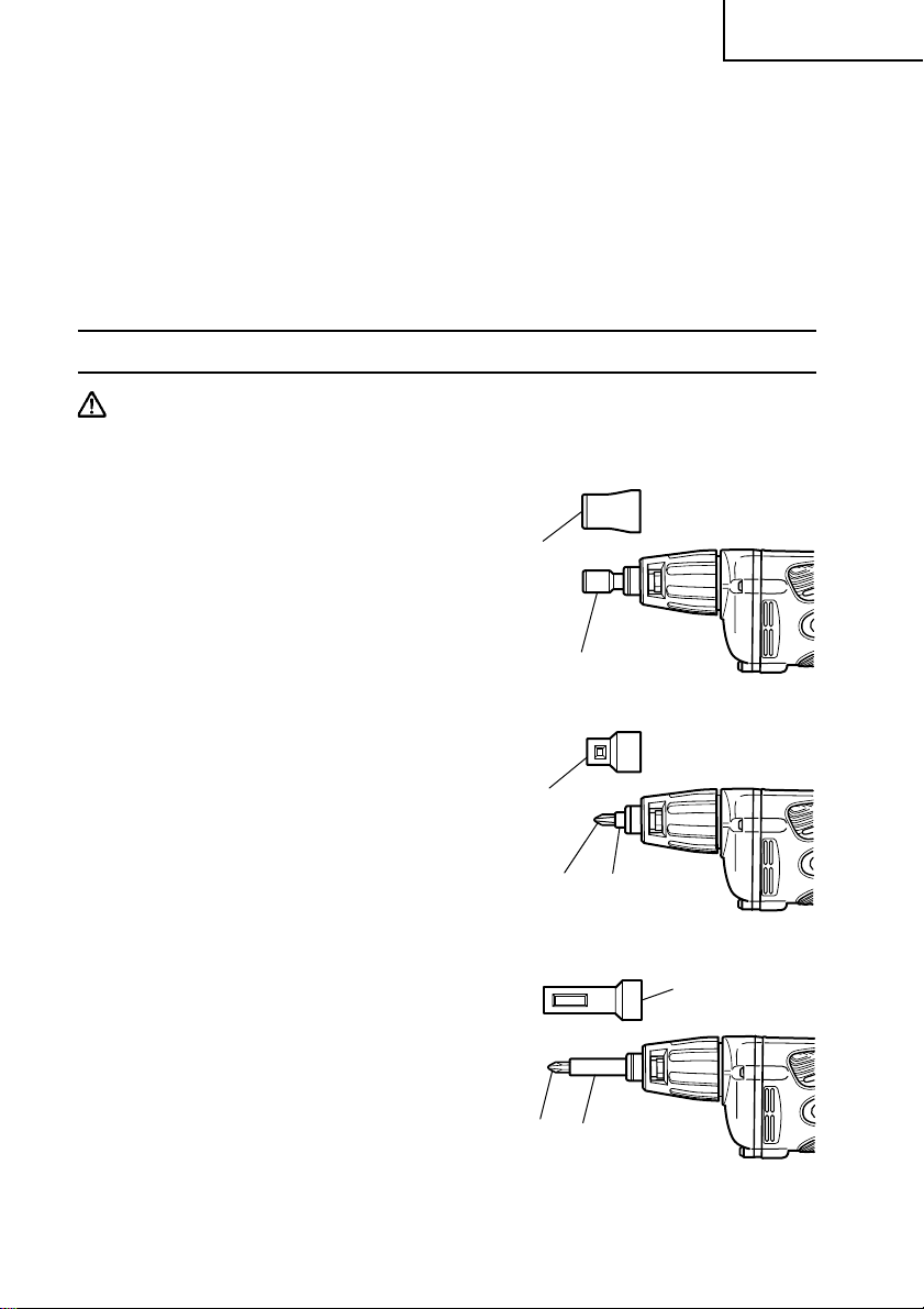
MOUNTING AND DISMOUNTING THE HEX-SOCKET OR THE BIT
CAUTION
Be sure to switch power OFF and disconnect the plug from receptacle to avoid
serious trouble.
1. Dismounting the hex-socket (Fig. 7)
(1) While rotating the Sub-Stopper pull it
out from the locator.
(2) Remove the hex-socket, hold it with the
opposite side of bit by hand or vise and
pull out the bit with pliers.
2. Dismounting the bit (Fig. 8)
Remove sub-stopper (G) as the same
manner of hex-head socket and remove
the bit holder , then pull out the bit with
pliers.
3. Dismounting the bit (Fig. 9)
Remove the sub-stopper (F) as the
same manner of hex-head socket and
remove the bit holder , then pull out the
bit with pliers.
4. Mounting the hex-socket or the bit
Install the bit in the reverse order to
removal.
Sub-Stopper (B)
Magnetic hex. socket
Sub-Stopper (G)
Bit holder
Bit
(Short type)
Fig. 7
Fig. 8
Sub-Stopper (F)
Bit
Bit holder
Fig. 9
13
Page 14
English
MAINTENANCE AND INSPECTION
WARNING: Be sure to switch power OFF and disconnect the plug from the
receptacle during maintenance and inspection.
1. Inspecting the hex. socket (or bit)
Since continued use of a worn hex. socket (bit) will damage screw heads, replace the hex. socket (bit) with a new one as soon as excessive wear is noticed.
2. Inspecting the screws
Regularly inspect all screws and ensure that they are properly tightened. Should
any of the screws be loosened, retighten them immediately.
WARNING: Using this screw driver with loosened screws is extremely
dangerous.
3. Maintenance of the motor
The motor unit winding is the very “heart” of the power tool. Exercise due care
to ensure the winding does not become damaged and/or wet with oil or water.
4. Cleaning the unit exterior
Wipe off oil and stain on the unit exterior with a dried rag or a rag moistened
with soapy water.
5. Inspecting the carbon brushes
For your continued safety and electrical shock protection, carbon brush inspection and replacement on this tool should ONLY be performed by a Hitachi
Authorized Service Center.
6. Service and repairs
All quality power tools will eventually require servicing or replacement of parts
because of wear from normal use. To assure that only authorized replacement
parts will be used, all service and repairs must be performed by a Hitachi
Authorized Service Center, ONLY.
7. Service parts list
A: Item No.
B: Code No.
C: No. Used
D: Remarks
CAUTION: Repair, modification and inspection of Hitachi Power Tools must be
carried out by a Hitachi Authorized Service Center.
This Parts List will be helpful if presented with the tool to the Hitachi
Authorized Service Center when requesting repair or other
maintenance. In the operation and maintenance of power tools, the
safety regulations and standards prescribed in each country must
be observed.
14
Page 15

English
MODIFICATIONS:
Hitachi Power Tools are constantly being improved and modified to incorporate
the latest technological advancements.
Accordingly, some parts (i.e. code numbers and/or design) may be changed
without prior notice.
ACCESSORIES
WARNING: ALWAYS use Only authorized HITACHI replacement parts and
accessories. NEVER use replacement parts or accessories which
are not intended for use with this tool. Contact HITACHI if you
are not sure whether it is safe to use a particular replacement
part or accessory with your tool.
The use of any other attachment or accessory can be dangerous
and could cause injury or mechanical damage.
NOTE:
Accessories are subject to change without any obligation on the part of the HIT ACHI.
STANDARD ACCESSORIES
<W6VM • W6V4 • W6VA4>
(1) No. 2 Phillips driver bit (Code No. 971511Z) .........................................................1
(2) Magnetic bit holder (Code No. 982554Z) ...............................................................1
(3) Sub-stopper (F) (Code No. 323351) ........................................................................1
<W6VB3 • W8VB2>
(1) Magnetic hex. socket (H=5/16” (7.94 mm)) (Code No. 985322) ...........................1
(2) Sub-stopper (B) (H=5/16” (7.94 mm)) (Code No. 317671) ....................................1
15
Page 16
English
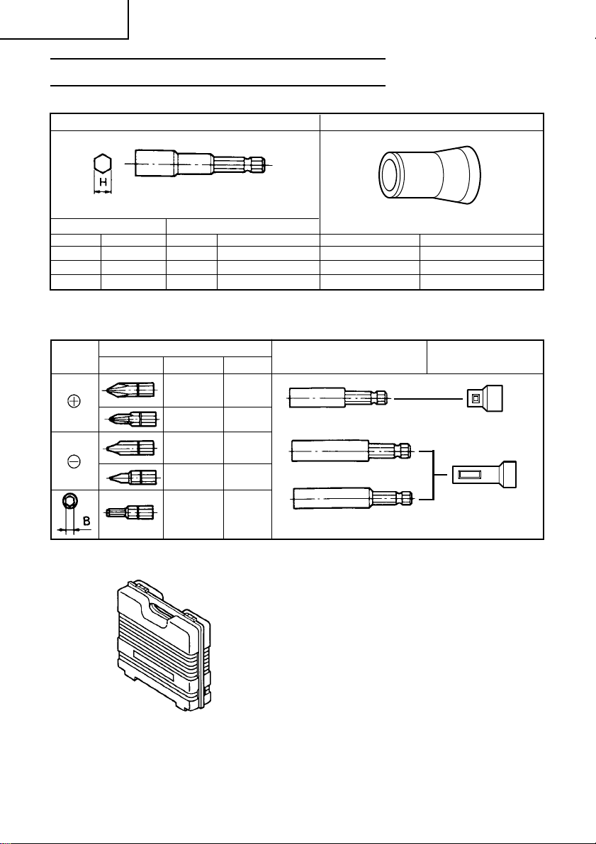
OPTIONAL ACCESSORIES...........sold separately
1. For hex-head screws
Hex-socket Sub-Stopper (B)
Magnetic type Non magnetic type
Size Code No. Size Code No. Size Code No.
H 1/4 985332 H 1/4 985328 H 1/4 317827
H 5/16 985322 H 5/16 985327 H 5/16 317671
H 3/8 985330 H 3/8 985326 H 3/8 317670
2. For other screws
Screw
head
Type Size
Bit
No.1 985333
No.2 971511Z
No.3 971512Z
No.1 985334
No.2 985335
No.1 985336
No.2 985337
No.3 985338
No.1 985340
No.2 985341
B Size
5/32” (4 mm)
13/64” (5 mm)
Code No.
985342
985343
Bit holder
Magnetic bit holder
(Short type)
Magnetic bit holder
(Code No. 982554Z)
Non-magnetic bit bolder
(Code No. 982563Z)
Sub-Stopper
Sub-Stopper (G)
(Code No. 323352)
Sub-Stopper (F)
(Code No. 323351)
3. Plastic case (Code No. 310504)
NOTE:
Specifications are subject to change without any obligation on the part of the
HITACHI.
16
Page 17

Français
INFORMATIONS IMPORTANTES DE SÉCURITÉ
Lire et comprendre toutes les précautions de sécurité, les avertissements et les
instructions de fonctionnement dans ce mode d’emploi avant d’utiliser ou d’entretenir
cet outil motorisé.
La plupart des accidents causés lors de l’utilisation ou de l’entretien de l’outil
motorisé proviennent d’un non respect des règles ou précautions de base de
sécurité. Un accident peut la plupart du temps être évité si l’on reconnaît une
situation de danger potentiel avant qu’elle ne se produise, et en observant les
procédures de sécurité appropriées.
Les précautions de base de sécurité sont mises en évidence dans la section
“SECURITE” de ce mode d’emploi et dans les sections qui contiennent les instructions de fonctionnement et d’entretien.
Les dangers qui doivent être évités pour prévenir des blessures corporelles ou un
endommagement de la machine sont identifiés par AVERTISSEMENTS sur l’outil
motorisé et dans ce mode d’emploi.
NE JAMAIS utiliser cet outil motorisé d’une manière qui n’est pas spécifiquement
recommandée par HITACHI.
SIGNIFICATION DES MOTS D’AVERTISSEMENT
AVERTISSEMENT indique des situations potentiellement dangereuses qui, si elles
sont ignorées, pourraient entraîner la mort ou de sérieuses blessures.
PRECAUTION indique des situations dangereuses potentilles qui, si elles ne sont pas
évitées, peuvent entraîner de mineures et légères blessures ou endommager la
machine.
REMARQUE met en relief des informations essentielles.
17
Page 18

Français
SECURITE
REGLES GENERALE DE SECURITE
AVERTISSEMENT: Lire et coxmprendre toutes les instructions.
Un non respect de toutes les instructions ci-dessous
peut entraîner une électrocution, un incendie et/ou de
sérieuses blessures personnelles.
CONSERVER CES INSTRUCTIONS
1. Zone de travail
(1) Garder la zone de travail propre et bien éclairée. Les établis mal rangés et
les zones sombres invitent aux accidents.
(2) Ne pas utiliser les outils motorisés dans une atmosphère explosive, telle
qu’en présence de liquides inflammables, de gaz ou de poussières. Les outils
motorisés créent des étincelles qui risquent d’enflammer la poussière ou
les vapeurs.
(3) T enir les spectateurs, les enfants et les visiteurs éloignés, lors de l’utilisation
de l’outil motorisé. Une distraction peut faire perdre le contrôle de la machine.
2. Sécurité électrique
(1) Les outils à double isolation sont équipés d’une fiche polarisée (une lame
est plus large que l’autre). Cette fiche ne pénétrera dans une prise secteur
polarisée que dans un sens. Si la fiche ne rentre pas complètement dans la
prise, la retourner. Si elle ne rentre toujours pas, contacter un électricien
qualifié pour installer une prise polarisée. Ne pas modifier la fiche d’aucune
façon. La double isolation
trois fils et d’un système d’alimentation avec mises à la terre.
(2) Eviter tout contact corporel avec les surfaces mises à la terre telles que les
canalisations, les radiateurs, les réchauds et les réfrigérateurs. Il y a un risque
accru d’électrocution si son corps est mis à la terre.
(3) Ne pas exposer les outils motorisés à la pluie ou à l’humidité. De l’eau
pénétrant à l’intérieur de l’outil motorisé augmente le risque d’électrocution.
(4) Ne pas maltraiter le cordon d’alimentation. Ne jamais utiliser le cordon pour
porter les outils ou tirer sur la fiche du réceptacle. Garder le cordon à l’écart
de la chaleur , de l’huile, des arêtes coupantes ou des pièces en mouvement.
Remplacer les cordons endommagés immédiatement. Des cordons
endommagés augmentent le risque d’électrocution.
(5) Lors de l’utilisation d’un outil motorisé, utiliser un cordon de rallonge
extérieur marqué “W-A” ou “W”. Ces cordons sont prévus pour une
utilisation extérieure et réduisent les risques d’électrocution.
élimine le besoin d’un cordon d’alimentation à
18
Page 19

3. Sécurité personnelle
(1) Rester sur ses gardes, regarder ce que l’on fait et utiliser son sens commun
lors de l’utilisation d’un outil motorisé. Ne pas utiliser un outil en état de
fatigue ou sous l’influence de drogues, d’alcool ou de médicaments. Un
moment d’inattention lors de l’utilisation de l’outil motorisé peut entraîner
de sérieuses blessures personnelles.
(2) S’habiller correctement. Ne pas porter des vêtements larges ou des bijoux.
Attacher les cheveux longs. Tenir ses cheveux, vêtements et ses gants
éloignés des parties mobiles. Les vêtements larges, les bijoux et les cheveux
longs peuvent se prendre dans les parties mobiles.
(3) Eviter tout démarrage accidentel. S’assurer que le l’interrupteur
d’alimentation est sur la position d’arrêt avant de brancher la machine.
Transporter l’appareil avec les doigts sur l’interrupteur d’alimentation ou
brancher un outil avec l’interrupteur sur la position marche invite aux
accidents.
(4) Retirer les clefs d’ajustement ou les commutateurs avant de mettre l’outil
sous tension. Une clef qui est laissée attachée à une partie tournante de
l’outil peut provoquer une blessure personnelle.
(5) Ne pas trop présumer de ses forces. Garder en permanence une position et
un équilibre correct. Une position et un équilibre correct permettent un
meilleur contrôle de l’outil dans des situations inattendues.
(6) Utiliser un équipement de sécurité. T oujours porter une protection pour les
yeux. Utiliser un masque à poussière, des chaussures de sécurité
antidérapantes, un casque dur et une protection pour les oreilles dans les
conditions appropriées.
4. Utilisation de l’outil et entretien
(1) Utiliser un étau ou toutes autres façons de fixer et maintenir la pièce à
usiner sur une plate-forme stable. Tenir la pièce avec la main ou contre son
corps est instable et peut conduire à une perte de contrôle de l’outil.
(2) Ne pas forcer sur l’outil. Utiliser l’outil correct pour l’application souhaitée.
L’outil correct réalisera un meilleur et plus sûr travail dans le domaine pour
lequel il a été conçu.
(3) Ne pas utiliser un outil s’il ne se met pas sous ou hors tension avec un
interrupteur. Un outil qui ne peut pas être commandé avec un interrupteur
est dangereux et doit être réparé.
(4) Déconnecter la fiche de la source d’alimentation avant de réaliser tout
ajustement, changement d’accessoires ou pour ranger l’outil. De telles
mesures de sécurité réduisent le risque que l’outil ne démarre
accidentellement.
(5) Ranger les outils inutilisés hors de la portée des enfants et des autres
personnes inexpérimentées. Les outils sont dangereux dans les mains de
personnes inexpérimentées.
(6) Utiliser un équipement de sécurité. Toujours porter des lunettes de
protection. Utiliser un masque à poussière, des chaussures de sécurité
Français
19
Page 20

Français
antidérapantes, un couvre-chef dur ou des protections de l’ouïe dans les
conditions appropriées.
(7) Vérifier les défauts d’alignement ou grippage des parties mobiles, les
ruptures des pièces et toutes les autres conditions qui peuvent affecter le
fonctionnement des outils. En cas de dommage, faire réparer l’outil avant
de l’utiliser . Beaucoup d’accidents sont causés par des outils mal entretenus.
(8) Utiliser uniquement les accessoires recommandés par le fabricant pur le
modèle utilisé. Des accessoires qui peuvent convenir à un outil, peuvent
devenir dangereux lorsqu’ils sont utilisés avec un autre outil.
5. Réparation
(1) La réparation de l’outil ne doit être réalisée uniquement par un réparateur
qualifié. Une réparation ou un entretien réalisé par un personnel non qualifié
peut entraîner des risques de blessures.
(2) Lors de la réparation d’un outil, utiliser uniquement des pièces de rechange
identiques. Suivre les instructions de la section d’entretien de ce mode
d’emploi. L’utilisation de pièces non autorisées ou un non respect des
instructions d’entretien peut créer un risque d’électrocution ou de blessures.
REGLES DE SECURITE SPECIFIQUES ET SYMBOLES
1. Tenir les outils par les surfaces de grippage lors de la réalisation d’opération où
l’outil de coupe risque d’entrer en contact avec des câbles cachés ou son propre
cordon. Un contact avec un fil “sous tension” mettra les parties métalliques de
l’outil “sous tension” et électrocutera l’utilisateur.
2. TOUJOURS porter des protections d’oreille lors de l’utilisation de l’outil pendant
de longues périodes.
Une exposition prolongée à un son de forte intensité peut
endommager l’ouïe de l’utilisateur.
3. Utiliser un foret adapté au diamètre de la vis.
4. Pour visser, appliquer le corps de la visseuse perpendiculairement à la tête de
vis.
5. NE JAMAIS toucher les parties mobiles.
NE JAMAIS placer ses mains, ses doigts ou toute autre partie de son corps près
des parties mobiles de l’outil.
6. NE JAMAIS utiliser l’outil sans que tous les dispositifs de sécurité ne soient en
place.
NE JAMAIS faire fonctionner cet outil sans que tous les dispositifs et
caractéristiques de sécurité ne soient en place et en état de fonctionnement. Si
20
Page 21

Français
un entretien ou une réparation nécessite le retrait d’un dispositif ou d’une
caractéristique de sécurité, s’assurer de bien remettre en place le dispositif ou la
caractéristique de sécurité avant de recommencer à utiliser l’outil.
7. Utiliser l’outil correct
Ne pas forcer sur un petit outil ou accessoire pour faire le travail d’un outil de
grande puissance. Ne pas utiliser un outil pour un usage pour lequel il n’a pas
été prévu: par exemple, ne pas utiliser une scie circulaire pour couper des
branches d’arbre ou des bûches.
8. NE JAMAIS utiliser un outil motorisé pour des applications autres que celles
spécifiées.
NE JAMAIS utiliser un outil motorisé pour des applications autres que celles
spécifiées dans le mode d’emploi.
9. Manipuler l’outil correctement.
Utiliser l’outil de la façon indiquée dans ce mode d’emploi. Ne pas laisser tomber
ou lancer l’outil. NE JAMAIS permettre que l’outil soit utilisé par des enfants,
des personnes non familiarisées avec son fonctionnement ou un personnel non
autorisé.
10.Maintenir toutes les vis, tous les boulons et les couvercles fermement en place.
Maintenir toutes les vis, tous les boulons et les couvercles fermement montés.
Vérifier leurs conditions périodiquement.
11.Ne pas utiliser les outils motorisés si le revêtement de plastique ou la poignée
est fendu.
Des fentes dans le revêtement ou la poignée peuvent entraîner une électrocution.
De tels outils ne doivent pas être utilisés avant d’être réparé.
12.Les lames et les accessoires doivent être fermement montés sur l’outil.
Eviter les blessures potentielles personnelles et aux autres. Les lames, les
instruments de coupe et les accessoires qui ont été montés sur l’outil doivent
être fixés et serrés fermement.
13.Garder propres les évents d’air du moteur.
Les évents d’air du moteur doivent être maintenus propres de façon que l’air
puisse circuler librement tout le temps. Vérifier les accumulations de poussière
fréquemment.
14.Utiliser l’outil motorisé à la tension nominale.
Utiliser l’outil motorisé à la tension spécifiée sur sa plaque signalétique.
Si l’on utilise l’outil motorisé avec une tension supérieure à la tension nominale,
il en résultera une rotation anormalement trop rapide du moteur et cela risque
d’endommager l’outil et le moteur risque de griller.
15.NE JAMAIS utiliser un outil défectueux ou qui fonctionne anormalement.
Si l’outil n’a pas l’air de fonctionner normalement, fait des bruits étranges ou
sans cela paraît défectueux, arrêter de l’utiliser immédiatement et le faire réparer
par un centre de service Hitachi autorisé.
16.NE JAMAIS laisser fonctionner l’outil sans surveillance. Le mettre hors tension.
Ne pas abandonner l’outil avant qu’il ne soit complètement arrêté.
21
Page 22

Français
17.Manipuler l’outil motorisé avec précaution.
Si un outil motorisé tombe ou frappe un matériau dur accidentellement, il risque
d’être déformé, fendu ou endommagé.
18.Ne pas essuyer les parties en plastique avec du solvant.
Les solvants comme l’essence, les diluants, la benzine, le tétrachlorure de carbone
et l’alcool peuvent endommager et fissurer les parties en plastique. Ne pas les
essuyer avec de tels solvants.
Essuyer les parties en plastique avec un chiffon doux légèrement imbibé d’une
solution d’eau savonneuse et sécher minutieusement.
19.Définitions pour les symboles utilisés sur cet outil.
V ... volts
Hz ... hertz
A ... ampères
n
o ... vitesse sans charge
W ... watt
... Construction de classe II
---/min ... tours par minutez
22
Page 23

Français
DOUBLE ISOLATION POUR UN FONCTIONNEMENT PLUS SUR
Pour assurer un fonctionnement plus sûr de cet outil motorisé, HITACHI a adopté une
conception à double insolation. “Double isolation” signifie que deux systèmes
d’isolation physiquement séparés ont été utilisés pour isoler les matériaux conducteurs
d’électricité connectés à l’outil motorisé à partir du cadre extérieur manipulé par
l’utilisateur. C’est pourquoi, le symbole “
(double isolation) apparaissent sur l’outil motorisé ou sur la plaque signalétique.
Bien que ce système n’ait pas de mise à terre extérieure, il est quand même
nécessaire de suivre les précautions de sécurité électrique données dans ce mode
d’emploi, y-compris de ne pas utiliser l’outil motorisé dans un environnement
humide.
Pour garder le système de double isolation effectif, suivre ces précautions:
䡬 Seuls le centre de service après-vente Hitachi agréé peuvent démonter et
remonter cet outil motorisé et uniquement des pièces de rechange HITACHI
garanties d’origine doivent être utilisées.
䡬 Nettoyer l’extérieur de l’outil motorisé uniquement avec un chiffon doux
légèrement imbibé d’une solution savonneuse et essuyer minutieusement.
Ne jamais utiliser des solvants, de l’essence ou des diluants sur les parties en
plastique; sinon le plastique risquerait de se dissoudre.
” ou les mots “Double insulation”
CONSERVER CES INSTRUCTIONS
ET
LES METTRE A LA DISPOSITION
DES AUTRES UTILISATEURS
ET
PROPRIETAIRES DE CET OUTIL!
23
Page 24

Français
DESCRIPTION FONCTIONNELLE
REMARQUE:
Les informations contenues dans ce mode d’emploi sont conçues pour assister
l’utilisateur dans une utilisation sans danger et un entretien de l’outil motorisé.
NE JAMAIS utiliser ni entreprendre une révision de l’outil sans avoir d’abord lu
et compris toutes les instructions de sécurité contenues dans ce manuel.
Certaines illustrations dans ce mode d’emploi peuvent montrer des détails ou
des accessoires différents de ceux de l’outil motorisé utilisé.
NOM DES PARTIES
Plaque
signalétique
Cache
de
poignée
Couvercle
d’engrenage
Butée
secondaire (F)
Positionneur
Plaque
Carter Carter
Levier
Interrupter
signalétique
Couvercle
d’engrenage
Butée
secondaire (B)
Positionneur
Cache de
poignée
Levier
Interrupter
W6VM • W6V4 • W6VA4 W6VB3 • W8VB2
Fig. 1
SPECIFICATIONS
Modèle W6VM W6V4 W6VA4 W6VB3 W8VB2
Moteur Moteur série monophasé à collecteur
Source d’alimentation
Courant 6,5 A
Vitesse sans charge
Capacité
Vis Drywall
Vis autopercense
0–6000/min. 0–4500/min. 0–3000/min. 0–2600/min. 0–1700/min.
3/16” (5 mm)
Poids 3,1 lbs (1,4 kg) 3,3 lbs (1,5 kg)
Secteur, 120V 60 Hz, monophasé
1/4” (6 mm)
1/4” (6 mm)
5/16” (8 mm)
24
Page 25

Français
ASSEMBLAGE ET FONCTIONNEMENT
APPLICATIONS
䡬 Serrage de vis à tête six pans.
䡬 Serrage de vis Drywall, de vis à bois et de vis autopercenses.
REMARQUE :
Pour visser des vis auto-foreuses, il est recommandé d’utiliser une butée secondaire
(B) et un porte-vis non magnétique (vendu séparément).
AVANT L’UTILISATION
1. Source d’alimentation
S’assurer que la source d’alimentation qui doit être utilisée est conforme à la
source d’alimentation requise spécifiée sur la plaque signalétique du produit.
2. Interrupteur d’alimentation
S’assurer que l’interrupteur est sur la position OFF (arrêt). Si la fiche est connectée
sur une prise alors que l’interrupteur est sur la position ON (marche), l’outil
motorisé démarrera immédiatement risquant de causer de sérieuses blessures.
3. Cordon prolongateur
Quand la zone de travail est éloignée de la source d’alimentation, utiliser un
cordon prolongateur d’épaisseur et de capacité nominale suffisante. Le cordon
prolongateur doit être aussi court que possible.
AVERTISSEMENT:
Tout cordon endommagé devra être remplacé ou réparé.
4. Vérifier la prise
Si la prise reçoit la fiche avec beaucoup de jeu, elle doit être réparée. Contacter
un électricien licencié pour réaliser les réparations nécessaires.
Si une telle prise défectueuse est utilisée, elle peut causer une surchauffe
entraînant des dangers sérieux.
5. Vérification des conditions d’environnement
Vérifier que l’état de l’aire de travail est conforme aux précautions.
25
Page 26

Français
6. Vérifier la direction de la tête de
vissage (Fig.2)
La tête de vissage tourne dans le sens
des aiguilles d’une montre (vue depuis
l’arrère) lorsque le levier inverseur est
réglé sur la position latérale “R”.
Lorsque le levier est réglé sur la position latérale “L”, la tête de serrage
tourne dans le sens contraire des aiguilles d’une montre et peut être utilisée
pour desserrer et retirer les vis.
PRECAUTION :
Ne jamais intervertir le sens de rotation du foret pendant le fonctionnement
de la visseuse. Couper l’interrupteur
principal avant de changer le sens de
rotation, sinon l’on risque de brûler le
moteur.
7. Réglage de la profondeur de serrage
(Fig. 3)
La profondeur de serrage peut être
réglée en tournant le localisateur vers
la droite et la gauche jusqu’à émission
d’un clic.
(1) Pour vis à tête à six pans (Fig. 4)
Monter une vis à tête à six pans sur le
manchon à six pans et régler la distance
entre l’extrémité de la butée secondaire
et la tête de la vis à 0,04" – 0,06" (1–1,5
mm).
(2) Pour vis Drywall (Fig. 5)
Monter une vis Drywall sur la tête de
vissage et régler la distance entre
l’extrémité de la butée secondaire et la
tête de la vis à 0,06" – 0,07" (1,5–2 mm).
(3)Pour vis autoperceuses à tête ronde
(Fig. 6)
Monter les vis autoperceuses sur la tête
de vissage et régler la distance entre
l’extrémité de la butée secondaire et la
base de la tête des vis à 0,04" – 0,06"
(1–1,5 mm).
Côté R
Levier
Fig. 2
Butée
secondaire
(B)
Positionneur
Couvercle
d’engrenage
Fig. 3
0,04" – 0,06"
(1 – 1,5 mm)
Vis à tête
six pans
Butée secondaire (B)
Fig. 4
0,06" – 0,07"
(1,5 – 2 mm)
Vis Drywall Butée secondaire (F)
Fig. 5
26
Page 27

Français
8. Montage de la mèche
Pour les détails, voyez l’article sur le
“Montage et demontage du manchon
six pans ou de la mèche”.
Vis autopercense
0,04" – 0,06"
(1 – 1,5 mm)
Butée secondaire (F)
Fig. 6
COMMENT UTILISER LA VISSEUSE
1. Fonctionnement de l’interrupteur et réglage de la vitesse de rotation
La vitesse de rotation de la mèche peut être réglée entre 0–6000/min (W6VM) ou
0–4500/min (W6V4) ou 0–3000/min (W6V A4) ou 0–2600/min (W6VB3) ou 0–1700/
min (W8VB2), selon la force avec laquelle on appuie sur l’interrupteur à détente.
La vitesse de rotation augmente lorsqu’on appuie sur l’interrupteur à détente, et
elle atteint une vitesse maximale de 6000/min (W6VM) ou 4500/min (W6V4) ou
3000/min (W6V A4) ou 2600/min (W6VB3) ou 1700/min (W8VB2) lorsqu’on appuie
complètement sur l’interrupteur à détente.
Pour faciliter le fonctionnement continu, presser l’interrupteur à détente et
appuyez sur le cliquet d’arrêt. L’interrupteur reste sur MARCHE même si on retire le doigt. En pressant de nouveau la détente, le cliquet se relâche et
l’interrupteur passe sur ARRET lorsqu’on lâche la détente.
2. Fonctionnement de la visseuse
Quand l’interrupteur est amené sur ON, le moteur commence à tourner mais le
manchon six pans (ou la mèche) ne tourne pas. Guider le manchon six pans sur
la gorge de la tête de la vis et appuyer la visseuse contre la vis. Le manchon six
pans se met à tourner et la vis est serrée.
PRECAUTION
Toujours tenir la visseuse bien perpendiculairement à la tête de la vis. Si elle est
biaisée, la force motrice ne sera pas transmise intégralement à la vis et la tête
de vis et/ou le manchon six pans sera endommagé. La rotation du manchon six
pans s’arrête quand la force de poussée est relâchée.
3. Sens de rotation du manchon six pans
Le manchon six pans tourne dans le sens des aiguilles d’une montre (vu de
l’arrière) quand le sélecteur de marche arrière est amené sur la position “R”.
Quand le sélecteur est réglé sur la position “L”, le manchon six pans tourne
dans le sens contraire des aiguilles d’une montre et peut être utilisé pour desserrer
et retirer les vis.
27
Page 28

Français
PRECAUTION
Ne jamais changer le sens de rotation du manchon six pans quand le moteur
tourne. Le cas échéant il y a de fortes chances d’endommager le moteur. Amener
l’interrupteur d’alimentation sur OFF avant de changer le sens de rotation du
manchon six pans.
4. Serrage d’une vis auto-foreuse
Lorsqu’on utilise le porte-vis magnétique fourni pour visser une vis auto-foreuse
dans une tôle d’acier, le matériau découpé qui restera coincé dans le foret
magnétique risque d’amoindrir le rendement.
Pour y remédier, il est recommandé d’utiliser le porte-vis non magnétique
(accessoire en option. Le cône de centrage en acier inoxydable avec manchon
(accessoire en option) empêchera le manchon de s’user.
MONTAGE ET DEMONTAGE DU MANCHON SIX PANS OU DE LA MECHE
PRECAUTION
Bien éteindre l’outil et débrancher la
fiche de la prise secteur pour éviter tout
ennui grave.
Butée secondaire (B)
1. Démontage du manchon six pans
(Fig. 7)
(1) Sortir la butée secondaire du
positionneur en la tournant.
(2) Démonter le manchon six pans en le
maintenant par le côté opposé à la
mèche ou en le serrant dans un étau
pour sortir la mèche à l’aide de pinces.
2. Démontage de la mèche (Fig. 8)
Démonter la butée secondaire (G) en
procédant comme pour le manchon à
six pans ; puis, extraire la mèche à
l’aide de pinces.
3. Démontage de la mèche (Fig. 9)
Démonter la butée secondaire (F) en
procédant comme pour le manchon à six
pans et déposer le porte-mèche ; puis,
extraire la mèche à l’aide de pinces.
4. Montage du manchon six pans ou de
la mèche
Monter la mèche en procédant dans
l’ordre inverse de la dépose.
28
Manchon sic pans
magnétique
Fig. 7
Butée secondaire (G)
Mèche
Porte-mèche
(Type court)
Fig. 8
Mèche
Porte-mèche
Fig. 9
Butée secondaire (F)
Page 29

ENTRETIEN ET INSPECTION
AVERTISSEMENT: S’assurer de mettre l’interrupteur d’alimentation sur la
position OFF et de déconnecter la fiche de la prise
secteur avant l’entretien et l’inspection de la meuleuse.
1. Inspection du manchon six pans (ou de la mèche)
Etant donné que l’utilisation continue d’un manchon six pans usé (ou mèche)
endommagera les têtes de vis, il vonvient de remplacer le manchon six pans
(mèche) par un neuf dès que l’on constate toute usure excessive.
2. Inspection des vis
Inspecter régulièrement toutes les vis et s’assurer qu’elles sont correctement
serrées. Si l’une des vis était desserrée, la resserrer immédiatement.
AVERTISSEMENT: Utiliser la visseuse avec des vis desserrées est
extrêmement dangereux.
3. Entretien du moteur
Le bobinage de l’ensemble moteur est le “coeur” même de l’outil électro-portatif.
Veiller soigneusement à ce que ce bobinage ne soit pas endommagé et/ou mouillé
par de l’huile ou de l’eau.
4. Nettoyage de la surface de l’outil
Essuyer l’huile et la saleté de la surface de l’outil avec un chiffon sec ou un
chiffon humecté d’eau savonneuse.
5. Inspection des balais au charbon
Pour une sécurité continue et une protection contre les chocs électriques,
l’inspection des balais au charbon et leur remplacement sur cet outil doivent
être réalisés UNIQUEMENT par un centre de service après-vente Hitachi agréé.
6. Entretien et reparation
Tous les outils motorisés de qualité auront éventuellement besoin d’une
réparation ou du remplacement d’une pièce à cause de l’usure normale de l’outil.
Pour assurer que seules des pièces de rechange autorisées seront utilisées, tous
les entretiens et les réparations doivent être effectués UNIQUEMENT par un
centre de service après-vente Hitachi agréé.
7. Liste des pièces de rechange
A: No. élément
B: No. code
C: No. utilisé
D: Remarques
Français
29
Page 30

Français
PRECAUCIÓN : Les réparations, modifications et inspections des outils
électriques Hitachi doivent être confiées à un service aprèsvente Hitachi agréé.
Il sera utile de présenter cette liste de pièces au service aprèsvente Hitachi agréé lorsqu’on apporte un outil nécessitant des
réparations ou tout autre entretien.
Lors de l’utilisation et de l’entretien d’un outil électrique,
respecter les règlements et les normes de sécurité en vigueur
dans le pays en question.
MODIFICATIONS :
Les outils électriques Hitachi sont constamment améliorés et modifiés afin
d’incorporer les tous derniers progrès technologiques.
En conséquence, il est possible que certaines pièces (c.-à-d. no. de code et/ou
dessin) soient modifiées sans avis préalable.
ACCESSOIRES
AVERTISSEMENT:TOUJOURS utiliser UNIQUEMENT des pièces de
rechange et des accessoires HITACHI. Ne jamais utiliser
de pièce de rechange ou d’accessoires qui ne sont pas
prévus pour être utilisé avec cet outil. En cas de doute,
contacter HITACHI pour savoir si une pièce de rechange
ou un accessoire particulier peuvent être utilisés en
toute sécurité avec votre outil.
L’utilisation de tout autre attachement ou accessoire
peut être dangereux et peut causer des blessures ou
des dommages mécaniques.
REMARQUE:
Les accessoires sont sujets à changement sans obligation de la part de HITACHI.
ACCESSOIRES STANDARD
<W6VM • W6V4 • W6VA4>
(1) Embout vissage Phillips (No. de code 971511Z) ...................................................1
(2) Porte-mèche magnétique (No. de code 982554Z) ................................................1
(3) Butée secondaire (F) (No. de code 323351) ...........................................................1
<W6VB3 • W8VB2>
(1) Manchon sic pans magnétique (H=5/16” (7,94 mm)) (No. de code 985322) ......1
(2) Butée secondaire (B) (H=5/16” (7,94 mm)) (No. de code 317671) .......................1
30
Page 31

ACCESSOIRES SUR OPTION........... vendus séparément
1. Pour vis à tête six pans
Manchon six pans Butée secondaire (B)
Type magnétique Type non magnétique
Dimension No. de code Dimension No. de code Dimension No. de code
H 1/4 985332 H 1/4 985328 H 1/4 317827
H 5/16 985322 H 5/16 985327 H 5/16 317671
H 3/8 985330 H 3/8 985326 H 3/8 317670
2. Pour les autres vis
Français
Tête
visseuse
Type Dimension
Mèche
No.1 985333
No.2 971511Z
No.3 971512Z
No.1 985334
No.2 985335
No.1 985336
No.2 985337
No.3 985338
No.1 985340
No.2 985341
Taille B
5/32” (4 mm)
13/64” (5 mm)
No.de code
985342
985343
Porte-mèche
Porte-mèche magnétique
(Type court)
Porte-mèche magnétique
(No. de code 982554Z)
Porte-mèche non-magnétique
(No. de code 982563Z)
Butée secondaire
Butée secondaire
(No. de code 323352)
Butée secondaire (F)
(No. de code 323351)
(G)
3. Boîtier en plastique (No. de code 310504)
REMARQUE:
Les spécifications sont sujettes à modification sans aucune obligation de la part de
HITACHI.
31
Page 32

Español
INFORMACIÓN IMPORTANTE SOBRE SEGURIDAD
Antes de utilizar o de realizar cualquier trabajo de mantenimiento de esta herramienta
eléctrica, lea y comprenda todas las precauciones de seguridad, advertencias e
instrucciones de funcionamiento de este Manual de instrucciones.
La mayoría de los accidentes producidos en la operación y el mantenimiento de
una herramienta eléctrica se deben a la falta de observación de las normas o
precauciones de seguridad. Los accidentes normalmente podrán evitarse
reconociendo una situación potencialmente peligrosa a tiempo y siguiendo los
procedimientos de seguridad apropiados.
Las precauciones básicas de seguridad se describen en la sección “SEGURIDAD”
de este Manual de instrucciones y en las secciones que contienen las instrucciones
de operación y mantenimiento.
Para evitar lesiones o el daño de la herramienta eléctrica, los riesgos están
identificados con ADVERTENCIAS en dicha herramienta y en este Manual de
instrucciones.
No utilice NUNCA esta herramienta eléctrica de ninguna forma que no esté
específicamente recomendada por HITACHI.
SIGNIFICADO DE LAS PALABRAS DE SEÑALIZACIÓN
ADVERTENCIA indica situaciones potencialmente peligrosas que, si se ignoran,
pueden resultar en la muerte o en lesiones de gravedad.
PRECAUCIÓN indica situaciones potencialmente peligrosas que, de no evitarse,
pueden resultar en lesiones menores o moderadas, o causar daños en la herramienta
eléctrica.
NOTA acentúa información esencial.
32
Page 33

SEGURIDAD
NORMAS GENERALES DE SEGURIDAD
ADVERTENCIA: Lea y entienda todas las instrucciones.
Si no sigue las instrucciones indicadas a continuación,
pueden producirse descargas eléctricas, incendios, y/o
lesiones serias.
GUARDE ESTAS INSTRUCCIONES
1. Área de trabajo
(1) Mantenga el área de trabajo limpia y bien iluminada. Los bancos de trabajo
desordenados y las áreas obscuras pueden conducir a accidentes.
(2) No utilice la herramienta en atmósferas explosivas, como en presencia de
líquidos inflamables, gases, o polvo. La herramienta eléctrica crea chispas
que pueden incendiar polvo o gases.
(3) Mantenga alejadas a otras personas, niños o visitantes, cuando utilice la
herramienta eléctrica. Las distracciones pueden hacer que pierda el control
de la herramienta.
2. Seguridad eléctrica
(1) Las herramientas eléctricas con aislamiento doble poseen un enchufe
polarizado (una cuchilla es más ancha que la otra.) Este enchufe encajará en
un tomacorriente polarizado de una sola forma. Si el enchufe no entra
completamente en el tomacorriente, invierta su sentido de inserción. Si sigue
sin entrar, póngase en contacto con un electricista cualificado para que le
instale un tomacorriente polarizado. No cambie nunca el enchufe. El
aislamiento doble
tres conductores, uno para puesta a tierra, y del sistema de alimentación con
puesta a tierra.
(2) Evite el contacto con superficies con puesta a tierra, tales como tubos,
radiadores, hornos, y refrigeradores. Si toca tierra, existe el peligro de que
reciba una descarga eléctrica.
(3) No exponga la herramienta eléctrica a la lluvia ni a la humedad. La entrada
de agua en la herramienta eléctrica aumentará el riesgos de descargas
eléctricas.
(4) No maltrate el cable de alimentación. No utilice nunca el cable de
alimentación para transportar la herramienta ni para desconectarla del
tomacorriente. Mantenga el cable alejado del calor , aceite, bordes cortantes,
o partes móviles. Reemplace inmediatamente cualquier cable dañado. Un
cable dañado puede ser la causa de descargas eléctricas.
elimina la necesidad de un cable de alimentación de
Español
33
Page 34

Español
(5) Cuando utilice la herramienta eléctrica en exteriores, utilice un cable
prolongador marcado con “W-A” o “W”. Estos cables han sido diseñados
para utilizarse en exteriores y reducir el riesgo de descargas eléctricas.
3. Seguridad personal
(1) Esté siempre alerta y utilice el sentido común cuando utilice la herramienta
eléctrica. No utilice la herramienta cuando esté cansado o bajo la influencia
de medicamentos ni de alcohol. Un descuido al utilizar la herramienta eléctrica
puede resultar en una lesión seria.
(2) Vístase adecuadamente. No utilice ropa floja ni joyas. Si tiene pelo largo,
recójaselo. Mantenga su pelo, ropa, y guantes alejados de las partes móviles.
La ropa floja, las joyas, o el pelo largo pueden engancharse en las partes
móviles.
(3) Evite la puesta en marcha accidental. Cerciórese de que la alimentación de
la herramienta eléctrica esté desconectada antes de enchufarla en una toma
de la red. Si lleva la herramienta eléctrica con el dedo colocado en el
interruptor, o si la enchufa con dicho interruptor cerrado, es posible que se
produzcan accidentes.
(4) Quite las llaves de ajuste y abra los interruptores antes de poner en
funcionamiento la herramienta. Una llave dejada en una parte móvil de la
herramienta podría resultar en lesiones.
(5) No sobrepase su alcance. Mantenga en todo momento un buen equilibrio.
El conservar en todo momento el equilibrio le permitirá controlar mejor la
herramienta en situaciones inesperadas.
(6) Utilice equipos de seguridad. Utilice siempre protección ocular. Para
conseguir las condiciones apropiadas, utilice una mascarilla contra el polvo,
zapatos no resbaladizos o protección auditiva.
4. Utilización y cuidados de la herramienta
(1) Utilice abrazaderas u otra forma práctica de asegurar y sujetar la pieza de
trabajo sobre una plataforma estable. La sujeción de la pieza de trabajo con
la mano o contra su cuerpo puede ser inestable y conducir a la pérdida del
control.
(2) No fuerce la herramienta. Utilice la herramienta correcta para su aplicación.
Con la herramienta correcta realizará mejor el trabajo y ésta será más segura
para la velocidad para la que ha sido diseñada.
(3) No utilice la herramienta si el interruptor de alimentación de la misma no
funciona. Cualquier herramienta que no pueda controlarse con el interruptor
de alimentación puede resultar peligrosa, y deberá repararse.
(4) Desconecte el enchufe del cable de alimentación antes de realizar cualquier
ajuste, cambiar accesorios, o guardar la herramienta. Tales medidas
preventivas de seguridad reducirán el riesgo de que la herramienta se ponga
en funcionamiento accidentalmente.
(5) Guarde las herramientas que no vaya a utilizar fuera del alcance de niños y
de otras personas no entrenadas. Las herramientas son peligrosas en manos
de personas inexpertas.
34
Page 35

(6) Realice el mantenimiento cuidadoso de las herramientas. Mantenga las
herramientas afiladas y limpias. Las herramientas adecuadamente
mantenidas, con los bordes cortantes afilados, serán más fáciles de utilizar y
controlar.
(7) Compruebe que las piezas móviles no estén desalineadas ni atascadas, que
no hayan piezas rotas, y demás condiciones que puedan afectar la operación
de las herramientas. En caso de que una herramienta esté averiada, repárela
antes de utilizarla. Muchos de los accidentes se deben a herramientas mal
cuidadas.
(8) Utilice solamente los accesorios recomendados por el fabricante para su
modelo. Los accesorios adecuados para usar con una herramienta pueden
ser peligrosos cuando se utilicen con otra.
5. Servicio de reparación
(1) El servicio de reparación deberá realizarlo solamente personal cualificado.
El servicio de mantenimiento o reparación realizado por persona no
cualificado podría resultar en el riesgo de lesiones.
(2) Para el servicio de mantenimiento o reparación de una herramienta, utilice
solamente piezas de repuesto idénticas. Siga las instrucciones de la sección
de mantenimiento de este manual. La utilización de piezas no autorizadas, o
el no seguir las indicaciones del Manual de instrucciones puede crear el riesgo
de descargas eléctricas u otras lesiones.
Español
NORMAS Y SÍMBOLOS ESPECÍFICOS DE SEGURIDAD
1. Sujete las herramientas por las superficies de empuñadura aisladas cuando
realice una operación en la que la herramienta de corte pueda entrar en contacto
con cables ocultos o con su propio cable de alimentación. El contacto con un
conductor “activo” “activará” las partes metálicas de la herramienta y el operador
recibirá una descarga eléctrica.
2. SIEMPRE utilice protectores auditivos cuando tenga que utilizar la herramienta
durante mucho tiempo.
La exposición prolongada a ruido de gran intensidad puede
causar la sordera.
3. Utilice una broca de atornillador apropiada al diámetro del tornillo.
4. Para atornillar un tornillo, aplique el cuerpo del atornillador perpendicularmente
a la cabeza del tornillo.
35
Page 36

Español
5. NO toque NUNCA las piezas móviles.
NO coloque NUNCA sus manos, dedos, ni demás partes del cuerpo cerca de las
piezas móviles de la herramienta.
6. NO utilice NUNCA la herramienta sin los protectores colocados en su lugar.
NO utilice NUNCA esta herramienta sin los protectores de seguridad
correctamente instalados. Si el trabajo de mantenimiento o de reparación
requiere el desmontaje de un protector de seguridad, cerciórese de volver a
instalarlo antes de utilizar la herramienta.
7. Utilice la herramienta correcta.
No fuerce herramientas ni accesorios pequeños para realizar un trabajo pesado.
No utilice las herramientas para fines no proyectados, por ejemplo, no utilice
esta amoladora angular para cortar madera.
8. NO utilice NUNCA una herramienta eléctrica para aplicaciones que no sean las
especificadas.
NO utilice NUNCA una herramienta eléctrica para aplicaciones no especificadas
en este Manual de instrucciones.
9. Maneje correctamente la herramienta.
Maneje la herramienta de acuerdo con las instrucciones ofrecidas aquí. No deje
caer ni tire la herramienta. NO permita NUNCA que los niños ni otras personas
no autorizadas ni familiarizadas con la operación de la herramienta utilicen ésta.
10.Mantenga todos los tornillos, pernos, y cubiertas firmemente fijados en su lugar.
Mantenga todos los tornillos, pernos, y cubiertas firmemente montados.
Compruebe periódicamente su condición.
11. No utilice herramientas eléctricas si la carcasa o la empuñadura de plástico
está rajada.
Las rajas en la carcasa o en la empuñadura de plástico pueden conducir a
descargas eléctricas. Tales herramientas no deberán utilizarse mientras no se
hayan reparado.
12.Las cuchillas y los accesorios deberán montarse con seguridad en la herramienta.
Evite lesiones personales y de otras personas. Las cuchillas, los accesorios de
corte, y demás accesorios montados en la herramienta deberán fijarse con
seguridad.
13.Mantenga limpio el conducto de ventilación del motor.
El conducto de ventilación del motor limpio para que el aire pueda circular
libremente en todo momento. Compruebe frecuentemente y limpie el polvo
acumulado.
14.Utilice las herramientas eléctricas con la tensión de alimentación nominal.
Utilice las herramientas eléctricas con las tensiones indicadas en sus placas de
características.
La utilización e una herramienta eléctrica con una tensión superior a la nominal
podría resultar en revoluciones anormalmente altas del motor , en el daño de la
herramienta, y en la quemadura del motor.
36
Page 37

Español
15.NO utilice NUNCA una herramienta defectuosa o que funcione anormalmente.
Si la herramienta parece que funciona anormalmente, produciendo ruidos
extraños, etc., deje inmediatamente de utilizarla y solicite su arreglo a un centro
de reparaciones autorizado por Hitachi.
16.NO deje NUNCA la herramienta en funcionamiento desatendida. Desconecte
su alimentación.
No deje sola la herramientas hasta mientras no se haya parado completamente.
17.Maneje con cuidado las herramientas eléctricas.
Si una herramienta eléctrica se ha caído o ha chocado inadvertidamente contra
materiales duros, es posible que se haya deformado, rajado, o dañado.
18.No limpie las partes de plástico con disolvente.
Los disolventes, como gasolina, diluidor de pintura, bencina, tetracloruro de
carbono, y alcohol pueden dañar o rajar las partes de plástico. No las limpie con
tales disolventes.
Limpie las partes de plástico con un paño suave ligeramente humedecido en
agua jabonosa y después séquelas bien.
19.Definiciones para los símbolos utilizados en esta herramienta.
V ... voltios
Hz ... hertzios
A ... amperios
n
o ... velocidad sin carga
W ... vatios
... Construcción de clase II
---/min ... revoluciones por minuto
37
Page 38

Español
AISLAMIENTO DOBLE PARA OFRECER UNA OPERACIÓN MÁS
SEGURA
Para garantizar una operación más segura de esta herramienta eléctrica, HITACHI
ha adoptado un diseño de aislamiento doble. “Aislamiento doble” significa que se
han utilizado dos sistemas de aislamiento físicamente separados para aislar los
materiales eléctricamente conductores conectados a la fuente de alimentación del
bastidor exterior manejado por el operador . Por lo tanto, en la herramienta eléctrica
o en su placa de características aparecen el símbolo “
insulation” (aislamiento doble).
Aunque este sistema no posee puesta a tierra externa, usted deberá seguir las
precauciones sobre seguridad eléctrica ofrecidas en este Manual de instrucciones,
incluyendo la no utilización de la herramienta eléctrica en ambientes húmedos.
Para mantener efectivo el sistema de aislamiento doble, tenga en cuenta las
precauciones siguientes:
䡬 Esta herramienta eléctrica solamente deberá desensamblar y ensamblarla por
un Centro de Servicio Autorizado de Hitachi, y solamente deberán utilizarse con
ella piezas de reemplazo genuinas de HITACHI.
䡬 Limpie el exterior de la herramienta eléctrica solamente con un paño suave
humedecido en agua jabonosa, y después séquela bien.
No utilice disolventes, gasolina, ni diluidor de pintura para limpiar las partes de
plástico, ya que podría disolverlas.
” o las palabras “Double
¡GUARDE ESTAS
INSTRUCCIONES
Y
PÓNGALAS A DISPOSICIÓN DE
OTROS USUARIOS
Y
PROPIETARIOS DE ESTA
HERRAMIENTA!
38
Page 39

DESCRIPCIÓN FUNCIONAL
NOTA:
La información contenida en este Manual de instrucciones ha sido diseñada para
ayudarle a utilizar con seguridad y mantener esta herramienta eléctrica.
NUNCA haga funcionar ni efectúe el mantenimiento de la herramienta antes de
leer y comprender todas las instrucciones de seguridad contenidas en este
manual.
Algunas ilustraciones de este Manual de Instrucciones pueden mostrar detalles
o accesorios diferentes a los de la propia herramienta eléctrica.
NOMENCLATURA
Cubierta de
engranaje
Retén
secundario (F)
Carcase
Placa de
características
Cubierta de
engranaje
Retén
secundario (B)
Carcase
Placa de
características
Español
Ubicador
Palanca
Conmutador
Cubierta
del esa
Ubicador
Palanca
Conmutador
Cubierta
del esa
W6VM • W6V4 • W6VA4 W6VB3 • W8VB2
Fig. 1
ESPECIFICACIONES
Modelo W6VM W6V4 W6VA4 W6VB3 W8VB2
Motor Motor conmutador en serie monofásico
Fuente de alimentación
Corriente 6,5 A
Velocidad sin carga
Capacidad
Tornillo-Drywall
Tornillo autorroscante
0–6000/min. 0–4500/min. 0–3000/min. 0–2600/min. 0–1700/min.
3/16” (5 mm)
Peso 3,1 lbs (1,4 kg) 3,3 lbs (1,5 kg)
120 V CA, 60 Hz, monofásica
1/4” (6 mm)
1/4” (6 mm)
5/16” (8 mm)
39
Page 40

Español
MONTAJE Y OPERACIÓN
APLICACIONES
䡬 Para apretar fornillos de cabeza hexagonal
䡬 Para apretar tornillos Drywall, tornillos para maderá tornillos autorroscante.
NOTA:
Para apretar tornillos autotaladradores, se recomienda utilizar un retén secundario
(B) y un portabrocas no magnético (vendidos aparte).
ANTES DE LA OPERACIÓN
1. Fuente de alimentación
Cerciórese de que la fuente de alimentación que vaya a utilizar cumpla los
requisitos indicados en la placa de características del producto.
2. Interruptor de alimentación
Cerciórese de que el interruptor de alimentación esté en la posición OFF. Si
enchufase el cable de alimentación en un tomacorriente de la red con el
interruptor en ON, la herramienta eléctrica comenzaría a funcionar
inmediatamente, lo que podría provocar lesiones serias.
3. Cable prolongador
Cuando el área de trabajo esté alejada de la fuente de alimentación, utilice un
cable prolongador de suficiente grosor y con la capacidad nominal. El cable
prolongador deberá mantenerse lo más corto posible.
ADVERTENCIA:
Si un cable esta dañado deberá reemplazar o
repararse.
4. Comprobación del tomacorriente
Si el enchufe del cable de alimentación queda flojo en el tomacorriente, habrá
que reparar éste. Póngase en contacto con un electricista cualificado para que
realice las reparaciones adecuadas.
Si utilizase un tomacorriente en este estado, podría producirse recalentamiento,
lo que supondría un riesgo serio.
5. Confirme las condiciones del medio ambiente
Condirme que el lugar de trabajo esté en las condiciones apropiadas de acuerdo
con las precauciones descritas.
40
Page 41

Español
6. Confirmar la dirección de rotación
de la broca (Fig. 2)
La broca rota en sentido dr las manillas
de un reloj (visto desde atrás), cuando
la palanca de marcha inversa está
puesta en la posición del lador “R”.
Cuando se pone la palanca en la
posición del lado “L” la broca rota en
el sentido contrario a las manillas de
un reloj y puede ser usada para aflojar
y quitar tornillos.
PRECAUCIÓN:
No cambie nunca el sentido de giro de
la broca con el atornillador en
funcionamiento. Antes de cambiar el
sentido de giro , ponga en OFF el
interruptor principal, ya que de lo
contrario el motor podría quemarse.
7. Ajustar la profundidad de apretado
(Fig. 3)
La profundidad de apriete se puede
ajustar girando el localizador a derecha
e izquierda hasta que haga clic.
(1)
Para tornillos de cabeza hexagonal (Fig. 4)
Monte un tornillo de cabeza hexagonal en el portatornillos y fije la distancia
de 0,04" – 0,06" (1 – 1,5 mm) entre el
extremo del retén secundario y el
extremo de la cabeza del tornillo.
(2) Para tornillos-Drywall (Fig. 5)
Montar el tornillo-Drywall en la broca
y graduar la distancia entre el extremo
del retén secundario y la cabeza del tornillo a 0,06" – 0,07" (1,5 – 2 mm).
(3) Para tornillos autorroscante de grandes
(Fig. 6)
Montar el tornillo autorroscante en la
broca y graduar la distancia entre el
extermo del retén secundario y la base
del tornillo autorroscante a 0,04" – 0,06"
(1 – 1,5 mm).
Retén
secundario
(B)
Tornillo de
cabeza
hexagonal
TornilloDrywall
Lado-R
Palanca
Fig. 2
Ubicador
Cubierta de
engranaje
Fig. 3
0,04” – 0,06”
(1 – 1,5 mm)
Retén secundario (B)
Fig. 4
0,06” – 0,07”
(1,5 – 2 mm)
Retén secundario (F)
Fig. 5
41
Page 42

Español
8. Colocación de broca
Para los detalles correspondientes,
referirse al punto “Montaje y desmontaje
del portatornillos hexagonal o de la
broca”.
autorroscante
0,04” – 0,06”
(1 – 1,5 mm)
Retén secundario (F)Tornillo
Fig. 6
COMO USAR EL DESTORNILLADOR
1. Operación del conmutador y ajustamiento de la velocidad de rotación
La velocidad de rotación de la broca se puede ajustar entre 0–6000/min (W6VM)
o 0–4500/min (W6V4) o 0–3000/min (W6VA4) o 0–2600/min (W6VB3) o 0–1700/
min (W8VB2), variando el grado en el que se tira del interruptor de gatillo. La
velocidad de rotación aumenta al tirar del interruptor de gatillo, y alcanza una
velocidad máxima de 6000/min (W6VM) o 4500/min (W6V4) o 3000/min (W6V A4)
or 2600/min (W6VB3) o 1700/min (W8VB2) cuando se tira por completo del
interruptor de gatillo.
Para facilitar una operación continua, apriete el pulsador y presione el dispositivo
de ajuste. El interruptor permanecerá en ON aunque retire su dedo. Apretando
el pulsador otra vez el dispositivo de ajuste se desengancha y el interruptor se
pone en OFF (desconectado) al soltar el pulsador.
2. Funcionamiento del destornillador
Cuando se coloca el interruptor en ON comienza a funcionar el motor pero el
protatornillos (o la boca) no giran. Ajuste el portatornillos hexagonal en la ranura
de la cabeza del tornillo y presione el atornillador contra el tornillo. Luego, gira
el portatornillos hexagonal apretando el tornillo.
PRECAUCIÓN
Asegúrese de que el atornillador se mantenga perpendicularmente a la cabeza
del tornillo. Si se mantiene en ángulo no se efectuará completamente la fuerza
de transmisión al tornillo dañándose la cabeza del mismo y/o el portatornillos
hexagonal. El giro del portatornillos se detiene cuando se libnera la fuerza de
empuje.
3. Dirección de giro del portatornillos
El portatornillos hexagonal gira hacia la derecha (visto desde aterás) cuando la
palanca del interruptor de marcha atrás se coloca en la posición “R”. Cuando se
coloca en la posición “L” el portarnillos gira hacia la izquierda y se puede usar
para soltar y retirar el tornillo.
42
Page 43

PRECAUCIÓN
Nunca cambie el sentido de giro del portatornillos hexagonal mientras esté en
funcionamiento el motor ya que dañaría gravemente el motor.
Coloque el interruptor en la posición OFF antes de cambiar la dirección de giro
del portatornillos hexagonal.
4. Inserción de tornillos autotaladradores
Cuando utilice el portabrocas magnético suministrado para insertar tornillos
autotaladradores en una plancha de acero, el material cortado pegado a la broca
magnética degradará la eficacia del trabajo.
Para evitar esto, se recomienda utilizar un portabrocas no magnético (accesorio
opcional). El centrador inoxidable con buje (axccesorio opcional) evitará que el
buje se desgaste.
Español
43
Page 44

Español
MONTAJE Y DESMONTAJE DEL PORTATORNILLOS HEXAGONAL
O DE LA BROCA
PRECAUCIÓN
Cerciórese de desconectar la alimentación y de desenchufar el cable del
tomacorriente para evitar problemas serios.
1. Desmontaje del portatornillo
hexagonal (Fig.7)
(1) Girando el retén secundario, extrágalo
del centrador.
(2) Retire el portatornillo hexagonal
manteniéndolo por el lado opuesto de
la broca con la mano o con un tornillo
y extraiga la broca con unos alicates.
2. Desmontaje de la broca (Fig.8)
Retire el retén secundario (G) del
mismo modo que en el caso del
portatornillo y quite el portaboca.
Luego, extraiga la broca con unos
alicates.
3. Desmontaje de la broca (Fig.9)
Retire el retén secundario (F) del mismo
modo que en el caso del portatornillo
y quite el portaboca. Luego, extraiga
la broca con unos alicates.
4. Cuando montre el portatornillo
hexagonal o la broca
Coloque la broca siguiendo el orden
inverso al del desmontaje.
Retén secundario (B)
Portatornillos
hexagonal magnético
Fig. 7
Retén secundario (G)
Broca
Sporte de broca
(Tipo corto)
Fig. 8
Retén secundario (F)
44
Broca
Sporte de broca
Fig. 9
Page 45

Español
MANTENIMIENTO E INSPECCIÓN
ADVERTENCIA: Antes de realizar el mantenimiento o la inspección de la
amoladora, cerciórese de desconectar la alimentación y de
desenchufar el cable de alimentación del tomacorriente.
1. Inspección del portatornillos hexagonal (o broca)
Ya que el uso continuado del portatornillos hexagonal (broca) desgastado daña
las cabezas de los tornillos, cambie el portatornillos hexagonal (broca) por uno
nuevo en cuanto aprecie el desgaste.
2. Inspección de los tornillos
Inspeccione regularmente todos los tornillos y asegúrese de que estén apretados
adecuadamente. Si hay algún tornillo flojo, apriételo inmediatamente.
ADVERTENCIA: La utilización de esta atornillador con tornillos flojos es
extremadamente peligroso.
3. Mantenimiento de motor
La unidad de bobinado del motor es el verdadero corazón” de las herramientas
eléctricas. Prestar el mayor cuidado y asegurarse de que el bobinado no se
dañe y/o se humedezca con aceite o agua.
4. Limpieza del exterior de la unidad
Limpie el aceite y las manchas del exterior de la unidad con un paño seco o
ligeramente humedecido en agua jabonosa.
5. Inspección de las escobillas
Por motivos de seguridad, como protección contra descargas eléctricas, la
inspección y el reemplazo de las escobillas de esta herramienta deberán realizarse
SOLAMENTE en un Centro de Servicio Autorizado de Hitachi.
6. Mantenimiento y reparación
Todas las herramientas eléctricas de calidad requieren de vez en cuando el
servicio de mantenimiento o el reemplazo de piezas debido al desgaste producido
durante la utilización normal. Para asegurarse de que solamente se utilicen
piezas de reemplazo autorizadas, todos los servicios de mantenimiento y
reparación deberán realizarse SOLAMENTE en un Centro de Servicio Autorizado
de Hitachi.
7. Lista de repuestos
A: Nº. ítem
B: Nº. codigo
C: Nº. usado
D: Observaciones
45
Page 46

Español
PRECAUTION: La reparación, modificación e inspección de las herramientas
eléctricas Hitachi deben ser realizadas por un Centro de Servicio
Autorizado de Hitachi.
Esta lista de repuestos será de utilidad si es presentada junto
con la heramienta al Centro de Servicio Autorizado de Hitachi
para solicitar la reparación o cualquier otro tipo de
mantenimiento.
En el manejo y el mantenimiento de las herramientas eléctricas,
se deberán observar las normas y reglamentos vigentes en cada
país.
MODIFICACIONES:
Hitachi Power Tools introduce constantemente mejoras y modificaciones para
incorporar los últimos avances tecnológicos.
Por consiguiente, algunas partes (por ejemplo, números de códigos y/o diseño)
pueden ser modificadas sin previo aviso.
ACCESORIOS
ADVERTENCIA: UTILICE únicamente repuestos y accesorios autorizados por
HITACHI. No utilice nunca repuestos o accesorios no previstos
para usar con esta herramienta. Si tiene dudas en cuanto a la
seguridad de usar determinado repuesto o accesorio junto con
su herramienta, póngase en contacto con HITACHI.
La utilización de otros accesorios puede resultar peligrosa y
causar lesiones o daños mecánicos.
NOTA:
Los accesorios están sujetos a cambio sin ninguna obligación por parte de HIT ACHI.
ACCESORIOS ESTÁNDAR
<W6VM • W6V4 • W6VA4>
(1) Broca para tornillos Plillips (
(2) Sujetado magnético de la broca (
(3) Retén secundario (F) (
<W6VB3 • W8VB2>
(1)
Portatornillos hexagonal magnético (H=5/16” (7,94 mm)) (Num. de código 985322) .....
(2) Retén secundario (B) (H=5/16” (7,94 mm)) (Num. de código 317671) ................1
46
Num. de código
Num. de código
Num. de código
971511Z) ..........................................1
982554Z) .................................1
323351).......................................................1
1
Page 47

ACCESORIOS OPCIONALES................ De venta por separado
1. Para tornillos cabeza hexagonal
Portatornillos hexagonal Retén secundario (B)
Tipo magnético Tipo no magnético
Tamaño Num. de código Tamaño Num. de código Tamaño Num. de código
H 1/4 985332 H 1/4 985328 H 1/4 317827
H 5/16 985322 H 5/16 985327 H 5/16 317671
H 3/8 985330 H 3/8 985326 H 3/8 317670
2. Para otros tornillos
Español
Cabeza de
tornillos
Sujetador Tamaño
Broca
No.1 985333
No.2 971511Z
No.3 971512Z
No.1 985334
No.2 985335
No.1 985336
No.2 985337
No.3 985338
No.1 985340
No.2 985341
Tamaño B
5/32” (4 mm)
13/64” (5 mm)
Num. de
código
985342
985343
Tipo de broca
Sujetador magnético de la broca
(Tipo corto)
Sujetador magnético de la broca
(Num. de código 982554Z)
Sujetador no der magnético de la broca
(Num. de código 982563Z)
3. Caja de plástico (Num. de código 310504)
Retén secundario
Retén secundario (G)
(Num. de código 323352)
Retén secundario (F)
(Num. de código 323351)
NOTA:
Las especificaciones están sujetas a cambio sin ninguna obligación por parte de
HITACHI.
47
Page 48

ABCD
36 981-373 2
1 876-031 1 S-16
ABCD
W6VM
1
————
37 953-327 1 D8.8
38
2 323-487 1 “3”
3 323-488 1
39 937-631 1
40 984-750 2 D4×16
41 959-140 2
42 930-039 1
43 994-273 1
44 343-478 2
45 992-635 1
46 323-484 1
47 301-653 3 D4×20
THA, TPE, KOR”
1
1
1
————
————
————
4 971-468 1
5 317-662 1
6 321-057 3 D4×25
7 323-486 1 “5”
8 872-573 1
9 959-148 2 D3.175
11 323-476 1
10 1 323-491 1 “8, 9”
10 2 323-492 1 “8, 9” “HKG,
12 306-024 1
13 323-504 1
14 608-VVM 1 608VVMC2PS2L
15 933-545 2
16 301-936 2 M4×10
17 690-0VV 1 6900VVCMPS2L
18 323-503 1 “14-17”
20 323-472 1
19 1 360-676 1 110V-120V
19 2 360-677U 1 120V “14, 23”
19 3 360-677E 1 220V-230V
19 4 360-677F 1 240V
21 961-672 2 D4×50
22 1 340-599C 1 110V-120V
22 2 340-599E 1 220V-230V
23 608-VVM 1 608VVC2PS2L
24
25
26 323-471 1
22 3 340-599F 1 240V
27
28 323-512 2
29 999-091 2
30 323-489 1
31 323-480 1
32 323-479 1
33 323-490 1
34 323-481 1
35 323-483 1
48
Page 49

ABCD
ABCD
W6V4
36 953-327 1 D8.8
1 876-031 1 S-16
1
————
37
2 323-487 1 “3”
38 937-631 1
39 984-750 2 D4×16
40 959-140 2
41 930-039 1
42 994-273 1
43 323-478 2
44 992-635 1
45 323-484 1
46 301-653 3 D4×20
THA, HKG, KOR”
1
1
1
————
————
————
3 323-488 1
4 971-468 1
5 317-662 1
6 321-057 3 D4×25
7 323-486 1 “5”
8 872-573 1
9 959-148 2
11 323-476 1
10 1 323-491 1 “8, 9”
10 2 323-482 1 “8, 9” “TPE,
12 306-024 1
13 323-485 1
14 608-VVM 2 608VVC2PS2L
15 933-545 1
16 301-936 2 M4×10
17 323-473 1
18 1 360-672 1 110V
18 2 360-673U 1 120V
19 323-472 1
20 961-672 2 D4×50
18 3 360-673E 1 220V-230V
18 4 360-673F 1 240V
22 608-VVM 1 608VVC2P2L
21 1 340-599C 1 110V-120V
21 2 340-599E 1 220V-230V
21 3 340-599F 1 240V
23
24
25 323-471 1
26
27 323-512 2
28 999-091 2
29 323-489 1
30 323-480 1
31 323-479 1
32 323-490 1
33 323-481 1
34 323-483 1
35 981-373 2
49
Page 50

1
————
ABCD
ABCD
A4
W6V
37
1 876-031 1 S-16
38 937-631 1
2 323-487 1 “3”
40 959-140 2
41 930-039 1
42 994-273 1
43 323-478 2
44 992-635 1
39 984-750 2 D4×16
3 323-488 1
4 971-468 1
45 323-484 1
46 301-653 3 D4×20
HKG”
1
1
1
————
————
————
5 317-662 1
6 321-057 3 D4×25
7 323-486 1 “5”
8 872-573 1
9 959-148 2 D3.175
11 323-476 1
12 306-024 1
10 1 323-491 1 “8, 9”
13 323-474 1
10 2 323-482 1 “8, 9” “TPE, SIN,
14 608-VVM 2 608VVC2PS2L
15 933-545 1
16 301-936 2 M4×10
17 323-473 1
18 1 360-670 1 100V-110V
18 2 360-671U 1 120V “14, 22”
19 323-472 1
20 961-672 2 D4×50
18 3 360-671 1 220V-230V
18 4 360-671F 1 240V
22 608-VVM 1 608VVC2PS2L
21 1 340-599C 1 110V-120V
21 2 340-599E 1 220V-230V
21 3 340-599F 1 240V
23
24
25 323-471 1
26
27 323-512 2
28 999-091 2
29 323-489 1
30 323-480 1
31 323-479 1
32 323-490 1
33 323-481 1
34 323-483 1
35 981-373 2
36 953-327 1 D8.8
50
Page 51

ABCD
38 323-483 1
1 876-031 1 S-16
ABCD
W6VB3
39 981-373 2
2 323-487 1 “3”
40 953-327 1 D8.8
3 323-488 1
1
————
42 937-631 1
43 984-750 2 D4×16
41
44 959-140 2
45 930-039 1
46 994-273 1
47 323-478 2
48 992-635 1
49 323-484 1
50 301-653 3 D4×20
1
1
1
————
————
————
4 971-468 1
5 317-662 1
6 321-057 3 D4×25
7 323-498 1 “5, 16”
8 872-573 1
9 959-148 2 D3.175
11 306-024 1
12 323-494 1 “13”
13 323-495 1
14 608-VVM 2 608VVMC2PS2L
15 933-545 1
16 608-VVM 1 608VVC2PS2L
17 323-496 1 “18”
18 307-337 1
19 323-497 1
20 301-936 2 M4×10
10 1 317-664 1
10 2 323-507 1 “USA, CAN”
21 323-493 1 “14, 15, 20”
23 323-472 1
22 1 360-674 1 110V
22 2 360-675U 1 120V “14, 26“
22 3 360-675E 1 220V-230V
22 4 360-675F 1 240V
24 961-672 2 D4×50
25 1 340-599C 1 110V-120V
25 2 340-599U 1 220V-230V
26 608-VVM 1 608VVMC2PS2L
28
27
29 323-471 1
25 3 340-599F 1 240V
30
31 323-512 2
32 999-091 2
33 323-489 1
34 323-480 1
35 323-479 1
36 323-490 1
37 323-481 1
51
Page 52

1
————
ABCD
39
1 876-031 1
ABCD
W8VB2
40 937-631 1
2 323-487 1 “3”
41 984-755 2 D4×16
42 959-140 2
43 930-039 1
44 994-273 1
45 323-478 2
46 992-635 1
47 323-484 1
48 301-653 3 D4×20
1
1
1
————
————
————
3 323-488 1
4 971-468 1
5 317-662 1
6 321-057 3 D4×25
7 323-498 1 “5, 16”
8 872-573 1
9 959-148 2
10 317-664 1 “8, 9”
11 306-024 1
12 323-505 1 “13”
13 323-495 1
14 608-VVM 2 608VVC2PS2L
15 933-545 1
16 608-VVM 1 608VVC2PS2L
17 307-338 1 “18”
18 307-337 1
19 323-497 1
20 301-936 2 M4×10
21 323-473 1 “14, 15, 20”
23 323-472 1
22 1 360-674 1 110V
22 2 360-675E 1 220V-230V
22 3 360-675F 1 240V
24 961-672 2 D4×50
26 608-VVM 1 608VVC2PS2L
25 1 340-599C 1 110V-120V
25 2 340-599E 1 220V-230V
25 3 340-599F 1 240V
28
27
29 323-471 1
30
31 323-512 2
32 999-091 2
33 323-480 1
34 323-479 1
35 323-481 1
36 323-483 1
37 981-373 2
38 953-327 1 D8.8
52
Page 53

535455
Page 54

Page 55

Page 56

WARNING:
Some dust created by power sanding, sawing, grinding, drilling, and other construction activities contains chemicals known to the State of California to cause cancer,
birth defects or other reproductive harm. Some examples of these chemicals are:
● Lead from lead-based paints,
● Crystalline silica from bricks and cement and other masonry products, and
● Arsenic and chromium from chemically-treated lumber.
Your risk from these exposures varies, depending on how often you do this type
of work. To reduce your exposure to these chemicals: work in a well ventilated area,
and work with approved safety equipment, such as those dust masks that are specially
designed to filter out microscopic particles.
AVERTISSEMENT:
La poussière résultant d'un ponçage, d'un sciage, d'un meulage, d'un perçage ou
de toute autre activité de construction renferme des produits chimiques qui sont
connus par l'Etat de Californie pour causer des cancers, des défauts de naissance
et autres anomalies de reproduction. Nous énumérons ci-dessus certains de ces
produits chimiques:
● Plomb des peintres à base de plomb,
● Silice cristalline des briques et du ciment et autres matériaux de maçonnerie, et
● Arsenic et chrome du bois d'oeuvre traité chimiquement.
Le risque d'exposition à ces substances varie en fonction de la fréquence d'exécution
de ce genre de travail. Pour réduire l'exposition à ces produits chimiques, travailler
dans un lieu bien ventilé, et porter un équipement de protection agréé, par exemple
un masque anti-poussière spécialement conçu pour filter les particules microscopiques.
ADVERTENCIA:
Alogunos polvos creados por el lijado mecámico, el aserrado, el esmerilado, el
taladrado y otras actividades de construcción contienen sustancias químicas conocidas
por le Estado de California como agentes cancerígenos, defectos congénitos y otros
daños reproductores. Algunos ejemplos de estas sustancias químicas son:
● El plomo de las pinturas a base de plomo,
● El sílice cristalino de los ladrillos y cemento y otros productos de mampostería, y
● El arsénico y el cromo de la madera tratada químicamente.
El riesgo resultante de la exposición varía según la frecuencia con que se realiza
este tipo de trabajo. Para reducir la exposicíon a esta sustancias químicas: trabaje
en un lugar bien ventilado y realice el trabajo utilizando el equipamiento apropiado,
tal como las máscares para el polvo especialmente diseñados para eliminar las
partículas minúsculas.
Issued by
Hitachi Koki Co., Ltd.
Shinagawa Intercity Tower A, 15-1, Konan 2-chome,
Minato-ku, Tokyo 108-6020, Japan
Distributed by
Hitachi Koki U.S.A., Ltd.
3950 Steve Reynolds Blvd.
Norcross, GA 30093
Hitachi Koki Canada Co.
6395 Kestrel Road
Mississauga ON L5T 1Z5
407
Code No. C99129961
Printed in Malaysia
 Loading...