

Page 1
Model
Modèle
Modelo
UG 50Y
Digital Laser Meter
Telemetre laser
Metro digital laser
SAFETY INSTRUCTIONS AND INSTRUCTION MANUAL
IMPROPER OR UNSAFE use of this power tool can result in death or serious bodily injury!
This manual contains important information about product safety. Please read and understand this manual BEFORE operating
the power tool. Please keep this manual available for other users and owners before they use the power tool. This manual
should be stored in safe place.
WARNING
INSTRUCTIONS DE SÉCURITÉ ET MODE D’EMPLOI
Une utilisation INCORRECTE OU DANGEREUSE de cet outil motorisé peut entraîner la mort ou de sérieuses blessures
corporelles!
Ce mode d’emploi contient d’importantes informations à propos de la sécurité de ce produit. Prière de lire et de comprendre
ce mode d’emploi AVANT d’utiliser l’outil motorisé. Garder ce mode d’emploi à la disponibilité des autres utilisateurs et
propriétaires avant qu’ils utilisent l’outil motorisé. Ce mode d’emploi doit être conservé dans un endroit sûr.
AVERTISSEMENT
INSTRUCCIONES DE SEGURIDAD Y MANUAL DE INSTRUCCIONES
¡La utilización INAPROPIADA O PELIGROSA de esta herramienta eléctrica puede resultar en lesiones de gravedad o la
muerte!
Este manual contiene información importante sobre la seguridad del producto. Lea y comprenda este manual ANTES de
utilizar la herramienta eléctrica. Guarde este manual para que puedan leerlo otras personas antes de utilizar la herramienta
eléctrica. Este manual debe ser guardado en un lugar seguro.
ADVERTENCIA
Page 2

English
IMPORTANT SAFETY INSTRUCTIONS .....................................6
MEANINGS OF SIGNAL WORDS ................................................6
SAFETY............................................................................................6
GENERAL POWER TOOL SAFETY WARNINGS ........................6
PRECAUTIONS FOR DIGITAL LASER METER ..........................9
FUNCTIONAL DESCRIPTION.......................................................10
NAME OF PARTS ......................................................................11
SPECIFICATIONS ...................................................................... 12
ASSEMBLY AND OPERATION ..................................................... 13
APPLICATIONS .........................................................................13
INSERTING/CHANGING THE BATTERY ..................................13
HOW TO USE THE DIGITAL LASER METER ...........................13
CONTENTS
Page Page
MAINTENANCE AND INSPECTION ............................................. 17
CHECKING THE ACCURACY (before and after use) ................17
STORING ................................................................................... 17
DISPOSAL..................................................................................17
REPAIRS .................................................................................... 18
ACCESSORIES .............................................................................18
STANDARD ACCESSORIES .....................................................18
OPTIONAL ACCESSORIES (sold separately) ...........................18
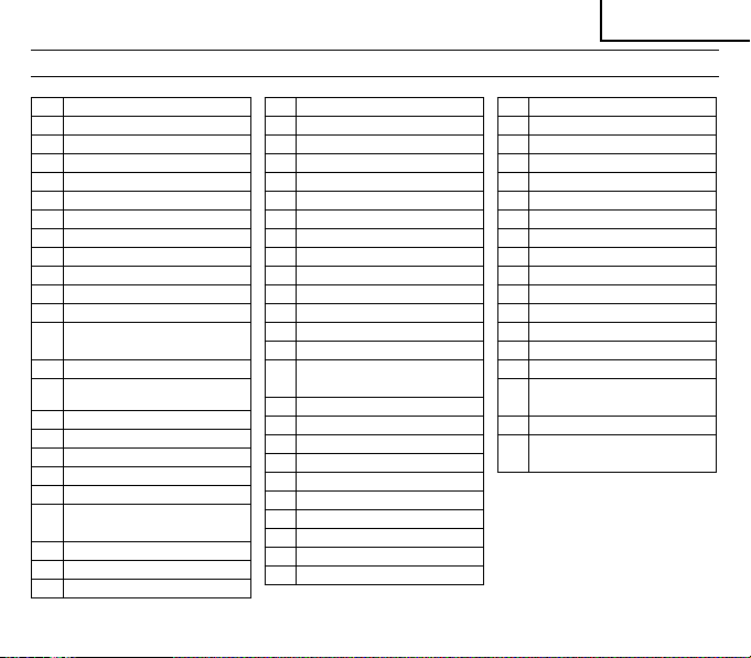
PARTS LIST ................................................................................... 47
Français
CONSIGNES DE SÉCURITÉ IMPORTANTES .........................19
SIGNIFICATION DES MOTS D’AVERTISSEMENT ...................19
SÉCURITÉ ..................................................................................... 19
AVERTISSEMENTS DE SÉCURITÉ GÉNÉRAUX
CONCERNANT LES OUTILS ÉLECTRIQUES .....................19
PRÉCAUTIONS RELATIVES AU TÉLÉMÈTRE LASER.............22
DESCRIPTION FONCTIONNELLE ............................................... 23
NOM DES PARTIES ...................................................................24
CARACTÉRISTIQUES TECHNIQUES .......................................25
ASSEMBLAGE ET FONCTIONNEMENT ...................................... 26
APPLICATIONS .........................................................................26
INSERTION/REMPLACEMENT DE LA PILE..............................26
UTILISATION DU TÉLÉMÈTRE LASER.....................................26
2
TABLE DES MATIÈRES
Page Page
ENTRETIEN ET INSPECTION ......................................................30
CONTRÔLE DE LA PRÉCISION (avant et après utilisation) ......30
STOCKAGE ...............................................................................31
MISE AU REBUT ........................................................................31
RÉPARATIONS .......................................................................... 31
ACCESSOIRES .............................................................................32
ACCESSOIRES STANDARD .....................................................32
ACCESSOIRES EN OPTION (vendus séparément)...................32
LISTE DES PIÈCES ....................................................................... 47
Page 3

Español
INSTRUCCIONES IMPORTANTES SOBRE SEGURIDAD ........33
SIGNIFICADO DE LAS PALABRAS DE SEÑALIZACIÓN ..........33
SEGURIDAD .................................................................................. 33
ADVERTENCIAS DE SEGURIDAD GENERAL DE LA
HERRAMIENTA ELÉCTRICA ................................................33
PRECAUCIONES PARA EL METRO DIGITAL LÁSER ..............36
DESCRIPCIÓN FUNCIONAL ........................................................ 37
NOMENCLATURA ..................................................................... 38
ESPECIFICACIONES ................................................................. 39
MONTAJE Y OPERACIÓN ............................................................40
APLICACIONES ........................................................................40
COLOCACIÓN O SUSTITUCIÓN DE LA BATERÍA ..................40
CÓMO UTILIZAR EL METRO DIGITAL LÁSER .........................40
ÍNDICE
Página Página
MANTENIMIENTO E INSPECCIÓN .............................................. 44
COMPROBACIÓN DE LA PRECISIÓN
(antes y después del uso del instrumento) .............................44
ALMACENAMIENTO .................................................................44
ELIMINACIÓN DE RESIDUOS ...................................................45
REPARACIONES ....................................................................... 45
ACCESORIOS ...............................................................................46
ACCESORIOS ESTÁNDAR .......................................................46
ACCESORIOS OPCIONALES (se venden por separado) ..........46
LISTA DE PIEZAS ......................................................................... 47
3
Page 4
123
1
6
3
4
5
2
8
9
0
m
a
!
@
7
#
$
%
^
(
*
&
e
t
)
q
z
w
r
y
4 5
p
a
s
(a) (b) (c)
p
a
i
d f g h j
o
678
k l ; z
x
v
v
c
4
b
c
b
n
Page 5
91011
m
v
.
4
∞
¢
/
,
12 13
∞
º
£
b
ª
¢
¶
•
¡
™
§
£
¡
§
fl
‡
‹
⁄
›
¤
fi
™
5
Page 6

English
IMPORTANT SAFETY INSTRUCTIONS
Read and u nderstand a ll of the safety preca utions, warn ings and operating instru ctions in the I nstructio n Manual befor e operating or maintaining
this power tool.
Most accidents that result from power tool operation and maintenance are caused by the failure to observe basic safety rules or precautions.
An accident can often be avoided by recognizing a potentially hazardous situation before it occurs, and by obser ving appropriate safety
procedures.
Basic safety precautions are outlined in the “SAFETY” section of this Instruction Manual and in the sections which contain the operation and
maintenance instructions.
Hazards that must be avoided to prevent bodily injur y or machine damage are identifi ed by WARNINGS on the power tool and in this Instruction
Manual.
NEVER use this power tool in a manner that has not been specifi cally recommended by HITACHI.
MEANINGS OF SIGNAL WORDS
WARNING indicates a potentially hazardous situations whic h, if ignored, could result in death or serious injur y.
CAUTION indicates a potentially hazardous situations which, if not avoided, may result in minor or moderate injur y, or may cause machine
damage.
NOTE emphasizes essential information.
SAFETY
GENERAL POWER TOOL SAFETY WARNINGS
WARNING
Read all safety warnings and all instructions.
Failure to follow the warn ings and instr uctions may re sult in e lectric shoc k, fi re and/o r serio us injury.
Save all warnings and instructions for future reference.
The term “ power tool” in t he warnings refers to your main s-op erated (corded) p ower too l or battery- operated (cord less) pow er tool.
6
Page 7

1) Wor k are a s af ety
a) Keep work area clean and well lit.
Clutt ered or dark area s invite a ccid ents.
b) Do not operate power tools in explosive atmospheres,
such as in the presence of fl ammable liquids, gases or
dust.
Power too ls create spark s which m ay igni te the du st or fumes.
c) Keep children and bystanders away while operating a
power tool.
Distractions can ca use you to l ose control.
2) Electrical safety
a) Power tool plugs must match the outlet.
Never modify the plug in any way.
Do not use any adapter plugs with earthed (grounded)
power tools.
Unmodifi ed plugs and matching outlets will reduce risk of
electric shock.
b) Avoid body contact with earthed or grounded sur faces,
such as pipes, radiators, ranges and refrigerators.
There is an increased risk of electric shock if your body is
earthed or grounded.
c) Do not expose power tools to rain or wet conditions.
Water enterin g a power tool wil l incre ase the r isk of electr ic
shock.
d) Do not abuse the cord. Never use the cord for carrying,
pulling or unplugging the power tool.
Keep cord away from heat, oil, sharp edges or moving
parts.
Damaged or entangled cords i ncrea se the ri sk of ele ctric
shock.
e) When operating a power tool outdoors, use an extension
cord suitable for outdoor use.
Us e of a cord s uitab le for outdoor use reduces the r isk of
electric shock.
f) If ope rating a pow er tool in a da mp locati on is unavoi dable,
use a residual current device (RCD) protected supply.
Use of an RC D reduc es the ri sk of ele ctric shock.
English
3) Personal safety
a) Stay alert, watch what you are doing and use common
sense when operating a power tool.
Do not use a power tool while you are tired or under the
infl uence of drugs, alcohol or medication.
A moment of inat tention while operat ing power tools m ay result
in serious per sonal injur y.
b) Use personal protective equipment. Always wear eye
protection.
Protective equipment such as dust mask, non-skid safety
shoes, hard hat, or hearing protection used for appropriate
conditions will reduce personal injuries.
c) Prevent unintentional star ting. Ensure the switch is in the
off -position before connecting to power source and/or
battery pack, picking up or carrying the tool.
Car rying powe r tools with yo ur fi nger on the switch or energising
power tools that have the sw itch on i nvites accid ents.
d) Remove any adjusting key or wrench before turning the
power tool on.
A wrench or a key left attached to a r otating part of the power
tool may re sult in personal inj ury.
e) Do not overreach. Keep proper footing and balance at all
times.
This en ables b etter control of the power tool in unexp ected
situations.
f) Dress properly. Do not wear loose clothing or jewellery.
Keep your hair, clothing and gloves away from moving
parts.
Loose clothes, jewellery or long hair can be caught in moving
parts.
g) If devices are provided for the connection of dust
extraction and collection facilities, ensure these are
connected and properly used.
Use of dust coll ectio n can red uce dust relat ed haza rds.
4) Power tool use and care
a) Do not force the power tool. Use the correct power tool
for your application.
7
Page 8

English
The co rrect power too l will do the job b etter and safe r at the rate
for whic h it was de signed.
b) Do not use the power tool if the switch does not turn it on
and off .
Any power tool that cannot be controlled with the switch is
dangerous and m ust be repaired .
c) Disconnect the plug from the power source and/or the
battery pack from the power tool before making any
adjustments, changing accessories, or storing power
tools.
Suc h preven tive sa fety mea sures r educe t he risk o f start ing the
power tool acci denta lly.
d) Store idle power tools out of the reach of children and do
not allow persons unfamiliar with the power tool or these
instructions to operate the power tool.
Power too ls are dangerou s in the hands of untrained user s.
e) Maintain power tools. Check for misalignment or binding
of moving parts, breakage of parts and any other
condition that may aff ect the power toolsʼ operation.
If damaged, have the power tool repaired before use.
Many acc ident s are cau sed by poorly mai ntained power tools.
f) Keep cutting tools sharp and clean.
Properly maintai ned cu tting tools with sharp cutting edges are
less li kely to bi nd and ar e easie r to cont rol.
g) Use the power tool, accessories and tool bits etc. in
accordance with these instructions, taking into account
the working conditions and the work to be performed.
Use of the power too l for operation s diff erent from those
intend ed could resu lt in a hazardou s situa tion.
5) Battery tool use and care
a) Use power tools only with specifi cally designated battery
packs.
Use of any other b atter y packs may crea te a risk o f injury and
fi re.
8
b) When battery pack is not in use, keep it away from other metal
objects like paper clips, coins, keys, nails, screws, or other
small metal objects that can make a connection from one
terminal to another.
Shorting the battery terminals together may c ause burns or a
fi re.
c) Under abusive conditions, liquid may be ejected from
the bat tery; avoid contact. If contact accidentally occurs,
fl ush with water. If liquid contacts eyes, additionally seek
medical help.
Liquid ejected from th e batte ry may c ause ir ritation or bu rns.
6) Service
a) Have your power tool serviced by a qualifi ed repair person
using only identical replacement parts.
This will ensu re that th e safet y of the po wer tool is maintained.
PRECAUTION
Keep children and infi rm persons away.
When not in use, tools should be stored out of reach of children
and infi rm persons.
Page 9

PRECAUTIONS FOR DIGITAL LASER METER
WARNING
1. Do not look directly at the laser beam through an optical
instrument.
Looking at the laser beam through a telescope, binoculars or
magnifying glass may damage your eyes.
2. If you feel the instrument is not working normally, do not under any
circumstan ces use it.
If the laser is too powerful or too weak, send the instrument for
repair.
3. Do not look directl y into the laser beam.
Looking directly into the laser beam may damage your eyes.
4. Avoid using the laser at eye level.
If the laser beam hits your eyes directly, it may damage your eyes.
5. Do not stand in the path of the laser beam.
6. Do not under any circumstances disassemble or modify the
instrument.
In the event of breakdown or repair, contact the dealer where you
purchased the instrument or your nearest Hitachi Koki power tool
service centre.
7. Do not place any refl ective object in the path of the laser beam.
If the laser beam is refl ected into your eyes, it may damage your
eyes.
8. If you suspect any injury due to the laser beam, consult a doctor
immediately.
9. Do not point the laser beam at anyone.
10. Do not allow the in strument to be used by a child.
CAUTION
1. Be sure to check the measuring acc uracy before and after use.
Using the instrument in a faulty condition may result in er ror.
2. Use the instrument in an ambient te mperature of 0°C to 40°C.
Use in any other environment may result in loss of accuracy or
failure to emit the laser beam.
3. Do not leave the instrument in the following places.
Doing so may result in loss of accuracy or breakdown.
English
○
Where it will be exposed to direct sunlight or high temperature
such as near a heating ap pliance
○
On the dashboard, in the trunk, on the luggage platform or in
direct sunlight inside a vehicle with the windows c losed
○
Wher e it will be exp osed to magn etism, vib ration, du st, moist ure
or humidity
4. Do not use the instrument if there is condensation on it.
Doing so may result in loss of accuracy or breakdown.
5. Do not use in a faulty condition.
Stop using the instrument immediately and contact the dealer
where it was purchased or your nearest Hitachi Koki power tool
service centre.
6. Do not subject the instrument to strong impact by dropping it or
knocking it over.
If dropped or knocked over, check the accu racy or send it for r epair.
7. Do not expose t he instrument to rain or water.
The performance or service life will be adversely aff ected and
malfunction may result.
8. Turn the power off before moving the instrument.
9. Do not touch the laser aper ture or receiver lens.
Doing so may result in loss of accuracy.
10. Place the instrument in the soft case for carrying.
Vibrat ion or impact may result in loss of accuracy or breakdown.
11. Store the instrument in the soft case.
Humidi ty or dust may cause breakdown.
12. Remove the battery when not in use.
Leakag e of battery fl uid may cause breakdown.
13. User safety trainin g
The user should have adequate understanding of the proper ties,
harmful eff ects, etc. of lasers.
14. Perform measuring in a safe place.
Disclaimer
○
Observe all safety warnings and instructions in this manual when
using the instrument.
Hitachi Koki assumes no responsibilit y for damages (including
losse s due to interr uption of bu siness) aris ing from use o f the produc t
other than in accorda nce with the instruc tions in the manual.
9
Page 10

English
○
Be sure to check the accuracy before and after use. Similarly,
check the accuracy af ter the instrument has been subjected to
impact by being knocked over or dropped. Hitachi Koki assumes
no responsibility for damages arising from error due to nonperformance of the accuracy check.
○
Hitachi Koki assumes no responsibility for damages arising from
use of the laser meter oth er than for the intended p urpose.
○
Hitachi Koki assumes no responsibility for damages arising from
fi re, earthquakes, fl oods, lightning and other disasters.
SAVE THESE INSTRUCTIONS
AND
MAKE THEM AVAILABLE TO OTHER USERS
AND
OWNERS OF THIS TOOL!
FUNCTIONAL DESCRIPTION
NOTE
The information contained in this Instruction Manual is des igned to assist you in the safe operation and maintenance of the power tool.
NEVER operate, or attempt any maintenance on the tool unless you have fi rst read and understood all safey instructions contained in this
manual.
Some illustrations in this Instruction Manual may show details or attachments that diff er from those on your own power tool.
10
Page 11
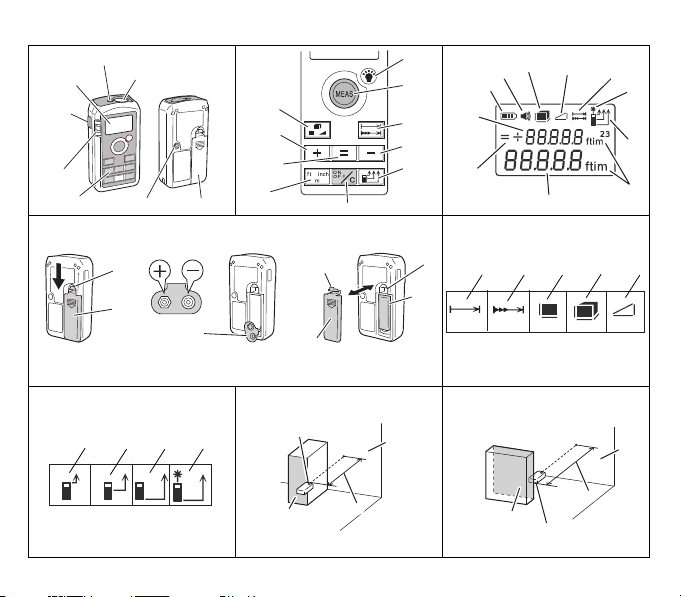
NAME OF PARTS
English
1
Laser a perture
2
Receiver lens
3
Side measure button
4
Bubble tube
5
Operation panel
6
Display
7
Measure button
8
Mode select button
9
Add button
0
Memory (beep) button
!
Unit select button
@
Display light button
Distance/Continuous measurement
#
button
$
Subtract button
Measuring reference point selec t
%
button
^
On/Off (Clear) but ton
&
Battery leve l indicator
*
Beep indicator
(
Area/Volume indicator
)
Side indicator
Distance/Continuous measurement
q
indicator
w
Measuring reference point indicator
e
Measurement/Result display
r
Measurement display
t
[=] [+] [–] indicator
y
Unit indicator
u
Digital laser meter
i
Hole
o
9 V alkaline bat tery
p
Hook
a
Battery cover
s
Connecting terminal
d
Distance indicator
f
Continuous measurement indicator
g
Area indicator
h
Volu me indi cator
j
Side indicator (Pythagoras’ theorem)
k
Front reference point indicator
W1/4 socket hol e reference point
l
indicator
;
Rear reference point indicator
z
Laser i ndicator
x
Instrument front (Reference point)
c
Target reference point
v
Tar ge t
b
Measured distance
n
Instrument rear (Reference point)
m
W1/4 socket hol e (Reference point)
,
Tripod
.
Bubble
/
Area
¡
Length
™
Lengthwise target
£
Instrument (placed lengthwise)
¢
Width
∞
Widthwise target
§
Instrument (placed widthwise)
¶
Volu me
•
Height
ª
Heightwise target
º
Instrument (placed heightwise)
⁄
Side C
¤
Side A
‹
Side B
›
Side A target
Instrument
fi
(placed lengthwise to side A)
fl
Side B target
Instrument
‡
(place d lengthwise to side B)
11
Page 12

English
SPECIFICATIONS
Power source 9 V alkaline bat tery (1)
Measuring modes Distance, continuous, area, volume, side
Measurable range *
Display unit Feet, inches and meter s
Laser
Measuring accuracy (repeated) *
Measuring time *
Minimum measurement unit 0.039˝ (1 mm)
Splash proof & dust-proof Protection Class IP5 4 *
Battery life Approx. 30,000 measurements *
Operating temperature range 0°C to 40°C
Storage temperature range –20°C to 6 0°C
Auto power off *
Dimensions (H × W × D) 4-3/8˝ × 2-9/32˝ × 1-17/64˝ (111 mm × 58 mm × 32 mm)
Weight 0.3 lbs (140 g) (including battery)
*1 The measurable range may var y depending on the characteristics of the laser beam refl ected from the target surface and the surrounding
brightness.
*2 Laser cla ss based on 21CFR part 1040.10.11
*3 The measuring accuracy may vary depending on the characteristics of the laser beam refl ected from the target surface and the surrounding
brightness.
*4 The measuring time may vary depending on the characteristics of the laser beam refl ected from the target surface and the surrounding
brightness.
*5 Water splashes and dust have no harmful eff ect.
*6 Bat tery life may be reduced depending on usage environment and type of bat tery.
*7 Time until the power turns off automatically when left unoperated.
12
1
4
7
3
Laser beam Approx. 3 0 sec.
Display Approx. 3 min.
1.64 ft to 164 ft (0.5 m to 50 m)
Laser: Visible light semiconductor laser 650 nm
Output: 1 mW or less (Class II *
2
)
±0.06˝ (±1.5 mm)
0.5 to 3 sec.
5
(excluding battery c ompartment)
6
Page 13
ASSEMBLY AND OPERATION
APPLICATIONS
○
Measuring distance, area, volume and side length at building sites
INSERTING/CHANGING THE BATTERY (See Fig. 4)
The battery i s not installed in the instrument when it leaves the factory.
Follow the instructions be low and insert the bat tery before use.
1. Pre ss the hook of the battery cove r in the direction of the arrow and
remove the battery cover. (a)
2. Connect a new battery, paying attention to the correct polarity. (b)
3. Insert t he battery wi th the termina l at the bottom. M atch the hook to
the hole in the main unit a nd press the bat tery cover shut. (c)
HOW TO USE THE DIGITAL LASER METER
Operation
WARNING
Never look directly into the laser beam or point the beam at
anyone.
If the light gets in your eyes, it may damage your eyes.
1. Turn on the power (Fig. 1, 2)
○
Press the power on/off (clear) button on the operation panel,
and when the power is turned on, the display appears.
○
To t urn off the power, press and hold the power on/off (clear)
button for at least 2 sec onds.
2. Select a measuring mode (Fig. 2, 5)
○
There are fi ve measuring modes to choose from: distance,
continuous, area, volume and side. Select a mode by pressing
the distance/continuous measu rement selec t button and mo de
select button on the operation panel. The selected mode is
indicated on the display.
English
○
The default setting is the distance mode. You can change the
selected mode or measure in the selected mode for as long as
the power is on.
3. Select a unit (Fig. 2, 3)
Press t he unit selec t button on the o peration pan el. There are th ree
units to choose from: feet, inches and meters. The selected unit is
indicated on the display.
4. Select a reference point (Fig. 2, 6)
○
There are three reference settings to choose from: front, W1/4
socket hole and rear.
○
Select a reference point by pressing the Measuring reference
point select button. The selected reference point is indicated
on the display.
○
When the power is turned on, the last reference point that was
set is selected. If necessary, select a diff erent reference point.
Examples of measuring using diff erent reference points
1
Measuring using front reference point (Fig. 7)
Place the front (reference point) of the instrument against the
measuring surface.
2
Measuring using rear reference p oint (Fig. 8)
Place the rear (reference point) of the instrument against the
measuring surface.
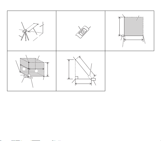
3
Measuring using the W1/4 socket hole (for the tripod) as the
reference point (Fig. 9)
Use the center of the socket hole for at taching the tripod as the
reference point.
NOTE
If the instrument needs to be level with the target, adjust the level
using the bubble tube. (Fig. 10)
13
Page 14

English
5. Measuring procedures in each mode
NOTE
○
Check that there is nothing obstructing measurement by the laser.
○
Do not move the instrument during measuring (except during
continuous measurement).
○
The center of the laser beam is measured. The same applies when
the beam is aimed diagonally at the target.
○
The meas uring range m ay vary depen ding on the cha racterist ics of
the laser beam refl ected from the target surface or the surrounding
brightness.
To measure quickly and accurately outdoors in bright sunlight, use
a target plate (sold separately) or put the target in the shade.
○
Measuring errors may occur with transparent surfaces (such as
gla ss or wat er) or mi rror su rface s, as we ll as in t he case of surf aces
with ho les in, uneve n surfac es, diff erent temperatures and indirectly
refl ected light.
○
If the power is turned on and no button is pressed, the power will
turn off automatically after approximately 3 minutes. Press the
power button ag ain to resume operation.
○
If the instrument is used and then left with no button pressed,
the laser will turn off after approximately 30 seconds. Press the
measure button again to resume operation.
○
The length of time after the power is turned on until the instrument is
ready to measure may vary depending on the usage environment.
○
If an error occurs while measuring, remedy the cause before
resuming measuring.
Measuring distance (Fig. 2, 6)
1
Select distance m ode. (See “Selecting a m easuring mode”)
2
P ress the meas ure button an d aim the lase r beam at the tar get. The
status is indicated on the display.
3
Pres s the measure button a gain to stop measuring. A beep sounds
and the measur ement is indic ated on the display. When measuri ng
is fi nished, the laser g oes off .
4
To continue measuring distance, repeat steps 2 and 3.
The si de button on th e side of the ins trument has t he same funct ion
as the measure button on the op eration panel.
14
For convenient operation in narrow spaces, the instrument can be
placed in a vertical position.
Continuous measurement
Use continuous measurement to set the desired position from the
target.
1
Select continuous measurement mode. (See “Selecting a
measuring mode”)
2
Press the mea sure button and aim the laser beam at the target.
3
Move th e instrument until the desired mea surement is in dicated on
the display.
4
Pr ess the meas ure button ag ain to fi nish continuous measurement.
The last measurement is indicated on the display.
Measurements are successively indicated on the display with a beep
sound every 0.5 to 3 seconds.
The previous measurement is deleted when the next measurement is
taken.
In continuous measurement mode, the power does not turn off
automatically. Be sure to press the power button after operation to end
continuous measurement.
Measuring area (Fig. 11)
If you measure the length and the width, the area is automatically
calculated.
1
Select area mode. (See “Selecting a measuring mode”)
2
Measure the l ength.
○
Press the measure button and aim the laser at the target
length.
○
Press the measure button again to fi nish measuring. A beep
sounds and the length measurement is indicated on the
display. The laser does not go off at this time.
3
Measure the width.
○
Press the measure button and aim the laser at the target width.
○
Press the measure button again to fi nish measuring. A beep
sounds and the width measurement and calculated area are
indicated on the display.
Page 15
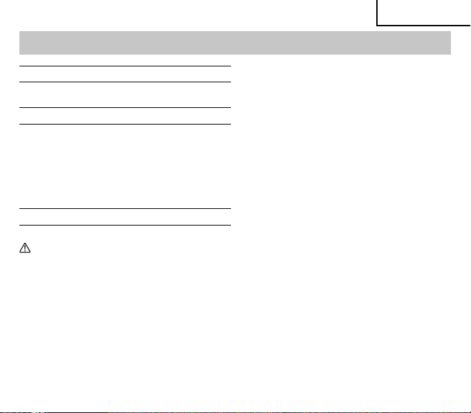
Display Content
Before measuring ----- ft
After measur ing
length
After measur ing
width
Measuring volume (Fig. 12)
If you mea sure the len gth, width an d height, the v olume is auto matically
calculated.
1
Select volume mode. (See “Selecting a mea suring mode” )
2
Measure the l ength.
Follow the instructions for measuring the length in area mode.
3
Measure the width.
Follow the instructions for measuring the width in area mode.
4
Measure the h eight.
○
Press the measure button and aim the laser at the target
height.
○
Press the measure button again to fi nish measuring. A beep
sounds and the height measurement and calculated volume
are indicated o n the display.
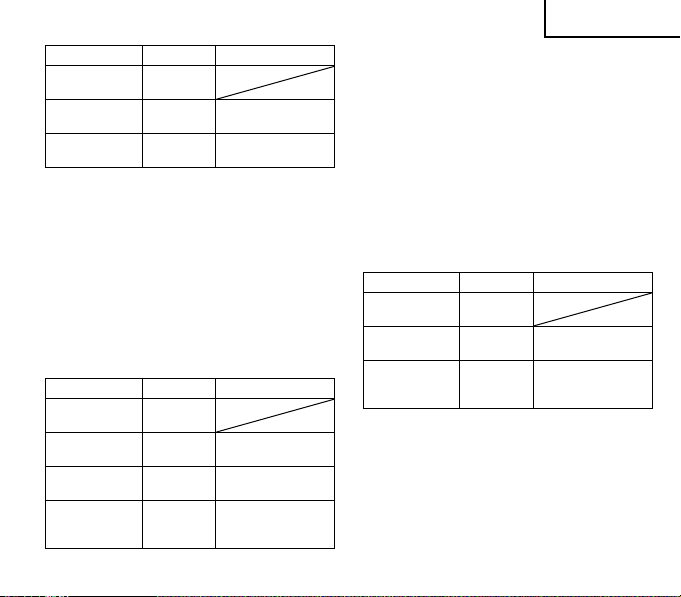
Before measuring ----- ft
After measur ing
length
After measur ing
width
After measur ing
height
2
----- ft
3.083 ft
→Length measurement
3.083 ft
→Length measurement
2
6.289 ft
→Area calculation result
2.040 ft
→Width measurement
Display Content
3
----- ft
3.083 ft
→Length measurement
3.083 ft
→Length measurement
2
2.040 ft
0.848 ft
3
→Area calculation result
→Width measurement
→ Volume calculation
result
→Height measurement
6.289 ft
5.333 ft
English
Measuring sides (Pythagorean theorem)
If you measure the two sides of a right triangle, the length of the third
side is calculated automatically.
Use thi s mode when you c annot measu re the distan ce because t here is
an obstacle or there is n o elevated target surface.
To obtain side C (Fig. 13)
1
Select side mode. (See “Selecting a measuring mode”)
2
Measure the l ength of side A.
Follow the instructions for measuring the length in area mode and
measure side A .
3
Measure side B.
○
Follow the instructions for measuring the length of side A and
measure the length of s ide B.
○
When you have fi nished measuring, a beep sounds and the
measured length of side B and calculated result of side C are
indicated on the display.
Before measuring ----- ft
After measur ing
side A
After measur ing
side B
Display Content
----- ft
1.862 f t
→Side A measurement
1.862 f t
→Side A measurement
5.039 ft
→ Calculated result of
5.372 ft
side C
→Side B measurement
15
Page 16

English
Deleting a measurement (Fig. 2)
Press the power on/off (clear) button on the operation panel to delete
a measurement.
Turning on the display light (Fig. 2)
Press the display light button to turn the gre en backlight on and off .
The backlight goes off automatically after approximately 8 seconds if
no button is pressed.
The backlight cannot be turned on and off while measuring.
Muting the beep (Fig. 2)
Press and hold the memory button on the operation panel for at least 2
seconds to turn the bee p on and off .
Changing the unit (Fig. 2)
Press the unit select button on the operation panel to change the
measurement unit.
Turning off the power (Fig. 2)
Press and hold the power on/off (clear) button on the operation panel
for at least 2 seconds to turn the power off .
6. Saving, adding, subtracting and deleting a measurement
Saving (Fig. 2, 3)
Press the memory button to save the measurement indicated on
the display. [=] appears in the top row of the display and the saved
measurement is indicated next to it.
The saved measurement is not deleted when the power is turned off
and it is indicated in the top row of the display the next time the power
is turned on.
Adding (Fig. 2, 3)
A new measurement can b e added to a previo us measureme nt already
stored in the memory.
Press t he add butto n when a measu rement is dis played. The ca lculated
result and [+] next to it blink 3 t imes in the top row on the display.
Measurements in diff erent units (ft, ft
16
2
, ft3) cannot be added.
Subtracting (Fig. 2, 3)
A new measurement can be subtracted from a measurement already
stored in the memory.
Press the subtract button when a measurement is displayed. The
calculated result and [–] nex t to it blink 3 times in the top row on the
display.
Measurements in diff erent units (ft, ft
NOTE
○
You can continue adding or subtracting when a measurement is
indicated on the display.
○
Press ing the memor y button wh en a measure ment is alrea dy saved
in the memory a nd the latest measurement is shown on the display
deletes the existing measurement.
Deleting a saved measurement (Fig. 2, 3)
1
Press the memory button to move the measurement indicated on
the display to the top row.
2
Press the power on/off (clear) button to delete the memory.
2
, ft3) cannot be subtracted.
Page 17

MAINTENANCE AND INSPECTION
English
CHECKING THE ACCURACY (before and after
use)
If the accuracy is found to be faulty, contact the d ealer for repairs.
WARNING
Be sure to check the following before and after use.
Using the instrument in a faulty condition may lead to errors.
Checking repeated measuring accuracy
1
Fix the position of the instrument and measure a distance of
approximately 3 ft (1 m) to 16 ft (5 m) ten times.
2 Accuracy is normal if the variation in the measurements is within
0.12˝ (3 mm).
Measuring accuracy may vary depending on the characteristics of
the laser beam refl ected from the target surface or the surrounding
brightness. Measure the target surface under the following conditions.
○
Dark place away from direct sunlight
○
Smooth surface
○
Not too strongly refl ectin g surface (mirror, etc.)
○
White or gray wall
○
Free from steam, mirage or dust
Causes of error and remedies
Error
code
201
202
203
Cause Remedy
Outside measuring
range
Refl ected signal is
too weak
Exceeded display
range
Use within measuring range.
Measure target surface in
good condition.
Press on/off button to reset.
Calculation error
204
(Pythagorean theorem)
205 Exhausted battery Replace with new battery.
206 Temperature too high Use in ra nge of 0oC to 40o C.
207 Temperature too low Use in range of 0oC to 40oC.
Surroundings too
208
bright
Measure in correct order.
Measure away from strong
light (direct sunlight, etc.).
STORING
○
After use, be sure to turn off the power and store the instrument in
the provided case.
○
If the instrument is not to be used for a long period, remove the
battery.
○
Avoid stor ing the unused i nstrument o r accessori es in the followi ng
places. Store in a safe, dr y place.
NOTE
○
Keep out of reach of children
○
Keep out of the rain, such as under the eaves, and away from
humidity
○
Store out of direct sunlight
○
Store away from rapid chang es in temperatu re
○
Store away from vibration
DISPOSAL
Dispose of the instrument appropriately by a method specifi ed by the
local government of the area.
Disposing of the instrument inappropriately may result in the following
problems.
17
Page 18

English
○
Burning plastic components generates noxious fumes that may
present a danger to public health.
○
If the battery is damaged or is heated and explodes, it may lead
to poisoning, burns, corrosion or fi re or cause environmental
pollution.
○
Disp osing of the i nstrumen t irrespon sibly may le ad to someone w ith
no knowledge of the product using it in violation of the regulations.
This may lead to serious injury not only to yourself but to others, as
well as causing enviro nmental pollution.
Disposal of battery
Do not dispose of the used battery with household garbage or throw
into fi re or water. Dispose of it in a legally defi ned and environmentally
friendly manner.
REPAIRS
This product is a high-precision instrument. If it does not operate
normally, do not at tempt to repair it yourself. Contact the dealer.
ACCESSORIES
WARNING
ALWAYS use Only authorized HITACHI replacement parts and accessories. NEVER use replacement parts or accessories which
are not intended for use with this tool. Contact HITACHI if you are not sure whether it is safe to use a particular replacement part
or accessory with your tool.
The use of any other attachment or accessory can be dangerous and could cause injury or mechanical damage.
NOTE
Accessories are subject to change witho ut any obligation on the part of the HITACHI.
STANDARD ACCESSORIES
○
Soft case ..........................................................................................1
○ 9 V alkaline batter y .......................................................................... 1
○ Strap ................................................................................................1
18
OPTIONAL ACCESSORIES (sold separately)
○
Tar get plate
NOTE
Due to HITACHI’s continuing program of research and development,
the specifi cations herein are subject to change without prior notice.
Page 19

Français
CONSIGNES DE SÉCURITÉ IMPORTANTES
Lire et comprendre toutes les précautions de sécurité, les avertissements et les instructions de fonctionnement dans ce mode d’emploi avant
d’utiliser ou d’entretenir cet outil motorisé.
La plup art des acc idents caus és lors de l’ut ilisation o u de l’entretie n de l’outil motor isé provien nent d’un non re spect des rè gles ou précautions de
base de sécurité. Un accident peut la plupart du temps être évité si l’on reconnaît une situation de danger potentiel avant qu’elle ne se produise,
et en observant les procédures de sécurité appropriées.
Les précautions de base de sécurité sont mises en évidence dans la section “SÉCURITÉ” de ce mode d’emploi et dans les sections qui
contiennent les instructions de fonctionnement et d’entretien.
Les dangers qui doivent être évités pour prévenir des blessures corporelles ou un endommagement de la machine sont identifi és par
AVERTISSEMENTS sur l ’outil motorisé et dans ce mode d’emploi.
NE JAMAIS utiliser cet outil motorisé d’une manière q ui n’est pas spécifi quement recommandée par HITACHI.
SIGNIFICATION DES MOTS D’AVERTISSEMENT
AVERTISSEMENT indique des situations potentiellement dangereuses qui, si elles sont ignorées, pourraient entraîner la mort ou de sérieuses
blessures.
PRECAUTION indique des situations dangereuses potentilles qui, si elles ne sont pas évitées, peuvent entraîner de mineures et légères
blessures ou endommager la machine.
REMARQUE met en relief des i nformations essentielles.
SÉCURITÉ
AVERTISSEMENTS DE SÉCURITÉ GÉNÉRAUX CONCERNANT LES OUTILS ÉLECTRIQUES
AVERTISSEMENT
Lire tous les avertissements de sécurité et toutes les instructions.
Tout manque ment à ob server ces ave rtis sements et instructions p eut eng endre r des cho cs éle ctriq ues, des ince ndies et/ou de s blessures
graves.
Conservez tous les avertissements et toutes les instructions pour vous y référer ultérieurement.
Le terme "o util él ectrique", ut ilisé dans le s avertissem ents, s e réfère aux outils élec triqu es (câblé) ou aux outils à pil es (sans fi l).
19
Page 20

Français
1) Sécurité sur l'aire de travail
a) Maintenir l'aire de travail propre et bien éclairée.
Les endr oits en combrés ou sombres sont prop ices aux
accidents.
b) Ne pas utiliser d'outils électriques en présence de
liquides, gaz ou poussière infl ammables, au risque de
provoquer une explosion.
Les outi ls électriques créent des étince lles suscep tibles
d'enfl ammer la poussi ère ou le s vapeurs.
c) Ne pas laisser les enfants et les visiteurs s'approcher de
vous lorsque vous utiliser un outil électrique.
Les dist racti ons peu vent fai re perd re le contrôle.
2) Sécurité électrique
a) Les prises de l'outil électrique doivent correspondre à la
prise secteur.
Ne jamais modifi er la prise.
Ne pas utiliser d'adaptateurs avec les outils électriques
mis à la masse.
L es prise s non mod ifi ée s et les pri ses sec teurs co rrespo ndante s
réduis ent les risque s de choc élect rique.
b) Eviter tout contact avec les surfaces mises à la masse
telles que les tuyaux, radiateurs, bandes et réfrigérateurs.
Le risq ue de choc élec triqu e est accru en ca s de mise à l a
masse du corps .
c) Ne pas exposer les outils électriques à la pluie ou à des
conditions humides.
Si l'eau pénètre dans l'outil, cela au gmente les ris ques de choc
électrique.
d) Ne pas utiliser le cordon à tort. Ne jamais utiliser le
cordon pour transporter ou débrancher l'outil électrique.
Maintenir le cordon loin de la chaleur, de l'huile, des
bords pointus ou des pièces mobiles.
Les cordo ns endo mmagés ou usé s augme ntent les risq ues de
choc électrique.
e) En cas d'utilisation d'un outil électrique à l'extérieur,
utiliser un cordon de rallonge adapté à un usage
extérieur.
20
L'utilis ation d 'un co rdon adapté à l'usage ex térieur réduit les
risques de cho c électrique.
f) Si vous devez utiliser un outil électrique dans un endroit
humide, utilisez une alimentation protégée contre les
courants résiduels.
L'utilisation d'un dispositif de protection contre les courants
résiduels réd uit le ri sque de choc éle ctrique.
3) Sécurité personnelle
a) R este z al ert e, re gar der c e que vo us fai tes e t use z de vo tre
bon sens en utilisant un outil électrique.
Ne pas utiliser d'outil électrique si vous êtes sous
l'infl uence de drogues, d'alcool ou de médicaments.
Pendant l'utili satio n d'out ils éle ctrique, un instant d 'inattent ion
peut entraîner d es blessures graves.
b) Utiliser un équipement de protection individuelle.
Toujours porter des verres de protection.
L'utili sation d'équ ipeme nts de pr otection tels que les m asque s
anti-poussière, les chaussures de sécurité anti-dérapantes,
les casques ou l es protectio ns audi tives dans des c ondit ions
approp riées réduisent les risque s de blessures.
c) Empêcher les démarrages intempestifs. Veiller à ce que
l'interrupteur soit en position d'arrêt avant de brancher à
une sou rce d'alimen tation et /ou une batte rie, de rama sser
l'outil au sol ou de le transporter.
Transpor ter les outil s électriqu es avec le doigt su r l'interru pteur
ou brancher les outils électriques avec l'interrupteur en position
de marche peut entraîner des accidents.
d) Retirer toute clé de sécurité ou clé avant de mettre l'outil
électrique en marche.
Laisse r une clé ou une cl é de sécurité su r une partie mobile d e
l'outi l électrique p eut eng endrer des blessure s.
e) Ne pas trop se pencher. Toujours garder une bonne
assise et un bon équilibre pendant le travail.
Cela permet un meilleur contrôle de l'outil électrique dans des
situations imprévisibles.
Page 21

f) Porter des vêtements adéquats. Ne pas porter de
vêteme nts amples ni de bijoux. Maintenir les cheveux, les
vêtements et les gants loin des pièces mobiles.
Les vêtements amples ou les cheve ux long s peuvent se
prendre dans le s pièces mobi les.
g) En cas de dispositifs destinés au raccordement
d'installations d'extraction et de recueil de la poussière,
veiller à ce qu'ils soient correctement raccordés et utilisés.
L'utilisation d'un dispositif de collecte de la poussière peut
réduire les dan gers as sociés à la poussière.
4) Utilisation et entretien d'un outil électrique
a) Ne pas forcer sur l'outil électrique. Utiliser l'outil
électrique adapté à vos travaux.
Le bon outil élect rique fera le travail mie ux et en toute séc urité
au régime pour lequel i l a été con çu.
b) Ne pas utiliser l'outil électrique si l'interrupteur ne le met
pas en position de marche et d'arrêt.
Tout outil ne pouvant être contrôlé par l'interrupteur est
dangereux et do it être ré paré.
c) Débrancher la prise et/ou la batterie avant de procéder
à des réglages, au remplacement des accessoires ou au
stockage des outils électriques.
Ces mesure s préventives de sécuri té réduisent l es risq ues de
démarrage accidentel de l'o util électri que.
d) Stockez les outils électriques inutilisés hors de la
portée des enfants et ne pas laisser des personnes non
familiaris ées avec l'outil ou ces i nstructio ns utiliser l'outil
électrique.
Les o utils électrique s sont da ngereux entre l es main s
d'utilisateurs non habilités.
e) Entretenir les outils électriques. Vérifi er l'absence de
mauvais alignement ou d'arrêt, d'endommagement de
pièces ou toute autre condition susceptible d'aff ecter
l'opération de l'outil.
Si l'outil est endommagé, le faire réparer avant
utilisation.
De nomb reux acciden ts sont d us à des ou tils mal entre tenus .
Français
f) Maintenir les outils coupants aiguisés et propres.
D es outils cou pants b ien ent retenu s avec des bords aiguis és
sont moins susceptibles de se coincer et plus simples à
contrôler.
g) Utiliser l'outil électrique, les accessoires et les mèches
de l'outil, etc. conformément à ces instructions en tenant
compte des conditions d'utilisation et du travail à réaliser.
L'utilisation de l'outil électrique pour des opérations diff érentes
de cell es pour l esquelles i l a été con çu est dangere use.
5) Utilisation et entretien de l’outil à batterie
a) Utiliser les outils électriques exclusivement avec les
batteries désignées.
L’utilisation d’autres batteries peut ent raîner u n risqu e de
bless ures et d ’incendie.
b) Lorsque la batterie n’est pas utilisée la garder à l’écart
d’objets métalliques tels que trombones, pièces, clés,
clous, vis ou autres petits objets métalliques pouvant
interférer avec les bornes de la batterie.
L’interférence avec les bornes de la batterie peut entraîner des
brûlures ou un incendie.
c) Dans des conditions extrêmes, du liquide peut couler
de la batterie ; éviter tout contact. En cas de contact
accid entel, rinc er à l’eau. En cas de c ontact avec le s yeux,
consulter un médecin.
Le liquide de la batterie peut entraîner des irritations ou des
brûlures.
6) Service
a) Faire entretenir l'outil électrique par un technicien habilité
à l'aide de pièces de rechange identiques exclusivement.
Cela garantir a le main tien de l a sécurité de l'outil élect rique.
PRECAUTIONS
Maintenir les enfants et les personnes infi rmes éloignés.
Lorsque les outils ne sont pas utilisés, ils doivent être rangés
hors de portée des enfants et des personnes infi rmes.
21
Page 22

Français
PRÉCAUTIONS RELATIVES AU TÉLÉMÈTRE
LASER
AVERTISSEMENT
1. Ne regardez jamais directement le faisceau laser à travers un
instrument optique.
’
obser vation du fa isceau la ser à travers u n téléscop e, des jumell es
L
ou une loupe peut entraîner des s équelles oculaires.
2. Si vous pensez que l
’
utilisez en aucun cas.
ne l
Si le l aser est trop p uissant ou t rop faible, fa ites répare r l
en atelier.
3. Ne regardez jamais direc tement le faisceau laser.
En fi xant directement un faisceau laser, vous exposez vos yeux à
un risque de lésion permanente.
4. Évitez d
Ris que de lé sion oc ulair e en cas de con tact di rect de s yeux ave c le
faisceau laser.
5. Ne restez pas sur la trajectoire du faisceau laser.
6. Ne tentez en aucun cas de démonter l
modifi er.
En ca s de panne ou si u ne réparati on s
le revendeur auprès duquel vous avez acheté l
centre d
7. Ne placez aucun objet réfl échissant sur la trajectoire du faisceau
laser.
La réfl exion du faisceau laser vers vos yeux peut entraîner des
séquelles permanentes.
8. Si vous pensez avoir été blessé par un rayon laser, consultez
immédiatement un médecin.
9. Ne pointez pas le fais ceau laser vers une autre personne.
’
instrument ne doit en aucun cas être utilisé par un enfant.
10. L
PRÉCAUTION
1. Vér ifi ez la précision de la mesure avant et après chaque
utilisation.
22
’
instrument ne fonctionne pas normalement,
’
instrument
’
utiliser le laser au ni veau des yeux.
’
instrument ou de le
’
avère né cessaire, c ontactez
’
’
entretien Hitachi Koki le plus proche de votre domicile.
instrument, ou le
’
anomalie, l’utilisation de l’instrument peut entraîner une
En cas d
erreur de mesure.
’
instrument doit être utilisé à une température ambiante comprise
2. L
entre 0°C et 40°C.
Toute utilisation dans un autre environnement peut entraîner une
diminution de la précision ou empêcher la transmission du faisceau
laser.
3. Ne stockez pas l
Sa précision pourrait s
panne.
○
Tout endroit exposé à la lumière directe du soleil ou à une
○
Sur le tableau de bord, dans le coff re, sur la plage-arrière d’un
○
Tout endro it exposé à un ch amp magnéti que, des vib rations, de
’
utilisez pas l’instrument s’il est recouvert de condensation.
4. N
Sa précision pourrait s
panne.
’
utilisez pas l’instrument s’il présente une anomalie.
5. N
Ar rêtez immé diatement t oute utili sation de l
le revendeur ou du centre d
votre domicile.
6. Ne laissez pas tomber l
chocs.
En cas de chu te ou de choc v iolent, v érifi ez la précision de l
ou faites-le réparer.
’
exposez pas l’instrument à la pluie o u à l’eau.
7. N
Les p erforman ces de l
aff ectées et l
8. Coupez l
9. Ne touchez pas l
La préc ision de l
10. Placez l
Les vibrations ou les impacts pourraient entraîner une perte de
précision ou une pann e.
’
instrument dans les e ndroits suivants.
’
en trouver altérer ou il pourrait tomber en
température élevée (à proximité d’un appareil de chauff age)
véhicule ou tout autre endroit exposé à la lumière directe du
’
un véhicule aux v itres fermées
soleil d
’
la poussière ou de l
’
alimentation avant de déplacer l’instrument.
’
instrument dans son b oîtier souple pour le transporter.
humidité
’
en trouver altérée ou il pourrait tomber en
’
’
entretien Hitachi Koki le plus proche de
’
appareil et ne le soumettez pas à des
’
appare il ou sa durée d e vie s’en trouveraient
’
appareil pourrait présenter un dysfonctionnement.
’
orifi ce du faisceau laser ni la lentille du récepteur.
’
instrument pourrait s’en trouver altérée.
instrument et contactez
’
appareil
Page 23

Français
11. Stockez l’instrument dans son b oîtier souple.
’
humidité ou la poussière risquent de provoquer une panne.
L
12. Ôtez la batterie quan d vous n
Une fuite du liquide de batterie risque d
13. Formation à la sécurité
’
utilisateur doit être mis au courant des propriétés des faiseaux
L
lasers et de leurs eff ets nocifs.
14. Réalisez les mesures dans un endroit sécurisé.
Clause de non responsabilité
○
Observez tous les avertissements et instructions de sécurité
présentés dans ce manuel lor sque vous utili sez l
Hitachi Koki dégage toute responsabilité en cas de détérioration
(y compris en cas de per tes dues à une interruption de l
’
une utilisation du produit contraire aux instructions du
découlant d
présent manuel.
’
utilisez pas l’instrument.
’
entraîner une panne.
’
instrument.
○
Véri fi ez la précision de la mesur e avant et après chaque utilisation.
De même, vérifi ez la précision de l
’
il a été soumis à un impact. Hitachi Koki se dégage de toute
s
responsabilité en cas de détérioration découlant d
’
absence de contrôle d e la précision.
à l
○
Hitachi Koki se dégage de toute responsabilité en cas de
détérioration découlant d
’
usage pour lequel il a été prévu.
l
○
Hitachi Koki se dégage de toute responsabilité en cas de
détérioration découlant d
’
une inondation, d’un orage ou d’une catastrophe naturelle d’un
d
’
activité)
autre t ype.
’
instrument s’il est tombé ou
’
une utilisation du télémètre contraire à
’
un incendie, d’un tremblement de terre,
’
une erreur due
CONSERVER CES INSTRUCTIONS
ET
LES METTRE A LA DISPOSITION DES AUTRES UTILISATEURS
ET
PROPRIETAIRES DE CET OUTIL!
DESCRIPTION FONCTIONNELLE
REMARQUE
Les informations contenues dans ce mode d’emploi sont conçues pour assister l’utilisateur dans une utilisation sans danger et un entretien
de l’outil motorisé.
NE JAMAIS utiliser ni entreprendre une révision de l ’outil sans avoir d’abord l u et compris toutes les instru ctions de sécurité c ontenues dans
ce manuel.
Certaines illustrations dans ce mode d’emploi peuvent montrer des détails ou des accessoires diff érents de ceux de l’outil motorisé utilisé.
23
Page 24

Français
NOM DES PARTIES
1
Orifi ce du fais ceau laser
2
Lentille du récepteur
3
Bouton de mesure du côté
4
Tube à bulle
5
Panneau de comm ande
6
Affi chage
7
Bouton Mesurer
8
Bouton de sélection du mode
9
Bouton Ajouter
0
Bouton Mémoire (bip)
!
Bouton de sélection de l’unité
@
Bouton de lumière de l’affi chage
Bouton de mesure de la distance/
#
mesure continue
$
Bouton Soustraire
Bouton de sélection du point de
%
référence de la mesure
^
Bouton Marche/Arrêt (Eff acer)
&
Indicateur de n iveau de la batterie
*
Indicateur sonore
Indicateur de la superfi cie/du
(
volume
)
Indicateur latéral
Indicateur de mesure de la distance/
q
mesure continue
Indicateur du p oint de référence de
w
la mesure
e
Affi chage de la mesure/du résultat
24
r
Affi chage de la mesure
t
[=] [+] [–] indicateur
y
Indicateur de l’unité
u
Télémètre laser
i
Orifi ce
o
Batterie alcaline 9 V
p
Crochet
a
Couvercle de la batterie
s
Borne de branchement
d
Indicateur de distance
f
Indicateur de mesure continue
g
Indicateur de la superfi cie
h
Indicateur du volume
Indicateur du côté (Théorème de
j
Pythagore)
Indicateur du p oint de référence
k
avant
Indicateur du p oint de référence de
l
’
orifi ce de la douille W1/4
l
Indicateur du p oint de référence
;
arrière
z
Indicateur laser
Avant de l’instrument (point de
x
référence)
c
Point de référence cible
v
Cible
b
Distance mesurée
Arrière de l’instrument (point de
n
référence)
Orifi ce de la douille W1/4 (point de
m
référence)
,
Tré pi ed
.
Bulle
/
Superfi cie
¡
Longueur
™
Cible dans le sens de la longueur
Instrument (placé dans le sens de
£
la longueur)
¢
Largeur
∞
Cible dans le sens de la largeur
Instrument (placé dans le sens de
§
la largeur)
¶
Volu me
•
Hauteur
ª
Cible dans le sens de la hauteur
Instrument (placé dans le sens de
º
la hauteur)
⁄
Côté C
¤
Côté A
‹
Côté B
›
Côté A cible
Instrument
fi
(placé dans le sens de la longueur
par rapport au côté A)
fl
Côté B cible
Instrument
‡
(placé dans le sens de la longueur
par rapport au côté B)
Page 25

Français
CARACTÉRISTIQUES TECHNIQUES
Source d´aliment ation Batterie alcaline 9 V (1)
Modes de mesure Distance, continue, superfi cie, volume, côté
Plage de m esure *
Unité d
Laser
Précision de la mesure (répétée) *
Durée de la mesure *
Unité de mesure m inimum 0.039˝ (1 mm)
Résistant aux éclaboussures et résistant à la
poussière
Durée de vie de la batter ie Environ 30,000 mesures *
Plage de tempér atures d’utilisation 0°C à 40°C
Plage de tempér atures de stockage –20°C à 60°C
Extinction
automatique *
Dimensions (L × H × P) 4-3/8˝ × 2-9/32˝ × 1-17/64˝ (111 mm × 58 mm × 32 mm)
Poids 0.3 livres (140 g) (avec batterie)
*1 La plage de mesures peut dépendre des caractéristiques du faisceau laser réfl échi à partir de la surface ciblée et de la luminosité de
’
environnement.
l
*2 Classe de laser basée sur l a 21CFR partie 1040.10.11
*3 La précision de la mesure peut dépendre des caractéristiques du faisceau laser réfl échi à partir de la surface ciblée et de la luminosité de
l’environnement.
*4 La durée de la mesure peut dépendre des caractéristiques du faisceau laser réfl échi à partir de la surface ciblée et de la luminosité de
’
environnement.
l
*5 Les éclaboussures d
*6 La durée de vie de la batterie dépend de l
*7 Délai avant extinction automatique en cas de non-utilisation.
1
’
affi chage Pieds, pouces et mètres
3
4
1.64 ft à 164 ft (0.5 m à 50 m)
Laser : L aser semi-condu cteur à lumière visible 650 nm
Puissance : 1 mW maximum (Classe II *
±0.06˝ (±1.5 mm)
de 0.5 à 3 sec.
Classe de prote ction IP54 *
Faisceau laser Environ 30 sec.
7
Affi chage Environ 3 min.
’
eau et la poussière ne nuisent pas au fonctionnement de l’appare il.
’
environnement d’utilisation et du type de batterie.
2
)
5
(à l’exception du compartiment de la bat terie)
6
25
Page 26

Français
ASSEMBLAGE ET FONCTIONNEMENT
APPLICATIONS
○
Mes ure de la dis tanc e, de l a sup erfi cie , du vol ume e t du cô té laté ral
sur des sites de construction
INSERTION/REMPLACEMENT DE LA PILE (Voir
Fig. 4)
À la sortie de l’usine, la batterie n’est pas installée dans l’instrument.
Suivez les instructions ci-dessous et insérez la batterie avant toute
utilisation.
1. Ap puyez sur le cro chet du couve rcle de la batte rie dans la dir ection
de la fl èche et ôtez le couvercle de la batterie. (a)
2. I nsérez une no uvelle bat terie en veil lant à bien res pecter la po larité.
(b)
3. Insérez la batterie en tournant la borne vers le bas. Faites
correspondre le crochet avec l
appuyez sur le couvercle pour l e fermer. (c)
UTILISATION DU TÉLÉMÈTRE LASER
Fonctionnement
AVERTISSEMENT
Ne regardez jamais directement le faisceau laser et ne
pointez jamais ce dernier vers une autre personne.
La lumière risque de provoquer des lésions oculaires en cas
de contact avec les yeux.
’
appareil sous tension (Fig. 1, 2)
1. Mettez l
○
Appuyez sur le bouton Marche/Arrêt (Eff acer) sur le panneau
de commande. Une fois l
’
allume.
s
26
’
orifi ce dans l’unité principale et
’
appareil mis sous tension, l’affi chage
○
Pour mettre l’appareil hors tension, maintenez le bouton
Marche/Arrêt (Eff acer) enfoncé pendant au moins 2 secondes.
’
2. Sélection d
3. Sélection d
Appuyez sur le bouton de sélection de l
4. Sélectionnez un point de référence (Fig. 2, 6)
Exemples de mesures à l
1
Mesure à l’aide du point de référence avant (Fig. 7)
Placez l
2
Mesure à l’aide du point de référence arrière (Fig. 8)
Placez l
3
Mesure à l’aide de l’orifi ce de la douille W1/4 (pour le trépied)
un mode de mesure (Fig. 2, 5)
○ L’
instrument propose cinq modes de mesure : distance,
continue, superfi cie, volume et côté. Sélectionnez un mode
en appuyant sur le bouton de sélection de la mesure de la
distance/mesure continue et le bouton de sélection du mode
sur le panneau de commande. Le mode sélectionné s
○
Le p aramèt re par déf aut est le m ode dist ance. Tant qu e l’appareil
est sous tension, vous pouvez modifi er le mode sélectionné ou
eff e ctuer des mesures dans le mode sélec tionné.
’
une unité (Fig. 2, 3)
’
commande. L
mètres L
○ L’
○
○
de mesure.
surface de mesure.
comme point de référen ce (Fig. 9)
instrument propose trois unités : pieds, pouces et
’
unité sélectionnée s’affi che.
instrument propose trois paramètres de référence : avant,
orifi ce de la douille W1/4 et arrière.
Sélectionnez un point de référence en appuyant sur le bouton
de sélection du point de référence de la mesure. Le point de
référence sélectionné s
Le dernier point de référence sélectionné est utilisé lors
de chaque mise sous tension de l
sélectionnez un point de référence diff érent.
’
avant (point de référence) de l’instrument contre la surface
’
arrière (point de référence) de l’instrument contre la
’
’
aide de diff érents points de référence
affi che.
’
unité sur le panneau de
’
appareil. Si nécessaire,
’
affi che.
Page 27

Le centre de l’orifi ce de la douille de fi xation du trépied peut
également servir de point de référence.
REMARQUE
’
instrument doit être à niveau avec la cible, ajustez le niveau à
Si l
’
aide du tube à bulle. (Fig. 10)
l
5. Procédures de mesure pour chaque mode
REMARQUE
○
Véri fi ez l’absence d’obstruction sur la trajec toire du faisceau laser.
○
Ne dépl acez pas l’instr ument au cour s de la mesure (sa uf en cas de
mesure continue).
○
La mesure s’eff ectue au centre du faisceau laser. Cette règle
’
applique également lorsque le faisceau est dirigé en diagonale
s
par rapport à la cible.
○
La plage de mesures peut dépendre des caractéristiques du
faisceau laser réfl échi à partir de la surface ciblée et de la
luminosité de l
Pour une mesure précise et rapide en extérieur, dans le cas d
forte luminosité, utilisez une plaque cible (vendue séparément) ou
placez l a cible à l
○
Des erreurs de mesures peuvent se produire dans le cas de
surfaces transparentes (verre ou eau), réfl échissantes, présentant
des ouvertures ou une surface inégale, une diff érence de
températures ou sur lesquelles la lumière se réfl échit de manière
indirecte.
○
Si l’instrument est mis sous tension et que vous n’appuyez sur
aucun bouton, il s
environ. Appuyez à nouveau sur le bouton de Marche/Arrêt pour
recommencer à utiliser l
○
Si vous avez utilisé l’instrument mais n’appuyez plus sur aucun
bouton, le faisceau laser s
secondes environ. Appuyez à nouveau sur le bouton de mesure
pour recommencer à utiliser l
○
Le délai entre la pression sur le bouton de marche/arrêt et la
disponibilité de l
○
En cas d’er reu r au cou rs d e la mes ure , co rri ge z la s our ce d e l’erreur
avant de reprend re les mesures.
’
environnement.
’
ombre.
’
éteint automatiquement au bout de 3 minutes
’
instrument.
’
éteint automatiquement au bout de 30
’
instrument.
’
appareil dépend de l’environnement d’utilisation.
’
une
Français
Mesure de la distance (Fig. 2 , 6)
1
Sélectionnez le mode Distance. (Voir “Sélection d’un mode de
mesure”)
2
Appuyez sur le bouton Mesurer et dirigez le faisceau laser vers la
’
état est indiqué sur l’affi chage.
cible. L
3
App uyez à nouvea u sur le bouto n Mesurer p our arrête r les mesure s.
Un bip est émis et la mesure s
’
éteint lorsqu e la mesure est eff ectuée.
s
4
Pou r continuer à m esurer des dis tances, rép étez les étape s 2 et 3.
Le bou ton latéral sur le c ôté de l
bouton Mesure r du panneau de commande.
’
instrument peut être placé en position verticale pour faciliter
L
’
utilisation dans un espace étroit.
l
Mesure continue
Utilisez la mesure continue pour déterminer la position souhaitée par
rapport à la cible.
1
Sélectionnez le mode de mesure continue. (Voir “Sélection d’un
mode de mesure”)
2
Appuyez sur le bouton Mesurer et dirigez le faisceau laser vers la
cible.
3
Déplacez l’instrument jusqu’à ce que la m esure souhai tée s’affi che
’
écran.
à l
4
Appuyez à nouveau sur le bouton Mesurer pour arrêter la mesure
continue. La derniè re mesure est indiquée sur l
Les mesures sont indiquées successivement à l
’
un bip à intervalles de 0.5 à 3 secondes.
d
La mesure précédente est eff acée lors de la prise d
mesure.
En mode de mesure continue, l
automatiquement hors tension. N
Marche/arrêt pour mettre fi n à la mesure cont inue.
Mesure de la superfi cie (Fig. 11)
La superfi cie est automatiquement calculée si vous mesurez la
longueur et la largeur d
1
Sélectionnez le mode Superfi cie. (Voir “Sélection d’un mode de
mesure”)
’
affi che à l’écran. Le faisceau laser
’
appare il a la même fonct ion que le
’
instrument ne se met pas
’
oubliez pas d’appuyer sur le bouton
’
une surface.
’
affi chage.
’
écran, après émission
’
une nouvelle
27
Page 28

Français
2
Mesurez la longueur.
○
Ap puyez sur le bouton Mesu rer et dirigez le faisc eau laser vers
la longueur de la cible.
○
Appuyez à nouveau sur le bouton Mesurer pour arrêter les
mesures. Un bip est émis et la mesure de la longueur s
’
écran. Le faisceau laser ne s’éteint pas.
à l
3
Mesurez la largeur.
○
Ap puyez sur le bouton Mesu rer et dirigez le faisc eau laser vers
la largeur de la cible.
○
Appuyez à nouveau sur le bouton Mesurer pour arrêter les
mesures. Un bip est émi s et la mesure de la l argeur ainsi q ue la
superfi cie calculées sont indiquées à l
’
écran.
Affi chage Contenu
Avant la mesure ----- ft²
Après la mesure de
la longueur
Après la mesure de
la largeur
Mesure du volume (Fig. 12)
Le volum e est automat iquement ca lculé si vous m esurez la lon gueur, la
largeur et la hauteur d
1
Sélectionnez le mode Volume. (Voir “Sélection d’un mode de
mesure”)
2
Mesurez la longueur.
Suivez les instructions relatives à la mesure de la longueur en
mode Superfi cie.
3
Mesurez la largeur.
Suivez les instructions relatives à la mesure de la largeur en mode
Superfi cie.
4
Mesurez la hauteur.
○
Ap puyez sur le bouton Mesu rer et dirigez le faisc eau laser vers
la hauteur de la cible.
28
’
un objet.
----- ft
3.083 ft
3.083 ft
6.289 f t²
2.040 ft
→Mesure de la longueur
→Mesure de la longueur
→ Résultat du calcul de la
superfi cie
→Mesure de la largeur
’
affi che
○
Appuyez à nouveau sur le bouton Mesurer pour arrêter les
mesur es. Un bip est ém is et la mesure de l a hauteur ain si que le
volume c alculés sont indiqu és à l
’
écran.
Affi chage Contenu
Avant la mesure ----- ft
Après la mesure de
la longueur
Après la mesure de
la largeur
Après la mesure de
la hauteur
Mesure des côtés (théorème de Py thagore)
Si vous mesurez les deux côtés d
troisième côté est automatiquement calculée.
Utilisez ce mode si vous ne pouvez pas mesurer la distance en
’
un obstacle ou en l’absence de sur face cible en hauteur.
présence d
Pour obtenir le côté C (Fig. 13)
1
Sélectionnez le mode Côté. (Voir “Sélection d’un mode de
mesure”)
2
Mesurez la longueur du côté A .
Suivez les instructions relatives à la mesure de la longueur en
mode Superfi c ie et mesurez le côté A.
3
Mesurez le côté B.
○
Suivez les instructions relatives à la mesure de la longueur du
côté A et mesurez la longueur du côté B.
○
Une fois les mesures terminées, un bip retentit et la longueur
mesurée du côté B ainsi que le résultat calculé pour le côté C
sont indiqués à l
3
----- ft
3.083 ft
→Mesure de la longueur
3.083 ft
→Mesure de la longueur
²
→ Résultat du calcul de la
2.040 ft
0.848 ft
superfi cie
→Mesure de la largeur
3
→ Résultat du calcul du
volume
→Mesure de la hauteur
’
un triangle rectangle, la longueur du
’
écran.
6.289 ft
5.333 ft
Page 29

Affi chage Contenu
Avant la mesure ----- ft
Après la mesure du
côté A
Après la mesure du
côté B
’
Eff acement d
Appuyez sur le bouton Marche/Arrêt (Eff acer) sur le panneau de
commande pour eff acer une mesure.
Rétroéclairage de l
Appuyez sur le bouton Lumière de l
le rétroéclairage vert.
Le rétroéclairage s
environ si vous n
Le rétroéclairage ne peut être allumé ou éteint au cours d
Couper le son (Fig. 2)
Appuyez sur le bouton Mémoire du panneau de commande et
maintenez-le enfoncé pour allumer/éteindre le bip.
Choix de l
Appuyez sur le bouton de sélection de l
commande pour modifi er l
Mise hors tension de l
Appuyez sur le bouton Marche/Arrêt (Eff acer) sur le panneau de
commande et maintenez-le enfoncé pour mettre l
tension.
6. Enregistrement, Addition, Soustraction et Eff acement d
Enregistrement (Fig. 2, 3)
Appuyez sur le bouton Mémoire pour enregistrer la mesure indiquée
sur l
mesure enregistrée est indiquée en regard.
une mesure (Fig. 2)
’
appuyez sur aucun bouton.
’
unité de mesure (Fig. 2)
mesure
’
affi chage. [=] apparaît sur la ligne supérieure de l’affi chage et la
----- ft
1.862 f t
→Mesure du côté A
1.862 f t
→Mesure du côté A
5.039 ft
→ Résultat calculé pour le
5.372 ft
’
affi chage (Fig. 2)
’
éteint automatiquement au bout de 8 secondes
’
unité de mesure.
’
instrument (Fig. 2)
côté C
→Mesure du côté B
’
affi chage pour allumer et éteindre
’
une mesure.
’
unité sur le panneau de
’
instrument hors
’
une
Français
La mesure enregistrée n’est pas eff acée lorsque l’appareil est mis
hors tension et elle s
’
appare il est remis sous tension.
l
Addition (Fig. 2, 3)
’
instrument permet d’eff ectuer une addition d’une nouvelle mesure
L
avec une mesure antérieure déjà enregistrée en mémoire.
Appuyez sur le bouton Ajouter lorsqu
résul tat calculé e t [+] en rega rd clignoten t trois fois sur l a première li gne
’
affi chage.
de l
Il est impossible d
diff érentes (ft, ft
Soustraction (Fig. 2, 3)
L
’
instrument permet d’eff ectue r une soustrac tion à partir d’une mesure
antérieure déjà enregistrée en mémoire.
Appuyez sur le bouton Soustraire lorsqu
résul tat calculé e t [–] en regard cl ignotent tro is fois sur la pr emière lign e
’
affi chage.
de l
Il est impossible de soustraire des mesures réalisées dans des unités
diff érentes (ft, ft
REMARQUE
○
Vous pouvez continuer à ajouter ou à soustraire des mesures dès
lors qu
○
La mesure en cours est eff acée si vous appuyez sur le bouton
Mémoire lorsqu
que la dernière mesure est affi chée à l
Eff acement d
1
Appuyez sur le bouton Mémoire pour déplacer la mesure indiquée
’
écran ve rs la ligne supérieure.
à l
2
Appuyez sur le bouton Marche/Arrêt (Eff acer) pour eff acer la
mémoire.
’
affi che sur la première ligne de l’écran lorsque
’
une mesure est affi chée. Le
’
ajouter des mesures réalisées dans des unités
2
, ft3).
’
une mesure est affi chée. Le
2
, ft3).
’
une mesure apparaît à l’écran.
’
une mesure est déjà enregistrée en mémoire et
’
une mesure enregistrée (Fig. 2, 3)
’
écran.
29
Page 30

Français
ENTRETIEN ET INSPECTION
CONTRÔLE DE LA PRÉCISION (avant et après
utilisation)
Si vous pensez que la précision est altérée, contactez le revendeur
pour organiser une réparation de l
AVERTISSEMENT
Vérifi ez la précision de la mesure avant et après chaque
utilisation.
’
anoma lie, l’utilisation de l’instrument peut entraîner
En cas d
une erreur de mesure.
Vérifi cation de la précision par mesures répétées
1
Fixez la position de l’instrument et mesurez dix fois une distance
comprise entre environ 3 ft (1 m) et 16 ft (5 m).
2
L a précisio n est normale s i la variatio n des mesures e st inférieu re à
0.12˝ (3 mm).
La précision des mesures peut dépendre des caractéristiques du
faisceau laser réfl échi à partir de la surface ciblée et de la luminosité
’
environnement. Mesurez la surface cible dans les conditions
de l
suivantes.
○
Endroit sombre non exposé à la lumière directe du soleil
○
Surface lisse
○
Surface peu réfl échissante (miroir, etc.)
○
Mur blanc o u gris
○
Endroit exe mpt de vapeur, de mirage ou de poussière
30
’
instrument.
Origines des erreurs et solutions pour y remédier
Code
’
erreur
d
201
202
203
204
205
206
207
208
Origine Solution
’
En-de hors de la plage
de mesures
Le signal réfl échi est
trop faible
’
affi chage
Plage d
outrepassée
Erreur de calcul
(théorème de
Pythagore)
Batterie épuisée Remplacez la batterie par
Température trop
élevée
Température trop
basse
Environnement trop
lumineux
instrument en
Utilisez l
respectant l a plage de
mesures.
Mesurez la sur face cible
dans de bonnes conditions.
Appuyez sur le bouton
Marche/Arrêt pour
réinitialiser l
Eff ectuez la mesure dans la
séquence correcte.
une batterie neuve.
’
instrument dans la
Utilisez l
plage compri se entre 0°C
et 40°C.
’
instrument dans la
Utilisez l
plage compri se entre 0°C
et 40°C.
Eff ectuez vos mesures
’
abri de toute lumière
à l
intense (lumière directe du
soleil, etc.).
’
affi chage.
Page 31

STOCKAGE
○
Après utilisation, n’oubliez pas de mettre l’instrument hors tension
et de le ranger dans le boîtier fourni.
○
Si l’instrument ne doit pas être utilisé pendant une période
prolongée, ôtez la batterie.
○
Évitez de stocker l’instrument ou les accessoires da ns les endroits
’
ils ne sont pas utilisés. Stockez-les dans un endroit sec
suivants s
et sécurisé.
REMARQUE
○
Tenez l’instrument hors de portée des enfants
○
Stockez à l’abri de la pluie (sous une gouttière) et de l’humidité
○
Stockez l’instrument à l’abri de la lumière directe du soleil
○
Stockez l’instrument à l’abri des variations rapides de
températures
○
Stockez l’instrument à l’abri des vibrations
MISE AU REBUT
Mettez l’instrument au rebut conformément aux réglementations de
votre commune.
Le non-respect de certaines précautions peut entraîner les problèmes
suviants :
○ L’
incinération de composants en plastique génère des fumées
nocives pouvant présenter un risque pour la santé.
○
Si la batterie est endommagée, ou explose sous l’eff et de
la chaleur, elle peut provoquer un empoisonnement, des
brûlures, une corrosion ou un incendie à l
environnementale.
○
Le non-respect de certaines précautions peut amener une
personne ne connaissant pas le produit à en faire un usage
contraire aux réglementations.
Cette situation pourrait entraîner des blessures graves à votre
encontre ou à celles d
environnementale.
’
autres personnes, ou bien une pollution
’
origine d’une pollution
Français
Mise au rebut de la batterie
Ne jetez pas les batteries usagées en même temps que vos ordures
ménag ères. Ne les inc inérez pas et ne l es jetez pas à l
à un centre de récupération offi ciel afi n de préser ver l
’
eau. Confi ez-les
’
environnement.
RÉPARATIONS
Ce produit est un instrument de haute précision. En cas de
dysfonctionnement, ne tentez pas de le réparer vous-même. Contactez
le revendeur.
31
Page 32

Français
ACCESSOIRES
AVERTISSEMENT
TOUJOURS utiliser UNIQUEMEN T des pièces de r echange et de s accessoires HITACHI . NE JAMAIS utiliser de pièce de rechange
ou d’accessoires qui ne sont pas prévus pour être utilisé avec cet outil. En cas de doute, contacter HITACHI pour savoir si une
pièce de rechange ou un accessoire particulier peuvent être utilisés en toute sécurité avec votre outil.
L’utilisation de tout autre attachement ou accessoire peut être dangereux et peut causer des blessures ou des dommages
mécaniques.
REMARQUE
Les accessoires sont sujet s à changement s ans obligation de la part de HITACHI.
ACCESSOIRES STANDARD
○
Boîtier souple ..................................................................................1
○
Batterie alca line 9 V ........................................................................1
○
Bandoulière ..................................................................................... 1
ACCESSOIRES EN OPTION (vendus
séparément)
○
Plaque cible
REMARQUE
Par suite du programme permanent de recherche et de développement
HITACHI, ces sp écifi c ations peuve nt faire l’objet de modifi cations sans
avis préalable.
32
Page 33

Español
INSTRUCCIONES IMPORTANTES SOBRE SEGURIDAD
Antes de utilizar o de realizar cualquier trabajo de mantenimiento de esta herramienta eléctrica, lea y comprenda todas las precauciones de
seguridad, advertencias e instrucciones de funcionamiento de este Manual de instrucciones.
La mayor ía de los accide ntes producidos en la o peración y el ma ntenimiento d e una herramie nta eléctri ca se deben a la fal ta de observación de
las nor mas o precauc iones de segu ridad. Los acc identes normalmente podrán evitarse reconociendo u na situación potencialmente peligrosa a
tiempo y siguiendo los procedimientos de segur idad apropiados.
Las precauciones básicas de seguridad se describen en la sección “SEGURIDAD” de este Manual de instrucciones y en las secciones que
contienen las instr ucciones de operación y mantenimiento.
Para evitar lesiones o el daño de la herramienta eléctrica, los riesgos están identifi cados con ADVERTENCIAS en dicha herramienta y en este
Manual de instrucciones.
No utilice NUNCA esta herramienta eléctrica de nin guna forma que no esté específi camente recomendada por HITACHI.
SIGNIFICADO DE LAS PALABRAS DE SEÑALIZACIÓN
ADVERTENCIA indica situaciones potencialmente pe ligrosas que, si se ignoran, pueden result ar en la muerte o en lesiones de gravedad.
PRECAUCIÓN indica situaciones potencialmente peligrosas que, de no evitarse, pueden resultar en lesiones menores o moderadas, o causar
daños en la herramienta eléctrica.
NOTA acentúa información esencial.
SEGURIDAD
ADVERTENCIAS DE SEGURIDAD GENERAL DE LA HERRAMIENTA ELÉCTRICA
ADVERTENCIA
Lea todas las instrucciones y advertencias de seguridad.
Si no se si guen la s adver tencias e instrucc iones, podr ía producirs e una descarga e léctrica, u n incendio y/o daños grave s.
Guarde todas las advertencias e instrucciones para futura referencia.
El térmi no “herram ienta eléct rica” en las adv ertencia s hace referen cia a la herram ienta eléct rica que func iona con la re d de suministro (con cable)
o a la herra mient a eléctrica que func iona co n pilas (sin cable).
33
Page 34

Español
1) Seguridad del área de trabajo
a) Mantenga la zona de trabajo limpia y bien iluminada.
Las zonas de sorde nadas u o scura s puede n provoc ar
accidentes.
b) No utilice las herramientas eléctricas en entornos
explosivos como, por ejemplo, en presencia de líquidos
infl amables, gases o polvo.
Las h erramien tas eléctr icas crean c hispas que p ueden infl amar
el polvo o l os humo s.
c) Mantenga a los niños y transeúntes alejados cuando
utilice una herramienta eléctrica.
Las distracc iones p ueden h acer que pierda el con trol.
2) Seguridad eléctrica
a) Los enchufes de las herramientas eléctricas tienen que
ser adecuados a la toma de corriente.
No modifi que el enchufe.
No utilice enchufes adaptadores con herramientas
eléctricas conectadas a tierra.
Si n o se mo difi can los enchu fes y se utilizan t omas de corrie nte
adecu adas se re duci rá el rie sgo de de scarg a eléctrica .
b) Evite el contacto corporal con superfi cies conectadas a tierra
como tuberías, radiadores y frigorífi cos.
Hay mayor riesgo de descarga eléctrica si su cuerpo está en
contacto con el suelo.
c) No exponga las herramientas eléctricas a la lluvia o a la
humedad.
La entrad a de agua e n una herramie nta elé ctrica aumentará el
riesgo de descarga eléctrica.
d) No utilice el cable incorrectamente. No utilice el cable
para transportar, tirar de la herramienta eléctrica o
desenchufarla.
Mantenga el cable alejado del calor, del aceite, de bordes
afi lados o piezas móviles.
Los cable s dañad os o enredados aumenta n el riesgo de
descarga eléctrica.
34
e) Cuando utilice una herramienta eléctrica al aire libre,
utilice un cable prolongador adecuado para utilizarse al
aire libre.
La utilización de un cable adecuado para usarse al aire libre
reduce el riesgo de des carga e léctrica.
f) Si no se puede evitar el uso de una herramienta eléctrica
en un lugar húmedo, utilice un suministro protegido
mediante un dispositivo de corriente residual (RCD).
El uso de un R CD redu ce el rie sgo de de scarga eléct rica.
3) Seguridad personal
a) Esté atento, preste atención a lo que hace y utilice el
sentido común cuando utilice una herramienta eléctrica.
No utilice una herramienta eléctrica cuando esté
cansado o esté bajo la infl uencia de drogas, alcohol o
medicación.
La distracción momentánea cuando utiliza herramientas
eléctricas p uede da r lugar a i mportantes d años persona les.
b) Utilice un equipo de protección. Utilice siempre una
protección ocular.
El equipo de protección como máscara para el polvo, zapatos
de segu ridad antideslizan tes, ca sco o pro tección para oídos
utiliz ado para condi ciones adec uadas reduci rá los da ños
personales.
c) Evite un inicio involuntario. Asegúrese de que el
interruptor está en “off ” antes de conectar la herramienta
a una fuente de alimentación y/o batería, cogerla o
transportarla.
El transporte de herramientas eléctricas con el dedo en el
interr uptor o e l encendido de herramienta s eléctrica s con el
interr uptor e ncendido puede provocar ac ciden tes.
d) Retire las llaves de ajuste antes de encender la
herramienta eléctrica.
Si se deja una llave en una pieza giratoria de la herramienta
eléctrica po drían p roduc irse daños per sonales.
e) No se extralimite. Mantenga un equilibrio adecuado en
todo momento.
Page 35

Es to perm ite un mayo r control de la he rrami enta el éctri ca en
situaciones inesperadas.
f) Vístase adecuadamente. No lleve prendas sueltas o
joyas. Mantenga el pe lo, la ropa y los guantes alejados de
las piezas móviles.
La ropa suelta, las joyas y el pel o largo p ueden p illarse en la s
piezas móviles.
g) Si se proporcionan dispositivos para la conexión
de extracción de polvo e instalaciones de recogida,
asegúrese de que están conectados y se utilizan
adecuadamente.
La utilización de un sistema de recogida de polvo puede reducir los
riesgos relacionados con el polvo.
4) Utilización y mantenimiento de las herramientas eléctricas
a) No fuerce la herramienta eléctrica. Utilice la herramienta
eléctrica correcta para su aplicación.
La herramienta eléctrica correcta trabajará mejor y de
forma má s segura si se utiliza a la veloci dad para la que fue
diseñada.
b) No utilice la herramienta eléctrica si el interruptor no la
enciende y apaga.
Las herram ienta s eléctricas que no pu eden co ntrol arse co n el
interr uptor s on peligros as y debe n repararse.
c) Desconecte el enchufe de la fuente eléctrica y/o la
batería de la herramienta eléctrica antes de hacer
ajustes, cambiar accesorios o almacenar herramientas
eléctricas.
Estas medidas de s eguri dad preventivas reducen el riesgo
de que la herrami enta el éctrica se po nga en ma rcha
accidentalmente.
d) Guarde las herramientas eléctricas que no se utilicen
para que no las cojan los niños y no permita que utilicen
las herramientas eléctricas personas no familiarizadas
con las mismas o con estas instrucciones.
Las h erramienta s eléctric as son pelig rosas si son ut ilizadas po r
usuarios sin formación.
Español
e) Mantenimiento de las herramientas eléctricas.
Compruebe si las piezas móviles están mal alineadas
o unidas, si hay alguna pieza rota u otra condición que
pudiera afectar al funcionamiento de las herramientas
eléctricas.
Si la herramienta eléctrica está dañada, llévela a reparar
antes de utilizarla.
Se producen muchos accidentes por no realizar un
mantenimiento correcto de las herramientas eléctricas.
f) Mantenga las herramientas de corte afi ladas y limpias.
Las herrami entas d e cort e corre ctame nte mantenidas con lo s
bordes de cor te afi lados son más fáciles de controlar.
g) Utilice la herramienta eléctrica, los accesorios y las brocas
de la herramienta, etc. de acuerdo con estas instrucciones,
teniendo en cuenta las condiciones laborales y el trabajo que
se va a realizar.
La utilización de la herramienta elé ctric a para op eraci ones
diferentes a aquellas preten didas p odría dar lugar a una
situación peligrosa.
5) Utilización y mantenimiento de las herramientas a batería
a) Utilice herramientas eléctricas sólo con baterías
designadas específi camente.
La utilización de otras b aterías podría crear p elig ro de daños e
incendio.
b) Cuando no se utilice la batería, manténgala alejada de
otros objetos metálicos como clips de papel, monedas,
llaves, clavos, tornillos u otros objetos metálicos
pequeños que puedan hacer una conexión de un terminal
a otro.
Si se acor tan y ac ercan l os term inale s de las ba terías, podr ían
producirse q uemad uras o un incend io.
c) Bajo condiciones abusivas, podría salir líquido de la
batería; evite todo contacto. Si se produce un contacto
accidentalmente, aclare con agua. Si entra líquido en los ojos,
busque ayuda médica.
El líqui do de la ba tería podría c ausar i rrita ción o qu emaduras.
35
Page 36

Español
6) Revisión
a) Lleve su h errami enta a que la r evise un exp erto cua lifi cado
que utilice sólo piezas de repuesto idénticas.
Esto garantizará el mantenimiento de la seguridad de la
herramienta eléctrica.
PRECAUCIÓN
Mantenga a los niños y a las personas enfermas alejadas.
Cuando no se utilicen, las herramientas deben almacenarse fuera
del alcance de los niños y de las personas enfermas.
PRECAUCIONES PARA EL METRO DIGITAL
LÁSER
ADVERTENCIA
1. No mire directamente el rayo láser a través de un instrumento
óptico.
Si mira el rayo láser a través de un telescopio, unos prismáticos o
una lupa, podría sufrir lesiones en los ojos.
2. Si cree que el instrumento no funciona como debería, no lo utilice
bajo ninguna circunstancia.
Si el láser es demasiado potente o demasiado débil, envíe a
reparar el instrumento.
3. No mire directamente el rayo láser.
De lo contrario, podría sufrir lesiones en los ojos.
4. Procure no utilizar el láser al nivel de los ojos.
Si el rayo láser le da directamente en los ojos, podría sufrir
lesiones.
5. No se ponga en l a trayectoria del rayo láser.
6. Bajo ninguna circunstancia desmonte o modifi que el instrumento.
En caso de que necesite repararlo, póngase en contacto con
el vendedor del instrumento o con el centro de reparación de
herramientas eléctricas más próximo de Hitachi Koki.
7. No coloque ningún objeto refl ectante en la trayectoria del rayo
láser.
Si el rayo láser se refl eja en sus ojos, podría sufrir lesiones.
36
8. Si cree que el rayo láser le ha producido alguna lesión, consulte
inmediatamente a un médico.
9. No apunte a nadie con el rayo láser.
10. No permita que los niños utilicen el instrumento.
PRECAUCIÓN
1. Procure comprobar la precisión de la medida antes y después del
uso.
El uso del instrumento en condiciones no idóneas, puede producir
errores.
2. Utilice el instrumento a una temperatura ambiental de entre 0°C y
40°C.
Si se usa a cualquier otra temperatura, se podría perder precisión
o se podría producir un fallo del rayo láser.
3. No deje el instrumento en los siguientes l ugares.
De lo contrario, podría perde r precisión o estropearse.
○
En lugares expuestos a los rayos directos del sol o a altas
temperaturas, como en las proximidades de un calefactor
○
En el salpicadero, el maletero, la plataforma de equipajes o
expues to a los rayos directos del sol dentro de un vehículo con
las ventanillas cerradas
○
En lugares expuestos a campos magnéticos, vibraciones,
polvo o humedad
4. No utilice el instrumento si se ha producido condensación en su
interior.
De lo contrario, podría perde r precisión o estropearse.
5. No utilice e l instrumento en condiciones no idóneas.
Deje de utilizarlo inmediatamente y póngase en contacto con
el vendedor o con el centro de reparaciones de herramientas
eléctricas más próximo de Hitachi Koki.
6. No someta al instrumento a fuertes impactos dejándolo caer o
golpeándolo.
Si se cae o g olpea, compruebe l a precisión o llévelo a reparar.
7. No exponga el instrumento a la lluv ia o al agua.
Esto afectaría negativamente al su rendimiento o vida útil y se
podría producir una avería.
8. Apague el instrumento antes de moverlo.
Page 37

Español
9. No toque la abertura láser ni la lente del recepto r.
De lo contrario, podría perder precisión.
10. Guarde el instrumento en la funda blanda para su transporte.
Las vibraciones o impactos podrían causar una pérdida de
precisión o una avería.
11. Guarde el instrumento en la funda blanda.
La humedad o el polvo pue den producir averías.
12. Quite la batería cuando no utilice el instrumento.
Si hay una fuga del fl uido de la batería, se puede producir una
avería.
13. Formación sobre seguridad del usuario
El usuario debería conocer adecuadamente las propiedades,
efectos dañinos, etc. de los rayos láser.
14. Realice la medición en un lugar seguro.
Exoneración de responsabilidades
○
Obs erve tod as las adve rtenci as sobre s egurida d y las inst ruccio nes
de este manual cuando utilice el instrumento.
Hitachi Koki no asume ninguna responsabilidad por daños y
perjuicios (incluidas las pérdidas por lucro cesante) derivados del
uso del producto de cualquier forma que no se especifi que en las
instr ucciones del manua l.
○
Procure comprobar la precisión antes y después del uso.
Compruébela también si el instrumento se ha sometido a algún
impacto debido a una caída o un golpe. Hitachi Koki no asume
ninguna responsabilidad por los daños y perjuicios derivados de
un error que se haya produ cido por no realizar la comprobación de
la precisión.
○
Hitachi Koki no asume ninguna responsabilidad por los daños y
perjuicios derivados del uso del metro lá ser para fi nes a los que no
está destinado.
○
Hitachi Koki no asume ninguna responsabilidad por los daños
y perjuicios derivados de incendios, terremotos, inundaciones,
tormentas eléctricas y ot ros desastres.
¡GUARDE ESTAS INSTRUCCIONES
Y
PÓNGALAS A DISPOSICIÓN DE OTROS USUARIOS
Y
PROPIETARIOS DE ESTA HERRAMIENTA!
DESCRIPCIÓN FUNCIONAL
NOTA
La información contenida en este Manual de instrucciones ha sido diseñada para ayudarle a utilizar con seguridad y mantener esta
herramienta eléctrica.
NUNCA haga funcionar ni efectúe el mantenimiento de la herramienta antes de leer y comprender todas las instrucciones de seguridad
contenidas en este manual.
Algunas ilustraciones de este Manual de Instrucciones pueden mostrar detalles o accesorios diferentes a los de la propia herramienta
eléctrica.
37
Page 38

Español
NOMENCLATURA
1
Abertura láser
2
Lente del receptor
3
Botón de medición de lados
4
Tubo de burbu ja
5
Panel de operaciones
6
Visor
7
Botón de medición
8
Botón de selección de modo
9
Botón de suma
0
Botón de memoria (pitido)
!
Botón de selección de unidad
@
Botón de luz de vis or
Botón de medición de distancia/
#
continuo
$
Botón de resta
Botón de selección de punto de
%
referencia de medición
Botón de encendido/apagado
^
(borrado)
&
Indicador de nivel de batería
*
Indicador de pitido
(
Indicador de área/volumen
)
Indicador de lado
Indicador de medición de distancia/
q
continuo
Indicador de punto de referencia
w
de medición
e
Visor de medida/resultados
38
r
Visor de medida
[=] [+] [–] (indicador)
t
y
Indicador de unidad
u
Metro digital láser
i
Orifi cio
o
Batería alcalina de 9 V
p
Gancho
a
Tapa de la batería
s
Ter min al d e cone xió n
d
Indicador de distancia
f
Indicador de medición continua
g
Indicador de área
h
Indicador de volumen
Indicador de lado (teorema de
j
Pitágoras)
Indicador de punto de referencia
k
frontal
Indicador de punto de referencia de
l
orifi cio W1/4
Indicador de punto de referencia
;
posterior
z
Indicador láser
Parte frontal del ins trumento (punto
x
de referencia)
c
Punto de referencia de destino
v
Objetivo
b
Distancia medida
Parte posterior del instrumento
n
(punto de referencia)
m
Orifi cio W1/4 (punto de referencia)
,
Trípode
.
Burbuja
/
Área
¡
Longitud
™
Objetivo a lo largo
£
Instrumento (colocado a lo largo)
¢
Ancho
∞
Objetivo a lo ancho
§
Instrumento (colocado a lo ancho)
¶
Volu men
•
Altura
ª
Objetivo a lo alto
º
Instrumento (colocado a lo alto)
⁄
Lado C
¤
Lado A
‹
Lado B
›
Objetivo de lado A
Instrumento
fi
(colocado a lo largo con respecto
al lado A)
fl
Objetivo de lado B
Instrumento
‡
(colocado a lo largo con respecto
al lado B)
Page 39

Español
ESPECIFICACIONES
Fuente de energía Batería alcalina de 9 V (1)
Modos de medición Distancia, continuo, área, volumen, lado
Distancia de medición *
Unidad de visor Pies, pulgada s y metros
Láser
Precisión de medición (repetida) *
Tiempo de medición *
Unidad de medida mínima 0.039˝ (1 mm)
Sistem a a prueba de salpicaduras y polvo Clase de protecc ión IP54 *
Vida útil de la batería Aprox. 30,000 mediciones *
Rango de temperaturas de funcionamiento 0°C a 40°C
Rango de temperaturas de almacenamiento –20°C a 60°C
Apagado automático *
Dimensiones (Al × An × P) 4-3/8˝ × 2-9/32˝ × 1-17/64˝ (111 mm × 58 mm × 32 mm)
Peso 0.3 libras (140 g) (incluyendo la batería)
*1 La distancia de medición puede variar en función de las características del rayo láser que se refl eja en la superfi cie del objetivo y de la
ilumin ación del entorno.
*2 Clase de láser basada en 21CFR parte 1040.10.11
*3 La precisión de la medición puede variar en función de las características del rayo láser que se refl eja en la superfi cie del objetivo y de la
ilumin ación del entorno.
*4 El tiempo de medición puede variar en función de las características del rayo láser que se refl eja en la superfi cie del objetivo y de la
ilumin ación del entorno.
*5 Las salpicadur as de agua y el polvo no perjudican al instrumento.
*6 La vida útil de la batería se podría re ducir en función del entorno en el que se utili ce y el tipo de batería.
*7 Tiempo que la batería tarda en apagarse automát icamente cuando no se utiliz a.
1
3
4
Rayo láser Aprox. 30 s.
7
Visor Aprox. 3 min.
1.64 ft a 164 ft (0.5 m a 50 m)
Láser: Láser semiconductor de luz visible de 650 nm
Salida: 1 mW o menos (Clase II *
±0.06˝ (±1.5 mm)
0.5 a 3 s.
2
)
5
(sin incluir el compar timento de la batería)
6
39
Page 40

Español
MONTAJE Y OPERACIÓN
APLICACIONES
○
Medic ión de distan cias, áreas , volúmenes y lo ngitudes d e lados en
obras
COLOCACIÓN O SUSTITUCIÓN DE LA BATERÍA
(véase Fig. 4)
El instr umento viene sin la bate ría de fábrica.
Siga estas instrucciones para colocar la batería antes de utilizarlo.
1. Presione el gancho de la tapa de la batería en la dirección que
indica la fl ech a y quite la tapa. (a)
2. Inserte la batería nueva procurando colocarla con la polaridad
correcta. (b)
3. Coloq ue la batería c on el termin al en la part e inferior. Hag a coincidi r
el gancho con el orifi cio de la unidad principal y presione el cierre
de la tapa de la batería. (c)
CÓMO UTILIZAR EL METRO DIGITAL LÁSER
Funcionamiento
ADVERTENCIA
Jamás mire directamente al rayo láser ni apunte con él a nadie.
Si la luz le da en los ojos, podría sufrir lesiones.
1. Encienda el instrumento (Fig. 1, 2)
○
Presione el botón de encendido/apagado (borrado) del panel
de operaciones. Una vez encendido, aparecerá el visor.
○
Para apagar el instrumento, mantenga presionado el botón de
encendido/apagado (borrado) durante al menos 2 segundos.
2. Seleccione un modo de medición (Fig. 2, 5)
○
Tie ne cinco m odos de med ición pa ra elegir : distanc ia, cont inuo,
área, volumen y lado. Para seleccionar un modo, presione
40
el botón de selección de medición de distancia/continua y el
botón de selección de modo en el panel de operaciones. El
modo seleccionado se indica en el visor.
○
El modo predeterminado es el modo de distancia. Puede
cambiar el modo o la medida seleccionados siempre que el
instrumento esté encendido.
3. Seleccione una unidad (Fig. 2, 3)
Presione el botón de selección de unidad en el panel de
operaciones. Tiene tres unidades para elegir: pies, pulgadas y
metros. La unidad seleccionada se indic a en el visor.
4. Seleccione un punto de referencia (Fig. 2, 6)
○
Tiene tres valores de referencia para elegir: frontal, orifi cio
W1/4 y posterior.
○
Para seleccionar un punto de referencia, presione el botón de
selección del punto de referencia de medición. El punto de
referencia seleccionado se indica en el visor.
○
Cuando se enciende el instrumento, se selecciona el último
punto de referencia que se haya defi nido. Si es necesario,
seleccione otro.
Ejemplos de mediciones con diferentes puntos de referencia
1
Medición con un punto de referencia frontal (Fig. 7)
Coloque la parte frontal (punto de referencia) del instrumento
sobre la super fi cie de medición.
2
Medición con un punto de referencia posterior (Fig. 8)
Coloque la parte posterior (punto de referencia) del instrumento
sobre la super fi cie de medición.
3
Medición con el orifi cio W1/4 (para el trípode) como punto de
referencia (Fig. 9)
Utilice el centro del orifi cio para colocar el trípode como punto de
referencia.
NOTA
Si hay que nivelar el instrumento con el objetivo, ajuste el nivel co n
el tubo de burbuja. (Fig. 10)
Page 41

5. Procedimientos de medición de cada modo
NOTA
○
Compruebe que no haya nada que obstruya la medición del láser.
○
No mueva el instrumento durante la medición (excepto durante la
medición continua).
○
Se mide el centro del rayo láser. Lo mismo se aplica cuando se
apunta el rayo láser en diagonal hacia el objetivo.
○
La distancia de medición puede variar en función de las
características del rayo láser que se refl eja en la superfi cie del
objeti vo o de la iluminación del entorno.
Para medir rápidamente y con precisión en exteriores, con la luz
brillante del sol, utilice una placa de objetivo (que se vende por
separado) o coloque el objetivo a la somb ra.
○
Se pueden producir errores de medición con superfi cies
transparentes (como cristales o agua) o espejos, así como en
superfi cies con orifi cios, superfi cies irregulares, diferentes
temper aturas y luces refl ejadas de manera indirec ta.
○
Si el instrumento está encendido y no se presiona ningún botón,
se apagará automáticamente transcurridos aproximadamente 3
minutos. Vuelva a presionar el botón de encendido para continuar
utilizándolo.
○
Si se está utilizando el instrumento y no se presiona ningún
botón, el láser se apaga transcurridos aproximadamente 30
segundos. Vuelva a presionar el botón de medición para continuar
utilizándolo.
○
El tiempo que transcurre desde que se enciende el instrumento
hasta que está listo para realizar la medición puede variar en
función del entorno de uso.
○
Si se produce un error durante la medición, solucione la causa
antes de contin uar la medició n.
Distancia de medición (Fig. 2, 6)
1
Seleccione el modo a distancia. (Véase “Selección de un modo de
medición”)
2
Presione el botón de medición y dirija el rayo láser al objetivo. El
estado se indica en el visor.
Español
3
Vuelva a presionar el botón de medición para detener la medición.
Suena un pitido y la medida aparece en el visor. Cuando la
medición termina, el láser se apaga.
4
Para continuar midiendo la distancia, repita los pa sos 2 y 3.
El botó n lateral del in strumento ti ene la misma fu nción que el bot ón
de medición situado en el panel de operaciones.
Para utilizar con com odidad el inst rumento en espacios e strechos,
se puede coloc ar en posición vertical.
Medición continua
Utilice la medición continua para defi nir la posición deseada a par tir
del objetivo.
1
Seleccione el modo de medición continuo. (Véase “Selección de
un modo de medición”)
2
Presione el botón de medición y dirija el rayo láser al objetivo.
3
Mueva el instrumento hasta que se indique la medida deseada en
el visor.
4
Vuelva a presionar el botón de medición para terminar la medición
continua. La última medida se indi ca en el visor.
Las medidas se indican de manera sucesiva en el visor con un pitido
cada 0.5 a 3 segundos.
La medida anterior se b orra cuando se toma la si guiente.
En el modo de medición continuo, el instrumento no se apaga
automáticamente. No se olvide de presionar el botón de encendido/
apagado después de utilizarlo par a detener la medi ción continu a.
Área de medición (Fig. 11)
Si mide la longitud y el an cho, el área se calcula au tomáticamente.
1
Seleccione el modo de área. (Véase “Selección de un modo de
medición”)
2
Mida la longitud.
○
Pr esione el botón de medi ción y dirija el rayo láser a la lon gitud
del objetivo.
○
Vuelva a presionar el botón de medición para detener la
medición. Sonará un pitido y la longitud aparecerá en el visor.
Esta vez el láser no se apaga.
41
Page 42

Español
3
Mida el ancho.
○
Pr esione el botón de medi ción y dirija el rayo láser al anc ho del
objetivo.
○
Vuelva a presionar el botón de medición para detener la
medición. Sonará un pitido, y el ancho y el área calculada
aparecerán en el visor.
Visor Contenido
Antes de la
medición
Después de medir
la longitud
Después de medir
el ancho
Medición del volumen (Fig. 12)
Si mide la longitud, el ancho y la altura, el volumen se calcula
automáticamente.
1
Seleccione el modo de volumen. (Véase “Selección de un modo de
medición”)
2
Mida la longitud.
Siga las instr ucciones para medir la long itud en el modo de área.
3
Mida el ancho.
Siga las instr ucciones para medir el ancho en el modo de área.
4
Mida la altura.
○
Presione el botón de medición y dirija el láser a la altura del
objetivo.
○
Vuelva a presionar el botón de medición para detener la
medición. Sonará un pitido, y la altura y el volumen calculado
aparecerán en el visor.
42
----- ft
----- ft
3.083 ft
3.083 ft
6.289 ft
2.040 ft
2
→Medida de la longitud
→Medida de la longitud
2
→ Resultado del cálculo
del área
→Medida del ancho
Visor Contenido
Antes de la
medición
Después de medir
la longitud
Después de medir
el ancho
Después de medir
la altura
Medida de lados (teorema de Pitágoras)
Si mide los dos lados de un triángulo isósceles, la longitud del tercer
lado se calcula automáticamente.
Utilice este modo cuando no pueda medir la distancia porque hay un
obstáculo o no hay ninguna superfi cie elevada en el objetivo.
Para obtener el lado C (Fig. 13)
1
Seleccione el modo de lado. (Véase “Selección de un modo de
medición”)
2
Mida la longitud del lado A.
Siga las instrucciones para medir la longitud en el modo de área y
mida el lado A.
3
Mida el lado B.
○
Siga las instrucciones para medir la longitud del lado A y mida
la longitud del lado B.
○
Cuando la medición termina, suena un pitido y en el visor se
indic a la longitud m edida del lad o B y el resulta do calculad o del
lado C.
----- ft
----- ft
3.083 ft
3.083 ft
6.289 ft
2.040 ft
5.333 ft
0.848 ft
3
→Medida de la longitud
→Medida de la longitud
2
→ Resultado del cálculo
del área
→Medida del ancho
3
→ Resultado del cálculo
del volumen
→Medida de altura
Page 43

Visor Contenido
Antes de la
medición
Después de medir
el lado A
Después de medir
el lado B
Borrado de una medida (Fig. 2)
Presione el botón de encendido/apagado (borrado) en el panel de
operaciones para borrar una medida.
Encendido de la luz del visor (Fig. 2)
Presi one el botón de la l uz del visor p ara encend er y apagar la lu z verde
de retroiluminación.
La luz de retroiluminación se apaga automáticamente después de
aproximadamente 8 segundos si no se presiona ningún botón.
La luz de retroiluminación no se puede encender ni apagar durante la
medición.
Desactivación del pitido (Fig. 2)
Mantenga presionado el botón de memoria en el panel de operaciones
durante al menos 2 segundos para acti var y desactivar el pitido.
Cambio de la unidad (Fig. 2)
Presione el botón de selección de unidad en el panel de operaciones
para cambiar la unidad de medida.
Apagado del instrumento (Fig. 2)
Mantenga presionado el botón de encendido/apagado (borrado) en
el panel de operaciones durante al menos 2 segundos para apagar el
instrumento.
----- ft
----- ft
1.862 f t
1.862 f t
5.039 ft
5.372 ft
→Medida del lado A
→Medida del lado A
→ Resultado calculado
del lado C
→Medida del lado B
6. Cómo guardar, sumar, restar y borrar una medida
Guardar (Fig. 2, 3)
Presione el botón de mem oria para gua rdar la medida q ue se indica en
el visor. Aparece [=] en la par te superior del visor y junto a él se indica
la medida guardada.
Español
La medida guardada no se borra cuando se apaga el instrumento y
aparece en la parte superior del visor la próx ima vez que se enciende.
Sumar (Fig. 2, 3)
Es posible sumar una medida a una medida anterior que ya está
almacenada en la memoria.
Presione el botón de la suma cuando aparezca una medida. El
resultado calculado y el más [+] que hay a su lado parpadean 3 veces
en la par te superior del visor.
No se pueden sumar medi das en diferentes unidades (f t, ft
Restar (Fig. 2, 3)
Es posible restar una medida a otra medida que ya está almacenada
en la memoria.
Presione el botón de la resta cuando aparezca una medida. El
resul tado calcu lado y el meno s [–] que hay a su lad o parpadean 3 v eces
en la par te superior del visor.
No se pueden restar medidas en diferentes unidades (ft, f t
NOTA
○
Puede seguir sumando o restando cuando aparezca una medida
en el visor.
○
Si se pulsa el botón de la memoria cuando ya hay una medida
guardada en el memoria y la última medida está en el visor, se
borra la medida existente.
Borrado de una medida guardada (Fig. 2, 3)
1
Presi one el botón d e la memoria p ara mover la med ida que apar ece
en el visor a la par te superior.
2
Presione el botón de encendido/apagado (borrado) para borrar la
memoria.
2
2
, ft3).
, ft3).
43
Page 44

Español
MANTENIMIENTO E INSPECCIÓN
COMPROBACIÓN DE LA PRECISIÓN (antes y
después del uso del instrumento)
Si hay algún error de precisión, póngase en contacto con el vendedor
para reparar la unidad.
ADVERTENCIA
Procure comprobar la precisión antes y después del uso.
El uso del instrumento en condiciones no idóneas, puede
producir errores.
Comprobación repetida de la precisión de medición
1
Corrija la posición del instrumento y mida 10 veces una distancia
de aproximadamente 3 f t (1 m) a 16 ft (5 m).
2
La precisión es normal si la variación de la medición es de
0.12˝ (3 mm).
La precisión de la medición puede variar en función de las
carac terísticas d el rayo láser que se refl eja en la su perfi cie del o bjetivo
o de la iluminación del entorno. Mida la superfi cie del objetivo en las
siguientes condiciones.
○
Lugar oscuro alejado de los rayos directos del sol
○
Superfi cie lisa
○
Superfi cie que no sea muy refl ectante (espejo, etc.)
○
Pared blanca o gris
○
Sin vapor, esp ejos ni polvo
44
Causas de errores y soluciones
Código de
error
201
202
203
204
205 Batería agotada Coloque una batería nueva.
206
207
208
Causa Solución
Distancia de medición
en exteriores
La señal refl ejada es
muy débil
Se ha superado el
rango del viso r
Error de c álculo
(teorema de Pitágoras)
Tem pe ra tur a
demasiado alta
Tem pe ra tur a
demasiado baja
Alrededores con
demasiada luz
Utilícelo en la distancia de
medición.
Mida la superfi cie del
objetivo en buenas
condiciones.
Presione el botón de
encendido/apagado para
restablecerlo.
Realice la medición en el
orden correc to.
Utilice el instrumento entre
0oC y 40oC.
Utilice el instrumento entre
0oC y 40oC.
Realice la medición lejos de
luces intensas (sol directo,
etc.).
ALMACENAMIENTO
○
Despu és de utiliz ar el instrum ento, procur e apagarlo y g uardarlo e n
la funda proporcionada.
○
Si no va a utilizar el instrumento durante un largo periodo de
tiempo, quite la batería.
Page 45

○
No guarde el instrumento ni sus accesorios en los siguientes
lugares. Guárdelo en un lugar seco y seguro.
NOTA
○
Mantener fuera del alcance de los niños
○
Mantener a resguardo de la lluvia (por ejemplo, bajo el alero de la
casa) y la humedad
○
Guardar lejos de la luz directa del sol
○
No guardar en lugares con cambi os bruscos de temperatura
○
No guardar en lugares con vibraciones
ELIMINACIÓN DE RESIDUOS
Deshágase del instrumento de la forma apropiada que especifi que el
ayuntamiento en el que reside.
Si no se deshace de él de la forma apropiada, se pueden producir los
siguientes problemas.
○
Al quemar componentes plásticos, se generan gases nocivos que
pueden suponer un peligro pa ra la salud pública.
○
Si se daña la batería o se calienta y explota, se pueden producir
envenenamientos, quemaduras, corrosión o incendios, o incluso
contaminación medioambiental.
○
Si se deshace del instrumento de manera irresponsable, alguien
que no conozca el producto podría utilizarlo infringiendo las
normativas.
Esto podría producirle lesiones graves a usted y otras personas,
además de contaminación medioambiental.
Español
Batería
No tire la batería usada a la basura doméstica ni lo lance al fuego ni
al agua. Deshágase de ella como marcan las leyes y de una forma
ecológica.
REPARACIONES
Es te pro duc to es u n ins tru ment o de al ta pr eci sión . Si n o fun cion a com o
debería, no intente repararlo usted mismo. Póngase en contacto con
el vendedor.
45
Page 46

Español
ACCESORIOS
ADVERTENCIA
UTILICE únicamente repuestos y accesorios autorizados por HITACHI. NO utilice NUNCA repuestos o accesorios no previstos
para usar con esta herramienta. Si tiene dudas en cuanto a la seguridad de usar determinado repuesto o accesorio junto con su
herramienta, póngase en contacto con HITACHI.
La utilización de otros accesorios puede resultar peligrosa y causar lesiones o daños mecánicos.
NOTA
Los accesorios están sujetos a cambio sin ninguna obligación por par te de HITACHI.
ACCESORIOS ESTÁNDAR
○
Funda blanda ...................................................................................1
○
Batería alcalina de 9 V .....................................................................1
○
Cinta.................................................................................................1
ACCESORIOS OPCIONALES (se venden por
separado)
○
Placa de objetivo
NOTA
Debido al programa continuo de investigación y desarrollo de HITACHI
éstas especifi caciones están sujetas a cambio sin previo aviso.
46
Page 47

ITEM
NO.
1
2BATTERY COVER 1
3NAME PLATE 1
4CAUTION PLATE 1
501 SOFT CASE 1
502 STRAP 1
503 9V ALKALINE BATTERY 1
PART NAME Q’T Y
MAIN BODY (UG50Y)
1
47
Page 48

Issued by
Hitachi Koki Co., Ltd.
Sinagawa Intercity Tower A, 15-1, Konan 2-chome,
Minato -ku, Tokyo 108-6020, Japan
Distributed by
Hitachi Koki U.S.A., Ltd.
3950 Steve Reynolds Blvd.
Norcross, GA 30093
Hitachi Koki Canada Co.
450 Export B lvd. Unit B,
Mississaug a ON L5T 2A4
905
Code No. C99182361 A
Printed in China
 Loading...